Embed Size (px)
Citation preview

Blue ESR Meter Kit
Assembly, Use & Troubleshooting Manual
Bob Parker designed the Blue ESR meter supplied by
Alltronics LLC/AnaTek Instruments 2761 Scott Blvd.
Santa Clara, CA 95050 USA
Jan 2015 Edition
(408)778-3868, Fax (408)778-2558, [email protected]
Forget about capacitance meters - an ESR meter is the way to go when it comes to identifying faulty electrolytics. This well-proven design is auto-ranging, low cost and simple to build.
• Auto-ranging to cover 0.01-99Ω.
• Non-polarized test leads due to no DC component in the test signal.
• Single pushbutton to easily control all functions.
• Automatic switch-off after three minutes when the meter is idle.
• Low battery voltage warning - “b” blinks on the display.
• 3mm LED displays for easy viewing from a distance.
• Chart of typical electrolytic capacitor ESR figures on the front panel.
• Built in self test
• Integral test leads
• Large assortment of clips and probes available
This document was written by Bob Parker and edited by John Bachman/Andy Franklin at Alltronics/AnaTek.
Some graphics and text courtesy of Silicon Chip March/April issue 2004.
• In-circuit testing, made possible by using <100mV test voltage which does not forward bias diodes or transistors.
2 Last updated 11/30/2014
3 Last updated 11/30/2014
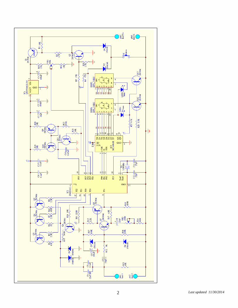
Parts List and Assembly Order
PC board 47K (R4), 4 2.2K (R5, 7. 9, 15)
2 3/8” rubber grommets
1% MF Resistors 6 10K (R1,19,20,21,23,24) Semiconductors 2 test leads, banana plugs and alligator clips
100R (R10) Miniature pushbutton switch with cap
4 1N4148 or 1N914 signal diodes (D1, D2, D5, D6)
3” tie wrap
470K (R22) 10kΩ PC-mount trim pot (VR1)
2 1N4004, 5, 6 or 7 power diodes (D3,D4)
Miscellaneous
10.0K (R6) 200Ω PC-mount trim pot (VR2)
7 2N3906 PNP transistors (Q1, Q3, Q4, Q5, Q8, Q9, Q10)
ESR chart label
1.0K (R8) 3.58MHz crystal resonator with internal capacitors
6 2N3904 NPN transistors (Q2. Q6, Q7, Q11, Q12, Q13)
contact information label
5% Resistors Capacitors LP2950CZ-5.0 3-terminal regulator low-dropout (IC1) Some are marked 78MCYFE KY5050
plastic enclosure with battery lead and hardware
220R (R11) 3 100µF 16V RB electrolytic (C1, C3, C9)
Z86E0412 programmed microcontroller (IC2)
6 #2 self tapping screws
1K (R12), 100K (R13) 22uf, 33uf or 47µF 50V bipolar RB electrolytic (C6) BP = BiPolar
4094 / MC14094 CMOS shift register (IC3)
Plastic end panel with Pre-drilled holes
220K (R14), 180R (R16) 22µF 16/25V RB electrolytic (C8)
2 LTS-5503AB 7-segment displays (DIS1, 2)
82.0 ohm resistor for alignment
6.8K (R17), 680R (R18) 470nF 63V MKT (C10) 2 3mm blue LEDs (LED1,2) 5.6 ohm for alignment
3 4.7K (R2, 27, 28) 3 100nF 50V disc or multilayer (C4,C5,C13)
Two rubber bumpons
for Display spacers 27K (R25), 2.7K (R29) 33nF 63/100WV (C7) 2 15K (R3, 26), 100R (R30) 10uf 16/25WV electrolytic
(C2)
Resistor Color Codes Value 4-Band Code (5%) 5-Band Code (1%)
5.60 Ω green blue gold gold green blue black silver brown
82 Ω grey red black gold grey red black gold brown
100 Ω brown black brown gold brown black black black brown
180 Ω brown grey brown gold brown grey black black brown
220 Ω red red brown gold red red black black brown 680 Ω blue grey brown gold blue grey black black brown
1k Ω brown black red gold brown black black brown brown
2.2k Ω red red red gold red red black brown brown
2.7k Ω red violet red gold red violet black brown brown
4.7k Ω yellow violet red gold yellow violet black brown brown
6.8k Ω blue grey red gold blue grey black brown brown
10k Ω brown black orange gold brown black black red brown
15k Ω brown green orange gold brown green black red brown
27k Ω red violet orange gold red violet black red brown
47k Ω yellow violet orange gold yellow violet black red brown
100k Ω brown black yellow gold brown black black orange brown
220k Ω red red yellow gold red red black orange brown 470k Ω yellow violet yellow gold yellow violet black orange brown
4 Last updated 11/30/2014
Construction
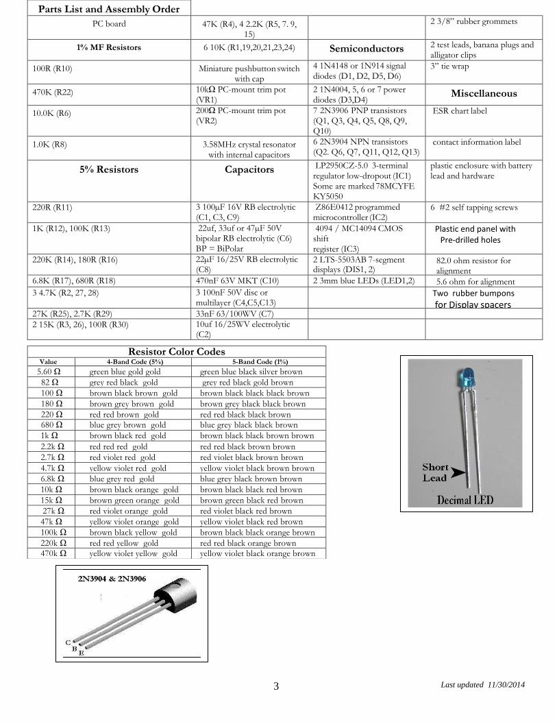
Even if the ESR Meter’s operation seems complicated, at least it is easy to build. As you can see in the photos, all the components are mounted on a single PC board which is then attached to the enclosure bottom.
Even though the pc board is high-quality with solder-mask it is still wise to check it for defects. To do this, illuminate the component side with a bright light and examine the copper side very carefully – preferably with a magnifier – for any hairline fractures in the tracks. During assembly frequently check for any solder “whiskers” or bridges and pay particular attention to any tracks, which pass between IC pads, where such defects tend to congregate and hide. It is good practice to install 5 or 6 components and then check the soldering of them under a magnifier. Then move on and install 5 or 6 more. The PC board is tightly packed and the solder pads are quite small so be very careful with your soldering. Always lift the iron vertically from a just soldered joint and never wipe it sideways as so many constructors
seem to do!
5 Last updated 11/30/2014
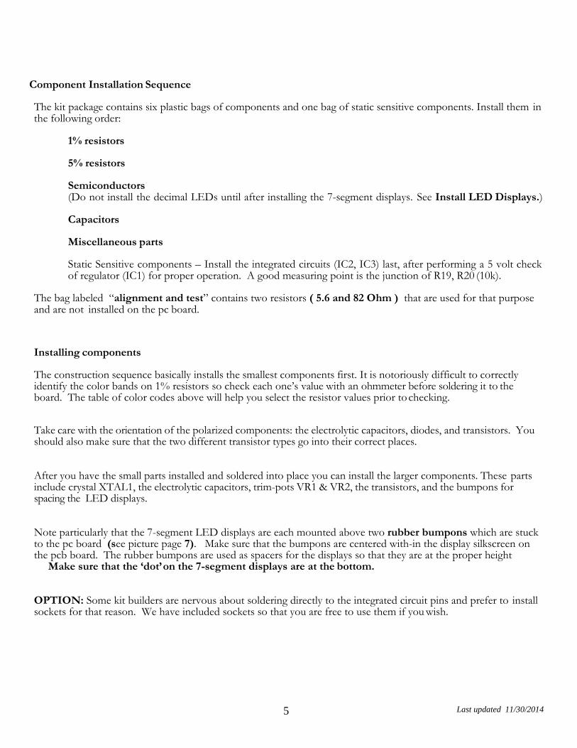
Component Installation Sequence
The kit package contains six plastic bags of components and one bag of static sensitive components. Install them in the following order:
1% resistors
5% resistors
Semiconductors (Do not install the decimal LEDs until after installing the 7-segment displays. See Install LED Displays.)
Capacitors
Miscellaneous parts
Static Sensitive components – Install the integrated circuits (IC2, IC3) last, after performing a 5 volt check of regulator (IC1) for proper operation. A good measuring point is the junction of R19, R20 (10k).
The bag labeled “alignment and test” contains two resistors ( 5.6 and 82 Ohm ) that are used for that purpose and are not installed on the pc board.
Installing components
The construction sequence basically installs the smallest components first. It is notoriously difficult to correctly identify the color bands on 1% resistors so check each one’s value with an ohmmeter before soldering it to the board. The table of color codes above will help you select the resistor values prior to checking.
Take care with the orientation of the polarized components: the electrolytic capacitors, diodes, and transistors. You should also make sure that the two different transistor types go into their correct places.
After you have the small parts installed and soldered into place you can install the larger components. These parts include crystal XTAL1, the electrolytic capacitors, trim-pots VR1 & VR2, the transistors, and the bumpons for spacing the LED displays.
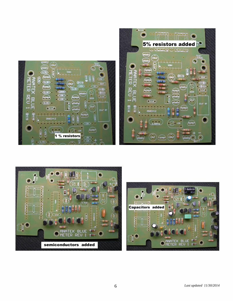
Note particularly that the 7-segment LED displays are each mounted above two rubber bumpons which are stuck to the pc board (see picture page 7). Make sure that the bumpons are centered with-in the display silkscreen on the pcb board. The rubber bumpons are used as spacers for the displays so that they are at the proper height Make sure that the ‘dot’ on the 7-segment displays are at the bottom.
OPTION: Some kit builders are nervous about soldering directly to the integrated circuit pins and prefer to install sockets for that reason. We have included sockets so that you are free to use them if you wish.
6 Last updated 11/30/2014
7 Last updated 11/30/2014
Test lead connection. Note: the tie wrap retainer.
Strip and tin the one end of the test
lead ends. Put the two grommets
into the test lead holes in the
enclosure end panel. Then feed
the test leads through the
grommets. The outside of the
panel is the finished side.
8 Last updated 11/30/2014
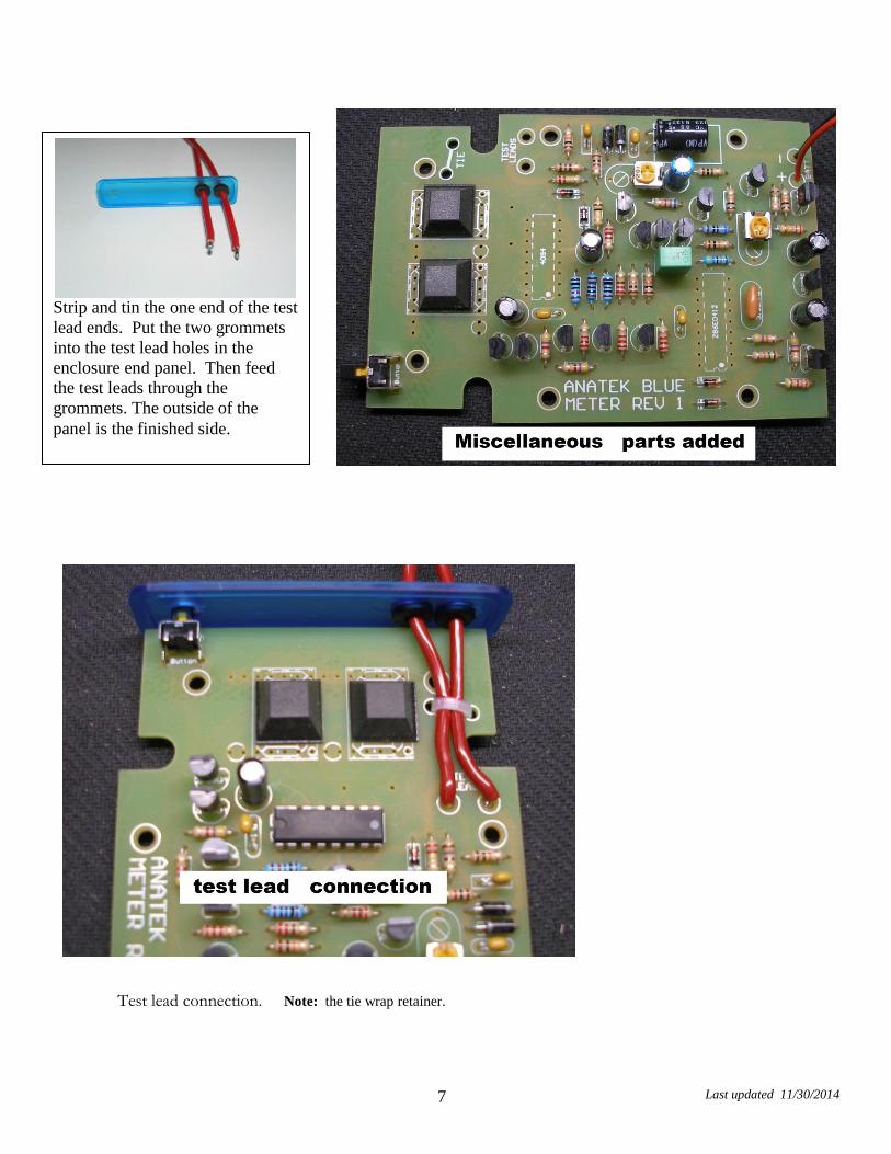
Test lead installation
Strip approximately 1/8” (2 mm) from one end of the test leads and tin using rosin core solder. Install the grommets into the enclosure end panel as shown in the picture. Then push the test leads through the grommets.
The outside of the panel is the finished side
Next, solder the test leads to the pc board and secure them with the tie wrap. Leave enough slack for the leads to clear around the pc board holes for the enclosure bosses.
Strip approximately ½ ” ( 12 mm ) from the other end of the test leads, do not tin them but bend the bare wire back on itself. Push the banana plug insulators onto the leads first and then push the bare wire end into the center hole of the banana jacks so that it is lined up with the securing screw as shown in the picture on the left.
Slide the insulator over the banana plug and screw the retaining screw in tightly.
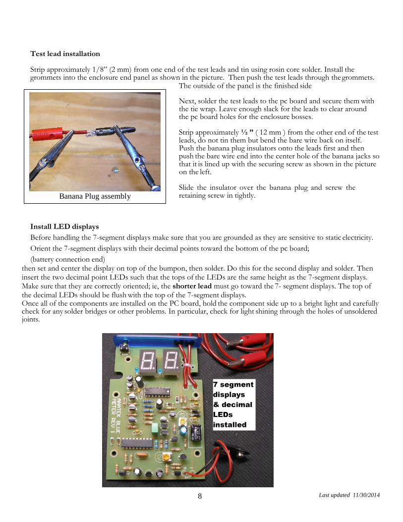
Install LED displays
Before handling the 7-segment displays make sure that you are grounded as they are sensitive to static electricity.
Orient the 7-segment displays with their decimal points toward the bottom of the pc board;
(battery connection end) then set and center the display on top of the bumpon, then solder. Do this for the second display and solder. Then insert the two decimal point LEDs such that the tops of the LEDs are the same height as the 7-segment displays. Make sure that they are correctly oriented; ie, the shorter lead must go toward the 7- segment displays. The top of the decimal LEDs should be flush with the top of the 7-segment displays. Once all of the components are installed on the PC board, hold the component side up to a bright light and carefully check for any solder bridges or other problems. In particular, check for light shining through the holes of unsoldered joints.
Banana Plug assembly
9 Last updated 11/30/2014
Battery connector
When all the components are on the board, solder the battery snap connector to the battery pads on the PC board - red to “+” and black to “-”.
Initial checks
This check requires all IC’s to be installed in their sockets. Set both VR1 and VR2 to their mid-range positions and connect a 9V supply to the battery connection. Press the pushbutton. You should see something on the 7-segment LED displays, hopefully “-” on the left hand one.
Press the pushbutton again and the meter should turn off.
Turn it back on and short the leads together. The meter should read something less than 0.5 ohm. With the leads shorted press the pushbutton again to zero the test leads. The reading should be “.00” with the left decimal lit. The reading may bounce around +.02 ohms or so due to variation in the lead contact resistance.
Calibration
It is best to calibrate the unit before assembling it into the box. That way you can correct any assembly errors that show up during calibration without having to disassemble the board from the box.
With the meter on and the leads zeroed as described above connect the supplied 82Ω 1% calibration resistor to the probes and carefully adjust VR2 until the meter reads “82.” Then check that that it reads the supplied 5.6Ω
calibration resistor reasonably accurately (5.4 to 5.8) with the middle decimal lit.
Battery warning setup
Skip this bit if you disabled the automatic switch-off function by leaving one lead of R25 disconnected (see the “Optional Modifications” section at the end of this document).
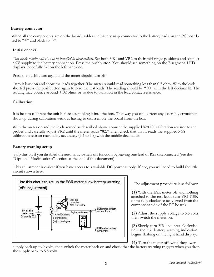
This adjustment is easiest if you have access to a variable DC power supply. If not, you will need to build the little circuit shown here.
The adjustment procedure is as follows:
(1) With the ESR meter off and nothing attached to the test leads turn VR1 (10K ohm) fully clockwise (as viewed from the component side of the PC board).
(2) Adjust the supply voltage to 5.5 volts, then switch the meter on.
(3) Slowly turn VR1 counter clockwise until the “b” battery warning indication begins flashing on the right hand display.
(4) Turn the meter off, wind the power supply back up to 9 volts, then switch the meter back on and check that the battery warning triggers when you drop the supply back to 5.5 volts.
10 Last updated 11/30/2014
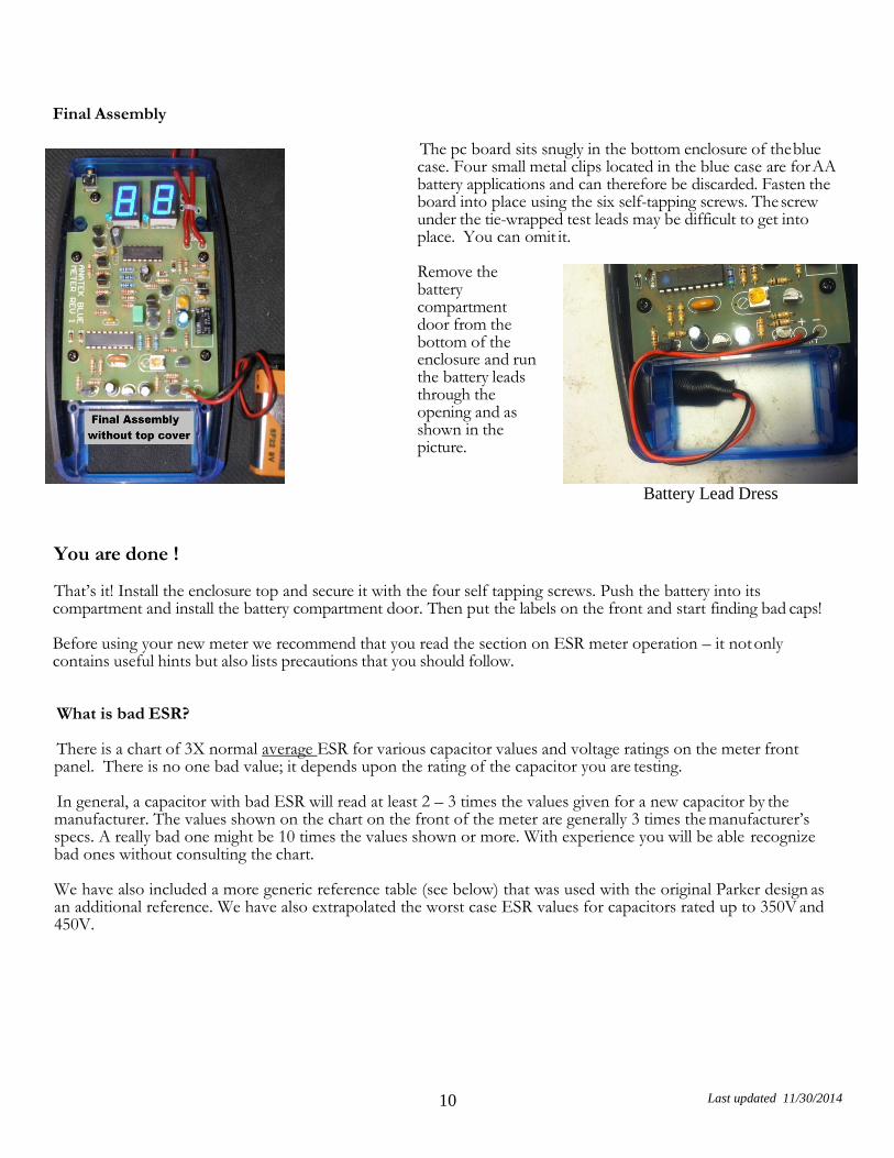
Final Assembly
The pc board sits snugly in the bottom enclosure of the blue case. Four small metal clips located in the blue case are for AA battery applications and can therefore be discarded. Fasten the board into place using the six self-tapping screws. The screw under the tie-wrapped test leads may be difficult to get into place. You can omit it.
Remove the battery compartment door from the bottom of the enclosure and run the battery leads through the opening and as shown in the picture.
Battery Lead Dress
You are done !
That’s it! Install the enclosure top and secure it with the four self tapping screws. Push the battery into its compartment and install the battery compartment door. Then put the labels on the front and start finding bad caps!
Before using your new meter we recommend that you read the section on ESR meter operation – it not only contains useful hints but also lists precautions that you should follow.
What is bad ESR?
There is a chart of 3X normal average ESR for various capacitor values and voltage ratings on the meter front panel. There is no one bad value; it depends upon the rating of the capacitor you are testing.
In general, a capacitor with bad ESR will read at least 2 – 3 times the values given for a new capacitor by the manufacturer. The values shown on the chart on the front of the meter are generally 3 times the manufacturer’s specs. A really bad one might be 10 times the values shown or more. With experience you will be able recognize bad ones without consulting the chart.
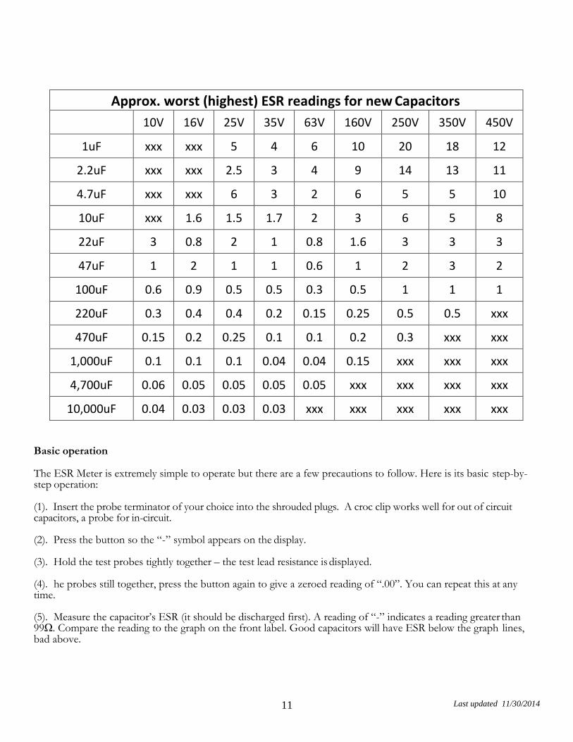
We have also included a more generic reference table (see below) that was used with the original Parker design as an additional reference. We have also extrapolated the worst case ESR values for capacitors rated up to 350V and 450V.
11 Last updated 11/30/2014
Approx. worst (highest) ESR readings for new Capacitors 10V 16V 25V 35V 63V 160V 250V 350V 450V
1uF xxx xxx 5 4 6 10 20 18 12
2.2uF xxx xxx 2.5 3 4 9 14 13 11
4.7uF xxx xxx 6 3 2 6 5 5 10
10uF xxx 1.6 1.5 1.7 2 3 6 5 8
22uF 3 0.8 2 1 0.8 1.6 3 3 3
47uF 1 2 1 1 0.6 1 2 3 2
100uF 0.6 0.9 0.5 0.5 0.3 0.5 1 1 1
220uF 0.3 0.4 0.4 0.2 0.15 0.25 0.5 0.5 xxx
470uF 0.15 0.2 0.25 0.1 0.1 0.2 0.3 xxx xxx
1,000uF 0.1 0.1 0.1 0.04 0.04 0.15 xxx xxx xxx
4,700uF 0.06 0.05 0.05 0.05 0.05 xxx xxx xxx xxx
10,000uF 0.04 0.03 0.03 0.03 xxx xxx xxx xxx xxx
Basic operation
The ESR Meter is extremely simple to operate but there are a few precautions to follow. Here is its basic step-by- step operation:
(1). Insert the probe terminator of your choice into the shrouded plugs. A croc clip works well for out of circuit capacitors, a probe for in-circuit.
(2). Press the button so the “-” symbol appears on the display.
(3). Hold the test probes tightly together – the test lead resistance is displayed.
(4). he probes still together, press the button again to give a zeroed reading of “.00”. You can repeat this at any time.
(5). Measure the capacitor’s ESR (it should be discharged first). A reading of “-” indicates a reading greater than 99Ω. Compare the reading to the graph on the front label. Good capacitors will have ESR below the graph lines, bad above.

12 Last updated 11/30/2014
(6). When you’ve finished measuring, press the button with the probes separated. The meter switches off when you release the button.
(7). When the battery is getting low, “b” flashes once per second and the display dims to conserve the remaining battery capacity.
Precautions
(1). Beware charged capacitors: The very first thing to do is to make certain that the equipment you’ll be using the ESR Meter on is disconnected from all power. Most electrolytic capacitors will be discharged by the circuitry around them within a few seconds of the power being switched off. However, be warned that filter capacitors in power supplies can remain dangerously charged, especially if there’s a fault. Before using the meter, make sure that all power supply capacitors are fully discharged. You can do this using well-insulated probes that include a series 100Ω 5W or similar power resistor. Do not just short the capacitor’s terminals together as that can not only damage the capacitor but can also be dangerous. Always allow several seconds to ensure a complete discharge. Apart from the risk of surprise and injury to you, large charged capacitors can seriously damage the meter.
(2). Watch out for interference: The meter can produce unsteady indications if its test leads pick up strong horizontal deflection signal voltages. To avoid this, be sure to keep it away from operating (CRT) TVs and monitors when making measurements.
(3). Use straight test leads: Do not add self-retracting “curly” test leads with your meter. Their inductance can cause measurement errors.
What else can it do?
Since publication of the Mk.1 design in 1996, I have received a lot of feedback from imaginative ESR Meter users regarding other uses for it. The full list is on at http://members.ozemail.com.au/~bobpar/esrhints.htm but here are some of the best ones:
(1). Resistance Measurement: as stated previously, this meter is really an AC ohmmeter with an equivalent test frequency of about 100kHz and capable of measuring non-inductive resistances from 0.01Ω to 99Ω. As such, it can be useful for locating short circuits on PC boards by showing the resistance of a copper track decreasing or increasing as you approach or move away from the short. For example, this is useful when trying to identify which one in a paralleled set of power transistors is shorted (thanks Mike Diack) or the check-out power leads and connectors (resistance is too low for a multimeter).
You can also make your own very low-value resistors by measuring out a length of nichrome or similar resistance wire to give the required resistance. In addition, the ESR Meter can be used to check the contact resistance of switches, connectors and relays. Just remember that any significant amount of inductance will cause measurement errors. You cannot measure the DC resistance of a choke, transformer winding, video head or a roll of electrical cable, for example.
(2). Basic Signal Generator: the meter’s test signal is a 500mV P-P (open circuit) burst of 8 usec pulses at a 2kHz rate, repeated several times per second. As a result, it can be used as a signal source for basic checks on amplifiers, loudspeakers and other audio components (thanks Joe Lussy). Richard Newstead reports that the meter can be used as a simple wideband signal generator with useful signals out to 30 Mhz.
Maintenance
The meter’s readings might become unsteady after a lot of use, due to oxidation or loosening of the test leads. Heavily spray the test lead plugs with contact cleaner of the kind which evaporates completely (eg, CRC “CO”
13 Last updated 11/30/2014
Contact Cleaner), then repeatedly insert and withdraw them from their sockets before it dries. If the test leads have become loose, gently re-tighten them with long needle-nose pliers. If the test probes have developed a resistive layer of oxidation, give them a wipe with a tissue soaked in tuner cleaner like CRC 2.26 or similar (thanks Joe Sopko).
It does not work, now what?
The ESR Meter’s firmware allows the microcontroller to do some basic testing of the electronics to help you narrow down a problem to one area of the board. Before doing the self-test, it’s very important to first set VR1 to the center of its adjustment range, short out R30, 100R and make sure that the meter’s supply voltage is in the range of 6.2 – 6.8V. Do not use a 9V battery for this test because it will cause a false F2 warning!
Switch the meter on by pressing and continuing to hold the button down, regardless of what the displays are showing. After five seconds, they will go blank for a moment and then show a test result for two seconds. The meter will then switch off by itself after you release the button.
If everything is more or less OK, you’ll see “.8.8” on the displays (this shows that all the display segments and decimal point LEDs are working). However, if the microcontroller has detected a problem it will flash a fault code consisting of an “F” on the left hand display and a character from 0-9 or an “A” on the right hand one.
Experience has shown that by far the most common cause of ESR meter kits not working properly is defective soldering. When a fault code directs you to a particular part of the circuit, carefully check (using a bright light and magnifier) for solder whiskers, non-soldered joints and track damage such as lifted solder pads.
If you cannot see anything abnormal, start checking for incorrect components and component placement errors such as transistors of the wrong type or with their leads in the wrong holes. If that does not show up anything, you might have received a defective component in the kit, though this is very rare. OK, here is a list of what the fault codes indicate:
F0: Q11 is not discharging C10. Check around Q11 (2N3904), R21 (10kΩ), R22 (470kΩ) and pin 4 of IC2 (Z86E0412).
F1: C10 is charging too quickly. Check that R22 really is 470kΩ and that R19 & R20 are 10kΩ. Make sure C10 is 470nF (0.47µF, code “474”). Check also for soldering and component placement problems around transistors Q9 & Q10 (2N3906).
F2: C10 is charging too slowly (or not at all). Check around Q9, Q10 (2N3906), R22 (470kΩ), R19 & R20 (10kΩ) and C10 (470nF).
F3: Pulse amplifier output bias <440mV (i.e., at collector of Q8). Check R13 (100kΩ) & R14 (220kΩ) for correct values and check that D6 isn’t reversed. Check around Q7 (2N3904), Q8 (2N3906) and around pin 8 of IC2 plus associated components.
F4: Pulse amplifier output bias >1V. Carry out the same checks as for “F3” code. Check also that D5 isn’t reversed.
F5: A test current source is permanently on. Check area around Q3, Q4 & Q5 (all 2N3906); R5, R7 & R9 (2.2kΩ); and pins 15, 16 & 17 of IC2.
F6: No output from pulse amplifier. Check around C7 (33nF), R12 (1kΩ), D3 & D4 (1N4002), C5 (100nF) and C6 (47µF bipolar).
F7: Q3 not sourcing current. Check around Q3 (2N3906), R5* (2.2kΩ), R6 (10kΩ) and pin 15 of IC2.
14 Last updated 11/30/2014
F8: Q4 not sourcing current. Check around Q4 (2N3906), R7* (2.2kΩ), R8 (1kΩ) and pin 16 of IC2. F9: Q5 not sourcing current. Check around Q5 (2N3906), R9* (2.2kΩ), R10 (100Ω), IC2 pin 17.
F9: Q5 not sourcing current. Check around Q5 (2N3906), R9* (2.2kΩ), R10 (100Ω), IC2 pin 17. FA: Q6 not switching on. Check around Q6 (2N3904), R24 (10kΩ) and pin 1 of IC2. The microcontroller cannot perform detailed tests on every component, so it’s possible that your meter is malfunctioning even though the self- testing hasn’t shown up a problem. For example, if the meter is behaving strangely, “freezing” up or giving absurd readings on some values of test resistors, the most likely cause is a mix-up in the values of R6 (10kΩ), R8 (1kΩ) and R10 (100Ω). On the other hand, if the meter produces readings but there’s something wrong with the displayed characters, this is almost certainly due to one or more solder bridges between the pins of the displays or around IC3.
If the meter does not stay switched on when you push the button, check around Q2 (2N3904), R3 (15kΩ), R29 (2.7kΩ) and pin 2 of IC2. If it switches off when you short the test leads, R2 (4.7kΩ) may be the incorrect value or Q1 (2N3906) may have a low current gain. Finally, if you can’t get the meter into the test mode, zero it or switch it off, check for solder “whiskers” and open circuits around pin 3 of IC2, R4 (47kΩ) and D2.
If none of the above has helped you to identify the problem, there is a page of fault-finding information on http://members.ozemail.com.au/~bobpar/esrprob.htm. Do a Google search for “ESR meter faultfinding” if you can’t find it. There is also the AnaTek customer forum at www.anatekcorp.com/forum with lots of hints, tips and ideas on how to use your meter.
Disabling automatic switch-off
If you’d like to power the meter from an external 9V DC supply and have it operating continuously, just disconnect one end of R25 (47kΩ). This disables the automatic switch-off function but note that the low battery warning will no longer work if you do this.
Of course, you can easily reconnect R25 if you change your mind in the future.
For more modifications, including a buzzer to help you discriminate between good and bad electrolytics without having to look at the meter, go to the ESR Meter Hints web page at : http://members.ozemail.com.au/~bobpar/esrhints.htm If all else fails send a question to [email protected].