Embed Size (px)
Citation preview

Application Note
AN_391
EVE Platform Guide
Version 1.1
Issue Date: 2016-11-08
This application note is intended as a companion to the examples for the FT8xx series of devices.
Each example for the EVE family has a source code zip file supporting a variety of platforms and
an accompanying application note which describes the operation of the sample code. This
application note provides additional information on the platforms used to run the sample code and
on which platforms and EVE devices are compatible with each of the samples.

2 Product Page
Document Feedback Copyright © Bridgetek Limited
Application Note
AN_391 EVE Platform Guide Version 1.1
Document No.: BRT_000055 Clearance No.: BRT#046
Table of Contents
1 Introduction .............................................................. 4
1.1 Overview ............................................................................. 4
1.2 Scope .................................................................................. 4
2 Sample Application Matrix ......................................... 5
3 Loading the Demonstration Code ............................... 6
3.1 Visual Studio (MSVC MPSSE) ............................................... 6
3.1.1 Hardware Requirement ........................................................................ 6
3.1.2 Software Requirement ......................................................................... 6
3.1.3 Folder Structure.................................................................................. 7
3.1.4 Loading the Project ............................................................................. 7
3.1.5 Configuring the Project ........................................................................ 7
3.1.6 Running the Project ............................................................................. 7
3.1.7 Stopping the Demonstration ................................................................. 8
3.2 Arduino ............................................................................... 8
3.2.1 Hardware Requirement ........................................................................ 8
3.2.2 Software Requirement ......................................................................... 8
3.2.3 Folder Structure.................................................................................. 8
3.2.4 Loading the Code ................................................................................ 9
3.2.5 Configuring the Project ........................................................................ 9
3.2.6 Loading the Code ................................................................................ 9
3.3 MSVC Emulator .................................................................. 10
3.3.1 Hardware Requirement ...................................................................... 10
3.3.2 Software Requirement ....................................................................... 10
3.3.3 Folder Structure................................................................................ 10
3.3.4 Loading the Project ........................................................................... 10
3.3.5 Configuring the Project ...................................................................... 10
3.3.6 Running the Project ........................................................................... 10
3.4 FT90x Platform .................................................................. 11
3.4.1 Hardware Requirement ...................................................................... 11

3 Product Page
Document Feedback Copyright © Bridgetek Limited
Application Note
AN_391 EVE Platform Guide Version 1.1
Document No.: BRT_000055 Clearance No.: BRT#046
3.4.2 Software Requirement ....................................................................... 12
3.4.3 Folder Structure................................................................................ 12
3.4.4 Dependencies ................................................................................... 12
3.4.5 Loading the Project ........................................................................... 13
3.4.6 Configuring the Project ...................................................................... 13
3.4.7 Project Build ..................................................................................... 13
3.4.8 Project Download .............................................................................. 13
4 Platform Configuration ............................................ 15
5 Contact Information ................................................ 24
Appendix A– References .............................................. 25
Document References ............................................................... 25
Acronyms and Abbreviations ..................................................... 25
Appendix B – List of Tables & Figures .......................... 26
List of Figures ........................................................................... 26
List of Tables ............................................................................. 26
Appendix C– Revision History ...................................... 27

4 Product Page
Document Feedback Copyright © Bridgetek Limited
Application Note
AN_391 EVE Platform Guide Version 1.1
Document No.: BRT_000055 Clearance No.: BRT#046
1 Introduction
This application note is intended as a companion to the examples for the FT8xx series of devices.
Each example for the EVE family has a source code zip file supporting a variety of platforms:
Microsoft Visual Studio
FT900
MSVC Emulator
Arduino
Each example also has an accompanying application note which describes the operation of the
sample code.
This document provides additional information on the platforms used to run the sample code and
on which platforms and EVE devices are compatible with each of the samples.
1.1 Overview
This guide covers the following topics:
Matrix showing compatibility of each sample with the different EVE devices and platforms
Example of how to load and run the demo on each platform
Highlighting the sections of platform.h which can be used to select the correct code options
for the target platform
1.2 Scope
This document is intended to be used in conjunction with the source code project and the
application note specific to the sample program. It uses the Gradient example for illustration but
does not cover the specific graphics aspects demonstrated in each example.

5 Product Page
Document Feedback Copyright © Bridgetek Limited
Application Note
AN_391 EVE Platform Guide Version 1.1
Document No.: BRT_000055 Clearance No.: BRT#046
2 Sample Application Matrix
This section shows the compatibility of the demo projects across the different EVE devices and
demonstration boards. The EVE2 column indicates the demos which currently support the EVE2
(FT81x) devices in addition to the FT80x.
Figure 2.1 Platform table for EVE demos
Notes: Where EVE2 compatibility is indicated for a sample, this may apply only to certain EVE2 devices and
platforms as detailed in the table.
The FT81x uses a different register map from the FT80x in order to support the additional registers
required for its extended functionality. The EVE2 compatible demos include updated header files with
defines to allow either register map to be defined. These demos also have some code specific to the
FT80x or FT81x which is enabled depending on the #defines selected in the platform header file.
Application Name EVE2
VM
80
0B
43
/VM
80
0B
50
VM
80
0B
35
VM
80
1B
43
/VM
80
1B
50
VM
81
0C
50
VM
80
0P
43
/VM
80
0P
50
VM
80
0P
35
VM
80
1P
43
/VM
80
1P
50
VM
80
0B
43
/VM
80
0B
50
VM
80
0B
35
VM
80
1B
43
/VM
80
1B
50
VM
80
0B
43
/VM
80
0B
50
VM
80
0B
35
VM
80
1B
43
/VM
80
1B
50
VM
81
0C
50
ME8
10
A-H
V3
5R
ME8
12
A-W
H5
0R
ME8
13
A-W
H5
0C
SampleApp
FT_App_Lift
FT_App_Gauge
FT_App_Gradient
FT_App_Sketch
FT_App_Signature
FT_App_Signals
FT_App_MeterDemo
FT_App_Metaballs
FT_App_Mainmenu
FT_App_Keyboard
FT_App_Jackpot
FT_App_Imageviewer
FT_App_Graph
FT_App_RotaryDial
FT_App_Logo
FT_App_PlayVideo
FT_App_WashingMachine
FT_App_Refrigerator
FT_App_Clocks
FT_App_FtClocks
FT_App_Polygon
FT_App_CustomWidgets
FT_App_Player
FT_App_Restaurant
FT_App_Music
FT_App_Reader
FT_App_ChineseFont
Platforms
FT90XMSVC MPSSE Arduino MSVC Emulator

6 Product Page
Document Feedback Copyright © Bridgetek Limited
Application Note
AN_391 EVE Platform Guide Version 1.1
Document No.: BRT_000055 Clearance No.: BRT#046
3 Loading the Demonstration Code
This section provides details of loading and running the code on the FT90x, Visual Studio, Arduino
and MSVC Emulator platforms.
The source code zip file for each project can be downloaded from the page below:
http://www.ftdichip.com/Support/SoftwareExamples/FT800_Projects.htm
The Gradient example is used in the screenshots for illustration purposes only. However, similar
steps apply for the other demonstrations.
Note: For some demos, when running on the Arduino and FT900 platforms, a FAT formatted SD card is
required and all files in the “Test” folder must be copied to the root directory of the SD card. The Test folder
will be empty if the SD card is not required by the demo.
3.1 Visual Studio (MSVC MPSSE)
This section covers the loading of the demonstration code on a PC with Visual Studio installed. In
this case, the code running on the Visual Studio application represents the SPI Master which
controls the FT8xx device.
3.1.1 Hardware Requirement
This section applies to hardware configurations using the CM232H cable, VA800A-SPI or the
VM8xxBU which have an on-board USB-SPI interface. The code requires an interface based on the
FT232H chipset and does not support 3rd party USB->SPI adapters.
If using the C232HM, the pin-out below should be used when connecting the wires to the header of
the FT8xx development module (e.g. VM800B/VM800C).
Table 1 C232HM Connections to the VM8xx pins
3.1.2 Software Requirement
The demo applications were developed on MSVC 2010 Express edition. The project can also be
opened on later versions of MSVC which will migrate from the older version. Note that in some
cases MSVC will not modify the platform tool set during the migration of the project.
Before running the code, ensure that the USB-SPI cable/interface (e.g. C232HM) is connected to
the USB port of the computer and the FTDI Windows drivers are loaded. The adapter should
appear under the Universal Serial Bus Controllers section of the Device Manager.
If the driver installation has not been carried out, please consult the user guide for the USB->SPI
interface for instructions on installing the interface.
SCK ORANGE
MOSI YELLOW
MISO GREEN
CS# BROWN
PD# BLUE
GND BLACK

7 Product Page
Document Feedback Copyright © Bridgetek Limited
Application Note
AN_391 EVE Platform Guide Version 1.1
Document No.: BRT_000055 Clearance No.: BRT#046
3.1.3 Folder Structure
The provided zip file supports various platforms. The main files related to the MSVC platform are:
Folder Project -> Msvc_win32 contains the project and solution files (e.g. Project ->
Msvc_win32 -> FT_App_Gradient -> Ft_App_Gradient.sln)
Folder Src contains the c source files for the main application and supporting functions
Folder Hdr contains header files and sub-folder Msvc_win32 contains further headers for
the MSVC platform
The Test folder contains supporting files for the project where required (for example,
bitmap images)
Full details are given in the readme file included in the project zip package.
3.1.4 Loading the Project
The code project can then be opened within the Visual Studio software. The solution can be
opened by double-clicking the .sln file (e.g. Project -> Msvc_win32 -> FT_App_Gradient ->
Ft_App_Gradient.sln) or by File -> Open Project/Solution within the Visual Studio software itself.
3.1.5 Configuring the Project
Before running the demo, ensure that the project is configured for the correct FT8xx board and
screen size within the FT_Platform.h file which can be opened from the Solution Explorer window
in Visual Studio. Please refer to section 4 for details.
3.1.6 Running the Project
To run the project, perform a clean or re-build all via the BUILD menu. Then, select the Debug
mode from the drop-down and start debugging.
Figure 3.1 Visual Studio screenshot
The command window will appear a few seconds after clicking the Local Windows Debugger button
and the initial calibration screen will be displayed on the module’s LCD screen.

8 Product Page
Document Feedback Copyright © Bridgetek Limited
Application Note
AN_391 EVE Platform Guide Version 1.1
Document No.: BRT_000055 Clearance No.: BRT#046
Figure 3.2 Command window with demo running
3.1.7 Stopping the Demonstration
To stop debugging, the Visual Studio menu item DEBUG -> Stop Debugging can be used or the
command window can be closed via the cross button at the top-right of the command window.
Breakpoints and stepping can be used when running the code to allow the operation to be more
easily understood. Note that the code builds up buffers of commands for the FT8xx and so the
result will not be visible until the Swap and Flush_Co_Buffer functions have been executed.
3.2 Arduino
The demo can be loaded into the Arduino IDE in order to be run on an Arduino platform.
3.2.1 Hardware Requirement
The provided sample can be run on the VM800P and VM801P boards which have an Arduino-
compatible ATMEGA328 MCU. These boards have a USB-UART interface to allow programming via
the bootloader in the MCU.
They can also be run on the Arduino Pro platform along with a VM800B/C or VM801B. For details
of the connections, refer to AN_246 (Sample App Arduino introduction).
An SD card is required for some examples where a large amount of image data is required.
3.2.2 Software Requirement
This requires the Arduino IDE to be installed. The samples require Arduino 1.0.1 or later. The IDE
can be obtained from the Arduino homepage: https://www.arduino.cc/
Note: For the Arduino platform of some demos, a FAT formatted SD card is required and in this case all files in
the “Test” folder must be copied to the root directory of the SD card. The Test folder may be empty in the
sample code package and in this case no SD card is needed.
3.2.3 Folder Structure
The provided zip file supports various platforms. The main files related to the Arduino platform
are:

9 Product Page
Document Feedback Copyright © Bridgetek Limited
Application Note
AN_391 EVE Platform Guide Version 1.1
Document No.: BRT_000055 Clearance No.: BRT#046
Folder Project -> Arduino contains the .ino sketch file, along with Arduino versions of the
library functions and headers. (e.g. Project -> Arduino -> FT_App_Gradient ->
Ft_App_Gradient.ino)
The Test folder contains supporting files for the project where required (for example,
bitmap images)
Full details are given in the readme file included in the project zip package.
3.2.4 Loading the Code
After opening the .ino file in the Arduino IDE, the tabs should show the code and header files as
displayed below.
Figure 3.3 Arduino IDE with code project open
3.2.5 Configuring the Project
Before running the demo, ensure that the project is configured for the correct FT8xx board and
screen size within the FT_Platform.h file which can be opened from the Solution Explorer window
in Visual Studio. Please refer to section 4 for further details.
3.2.6 Loading the Code
The VM800P/VM801P should be connected to the PC and the drivers installed. The Windows device
manager (under the Ports section) can be used to verify which COM port has been assigned.
In the Arduino IDE, select the COM port under Tools _ Serial Port. Ensure that the Tools -> Board
setting is “Arduino Pro or Pro Mini (5V, 16MHz) w/ATMega328”
Click the Verify button (which has a tick shaped icon) to compile the code. The adjacent upload
button (with an arrow-shaped icon) can be used to compile and upload the code to the MCU. The
LEDs on the VM800P/801P indicate the data traffic during upload and shortly after these stop
blinking, the board will re-start and the application will run.

10 Product Page
Document Feedback Copyright © Bridgetek Limited
Application Note
AN_391 EVE Platform Guide Version 1.1
Document No.: BRT_000055 Clearance No.: BRT#046
3.3 MSVC Emulator
The MSVC Emulator version of the project allows the sample to be run without any hardware. It
uses the EVE Screen Editor utility provided by FTDI
3.3.1 Hardware Requirement
Running on the MSVC Emulator does not require any hardware as the screen is simulated on the
PC application.
However, by connecting an EVE module to the PC via the FTDI MPSSE interface, it may be used to
preview the result on the actual display. For example
VM800B/C, VM801B/C, VM810C can be used in conjunction with a USB-SPI adapter (CM232H or VA800A-SPI)
VM80xBU has the USB-SPI adapter on-board and can be connected directly to the PC’s USB port.
When using the C232HM, the connections are the same as in section 3.1.
3.3.2 Software Requirement
The example project requires Visual Studio 2012 (or Express 2012) or later to be installed.
The latest FTDI EVE Screen Editor must also be installed. This can be obtained from
http://www.ftdichip.com/Support/Utilities.htm#EVEScreenEditor
3.3.3 Folder Structure
The provided zip file supports various platforms. The main files related to the Emulator platform
are:
Folder Project -> MSVC_Emulator contains the project and solution files (e.g. Project ->
MSVC_Emulator -> FT_App_Gradient -> Ft_App_Gradient.sln)
Folder Src contains the c source files for the main application and supporting functions
Folder Hdr contains header files and sub-folder MSVC_Emulator contains further headers
for the MSVC platform
The Test folder contains supporting files for the project where required (for example,
bitmap images)
Full details are given in the readme file included in the project zip package.
3.3.4 Loading the Project
The code project can then be opened within the Visual Studio software. The solution can be
opened by double-clicking the .sln file (e.g. Project -> MSVC_Emulator -> FT_App_Gradient ->
Ft_App_Gradient.sln) or by File -> Open Project/Solution within the Visual Studio software itself.
3.3.5 Configuring the Project
Before running the demo, ensure that the project is configured for the correct FT8xx board and
screen size within the FT_Platform.h file which can be opened from the Solution Explorer window
in Visual Studio. Please refer to section 4.
3.3.6 Running the Project
To run the project, select the Release mode from the drop-down and click the Local Windows
Debugger button.

11 Product Page
Document Feedback Copyright © Bridgetek Limited
Application Note
AN_391 EVE Platform Guide Version 1.1
Document No.: BRT_000055 Clearance No.: BRT#046
Figure 3.4 Code project open in Visual Studio
A window will appear on the PC which represents the screen. Clicking with the mouse simulates
touches on the screen. Note that the Screen Editor program itself will not open or be visible but
must be installed in order for the emulation to work.
Figure 3.5 Window simulating the FT8xx screen
3.4 FT90x Platform
This section covers the loading of the example on an FT90x platform.
3.4.1 Hardware Requirement
EVE Module card (e.g. ME810A-HV35R, ME812A-WH50R, ME813A-WH50C)
UMFTPD2A Module for program/debug
FT900 board (e.g. MM900EVx)
Micro USB cables
The MM900EVx module is mated onto the top of the ME8xx Board as shown in Figure 3.6. A USB micro cable is used to power both boards via the connector on the MM900EVx.

12 Product Page
Document Feedback Copyright © Bridgetek Limited
Application Note
AN_391 EVE Platform Guide Version 1.1
Document No.: BRT_000055 Clearance No.: BRT#046
The UMFTPD2A Module is used to download the program to the FT900 Board via the MicroMatch ribbon cable connector. It connects to the PC via a second micro USB cable which provides power and communications to the UMFTPD2A from the host PC. Further details can be found in the
datasheet.
Figure 3.6 Hardware connections
Note: The yellow and orange jumper wires are for UART communication between FT900 and the PC via a spare UART channel on the UMFTPD2A and are not required for programming the FT900 or running the code samples. Only the grey ribbon cable is required.
3.4.2 Software Requirement
FT900 Toolchain. See AN_325 FT900 Toolchain Installation Guide.
Software package for this Application Note (see section 3)
3.4.3 Folder Structure
The provided zip file supports various platforms. The main files related to the FT900 platform are:
Folder "Project\FT90x" contains the project file.
The source files are included in Src folder.
The header files are included in Hdr and Hdr\FT90x folder.
The library files such as fatfs are included in bin\FT90x\ (see note below)
The Test folder contains any supporting files which should be placed on the SD card (for example, bitmaps). (see note below)
Full details are given in the readme file included in the project zip package.
Note: For the Arduino and FT900 versions of some samples, a FAT formatted SD card is required. All files in
the “Test” folder must be copied to the root directory of the SD card. The libfatfs.a library should also be
included in the project when the program is running on FT900 platform. The Test and bin\FT90x folders may be
empty in cases where the sample code does not require images etc. to be stored on an SD card.
3.4.4 Dependencies
The Application uses the SPI, UART, etc. libraries provided by FTDI as part of the FT900 Toolchain.
The following header files should also be included in the code: ff.h, ffconf.h, diskio.h and integer.h.
For further details of FT900 toolchain usage, see AN_325 (FT900 Toolchain Installation Guide) and
AN_381 Sample Application for an example on how to import a project into the FT900 IDE.
13 Product Page
Document Feedback Copyright © Bridgetek Limited
Application Note
AN_391 EVE Platform Guide Version 1.1
Document No.: BRT_000055 Clearance No.: BRT#046
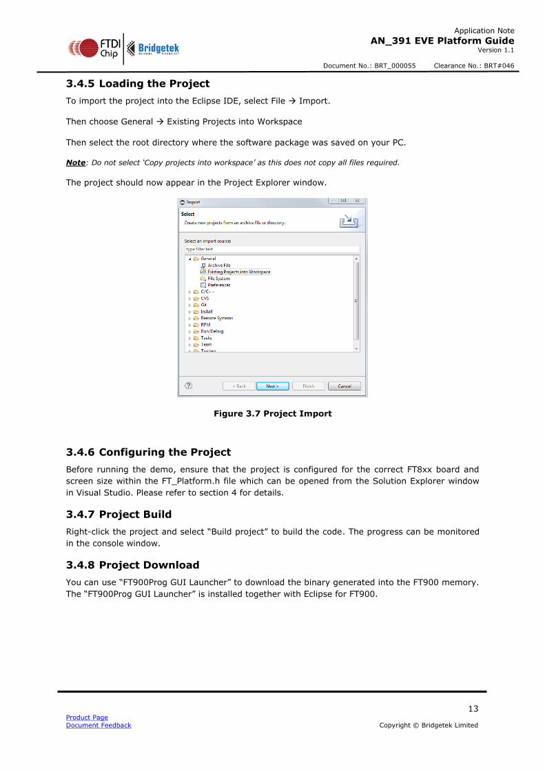
3.4.5 Loading the Project
To import the project into the Eclipse IDE, select File Import.
Then choose General Existing Projects into Workspace
Then select the root directory where the software package was saved on your PC.
Note: Do not select ‘Copy projects into workspace’ as this does not copy all files required.
The project should now appear in the Project Explorer window.
Figure 3.7 Project Import
3.4.6 Configuring the Project
Before running the demo, ensure that the project is configured for the correct FT8xx board and
screen size within the FT_Platform.h file which can be opened from the Solution Explorer window
in Visual Studio. Please refer to section 4 for details.
3.4.7 Project Build
Right-click the project and select “Build project” to build the code. The progress can be monitored
in the console window.
3.4.8 Project Download
You can use “FT900Prog GUI Launcher” to download the binary generated into the FT900 memory.
The “FT900Prog GUI Launcher” is installed together with Eclipse for FT900.

14 Product Page
Document Feedback Copyright © Bridgetek Limited
Application Note
AN_391 EVE Platform Guide Version 1.1
Document No.: BRT_000055 Clearance No.: BRT#046
Figure 3.8 FT900Prog GUI Launcher
For other download and debug options, see AN_325 FT900 Toolchain Installation Guide.

15 Product Page
Document Feedback Copyright © Bridgetek Limited
Application Note
AN_391 EVE Platform Guide Version 1.1
Document No.: BRT_000055 Clearance No.: BRT#046
4 Platform Configuration
The Visual Studio, FT900 and Emulator platforms use a common source file for the main
application (e.g. Gradient.c) which in turn calls the library functions and commands from the
library files in the project.
The code includes #defines in order to support these different host platforms and also to allow the
same source code to support the different screen sizes and EVE family members. For example, to
select the correct header files for FT80x/FT81x, when using FT81x specific features or to allow for
capacitive or resistive screen types.
After loading the demonstration code and before running it, please ensure that the settings match
the hardware platform.
The sections below highlight the main settings for each platform type.
Visual Studio
A section of the platform.h file is shown below.
The first area highlighted allows configuration of the FT8xx module being used. One define
should be un-commented to correspond to the board in use. The file uses further #if
defined areas to configure the other settings based on the module.
The second area highlighted can be used in cases where it is required to control the
#defines individually to obtain a custom combination. In this case, the defines from the
first highlighted section would be commented.
Note that after changing any settings, it is necessary to re-build the project in Visual Studio so
that the code is re-built with the new settings and options. #ifndef _FT_PLATFORM_H_ #define _FT_PLATFORM_H_ /* platform specific macros */ #define MSVC_PLATFORM (1) // enable by default for MSVC platform /* module specific macros */ #define VA800A_SPI (1) #define VM800B43_50 (1) Select one of these to match the EVE board being used //#define VM800B35 (1) //#define VM801B43_50 (1) //#define VM810C50 (1) #ifdef VM800B43_50 /* Define all the macros specific to VM800B43_50 module */ #define FT_800_ENABLE (1) #define DISPLAY_RESOLUTION_WQVGA (1) #define RESISTANCE_THRESHOLD (1200) #endif /* VM800B43_50 */ #ifdef VM800B35 #define FT_800_ENABLE (1) #define DISPLAY_RESOLUTION_QVGA (1) #define RESISTANCE_THRESHOLD (1200) #endif /* VM800B35 */ #ifdef VM801B43_50 #define FT_801_ENABLE (1) #define DISPLAY_RESOLUTION_WQVGA (1) #endif #ifdef VM810C50 /* Define all the macros specific to VM800B43_50 module */

16 Product Page
Document Feedback Copyright © Bridgetek Limited
Application Note
AN_391 EVE Platform Guide Version 1.1
Document No.: BRT_000055 Clearance No.: BRT#046
#define FT_810_ENABLE (1) #define DISPLAY_RESOLUTION_WVGA (1) #define RESISTANCE_THRESHOLD (1200) #endif /* VM810C50 */ /* Module connected from PC to basic modules */ #ifdef VA800A_SPI #define ENABLE_SPI_SINGLE (1) #endif /* VA800A_SPI */ /* Custom configuration */ #if (!defined(VM800B43_50) && !defined(VM800B35) && !defined(VM801B43_50) && !defined(VM810C50)) /* Display configuration specific macros */ This section allows the defines to be controlled individually #define DISPLAY_RESOLUTION_QVGA (1) if no selections were made for the EVE module type #define DISPLAY_RESOLUTION_WQVGA (1) #define DISPLAY_RESOLUTION_WVGA (1) #define DISPLAY_RESOLUTION_HVGA_PORTRAIT (1) /* Chip configuration specific macros */ #define FT_800_ENABLE (1) #define FT_801_ENABLE (1) #define FT_810_ENABLE (1) #define FT_811_ENABLE (1) #define FT_812_ENABLE (1) #define FT_813_ENABLE (1) /* SPI specific macros - compile time switches for SPI single, dial and quad use cases */ #define ENABLE_SPI_SINGLE (1) #define ENABLE_SPI_DUAL (1) #define ENABLE_SPI_QUAD (1) /* Display driver configurations - mainly for ME900EV1 modules */ #define ENABLE_ILI9488_HVGA_PORTRAIT (1) #endif #if defined(FT_800_ENABLE) || defined(FT_801_ENABLE) #define FT_80X_ENABLE (1) #endif #if (defined(FT_810_ENABLE) || defined(FT_811_ENABLE) || defined(FT_812_ENABLE) || defined(FT_813_ENABLE)) #define FT_81X_ENABLE (1) #endif /* C library inclusions */ #include <stdlib.h> #include <stdio.h> #include <string.h> #include <math.h> #include <Windows.h> #include <direct.h> #include <time.h> #include <io.h> /* D2xx and SPI from FTDI inclusions */ #include "ftd2xx.h" #include "LibMPSSE_spi.h" /* HAL inclusions */ #include "FT_DataTypes.h" #include "FT_Gpu_Hal.h" #include "FT_Gpu.h" #include "FT_CoPro_Cmds.h" #include "FT_Hal_Utils.h" /* Macros specific to optimization */ #define BUFFER_OPTIMIZATION (1) #define BUFFER_OPTIMIZATION_DLRAM (1) #define BUFFER_OPTIMIZATION_CMDRAM (1) #define MSVC_PLATFORM_SPI (1) #define FT800_SEL_PIN 0 #define FT800_PD_N 7 #endif /*_FT_PLATFORM_H_*/
/* Nothing beyond this*/

17 Product Page
Document Feedback Copyright © Bridgetek Limited
Application Note
AN_391 EVE Platform Guide Version 1.1
Document No.: BRT_000055 Clearance No.: BRT#046
Arduino
A section of the platform.h file is shown below.
The first area highlighted allows configuration of the FT8xx module being used. One define
should be un-commented to correspond to the board in use. The file uses further #if
defined areas to configure the other settings based on the module.
The second area highlighted can be used in cases where it is required to control the
#defines individually to obtain a custom combination. In this case, the defines from the
first highlighted section would be commented.
Note that after changing any settings, it is necessary to re-build the project via the Verify (tick)
button. #ifndef _FT_PLATFORM_H_ #define _FT_PLATFORM_H_ #define ARDUINO_PLATFORM /* Module specific configurations */ Select one of these to match the EVE board being used #define VM800P43_50 //#define VM800P35 //#define VM801P43_50 //#define VM800B43_50 //#define VM800B35 //#define VM801B43_50 #ifdef VM800P43_50 #define DISPLAY_RESOLUTION_WQVGA (1) #define FT_800_ENABLE (1) #define ENABLE_SPI_SINGLE (1) #define FT_ARDUINO_ATMEGA328P_I2C (1) #define RTC_PRESENT (1) #define FT800_CS (9) #define FT_SDCARD_CS (8) #define FT800_INT (3) #define FT800_PD_N (4) #define FT_ARDUINO_PRO_SPI_CS FT800_CS #define ARDUINO_PLATFORM_SPI #define ARDUINO_PLATFORM_COCMD_BURST #define RESISTANCE_THRESHOLD (1200) #endif #ifdef VM800P35 #define DISPLAY_RESOLUTION_QVGA (1) #define FT_800_ENABLE (1) #define ENABLE_SPI_SINGLE (1) #define FT_ARDUINO_ATMEGA328P_I2C (1) #define RTC_PRESENT (1) #define FT800_CS (9) #define FT_SDCARD_CS (8) #define FT800_INT (3) #define FT800_PD_N (4) #define FT_ARDUINO_PRO_SPI_CS FT800_CS #define ARDUINO_PLATFORM_SPI #define ARDUINO_PLATFORM_COCMD_BURST #define RESISTANCE_THRESHOLD (1200) #endif #ifdef VM801P43_50 #define DISPLAY_RESOLUTION_WQVGA (1) #define FT_801_ENABLE (1) #define ENABLE_SPI_SINGLE (1) #define FT_ARDUINO_ATMEGA328P_I2C (1) #define RTC_PRESENT (1) #define FT800_CS (9) #define FT_SDCARD_CS (8) #define FT800_INT (3) #define FT800_PD_N (4) #define FT_ARDUINO_PRO_SPI_CS FT800_CS #define ARDUINO_PLATFORM_SPI

18 Product Page
Document Feedback Copyright © Bridgetek Limited
Application Note
AN_391 EVE Platform Guide Version 1.1
Document No.: BRT_000055 Clearance No.: BRT#046
#define ARDUINO_PLATFORM_COCMD_BURST #endif #ifdef VM800B43_50 #define DISPLAY_RESOLUTION_WQVGA (1) #define FT_800_ENABLE (1) #define ENABLE_SPI_SINGLE (1) #define FT800_INT (3) #define FT800_PD_N (4) #define FT_SDCARD_CS (5) #define FT800_CS (10) #define FT_ARDUINO_PRO_SPI_CS (10) #define ARDUINO_PLATFORM_SPI #define ARDUINO_PLATFORM_COCMD_BURST #define RESISTANCE_THRESHOLD (1200) #endif #ifdef VM800B35 #define DISPLAY_RESOLUTION_QVGA (1) #define FT_800_ENABLE (1) #define ENABLE_SPI_SINGLE (1) #define FT800_INT (3) #define FT800_PD_N (4) #define FT_SDCARD_CS (5) #define FT800_CS (10) #define FT_ARDUINO_PRO_SPI_CS (10) #define ARDUINO_PLATFORM_SPI #define ARDUINO_PLATFORM_COCMD_BURST #define RESISTANCE_THRESHOLD (1200) #endif #ifdef VM801B43_50 #define DISPLAY_RESOLUTION_WQVGA (1) #define FT_801_ENABLE (1) #define ENABLE_SPI_SINGLE (1) #define FT800_INT (3) #define FT800_PD_N (4) #define FT_SDCARD_CS (5) #define FT800_CS (10) #define FT_ARDUINO_PRO_SPI_CS (10) #define ARDUINO_PLATFORM_SPI #define ARDUINO_PLATFORM_COCMD_BURST #endif /* Custom configuration set by the user */ #if (!defined(VM800P43_50) && !defined(VM800P35) &&!defined(VM801P43_50) &&!defined(VM800B43_50) &&!defined(VM800B35) &&!defined(VM801B43_50)) #define DISPLAY_RESOLUTION_QVGA (1) This section allows the defines to be controlled individually #define DISPLAY_RESOLUTION_WQVGA (1) if no selections were made for the EVE type #define DISPLAY_RESOLUTION_WVGA (1) #define DISPLAY_RESOLUTION_HVGA_PORTRAIT (1) /* Chip configuration specific macros */ #define FT_800_ENABLE (1) #define FT_801_ENABLE (1) #define FT_810_ENABLE (1) #define FT_811_ENABLE (1) #define FT_812_ENABLE (1) #define FT_813_ENABLE (1) /* SPI specific macros - compile time switches for SPI single, dial and quad use cases */ #define ENABLE_SPI_SINGLE (1) #define ENABLE_SPI_DUAL (1) #define ENABLE_SPI_QUAD (1) #define FT800_PD_N (4) #define FT800_CS (10) /* Display driver configurations - mainly for ME900EV1 modules */ #define ENABLE_ILI9488_HVGA_PORTRAIT (1) #define ARDUINO_PLATFORM_SPI /* Threshold for resistance */ #define RESISTANCE_THRESHOLD (1200) #endif

19 Product Page
Document Feedback Copyright © Bridgetek Limited
Application Note
AN_391 EVE Platform Guide Version 1.1
Document No.: BRT_000055 Clearance No.: BRT#046
#if (defined(FT_800_ENABLE) || defined(FT_801_ENABLE)) #define FT_80X_ENABLE (1) #endif #if (defined(FT_810_ENABLE) || defined(FT_811_ENABLE) || defined(FT_812_ENABLE) || defined(FT_813_ENABLE)) #define FT_81X_ENABLE (1) #endif /* Standard C libraries */ #include <stdio.h> /* Standard Arduino libraries */ #include <Arduino.h> #include <EEPROM.h> #include <SPI.h> #include <avr/pgmspace.h> /* HAL inclusions */ #include "FT_DataTypes.h" #include "FT_Gpu_Hal.h" #include "FT_Gpu.h" #include "FT_CoPro_Cmds.h" #include "FT_Hal_Utils.h" #define FT800_SEL_PIN FT800_CS #endif /*_FT_PLATFORM_H_*/

20 Product Page
Document Feedback Copyright © Bridgetek Limited
Application Note
AN_391 EVE Platform Guide Version 1.1
Document No.: BRT_000055 Clearance No.: BRT#046
MSVC Emulator
A section of the platform.h file is shown below.
The first area highlighted allows configuration of the FT8xx module being emulated. One
define should be un-commented to correspond to the board in use. The file uses further #if
defined areas to configure the other settings based on the module.
The second area highlighted can be used in cases where it is required to control the
#defines individually to obtain a custom combination. In this case, the #defines from the
first highlighted section would be commented.
Note that after changing any settings, it is necessary to re-build the project in Visual Studio so
that the code is re-built with the new settings and options.
Revision History: #ifndef _FT_PLATFORM_H_ #define _FT_PLATFORM_H_ /* platform specific macros */ #define MSVC_FT800EMU (1) // enable by default for emulator platform //#define VM800B43_50 (1) Select one of these to match the EVE board being emulated //#define VM800B35 (1) #define VM801B43_50 (1) //#define VM810C50 #ifdef VM800B43_50 /* Define all the macros specific to VM800B43_50 module */ #define FT_800_ENABLE (1) #define DISPLAY_RESOLUTION_WQVGA (1) #define ENABLE_SPI_SINGLE (1) #define RESISTANCE_THRESHOLD (1200) #endif /* VM800B43_50 */ #ifdef VM800B35 #define FT_800_ENABLE (1) #define DISPLAY_RESOLUTION_QVGA (1) #define ENABLE_SPI_SINGLE (1) #define RESISTANCE_THRESHOLD (1200) #endif /* VM800B35 */ #ifdef VM801B43_50 #define FT_801_ENABLE (1) #define DISPLAY_RESOLUTION_WQVGA (1) #define ENABLE_SPI_SINGLE (1) #endif /* Custom configuration */ #if (!defined(VM800B43_50) && !defined(VM800B35) && !defined(VM801B43_50)) /* Display configuration specific macros */ This section allows the defines to be controlled individually #define DISPLAY_RESOLUTION_QVGA (1) if no selections were made for the EVE type #define DISPLAY_RESOLUTION_WQVGA (1) #define DISPLAY_RESOLUTION_WVGA (1) #define DISPLAY_RESOLUTION_HVGA_PORTRAIT (1) /* Chip configuration specific macros */ #define FT_800_ENABLE (1) #define FT_801_ENABLE (1) #define FT_810_ENABLE (1) #define FT_811_ENABLE (1) #define FT_812_ENABLE (1) #define FT_813_ENABLE (1) /* SPI specific macros - compile time switches for SPI single, dial and quad use cases */ #define ENABLE_SPI_SINGLE (1) #define ENABLE_SPI_DUAL (1) #define ENABLE_SPI_QUAD (1) #define RESISTANCE_THRESHOLD (1200)

21 Product Page
Document Feedback Copyright © Bridgetek Limited
Application Note
AN_391 EVE Platform Guide Version 1.1
Document No.: BRT_000055 Clearance No.: BRT#046
#endif #if defined(FT_800_ENABLE) || defined(FT_801_ENABLE) #define FT_80X_ENABLE (1) #endif #if (defined(FT_810_ENABLE) || defined(FT_811_ENABLE) || defined(FT_812_ENABLE) || defined(FT_813_ENABLE)) #define FT_81X_ENABLE (1) #endif /* Standard C libraries */ #include <stdlib.h> #include <stdio.h> #include <string.h> #include <math.h> #include <Windows.h> #include <direct.h> #include <time.h> #include <io.h> /* HAL inclusions */ #include "FT_DataTypes.h" #include "FT_EmulatorMain.h" #include "FT_Gpu_Hal.h" #include "FT_Gpu.h" #include "FT_CoPro_Cmds.h" #include "FT_Hal_Utils.h" #define BUFFER_OPTIMIZATION #define FT800_SEL_PIN 0 #define FT800_PD_N 7 #endif /*_FT_PLATFORM_H_*/
FT900
A section of the platform.h file is shown below.
The first two areas highlighted allow configuration of the FT900 and FT8xx and the file
uses further #if defined areas to configure the other settings based on these. One define
from each section should be un-commented to correspond to the board in use.
The third area highlighted can be used in cases where it is required to control the #defines
individually (e.g. if not using one of the standard combinations). In this case, section the
defines from the EVE board section would be commented.
Note that after changing any settings, it is necessary to re-build the project by performing Right-
Click -> Clean Project, then Right-Click -> Build Project.
#ifndef _FT_PLATFORM_H_ #define _FT_PLATFORM_H_ /* FT900 Platform */ #define FT900_PLATFORM (1) /* Module specific configurations */ #define MM900EV1A (1) Select one of these to match the FT900 board being used //#define MM900EV2A (1) //#define MM900EV3A (1) //#define MM900EV_LITE (1) #if (defined(MM900EV1A) || defined(MM900EV2A) || defined(MM900EV3A) || defined(MM900EV_LITE)) /* RTC configurations */ #define FT900_PLATFORM_RTC_I2C (1) #define RTC_PRESENT (1) #endif //#define ME800A_HV35R (1) Select one of these to match the EVE board being used //#define ME810A_HV35R (1) #define ME812A_WH50R (1) //#define ME813A_WH50C (1)

22 Product Page
Document Feedback Copyright © Bridgetek Limited
Application Note
AN_391 EVE Platform Guide Version 1.1
Document No.: BRT_000055 Clearance No.: BRT#046
#ifdef ME800A_HV35R #define ENABLE_SPI_SINGLE (1) #define FT_800_ENABLE (1) #define DISPLAY_RESOLUTION_HVGA_PORTRAIT (1) #define ENABLE_ILI9488_HVGA_PORTRAIT (1) #define RESISTANCE_THRESHOLD (1800) #endif /* #ifdef ME800A_HV35R */ #ifdef ME810A_HV35R #define ENABLE_SPI_QUAD (1) #define FT_810_ENABLE (1) #define DISPLAY_RESOLUTION_HVGA_PORTRAIT (1) #define ENABLE_ILI9488_HVGA_PORTRAIT (1) #define RESISTANCE_THRESHOLD (1800) #endif /* #ifdef ME800A_HV35R */ #ifdef ME812A_WH50R #define ENABLE_SPI_QUAD (1) #define FT_812_ENABLE (1) #define DISPLAY_RESOLUTION_WVGA (1) #define RESISTANCE_THRESHOLD (1800) #endif /* #ifdef ME812A_WH50R */ #ifdef ME813A_WH50C #define ENABLE_SPI_QUAD (1) #define FT_813_ENABLE (1) #define DISPLAY_RESOLUTION_WVGA (1) #endif /* #ifdef ME813A_WH50C */ /* Individual configurations if module specific configurations are not defined */ /* Enable the respective macros based on the custom platform */ #if (!defined(ME800A_HV35R) && !defined(ME810A_HV35R) && !defined(ME812A_WH50R) && !defined(ME813A_WH50C)) /* platform specific macros */ This section allows the defines to be controlled individually
if no selections were made for the EVE module type #define FT900_PLATFORM (1) /* Display configuration specific macros */ //#define DISPLAY_RESOLUTION_QVGA (1) //#define DISPLAY_RESOLUTION_WQVGA (1) #define DISPLAY_RESOLUTION_WVGA (1) //#define DISPLAY_RESOLUTION_HVGA_PORTRAIT (1) /* Chip configuration specific macros */ //#define FT_800_ENABLE (1) //#define FT_801_ENABLE (1) //#define FT_810_ENABLE (1) //#define FT_811_ENABLE (1) #define FT_812_ENABLE (1) //#define FT_813_ENABLE (1) /* SPI specific macros - compile time switches for SPI single, dial and quad use cases */ //#define ENABLE_SPI_SINGLE (1) //#define ENABLE_SPI_DUAL (1) #define ENABLE_SPI_QUAD (1) /* Display driver configurations - mainly for ME900EV1 modules */ //#define ENABLE_ILI9488_HVGA_PORTRAIT (1) #endif /* #if (defined(FT_800_ENABLE) || defined(FT_801_ENABLE)) #define FT_80X_ENABLE (1) #endif #if (defined(FT_810_ENABLE) || defined(FT_811_ENABLE) || defined(FT_812_ENABLE) || defined(FT_813_ENABLE)) #define FT_81X_ENABLE (1) #endif /* Standard C libraries */ #include <unistd.h> #include <stdlib.h> #include <stdio.h> #include <string.h> #include <assert.h>

23 Product Page
Document Feedback Copyright © Bridgetek Limited
Application Note
AN_391 EVE Platform Guide Version 1.1
Document No.: BRT_000055 Clearance No.: BRT#046
/* FT900 libraries */ #include "ft900_uart_simple.h" #include "ft900_sdhost.h" #include "ft900_spi.h" #include "ft900_gpio.h" #include "ft900_rtc.h" #include "ft900_interrupt.h" #include "ft900_i2cm.h" #include "ft900.h" #include "ft900_delay.h" /* HAL inclusions */ #include "FT_DataTypes.h" #include "FT_Gpu_Hal.h" #include "FT_Gpu.h" #include "FT_CoPro_Cmds.h" #include "FT_Hal_Utils.h" #include "FT_ILI9488.h" /* Hardware or Module specific macros for gpio line numbers */ #if (defined(MM900EV1A) || defined(MM900EV2A) || defined(MM900EV3A) || defined(MM900EV_LITE)) #define FT800_SEL_PIN 0 #define FT800_PD_N 43 #define RESISTANCE_THRESHOLD (2100) /* Timer 1 is been utilized in case of FT900 platform */ #define FT900_FT_MILLIS_TIMER (timer_select_b) #define FT900_TIMER_MAX_VALUE (65536L) #define FT900_TIMER_PRESCALE_VALUE (100) #define FT900_TIMER_OVERFLOW_VALUE (1000) #endif #endif /*_FT_PLATFORM_H_*/ /* Nothing beyond this*/

24 Product Page
Document Feedback Copyright © Bridgetek Limited
Application Note
AN_391 EVE Platform Guide Version 1.1
Document No.: BRT_000055 Clearance No.: BRT#046
5 Contact Information
Head Quarters – Singapore Branch Office – Taipei, Taiwan Bridgetek Pte Ltd 178 Paya Lebar Road, #07-03 Singapore 409030 Tel: +65 6547 4827 Fax: +65 6841 6071
Bridgetek Pte Ltd, Taiwan Branch 2 Floor, No. 516, Sec. 1, Nei Hu Road, Nei Hu District Taipei 114 Taiwan , R.O.C. Tel: +886 (2) 8797 5691 Fax: +886 (2) 8751 9737
E-mail (Sales) [email protected] E-mail (Sales) [email protected] E-mail (Support) [email protected] E-mail (Support) [email protected]
Branch Office - Glasgow, United Kingdom Branch Office – Vietnam
Bridgetek Pte. Ltd. Unit 1, 2 Seaward Place, Centurion Business Park Glasgow G41 1HH United Kingdom Tel: +44 (0) 141 429 2777 Fax: +44 (0) 141 429 2758
Bridgetek VietNam Company Limited Lutaco Tower Building, 5th Floor, 173A Nguyen Van Troi, Ward 11, Phu Nhuan District, Ho Chi Minh City, Vietnam Tel : 08 38453222 Fax : 08 38455222
E-mail (Sales) [email protected] E-mail (Sales) [email protected] E-mail (Support) [email protected] E-mail (Support) [email protected]
Web Site
http://brtchip.com/
Distributor and Sales Representatives
Please visit the Sales Network page of the Bridgetek Web site for the contact details of our distributor(s) and
sales representative(s) in your country.
System and equipment manufacturers and designers are responsible to ensure that their systems, and any Future Technology
Devices International Ltd (FTDI) devices incorporated in their systems, meet all applicable safety, regulatory and system-level
performance requirements. All application-related information in this document (including application descriptions, suggested
FTDI devices and other materials) is provided for reference only. While FTDI has taken care to assure it is accurate, this
information is subject to customer confirmation, and FTDI disclaims all liability for system designs and for any applications
assistance provided by FTDI. Use of FTDI devices in life support and/or safety applications is entirely at the user’s risk, and the
user agrees to defend, indemnify and hold harmless FTDI from any and all damages, claims, suits or expense resulting from
such use. This document is subject to change without notice. No freedom to use patents or other intellectual property rights is implied by the publication of this document. Neither the whole nor any part of the information contained in, or the product
described in this document, may be adapted or reproduced in any material or electronic form without the prior written consent
of the copyright holder. Future Technology Devices International Ltd, Unit 1, 2 Seaward Place, Centurion Business Park,
Glasgow G41 1HH, United Kingdom. Scotland Registered Company Number: SC136640

25 Product Page
Document Feedback Copyright © Bridgetek Limited
Application Note
AN_391 EVE Platform Guide Version 1.1
Document No.: BRT_000055 Clearance No.: BRT#046
Appendix A– References
Document References
Datasheet for VM800B, VM800C, VM801B, VM800P, VM801P
Datasheet for VM810C, ME810A, ME812A, ME813A
FT800 programmer guide
FT800 Embedded Video Engine Datasheet
FT81x Programmer Guide
FT81x Datasheet
Acronyms and Abbreviations
Terms Description
Arduino Pro The open source platform variety based on ATMEL’s ATMEGA chipset
EVE Embedded Video Engine
FT900 FT900 Microcontroller from FTDI
SPI Serial Peripheral Interface
UI User Interface
USB Universal Serial Bus

26 Product Page
Document Feedback Copyright © Bridgetek Limited
Application Note
AN_391 EVE Platform Guide Version 1.1
Document No.: BRT_000055 Clearance No.: BRT#046
Appendix B – List of Tables & Figures
List of Figures
Figure 2.1 Platform table for EVE demos .......................................................................................... 5
Figure 3.1 Visual Studio screenshot ................................................................................................. 7
Figure 3.2 Command window with demo running .............................................................................. 8
Figure 3.3 Arduino IDE with code project open ................................................................................. 9
Figure 3.4 Code project open in Visual Studio ................................................................................. 11
Figure 3.5 Window simulating the FT8xx screen .............................................................................. 11
Figure 3.6 Hardware connections .................................................................................................. 12
Figure 3.7 Project Import ............................................................................................................. 13
Figure 3.8 FT900Prog GUI Launcher .............................................................................................. 14
List of Tables
Table 1 C232HM Connections to the VM8xx pins ............................................................................... 6

27 Product Page
Document Feedback Copyright © Bridgetek Limited
Application Note
AN_391 EVE Platform Guide Version 1.1
Document No.: BRT_000055 Clearance No.: BRT#046
Appendix C– Revision History
Document Title: AN_391 EVE Platform Guide
Document Reference No.: BRT_000055
Clearance No.: BRT#046
Product Page: http://brtchip.com/i-ft8/
Document Feedback: Send Feedback
Revision Changes Date
1.0 Initial release 2015-09-29
1.1 Added compatibility details of the ME81xA modules 2016-11-08