Embed Size (px)
Citation preview

Events and Signals
Events
An event is the specification of a significant occurrence that has a location in time and space.
Anything that happens is modeled as an event in UML.
In the context of state machines, an event is an occurrence of a stimulus that can trigger a state transition
four kinds of events – signals, calls, the passing of time, and a change in state.
Events may be external or internal and asynchronous or synchronous.
Asynchronous events are events that can happen at arbitrary times eg:- signal, the passing of time, and a
change of state.
Synchronous events, represents the invocation of an operation eg:- Calls
External events are those that pass between the system and its actors.
Internal events are those that pass among the objects that live inside the system.
A signal is an event that represents the specification of an asynchronous stimulus communicated between
instances.
Figure 1: Events
kinds of events
1.Signal Event
A signal event represents a named object that is dispatched (thrown) asynchronously by one object and then
received (caught) by another. Exceptions are an example of internal signal
a signal event is an asynchronous event
signal events may have instances, generalization relationships, attributes and operations. Attributes of a
signal serve as its parameters
A signal event may be sent as the action of a state transition in a state machine or the sending of a message
in an interaction
signals are modeled as stereotyped classes and the relationship between an operation and the events by using
a dependency relationship, stereotyped as send
Figure: Signals
2.Call Event
a call event represents the dispatch of an operation
a call event is a synchronous event

Figure: Call Events
3.Time and Change Events
A time event is an event that represents the passage of time.
modeled by using the keyword ‘after’ followed by some expression that evaluates to a period of time which
can be simple or complex.
A change event is an event that represents a change in state or the satisfaction of some condition
modeled by using the keyword ‘when’ followed by some Boolean expression
Figure : Time and Change Events
4.Sending and Receiving Events
For synchronous events (Sending or Receiving) like call event, the sender and the receiver are in a
rendezvous (the sender dispatches the signal and wait for a response from the receiver) for the duration of
the operation. When an object calls an operation, the sender dispatches the operation and then waits for the
receiver.
For asynchronous events (Sending or Receiving) like signal event, the sender and receiver do not
rendezvous ie,the sender dispatches the signal but does not wait for a response from the receiver. When an
object sends a signal, the sender dispatches the signal and then continues along its flow of control, not
waiting for any return from the receiver.
Call events can be modeled as operations on the class of the object.
Named signals can be modeled by naming them in an extra compartment of the class
Figure : Signals and Active Classes

Common Modeling Techniques
Modeling family of signals
To model a family of signals,
Consider all the different kinds of signals to which a given set of active objects may respond.
Look for the common kinds of signals and place them in a generalization/specialization hierarchy using
inheritance. Elevate more general ones and lower more specialized ones.
Look for the opportunity for polymorphism in the state machines of these active objects. Where you find
polymorphism, adjust the hierarchy as necessary by introducing intermediate abstract signals.
Figure : Modeling Families of Signals
Modeling Exceptions
To model exceptions,
For each class and interface, and for each operation of such elements, consider the exceptional conditions
that may be raised.
Arrange these exceptions in a hierarchy. Elevate general ones, lower specialized ones, and introduce
intermediate exceptions, as necessary.
For each operation, specify the exceptions that it may raise. You can do so explicitly (by showing send
dependencies from an operation to its exceptions) or you can put this in the operation’s specification.

Figure : Modeling Exceptions
State Machine
State machine
A state machine is a behavior that specifies the sequences of states an object goes through during its
lifetime in response to events.
Graphically, a state is rendered as a rectangle with rounded corners. A transition is rendered as a
solid directed line.
State machines are used to specify the behavior of objects that must respond to asynchronous
stimulus or whose current behavior depends on their past.
state machines are used to model the behavior of entire systems, especially reactive systems, which
must respond to signals from actors outside the system.
States
A state is a condition or situation during the life of an object during which it satisfies some condition,
performs some activity, or waits for some event.
An object remains in a state for a finite amount of time. For example, a Heater in a home might be in
any of four states: Idle, Activating, Active, and Shutting Down.
a state name must be unique within its enclosing state
A state has five parts: Name, Entry/exit actions, Internal transitions – Transitions that are handled
without causing a change in state,
Substates – nested structure of a state, involving disjoint (sequentially active) or concurrent
(concurrently active) substates,
Deferred events – A list of events that are not handled in that state but, rather, are postponed
and queued for handling by the object in another state
initial state indicates the default starting place for the state machine or substate and is represented as
a filled black circle
final state indicates that the execution of the state machine or the enclosing state has been completed
and is represented as a filled black circle surrounded by an unfilled circle

Initial and final states are pseudo-states
Figure : States
Transitions
A transition is a relationship between two states indicating that an object in the first state will
perform certain actions and enter the second state when a specified event occurs and
specified conditions are satisfied.
Transition fires means change of state occurs. Until transition fires, the object is in the source state;
after it fires, it is said to be in the target state.
A transition has five parts:
Source state – The state affected by the transition,
Event trigger – a stimulus that can trigger a source state to fire on satisfying guard condition,
Guard condition – Boolean expression that is evaluated when the transition is triggered by the reception
of the event trigger,
Action – An executable atomic computation that may directly act on the object that owns the state
machine, and indirectly on other objects that are visible to the object,
Target state – The state that is active after the completion of the transition.
A transition may have multiple sources as well as multiple targets
A self-transitionis a transition whose source and target states are the same
Figure : Transitions

Event Trigger
An event in the context of state machines is an occurrence of a stimulus that can trigger a state
transition.
events may include signals, calls, the passing of time, or a change in state.
An event – signal or a call – may have parameters whose values are available to the transition,
including expressions for the guard condition and action.
An event trigger may be polymorphic
Guard condition
a guard condition is rendered as a Boolean expression enclosed in square brackets and placed after
the trigger event
A guard condition is evaluated only after the trigger event for its transition occurs
A guard condition is evaluated just once for each transition at the time the event occurs, but it may be
evaluated again if the transition is retriggered
Action
An action is an executable atomic computation i.e, it cannot be interrupted by an event and runs to
completion.
Actions may include operation calls, the creation or destruction of another object, or the sending of a
signal to an object
An activity may be interrupted by other events.
Advanced States and Transitions
Figure : Advanced States and Transitions
Entry and Exit Actions
Entry Actions are those actions that are to be done upon entry of a state and are shown by the
keyword event ‘entry’ with an appropriate action
Exit Actions are those actions that are to be done upon exit from a state marked by the keyword
event ‘exit’, together with an appropriate action
Internal Transitions
Internal Transitions are events that should be handled internally without leaving the state.
Internal transitions may have events with parameters and guard conditions.

Activities
Activities make use of object’s idle time when inside a state. ‘do’ transition is used to specify the work that’s
to be done inside a state after the entry action is dispatched.
Deferred Events
A deferred event is a list of events whose occurrence in the state is postponed until a state in which the listed
events are not deferred becomes active, at which time they occur and may trigger transitions as if they had
just occurred. A deferred event is specified by listing the event with the special action ‘defer’.
Substates
A substate is a state that’s nested inside another one.
A state that has substates is called a composite state.
A composite state may contain either concurrent (orthogonal) or sequential (disjoint) sub states.
Substates may be nested to any level
Sequential Substates
Sequential Substates are those sub states in which an event common to the composite states can
easily be exercised by each states inside it at any time
sequential substates partition the state space of the composite state into disjoint states
A nested sequential state machine may have at most one initial state and one final state
History States
A history state allows composite state that contains sequential substates to remember the last substate
that was active in it prior to the transition from the composite state.
a shallow history state is represented as a small circle containing the symbol H
The first time entry to a composite state doesn’t have any history
the symbol H designates a shallow history, which remembers only the history of the immediate
nested state machine.
the symbol H* designates deep history, which remembers down to the innermost nested state at any
depth.
When only one level of nesting, shallow and deep history states are semantically equivalent.
Concurrent Substates
concurrent substates specify two or more state machines that execute in parallel in the context of the
enclosing object
Execution of these concurrent substates continues in parallel. These substates waits for each other to
finish to joins back into one flow
A nested concurrent state machine does not have an initial, final, or history state

Figure : Sequential Substates
Figure : History State
Figure : Concurrent Substates
Common Modeling Techniques
Modeling the Lifetime of an Object
To model the lifetime of an object,
Set the context for the state machine, whether it is a class, a use case, or the system as a whole.
If the context is a class or a use case, collect the neighboring classes, including any parents of the
class and any classes reachable by associations or dependences. These neighbors are candidate
targets for actions and are candidates for including in guard conditions.

If the context is the system as a whole, narrow your focus to one behavior of the system.
Theoretically, every object in the system may be a participant in a model of the system’s lifetime,
and except for the most trivial systems, a complete model would be intractable.
Establish the initial and final states for the object. To guide the rest of your model, possibly state the
pre- and postconditions of the initial and final states, respectively.
Decide on the events to which this object may respond. If already specified, you’ll find these in the
object’s interfaces; if not already specified, you’ll have to consider which objects may interact with
the object in your context, and then which events they may possibly dispatch.
Starting from the initial state to the final state, lay out the top-level states the object may be in.
Connect these states with transitions triggered by the appropriate events. Continue by adding actions
to these transitions.
Identify any entry or exit actions (especially if you find that the idiom they cover is used in the state
machine).
Expand these states as necessary by using substates.
Check that all events mentioned in the state machine match events expected by the interface of the
object. Similarly, check that all events expected by the interface of the object are handled by the state
machine. Finally, look to places where you explicitly want to ignore events.
Check that all actions mentioned in the state machine are sustained by the relationships, methods,
and operations of the enclosing object.
Trace through the state machine, either manually or by using tools, to check it against expected
sequences of events and their responses. Be especially diligent in looking for unreachable states and
states in which the machine may get stuck.
After rearranging your state machine, check it against expected sequences again to ensure that you
have not changed the object’s semantics.
For example, Figure shows the state machine for the controller in a home security system
Figure : Modeling the Lifetime of An Object

Processes and Threads
A process is a heavyweight flow that can execute concurrently with other processes.
A thread is a lightweight flow that can execute concurrently with other threads within the same
process.
An active object is an object that owns a process or thread and can initiate control activity.
An active class is a class whose instances are active objects.
Graphically, an active class is rendered as a rectangle with thick lines. Processes and threads are
rendered as stereotyped active classes.
Figure : Active Class
Flow of Control
In a sequential system, there is a single flow of control. i.e, one thing, and one thing only, can take place at a
time.
In a concurrent system, there is multiple simultaneous flow of control i.e, more than one thing can take place
at a time.
Classes and Events
Active classes are just classes which represents an independent flow of control
Active classes share the same properties as all other classes.
When an active object is created, the associated flow of control is started; when the active object is
destroyed, the associated flow of control is terminated
Two standard stereotypes that apply to active classes are, <<process>> – Specifies a heavyweight
flow that can execute concurrently with other processes. (heavyweight means, a thing known to the
OS itself and runs in an independent address space) <<thread>> – Specifies a lightweight flow that
can execute concurrently with other threads within the same process (lightweight means, known to
the OS itself.)
All the threads that live in the context of a process are peers of one another
Communication
In a system with both active and passive objects, there are four possible combinations of interaction
First, a message may be passed from one passive object to another
Second, a message may be passed from one active object to another

In inter-process communication there are two possible styles of communication. First, one active
object might synchronously call an operation of another. Second, one active object might
asynchronously send a signal or call an operation of another object
a synchronous message is rendered as a full arrow and an asynchronous message is rendered as a half
arrow
Third, a message may be passed from an active object to a passive object
Fourth, a message may be passed from a passive object to an active one
Figure 2: Communication
Synchronization
Synchronization means arranging the flow of controls of objects so that mutual exclusion will
be guaranteed.
in object-oriented systems these objects are treated as a critical region
three approaches are there to handle synchronization:
Sequential – Callers must coordinate outside the object so that only one flow is in the object at a time
Guarded – multiple flow of control is sequentialized with the help of object’s guarded operations. in
effect it becomes sequential.
Concurrent – multiple flow of control is guaranteed by treating each operation as atomic
synchronization are rendered in the operations of active classes with the help of constraints
Figure: Synchronization
Process Views
The process view of a system encompasses the threads and processes that form the system’s
concurrency and synchronization mechanisms.
This view primarily addresses the performance, scalability, and throughput of the system.

Common Modeling Techniques
Modeling Multiple Flows of Control
To model multiple flows of control,
Identify the opportunities for concurrent action and reify each flow as an active class. Generalize
common sets of active objects into an active class. Be careful not to over engineer the process view
of your system by introducing too much concurrency.
Consider a balanced distribution of responsibilities among these active classes, then examine the
other active and passive classes with which each collaborates statically. Ensure that each active class
is both tightly cohesive and loosely coupled relative to these neighboring classes and that each has
the right set of attributes, operations, and signals.
Capture these static decisions in class diagrams, explicitly highlighting each active class.
Consider how each group of classes collaborates with one another dynamically. Capture those
decisions in interaction diagrams. Explicitly show active objects as the root of such flows. Identify
each related sequence by identifying it with the name of the active object.
Pay close attention to communication among active objects. Apply synchronous and asynchronous
messaging, as appropriate.
Pay close attention to synchronization among these active objects and the passive objects with which
they collaborate. Apply sequential, guarded, or concurrent operation semantics, as appropriate.
Figure : Modeling Flows of Control
Modeling InterProcess Communication
To model interprocess communication,
Model the multiple flows of control.
Consider which of these active objects represent processes and which represent threads. Distinguish
them using the appropriate stereotype.
Model messaging using asynchronous communication; model remote procedure calls using
synchronous communication.
Informally specify the underlying mechanism for communication by using notes, or more formally
by using collaborations.

Figure : Modeling Interprocess Communication
Time and Space
A distributed system is one in which components may be physically distributed across nodes. These nodes
may represent different processors physically located in the same box, or they may even represent computers
that are located half a world away from one another.
To represent the modeling needs of real time and distributed systems, the UML provides a graphic
representation for timing marks, time expressions, timing constraints, and location.
Figure :Timing Constraints and Location
A timing mark is a denotation for the time at which an event occurs. Graphically, a timing mark is depicted
as a small hash mark (horizontal line) on the border of a sequence diagram.
A time expression is an expression that evaluates to an absolute or relative value of time. A time expression
can also be formed using the name of a message and an indication of a stage in its processing, for
example, request.sendTime or request.receiveTime.
A timing constraint is a semantic statement about the relative or absolute value of time. Graphically, a
timing constraint is rendered as for any constraint-that is, a string enclosed by brackets and generally
connected to an element by a dependency relationship.
Location is the placement of a component on a node. Location is an attribute of an object.
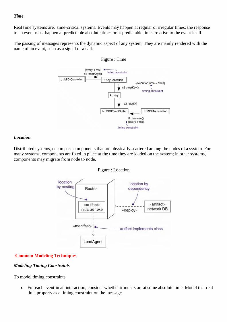
Time
Real time systems are, time-critical systems. Events may happen at regular or irregular times; the response
to an event must happen at predictable absolute times or at predictable times relative to the event itself.
The passing of messages represents the dynamic aspect of any system, They are mainly rendered with the
name of an event, such as a signal or a call.
Figure : Time
Location
Distributed systems, encompass components that are physically scattered among the nodes of a system. For
many systems, components are fixed in place at the time they are loaded on the system; in other systems,
components may migrate from node to node.
Figure : Location
Common Modeling Techniques
Modeling Timing Constraints
To model timing constraints,
For each event in an interaction, consider whether it must start at some absolute time. Model that real
time property as a timing constraint on the message.

For each interesting sequence of messages in an interaction, consider whether there is an associated
maximum relative time for that sequence. Model that real time property as a timing constraint on the
sequence.
Figure : Modeling Timing Constraint
Modeling the Distribution of Objects
To model the distribution of objects,
For each interesting class of objects in your system, consider its locality of reference. In other words,
consider all its neighbours and their locations. A tightly coupled locality will have neighbouring
objects close by; a loosely coupled one will have distant objects.
Tentatively allocate objects closest to the actors that manipulate them.
Next consider patterns of interaction among related sets of objects.
Partition sets of objects that have low degrees of interaction.
Next consider the distribution of responsibilities across the system. Redistribute your objects to
balance the load of each node.
Consider also issues of security, volatility, and quality of service, and redistribute your objects as
appropriate.
Assign objects to components so that tightly coupled objects are on the same component.
Assign components to nodes so that the computation needs of each node are within capacity. Add
additional nodes if necessary.
Balance performance and communication costs by assigning tightly coupled components to the same
node.
Figure : Modeling the Distribution of Objects

State chart Diagrams
Figure: Statechart Diagram
State chart diagram is simply a presentation of a state machine which shows the flow of control from
state to state.
State chart diagrams are important for constructing executable systems through forward and reverse
engineering.
state chart diagrams are useful in modeling the lifetime of an object
State chart diagrams commonly contain – Simple states and composite states, Transitions- including
events and actions
It is one of the five diagrams in UML for modeling the dynamic aspects of systems.
Graphically, a state chart diagram is a collection of vertices and arcs.
A state is a condition or situation in the life of an object during which it satisfies some condition, performs
some activity, or waits for some event.
An event in the context of state machines is an occurrence of a stimulus that can trigger a state transition.
A transition is a relationship between two states indicating that an object in the first state will perform
certain actions and enter the second state when a specified event occurs and specified conditions are
satisfied.
An activity is ongoing non atomic execution within a state machine.
An action is an executable atomic computation that results in a change in state of the model or the return of a
value.
A reactive or event-driven object is one whose behavior is best characterized by its response to events
dispatched from outside its context
Modeling Reactive Objects
To model a reactive object,
Choose the context for the state machine, whether it is a class, a use case, or the system as a whole.
Choose the initial and final states for the object. To guide the rest of your model, possibly state the
pre- and postconditions of the initial and final states, respectively.
Decide on the stable states of the object by considering the conditions in which the object may exist
for some identifiable period of time. Start with the high-level states of the object and only then
consider its possible substates.
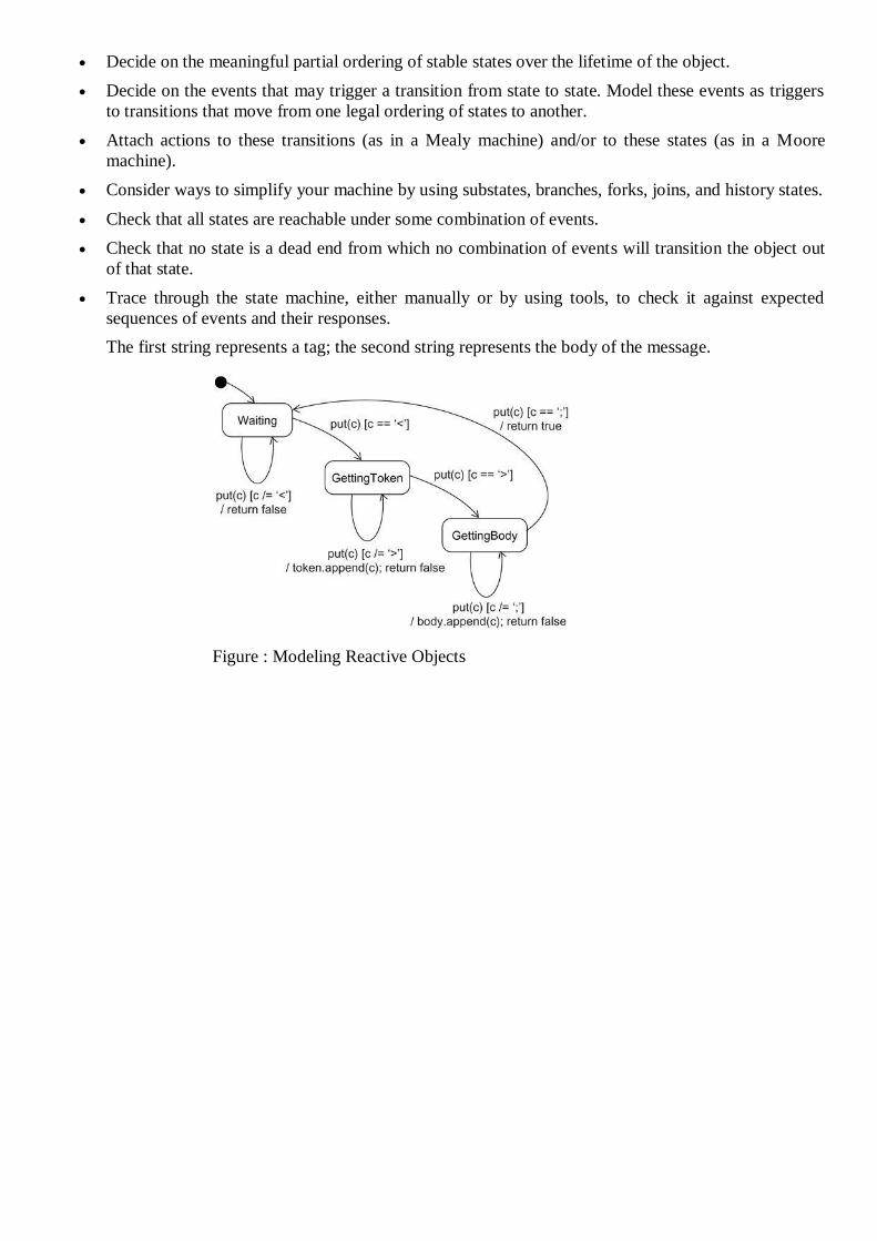
Decide on the meaningful partial ordering of stable states over the lifetime of the object.
Decide on the events that may trigger a transition from state to state. Model these events as triggers
to transitions that move from one legal ordering of states to another.
Attach actions to these transitions (as in a Mealy machine) and/or to these states (as in a Moore
machine).
Consider ways to simplify your machine by using substates, branches, forks, joins, and history states.
Check that all states are reachable under some combination of events.
Check that no state is a dead end from which no combination of events will transition the object out
of that state.
Trace through the state machine, either manually or by using tools, to check it against expected
sequences of events and their responses.
The first string represents a tag; the second string represents the body of the message.
Figure : Modeling Reactive Objects


![PRASAD V POTLURI SIDDHARTHA INSTITUTE OF … · [1] PRASAD V POTLURI SIDDHARTHA INSTITUTE OF TECHNOLOGY AUTONOMOUS AICTE approved, NBA & NAAC accredited, ISO 9001 – 2008 certified](https://img.pdfslide.net/doc/110x75/5af8575d7f8b9a44658c3d70/prasad-v-potluri-siddhartha-institute-of-1-prasad-v-potluri-siddhartha-institute.jpg)