Embed Size (px)
Citation preview

WIN A MICROCHIP REMOTE CONTROL DEMO BOARD WITH ZENA WIRELESS ADAPTOR
Teach-In 2014 Raspberry Pi – Part 3
CLASSiC-D AmpLifierConStruCting our high-power high-performAnCe Amp
plus: Net work, readout, CirCuit surgery, teChNo talk, piC N’ MiX & iNterFaCe
uSB muLti-inStrument projeCtpC controlled
2-channel digital scope
Spectrum analyser
Dmm and frequency counter
Audio function generator
EPE’s comprehensive guide to Raspberry Pi
DEC 2013 £4.40
DEC 13 Cover.indd 1 18/10/2013 09:10:33

MIKROELEKTRONIKA DEC 13.indd 1 16/10/2013 10:43:36

Everyday Practical Electronics, December 2013 1
Projects and CircuitsSix teSt inStrumentS in one tiny box 10 by Jim RoweUse this USB interface to turn your PC into a suite of test instruments
VirtinS teChnology multi-inStrument 3.2 by Jim Rowe 22Review of PC-based virtual instrument software
ClASSiC-D AmPlifier – PArt 2 28 by John ClarkeConstruction details, Loudspeaker Protection module and modes of operation
Series and featuresteChno tAlk by Mark Nelson 27Do you believe in magic?
teACh-in 2014 by Mike and Richard Tooley 40Part 3: Connecting the Raspberry Pi to the real world
mAx’S Cool beAnS by Max The Magnificent 48507 Mechanical Movements... 3D Printers... The Solidoodle3D printer... 3D Scanners
PiC n’ mix by Mike Hibbett 50PIC-ing up where we left off!
interfACe by Robert Penfold 54An 8-bit ADC for Raspberry Pi
CirCuit Surgery by Ian Bell 58Mastering rotary encoders – Part 3
net Work by Alan Winstanley 66Apped Out... Google for the nonplussed...May the Voice be with you... Network Blues
regulars and ServiceseDitoriAl 7Back to the workshop... PIC n’ Mix returns... Binders & Strips
neWS – Barry Fox highlights technology’s leading edge 8Plus everyday news from the world of electronics
miCroChiP reADer offer 21EPE Exclusive – Win a Remote Control Demo Board with ZENA Wireless Adaptor
ePe bACk iSSueS CD-rom – Did you miss these? 52
SubSCribe to ePe and save money 53
reADout – Matt Pulzer addresses general points arising 57
CD-romS for eleCtroniCS 62A wide range of CD-ROMs for hobbyists, students and engineers
DireCt book SerViCe 68A wide range of technical books available by mail order, plus more CD-ROMs
ePe PCb SerViCe 70PCBs for EPE projects
ADVertiSerS inDex 71
next month! – Highlights of next month’s EPE 72
INCORPORATING ELECTRONICS TODAY INTERNATIONAL
www.epemag.com
ISSN 0262 3617
ProJeCtS theory neWS Comment PoPulAr feAtureS
Vol. 42. no 12 December 2013
Readers’ Services • Editorial and Advertisement Departments 7
© Wimborne Publishing Ltd 2013. Copyright in all drawings, photographs and articles published in EVERYDAY PRACTICAL ELECTRONICS is fully protected, and reproduction or imitations in whole or in part are expressly forbidden.
Our January 2014 issue will be published on Thursday 5 December 2013, see page 72 for details.
Software Review
Teach-In 2014 Raspberry Pi – Part 3
Contents Dec 2013.indd 1 18/10/2013 08:44:21

,,
,
QUASAR NOV 13.indd 1 17/09/2013 15:29:03

,
,,,,
,
QUASAR NOV 13.indd 2 17/09/2013 15:29:15

F R E E C A L L O R D E R S : 0 8 0 0 0 3 2 7 241
For more details on each kit visit our website www.jaycar.co.uk
UHF Rolling Code Remote Switch KitFeatured in EPE August 2011High-security 3-channel remote control, used for keyless entry intoresidential or commercial premises or for controlling garage doors andlights. Features rolling code / code hopping, the access codes can't beintercepted and decoded by undesirables. The transmitter kit includes athree button key fob case and runs on a 12V remote control battery.The receiver is a short-form kit without case so you can mount it in thelocation or enclosure of your choice.
• Receiver 12VDC @ 150mA (1A for door strike use)• PCB: Transmitter: 34 x 56mm
Receiver: 110 x 141mmKC-5483
Additional Transmitter Kit available KC-5484 £14.50 £36.25*
Automatic Headlights Kit for CarsThis kit turns yourcar headlights onautomaticallywhen it gets dark. It can also turn the lightsoff when you park to avoid a flat battery. See website for full features.
• Kit supplied with double sided, solder-masked and screen-printed PCB, die-cast case (111 x 60 x 30mm), buzzer and electroniccomponents. Cabling not included.
KC-5524
£21.75*
Stereo Digital to AnalogueConverter KitFeatured in EPE November 2011If you listen to CDs through a DVD player, you canget sound quality equal to the best high-end CDplayers with this DAC kit. It has one coaxial S/PDIFinput and two TOSLINK inputs to which you canconnect a DVD player, set-top box, DVR, computeror any other source of linear PCM digital audio. Italso has stereo RCA outlets for connection to ahome theatre or Hi-Fi amplifier. See website for full specifications.
• Short form kit withI/O, DAC and switchPCB and on-board components only.
• Requires: PSU (KC-5418 £7.50) and toroidal transformer (MT-2086 £8.25)
KC-5487
Ultra-Low Distortion 135WRMSAmplifier ModuleFeatured in EPE August 2010This module uses the new ThermalTrak powertransistors and is largely based on the highperformance Class-A amplifier. This improved circuithas no need for a quiescent current adjustment or aVbe multiplier transistor and has an exceptionallylow distortion figure. Kit supplied with PCB and allelectronic components. Heat sink and power supplynot included.
• Output Power: 135WRMS into 8 ohms and 200WRMS into 4 ohms
• Frequency Responseat 1W: 4Hz to 50kHz
• PCB: 135 x 115mmKC-5470
£34.50*
Solar Powered Shed Alarm KitFeatured in EPE March 2012Not just for sheds, but for any location where youwant to keep undesirables out but don't haveaccess to mains power e.g. a boat on a mooring. It has 3 inputs so you can add extra sensors asrequired, plus all the normal entry/exit delay etc.Short form kit only - add your own solarpanel, SLA battery, sensors and siren.
• Supply voltage: 12VDC • Current: 3mA during
exit delay; 500µA withstandard PIR connected
• Alarm period:approximately 25 seconds to 2.5 minutes adjustable
KC-5494 £11.00*
Courtesy Interior Light Delay KitFeatured in EPE February 2007This kit provides a time delay on the car's interiorlight. It has a 'soft' fade out after a set time haselapsed, and features a much simpler universalwiring.
• Kit supplied with PCB with overlay, and allelectronic components
• Suitable for circuits switching ground or +12V or 24VDC
• PCB: 78 x 46mmKC-5392
£7.50*
Battery Saver Kit for RechargeableLithium and SLABatteriesCuts off the powerbetween the battery and load when thebattery becomes flat to prevent the battery over-discharging and becomingdamaged. Suits SLA, Li-ion, Li-Po and LiFePO4 batteriesbetween 6 to 24V. Uses very little power (<5uA) andhandles 20A (30A peak). Supplied with double sided,solder masked and screen-printed PCB with SMDs pre-soldered (apart from voltage setting resistors) and components.
• PCB: 34 x 18.5mmKC-5523
£11.00*
Everyday Practical Electronics Magazine has been publishing a series of popular kits by theacclaimed Silicon Chip Magazine Australia. These projects are 'bullet proof' and already testedDown Under. All Jaycar kits are supplied with specified board components, quality fibreglasstinned PCBs and have clear English instructions. Watch this space for future featured kits.
Featured Kits in Everyday Practical Electronics
Class-D Audio Amplifier KitHigh quality amplifier boasting 250WRMS output into 4 ohms, 150W into 8 ohms and can be bridgedwith a second kit for 450W into 8 ohms. Features include high efficiency (90% @ 4 ohm), low distortionand noise (<0.01%), and over-current, over-temperature, under-voltage, over-voltage and DC offsetprotection. Kit supplied with double sided, solder masked and screen-printed silk-screened PCB withSMD IC pre-soldered, heat sink, and electronic circuit board mounted components.
• Power requirements: -57V/0/+57V • S/N ratio: 103dB• Freq. response: 10Hz - 10kHz, +/- 1dB• PCB: 117 x 167mmKC-5514
Also available:Stereo Speaker Protector Kit to suit - KC-5515 £11.00+/- 55V Power Supply Kit to suit - KC-5517 £11.00
£32.75*
Featured this month
Featured this month
DECEMBER 2013
Can’t find the kit you arelooking for? Try the Jaycar
Kit Back CatalogueOur central warehouse keeps a quantityof older and slow-moving kits that canno longer be held in stores. A list of kitscan be found on our website. Just go to
jaycar.co.uk/kitbackcatalogue
Attention kit builders
Audio KITSNEW KITS
£50.50*
High Energy Ignition Kit for CarsUse this kit to replace a failed ignition module or to upgrade a mechanicalignition system when restoring a vehicle. Also use with any ignitionsystem that uses a single coil with points, hall effect/lumenition, reluctoror optical sensors (Crane and Piranha) and ECU.• Kit supplied with silk-screened PCB,
diecast enclosure (111 x 60 x 30mm), pre-programmed PIC and PCB mount components forfour trigger/pickup options
KC-5513
£18.25*
EPE DEC 13_EPE 18/10/13 10:20 AM Page 1
Jaycar DEC 13.indd 1 18/10/2013 08:14:52

O R D E R O N L I N E : w w w . j a y c a r. c o . u k
PHONE: 0800 032 7241*FAX: +61 2 8832 3118*EMAIL: [email protected]: P.O Box 7172, Silverwater DC NSW 1811
*Australian Eastern Standard Time(Monday - Friday 6.30am - 5.30pm)
*British Summer Time (Monday - Friday 9.30pm - 8.30am)
All prices in Pounds Sterling. Prices valid until 31/12/2013
*ALL PRICES EXCLUDE POSTAGE & PACKING
How to order
5-6 working days delivery
NOW shipping via
POST & PACKING CHARGES
Arduino Accessories
DIY Kits for Electronic Enthusiasts
Max weight: 12lb (5kg)Heavier parcels: POAMinimum order: £10
Please note: Products aredespatch from Australia, so localcustoms duty & taxes may apply.
Order Value Cost£10 - £49.99 £5£50 - £99.99 £10£100 - £199.99 £20£200 - £499.99 £30£500+ £40
Infrared Floodlight KitLet your CCD camera see in the dark! This infraredlight is powered from any 12-14VDC source anduses 32 x infrared LEDs to illuminate an area of upto 5m (will vary with light conditions).
• Kit is supplied with silkscreened/ gold plated/ solder-masked PCB, 32 x Infrared LEDs and allelectronic components
• PCB: 74 x 55mmKG-9068 Note: Not suitable forcolour CMOS cameras
£11.00*
USB Lipo ChargerCharge Li-Po cells from any USB source,USB plug pack, laptop or PC.
• 3.7V output for a single Li-Po cell• Micro-USB jack• “Charge” and “Standby” LEDs• Size: 27(W) x
16(H) x 10(D)mmXC-4243
£4.75*
USB-Serial Adaptor ModuleConnects to the USB port on your computer andacts as a virtual serial port, converting the USBsignals to either 5V or 3.3V logic level serial data.
• Size: 46(W) x 26(D)x 10(H)mm
XC-4241
£8.50*
Teach Kids Electronics
Short circuits series
PC Programmable Line Tracer KitLearn about robotics andprogramming with this line tracerkit. Run it in line tracer modeby drawing a thickdark line on paperfor the robot tofollow.
• Suitable forages 12+
• Requires 2 x AA batteries• Size: 120(L) x 64(W) x 55(H)mmKJ-8906
£11.00*
Remote Control Robot KitThis robot kit includes a collection of componentsready to assemble on the kitchen table. Oncecomplete you will have a fully remote controlledrobot unit.
• Suitable for ages: 8+• Requires 6 x AAA
batteries in total• Size: 125(H)mmapprox.KJ-8952
£11.00*
ICSP ProgrammerProgram new applications into a wide range ofmicrocontrollers using this ICSP programmer witha USB interface. Compatible with Arduinoboards, ZZ-8726 ATmega328P MCU and fullysupported by the Arduino IDE, allowing you toinstall or update Arduino-compatible boards and your own custom-made projects.
• Size: 56(L) x46(W) x 22(H)mm
XC-4237
£9.25*
Transistor Tester KitHave you ever unsoldered a suspect transistoronly to find that its OK? You can avoid thesehassles with the In-Circuit Transistor,SCR and DiodeTester. The kit doesjust that, test drivesWITHOUT the needto unsolder themfrom the circuit!
• PCB: 70 x 57mmKA-1119
£10.25*
USB Power Monitor KitPlug this kit inline with a USB device to displaythe current that is drawn at any given time.Check the total power draw from an unpoweredhub and its attached devices or what impact aUSB device has on your laptop battery life.Displays current, voltage or power, is auto-ranging and will read as low as a few microampsand up to over an amp. Kit supplied with doublesided, solder masked and screen-printed PCB withSMD components presoldered, LCD screen, and components.
• PCB: 65 x 36mmKC-5516
£21.75*
Independent Electronic Boost Controller KitIt can be used in cars fitted with factory electronic boost control using the factory control solenoid, orcars without electronic boost control using a solenoid from a wrecker etc. It has two differentcompletely programmable boost curves. This is ideal for switching between say, a race/streetmode, or a performance/wet weather mode. Each boost map has 64 points ableto be adjusted in 1% duty cycle increments. Boost curve selectionis via a dashboard switch, and it is all programmed using theHandheld Digital Controller available separate - KC-5386£24.75. Kit supplied with PCB, machined case, and allelectronic components.
• Suitable for EFI and engine management systems only.
KC-5387 £29.00*
Test & Measure Kits
Laptop not included
Batteries not included
Short Circuits - Volume 1 Acts as an introduction to electronics,NO previous knowledge of electronics is needed.
• Softcover - 96 pages BJ-8502
Short Circuits - Volume II Assumes the constructor has the basicskills and knowledge of electronics. Itcontains 20 exciting projects andintroduces the novice to soldering etc.
• Softcover - 148 pages BJ-8504
Short Circuits - Volume III This is the definitive electronics trainingmanual. After the constructors havebuilt any or all of the describedprojects, there is no reason why theywould not be able to tackle any of theconstruction projects published in theelectronic magazines.
• Softcover - 128 pages BJ-8505
Short Circuits Book and Parts Apart from the book, it alsoincludes baseboard, plentyof spring terminals and ALLthe components requiredto build every project inthe book, INCLUDING thebonus projects.
• Suitable for ages 8+ KJ-8502
Learning electronics is fun with this short circuitsbooks with their own series of construction projects.All books are geared towards specific levels ofelectronics knowledge.• Size: 205 x 275mm
£3.75*
£4.75*
£5.50*
£14.50*
EPE DEC 13_EPE 18/10/13 10:20 AM Page 2
Jaycar DEC 13.indd 2 18/10/2013 08:15:12

ESR - JULY2011 - Copy.indd 1 25/05/2011 14:53:24

Editorial Offices:EVERYDAY PRACTICAL ELECTRONICS EDITORIAL Wimborne Publishing Ltd., 113 Lynwood Drive, Merley, Wimborne, Dorset, BH21 1UUPhone: (01202) 880299. Fax: (01202) 843233.Email: [email protected]: www.epemag.comSee notes on Readers’ Technical Enquiries below – we regret technical enquiries cannot be answered over the telephone.
Advertisement Offices:Everyday Practical Electronics Advertisements113 Lynwood Drive, Merley, Wimborne, Dorset, BH21 1UUPhone: 01202 880299 Fax: 01202 843233Email: [email protected]
Editor: MATT PULZERSubscriptions: MARILYN GOLDBERGGeneral Manager: FAY KEARNGraphic Design: RYAN HAWKINSEditorial/Admin: 01202 880299Advertising and Business Manager: STEWART KEARN 01202 880299On-line Editor: ALAN WINSTANLEY
Publisher: MIKE KENWARD
READERS’ TECHNICAL ENQUIRIESEmail: [email protected] are unable to offer any advice on the use, purchase, repair or modification of commercial equipment or the incorporation or modification of designs published in the magazine. We regret that we cannot provide data or answer queries on articles or projects that are more than five years’ old. Letters requiring a personal reply must be accompanied by a stamped self-addressed envelope or a self-addressed envelope and international reply coupons. We are not able to answer technical queries on the phone.
PROJECTS AND CIRCUITSAll reasonable precautions are taken to ensure that the advice and data given to readers is reliable. We cannot, however, guarantee it and we cannot accept legal responsibility for it.
A number of projects and circuits published in EPE employ voltages that can be lethal. You should not build, test, modify or renovate any item of mains-powered equipment unless you fully understand the safety aspects involved and you use an RCD adaptor.
COMPONENT SUPPLIESWe do not supply electronic components or kits for building the projects featured, these can be supplied by advertisers.
We advise readers to check that all parts are still available before commencing any project in a back-dated issue.
ADVERTISEMENTSAlthough the proprietors and staff of EVERYDAY PRACTICAL ELECTRONICS take reasonable precautions to protect the interests of readers by ensuring as far as practicable that advertisements are bona fide, the magazine and its publishers cannot give any undertakings in respect of statements or claims made by advertisers, whether these advertisements are printed as part of the magazine, or in inserts.
The Publishers regret that under no circumstances will the magazine accept liability for non-receipt of goods ordered, or for late delivery, or for faults in manufacture.
TRANSMITTERS/BUGS/TELEPHONEEQUIPMENTWe advise readers that certain items of radio transmitting and telephone equipment which may be advertised in our pages cannot be legally used in the UK. Readers should check the law before buying any transmitting or telephone equipment, as a fine, confiscation of equipment and/or imprisonment can result from illegal use or ownership. The laws vary from country to country; readers should check local laws.
E D I T O R I A L
Back to the workshopWell, it wasn’t such a bad summer after all, but the shorter days, drizzle and distinct chill in the air heralds a new season. So, if the tan is fading and you’re feeling at a bit of a loose end it must surely be time to put away the garden furniture, dust off your oscilloscope and indulge yourselves in a new electronics project.If that appeals then you really should have a look at this month’s USB interface test instrument constructional project. A great combination of hardware and software that lets you build a Windows-based suite of test instruments: a two-channel digital scope, spectrum analyser, AC DMM and frequency counter, plus a two-channel audio signal/function/arbitrary waveform generator. It really is a very clever box of tricks that you’ll use again and again… and again! When I was doing my degree back in the 80s a decent spectrum analyser was the kind of thing you bought from Hewlett Packard for the price of a not-so-small car – but now you can build your own, and I certainly encourage you to do so.
PIC n’ Mix returnsThis issue brings the very welcome return of Mike Hibbett and his PIC n’ Mix column. We’ve all missed his writing and I’m delighted to see his clear and elegant explanations of all things PIC back in EPE.Reading his piece, my eye was caught by his comments on MakeShop, a Dubin-based shop/workshop where anyone can go and get involved with electronics – buying and making projects, as well as having access to some rather nice equipment. It sounds like a fantastic idea and I can’t help wondering if our educationalists couldn’t put a little more effort into that kind of enterprise and a little less time into constantly rearranging the syllabus or endlessly setting up new kinds of schools. Nothing beats ‘hands on’ fun and real experience-based learning for the next generation of scientists, technologists, designers and engineers. The Raspberry Pi has been a magnificent success and shows British engineers can still innovate and succeed at an international level, but we need policy makers to understand that kids being able to update a Facebook page is not an adequate substitute for real programming ability.I hope you enjoy this issue of EPE, and as ever, we welcome your feedback via the postman, email or of course our very own popular forum – Chat Zone at: www.chatzones.co.uk
Binders & StripsI am afraid to say that we will no longer be supplying binders for EPE magazines. We have now run down our stock, and due to the cost of packing and postage they are becoming very expensive to you, the customer.We are advising customers that a far more cost effective way to buy binders would be to source a supplier near to you. If you would still like the EPE logo/year labels and plastic holders that we supply, then just call us on 01202 880299 to order. The plastic holders will be supplied in bundles of 12 at a price of £5.50 (inc P&P) to the UK, and £6.00 (inc P&P) Airmail.
7
VOL. 42 No. 12 DECEMBER 2013
EPE Editorial_100144WP.indd 7 17/10/2013 19:45:32

Ray Dolby had a quiet sense of humour. When he launched Dolby S analogue noise reduction, he lec-tured the UK Institute of Broadcast
Sound. An engineer in the audi-ence asked him if there were any more, even better, systems in the pipeline.
‘I like to think we are nearing the end of the line and can stop design-ing for a while’, replied Ray Dolby. ‘It must have been like this several hundred years ago in the Scotch whisky industry. There came a time when the blenders said to them-selves, “hey, let’s stop developing, and start just enjoying the prod-uct.” And since then, everyone else has been doing just that’.
More recently, Ray Dolby talked to the Audio Engineering Society in New York. Since Dolby Labs was floated he had retired from re-search, but still needed a challenge.
So he said he learned to fly. He’d flown himself and his wife to New York from San Francisco in his
Ray Dolby (1933-2013)
A roundup of the latest Everyday News from the world of
electronics
NEWS
8 Everyday Practical Electronics, December 2013
Remembering Ray Dolby – by Barry Fox
Ray Dolby died as the HDMI Licensing Authority upgraded its
standard to carry not only Ultra HD or 4k TV, but also 32 channels of audio – which is just what’s needed to bring Dolby’s new Atmos surround system into the home. Whether we want 32-channel surround is of course another matter, and we shall never know whether Ray thought it was a good idea. He had been ill for a while and not taken any active role in Dolby Laboratories for several years. The company he founded in the UK in 1965, to market tape hiss noise reduction, has changed a lot recently and did not even send out a press alert on his death and legacy.
Dolby hiss reductionI met with Ray Dolby quite often in the early years when Decca’s studios were pioneering use of the profes-sional ‘A’ system and the consumer ‘B’ version was launched. Then came the format wars between rival types of consumer system; Dolby B, C, dbx, DNR, ANRS and Telefunk-en’s High Com. During this time I always found him patient and gen-tlemanly, never wanting to be too critical of the rival systems. He just presented the facts.
I remember his strong sense of de-cency and fair play. One year at CES in Chicago he just couldn’t under-stand why a US journalist had glee-fully revealed details of what Dolby Labs was announcing, a few hours ahead of the official press briefing.
eight-seater jet, alone and without a crew because ‘that way there’s al-ways something to think about’.
For local trips, back home in California, he flew a helicopter. ‘Aren’t they tricky things to learn to fly’, he was asked? ‘When I was a child I had no one to teach me how to ride a bike’, he recalled. ‘So I just figured it out by falling off, getting back on and trying something dif-ferent. I don’t want to offend any flight instructors, but I found learning to fly a helicopter much the same’.
Quadrulplex videoBefore starting Dolby
Labs, Ray Dolby was part of the team at Ampex that developed the Quadru-plex video recorder. It was unveiled at the Conrad Hilton Hotel in Chi-cago during the National Association of Radio and Television Broadcasters convention in April 1956. Ray Dol-by had been responsible for the FM system which Ampex adopted, in-stead of AM as previously used, and which made clear pictures possible.
Industry rumours had it that Ray’s contribution to Quad video had been undervalued in historical writings. Years ago I asked him if it was true that the essential pieces of the jigsaw had occurred to him ‘like a flash of light’. Could he ex-plain more? But he flatly refused to discuss his part in the team effort, saying ‘that can wait until after I’m dead.’ So I sincerely hope he wrote it down for us now to read.
News Dec 2013.indd 8 17/10/2013 14:48:49

Everyday Practical Electronics, December 2013 9
Sunlight is the world’s largest energy source, and the amount
available via existing technology greatly exceeds the world’s primary energy consumption. Today, solar photovoltaic (PV) technology is becoming widely accepted as an important form of power generation with over 2GW of installations contributing to the UK energy supply and projections for growth to over 20GW installed by 2020.
The Institution of Engineering and Technology’s (IET) new Code of Practice for the Design, Installation and Operation of Solar Photovoltaic Systems is set to support existing us-ers and potential consumers of the technology.
The new Code of Practice, due for publication mid-2014, will address the requirements for the design, in-stallation and operation for all scales of solar PV deployment in the UK. It will provide engineers and techni-cians with guidance on the safe, ef-fective and competent application of grid-connected solar PV systems,
The first Raspberry Pi modules were manufactured in China.
However, from September 2012, Raspberry Pi production was moved to a plant owned by Sony in Pencoed, South Wales. So, the chances are very good that any Pi bought this year will have been made here in the UK. A small, but nevertheless very welcome positive contribution to Britain’s electronics balance of trade.
DC Current Sensor
From Parallax, comes a precision amplifier for DC current
measurement. The device measures the voltage across a 0.1Ω, 1% sense resistor. Since the amplifier maximum input difference is ±320mV, this represents up to ±3.2A. The internal 12-bit ADC means the resolution at ±3.2A is 0.8mA. Advanced users can customise the unit with their own choice of sense resistor. Just remove the 0.1Ω current sense resistor and replace it with, for example a 0.01Ω resistor, to measure up to 32A with a resolution of 8mA. Priced at $9.95, the device code is 29130.
EasyVR Development Kit
The EasyVR is a multi-purpose speech recognition module
designed to add a versatile and robust speech and voice recognition capability to virtually any application. The module can be used with any host that has a UART powered at 3.3 to 5V, such as Propeller and BASIC Stamp microcontrollers. With a number of built-in speaker-independent commands, users will be able to run basic controls in six different languages (English, Italian, German, French, Spanish and Japanese). The kit includes a PWM audio output terminal that drives 8Ω speakers.
Suggested application areas include robot voice control, home automation and access control. Priced at $53.99, the device code is 30019 on the Paral-lax website: www.parallax.com
IET guidelines following increase in solar panel popularity
One million British-made Raspberry Pi boards
Yo!Bot – the mobile robot New from Parallax
including building-mounted, build-ing-integrated and ground-mounted installations.
Solar panels can be used for a va-riety of applications, including do-mestic, large roof, building facade and solar field. The IET has done extensive work on solar power, and a Solar Power Factfile produced by experts at the Institution can be found on the IET website: www.theiet.org/factfiles/energy/solar-power-page.cfm
Gadget developers BBTradesales and Zeon Tech have launched
Yo!Bot a miniature robot with a mobile brain. The mini ‘bot uses a free App and a smartphone as its intelligence. Using a PC, Mac, tablet, the Internet, an iPhone or Android smart device, users can navigate their Yo!Bot forwards, backwards and spinning both clockwise and anti-clockwise. Set the mobile device and Yo!Bot into camera mode and ‘botmasters’ can stream live videos from the Yo!bot’s field of vision back into the computer or tablet.
Yo!Bot is available from www. geniegadgets.com for around £20.95. It is compatible with Apple iPhone models 3GS, 4, 4S and 5, and also
Android phones that run Adobe AIR (for example, the Galaxy s3). It runs off four AA Batteries.
Now, the Raspberry Pi Foundation has reached an impressive landmark. The big news is that the factory in Pen-coed has made its millionth British Raspberry Pi. Add to that million the existing Chinese ones, and that makes around one and three quarter million Raspberry Pi boards in use worldwide.
To celebrate this achievement, Sony presented the millionth British Rasp-berry Pi to the Foundation in a gold-plated case.
The Yo!Bot an inexpensive and fun basis for intelligent projects on the go
News Dec 2013.indd 9 17/10/2013 16:08:54

10 Everyday Practical Electronics, December 2013
Constructional Project Constructional Project
Six test instruments in one tiny box . . . just add your PC!
With this USB interface you can turn your desktop or laptop PC into a whole suite of test instruments – a 2-channel digital scope, spectrum analyser, AC DMM and frequency counter, plus a 2-channel audio signal/function/arbitrary waveform generator.Interested? Read on.
By JIM ROWE
In this article, we present an ad-vanced multi-instrument project
with a USB interface and a Windows-based audio testing package called Multi-Instrument 3.2, developed by Singapore-based firm Virtins Tech-nology. This is a very professional software package and is reviewed elsewhere in this issue.
The interface described here is a development of the USB Recording and Replay Interface described in Sep-tember 2013 and uses the same USB CODEC. For those familiar with that design, the input channel circuitry has been changed to be more similar to that of an oscilloscope/analyser and the
output channel circuitry changed to be more like that of an AF signal/function/ arbitrary waveform generator. Both the input and output channels have also been improved in terms of bandwidth, noise floor and crosstalk.
How it worksSince the heart of this project is the same Texas Instruments/Burr-Brown PCM2902 IC, as in the September 2013 interface, we won’t give the detail of its operation. If you want to know more, refer to the September 2013 article, which gives an internal block diagram and discusses its opera-tion in detail.
For our present purposes, it’s enough to know that the PCM2902 is a single-chip stereo audio CODEC with an inbuilt full-speed USB protocol con-troller, a serial interface engine (SIE) and a USB transceiver. It provides a pair of 16-bit ADCs (analogue-to-digital converters) capable of working at seven sample rates between 8ks/s and 48ks/s and also a pair of 16-bit DACs (digital-to-analogue converters) capable of working at three sample rates: 32, 44.1 and 48ks/s.
The PCM2902 contains internal firmware that makes it fully compli-ant with the USB 1.1 standard and it installs automatically on Windows XP
USB Instrument Interface0912.indd 10 16/10/2013 10:18:44

Everyday Practical Electronics, December 2013 11
Constructional Project Constructional Project
STEREOCODEC
WITH USB SIE& TRANSCEIVER
(IC3)
REG1
USB TOHOST PC
ANTI ALIASINGLP FILTER (IC1b)
ANTI ALIASINGLP FILTER (IC2b)
ANTI ALIASINGLP FILTER (IC4a)
ANTI ALIASINGLP FILTER (IC5a)
INPUT BUFFER(IC1a)
INPUT BUFFER(IC2a)
INPUTA
INPUTB
INPUTRANGESELECT
S1a
S1b
SSPNDADC1
IN
ADC2IN
DAC1OUT
DAC2OUT
Din Dout
VbusD–D+
Dgnd
Vcc
OUTPUT BUFFER(IC4b)
OUTPUT BUFFER(IC5b)
OUTPUTRANGESELECT
OUTPUTA
OUTPUTB
S/PDIFINPUT
S/PDIFOUT
S2a
S2b
12MHz
in turn feed into the two ADC inputs of the CODEC (IC3).
The analogue ‘generator’ output channels are almost a mirror image of this configuration. The outputs of the DAC first pass through more anti-aliasing LP filters to remove any sampling ‘hash’ and are each then fed to another voltage divider/switch combination to provide three output ranges: ×1, ×0.1 and ×0.01, produc-ing maximum output signal levels of nominally 0-2.12V peak-to-peak, 0-212mV p-p and 0-21.2mV p-p. The signals from the output range switches then pass through buffer stages IC4b and IC5b to the output connectors.
Circuit detailsSo that’s the basic configuration. Now we can refer to the diagram of Fig.2 for the full circuit details.
The input circuitry for channel A is shown at upper left, while that for channel B is shown below it. Both channels are virtually identical, with channel A using the two op amps inside IC1 and channel B using those inside IC2. IC1 and IC2 are Microchip MCP6022 devices, selected because they offer impressive bandwidth, noise and distortion performance when operating from a relatively low single-supply voltage, which in our case is only 4V.
The input signals from CON1 and CON2 are fed through 1µF DC blocking capacitors to the input dividers and the
two sections of range switch S1. The signals selected by S1a and S1b then pass through 1kΩ current-limiting resistors before being applied to the inputs of IC1a and IC2a, with diodes D1/D2 and D3/D4 used to limit the voltage swing at each input to a maxi-mum of Vcc + 0.65V and a minimum of –0.65V.
Note that since the pin 3 inputs of IC1 and IC2 are biased at Vcc/2 (ie, half the supply voltage), this allows the voltage swing to be over the full supply range.
The outputs of LP filter stages IC1b and IC2b are each fed to the ADC inputs of IC3 (pins 12 and 13) via non-polarised coupling capacitors of approximately 12µF. These are made up from two series 22µF tantalum electrolytics connected in parallel with a 1µF metallised polyester capaci-tor. This has been done to extend the low-frequency response of the input channels to an acceptable level, with the modest input impedance (30kΩ) of the ADC inputs.
The S/PDIF input connector (CON3) is terminated via a 75Ω resistor. It is then connected to the digital input (pin 24) of IC3 via a 100nF coupling capacitor.
The two analogue output channels of the interface are shown at lower right in Fig.2, connected to the DAC outputs of IC3 (pins 16 and 15). Again, the two output channels are virtually identical, with IC4a and IC5a providing the LP
Fig.1: block diagram of the USB Virtual PC Instrument Interface. It’s based on a PCM2902 stereo audio CODEC with an inbuilt serial interface engine and USB transceiver.
SP3 and later versions of Windows, using the USBaudio.sys drivers.
Another nice feature of the PCM2902 is that it includes an output and an input for S/PDIF serial digital audio. It can process and analyse S/PDIF signals (from a DVD player or set-top box, for example), as well as being able to generate S/PDIF testing signals.
The basic configuration of the new interface is shown in the block dia-gram of Fig.1. It shows the PCM2902 (IC3), with its USB port at upper right. The analogue input and output circuitry is all to the left, with the two ADC inputs at upper left and the two DAC outputs at lower left. The S/PDIF input can be seen at centre left, while the S/PDIF output is shown at centre right.
Each analogue input channel has an input voltage divider and range switch which allows the input signals to be either passed straight through or attenuated to prevent overload. The input dividers and switches provide three input ranges for each channel: ×1, ×0.1 and ×0.01. This allows the input channels to handle signals of 1.7V p-p (peak-to-peak), 17V p-p and 170V p-p, respectively.
An input buffer (IC1a and IC2a) fol-lows the range switches in each input channel. These then feed the signals to anti-aliasing low-pass filters to remove any possible signal components above about 23kHz (which would cause aliasing). The outputs of the LP filters
USB Instrument Interface0912.indd 11 16/10/2013 10:18:54

12 Everyday Practical Electronics, December 2013
Constructional Project Constructional Project
8
8.2k 15k 33k
1nF820pF
82pF
680
1
3
12
2
3
4
4
5
5
67
1
1
2
2
3
3
4
4
5
5
6
6
7
7
8
8
430k
470k
1 FMKT
1 FMKT
2 x180k
2 x180k
2.2pF
2.2pF
1k
10k
10k
100
100
100
100
470k
430k
CHANNEL AINPUT
CHANNEL BINPUT
CON1
CON2
10 FTANT
1k
8.2k
8.2k
8.2k
15k
15k
15k
33k
33k
33k
1nF
1nF
1nF
820pF
820pF
820pF
82pF
82pF
82pF
220
110
680
IC1b
IC2b
IC1b
IC2b
IC1a
IC2a
IC1a
IC2a
IC4b
IC5b
IC4b
IC5b
IC4aIC4a
10 F
10 F
10 F
10 F
100nF
100nF 100nF
100nF
IC1: MCP6022
IC2: MCP6022
IC4, IC5: MCP6022
TOHOST PC
USB TYPE B
67
8
15
16
18
19
20
21
22
23
17
24
25
26
28
1.5k
1
23
4
9
10
11
12
13
14
1 F
1 F
10 FTANT
100 F
100nF
REG1 REG103GA-A
+3.6–3.85V
+5V
SSPND
IC3PCM2902
IC3PCM2902
1M
X1 12MHz
33pF 27pFAgndP AgndX
VcccI
VinL
+5V
VinR
Vcom
100nF
100nF
150nF
Vccp2I
USB VIRTUAL PC INSTRUMENT INTERFACE
1 F MKT
1 F MKT
S1a
CON3
CON4
S1b
100nFDin
S/PDIF IN
CON5
XTI
XTO
S/PDIF OUTCON6
Dout
VoutR
VoutL
47 F
47 F
1 F
1 F
CHANNEL BOUTPUT
CHANNEL AOUTPUT
22
22D–
D+
CON7
2.2
1 F
DgndU
Vbus
GND
INOUT
ENADJ
12
3,6
4
5
27
27k
13k
A
K
AgndCHID0HID1HID2
VddI
SEL0
SEL1
DGND
1 F
1 F
1 F
Vccp1I
VccXI
D51N5819
2.7k
2.7k
Vcc
Vcc
Vcc/2
Vcc/2
Vcc/2
Vcc/2
Vcc/2
Vcc/2
KA
1N5819
REG103GA-A
1
5
6
1
2814
PCM2902
10nF
IC5aIC5a
Vcc (~4.0V)
BOX & FRONT PANEL
D21N4148
D31N4148
D41N4148
D11N4148
2012SC
A
A
A
K
K
K
390
LED1
INPUTRANGESELECT
(x0.01, x0.1, X1)
TANT
TANT
12
3
4
5
6
78
Vcca
10 F
10 F
100nF
100nF
S2a
S2b
OUTPUTRANGE SELECT
(x0.01, x0.1, x1)
30k
30k
3.0k
3.0k
330
330
100k
100k
1N4148
LED
A
K
22 F*
22 F*
22 F*
22 F*
* 25V TANTALUM
MKT
MKT
22 F*22 F*
22 F*22 F*
A
K
A
K
KA
75
100 100
Vcca
L1 220 H
DIGITALGROUND
ANALOGGROUND
100
100
filtering and IC4b and IC5b forming the output buffers. IC4 and IC5 are again the same MCP6022 devices used in the input channels.
The two sections of switch S2 are used for output range switching, in conjunction with their voltage divid-ers. As with the input channels, the outputs of IC4a and IC4b are coupled to their respective dividers via 12µF coupling capacitors, to achieve an acceptable low-frequency response. That’s also the reason for the 47µF
capacitors used to couple the outputs of IC4b and IC5b to output connectors CON4 and CON5. The 680Ω resistors connected in series with each output provide short-circuit protection.
The S/PDIF digital output of IC3 (pin 25) is coupled to output connector CON6 via a 150nF capacitor and two resistors, selected to give the S/PDIF output a source impedance very close to the correct value of 75Ω.
As with the September 2013 Inter-face, the USB port of the PCM2902
CODEC (IC3) connects to the USB host connector CON7 via the rec-ommended component values. The power for all of the interface circuitry is derived from the Vbus pin (1) of CON7, but is connected to the rest of the circuit via REG1, a REG103GA low dropout (LDO) regulator, which can be enabled or disabled via its EN input (pin 5).
This is done so that the current drain of the interface can be switched down to a very low value when the host
Fig.2: the complete circuit diagram of the USB interface unit. IC1a and IC1b, and IC2a and IC2b are the input buffers and low-pass filters for the Channel A and Channel B inputs, while IC4a and IC4b, and IC5a and IC5b provide filtering and buffering for the output signals. IC3 is the stereo audio CodeC – it provides the ADC and DAC stages, generates the USB signals and handles S/PdIF input and output signals.
USB VIRTUAL PC INSTRUMENT INTERFACE
USB Instrument Interface0912.indd 12 16/10/2013 10:19:04

Everyday Practical Electronics, December 2013 13
Constructional Project Constructional Project
8
8.2k 15k 33k
1nF820pF
82pF
680
1
3
12
2
3
4
4
5
5
67
1
1
2
2
3
3
4
4
5
5
6
6
7
7
8
8
430k
470k
1 FMKT
1 FMKT
2 x180k
2 x180k
2.2pF
2.2pF
1k
10k
10k
100
100
100
100
470k
430k
CHANNEL AINPUT
CHANNEL BINPUT
CON1
CON2
10 FTANT
1k
8.2k
8.2k
8.2k
15k
15k
15k
33k
33k
33k
1nF
1nF
1nF
820pF
820pF
820pF
82pF
82pF
82pF
220
110
680
IC1b
IC2b
IC1b
IC2b
IC1a
IC2a
IC1a
IC2a
IC4b
IC5b
IC4b
IC5b
IC4aIC4a
10 F
10 F
10 F
10 F
100nF
100nF 100nF
100nF
IC1: MCP6022
IC2: MCP6022
IC4, IC5: MCP6022
TOHOST PC
USB TYPE B
67
8
15
16
18
19
20
21
22
23
17
24
25
26
28
1.5k
1
23
4
9
10
11
12
13
14
1 F
1 F
10 FTANT
100 F
100nF
REG1 REG103GA-A
+3.6–3.85V
+5V
SSPND
IC3PCM2902
IC3PCM2902
1M
X1 12MHz
33pF 27pFAgndP AgndX
VcccI
VinL
+5V
VinR
Vcom
100nF
100nF
150nF
Vccp2I
USB VIRTUAL PC INSTRUMENT INTERFACE
1 F MKT
1 F MKT
S1a
CON3
CON4
S1b
100nFDin
S/PDIF IN
CON5
XTI
XTO
S/PDIF OUTCON6
Dout
VoutR
VoutL
47 F
47 F
1 F
1 F
CHANNEL BOUTPUT
CHANNEL AOUTPUT
22
22D–
D+
CON7
2.2
1 F
DgndU
Vbus
GND
INOUT
ENADJ
12
3,6
4
5
27
27k
13k
A
K
AgndCHID0HID1HID2
VddI
SEL0
SEL1
DGND
1 F
1 F
1 F
Vccp1I
VccXI
D51N5819
2.7k
2.7k
Vcc
Vcc
Vcc/2
Vcc/2
Vcc/2
Vcc/2
Vcc/2
Vcc/2
KA
1N5819
REG103GA-A
1
5
6
1
2814
PCM2902
10nF
IC5aIC5a
Vcc (~4.0V)
BOX & FRONT PANEL
D21N4148
D31N4148
D41N4148
D11N4148
2012SC
A
A
A
K
K
K
390
LED1
INPUTRANGESELECT
(x0.01, x0.1, X1)
TANT
TANT
12
3
4
5
6
78
Vcca
10 F
10 F
100nF
100nF
S2a
S2b
OUTPUTRANGE SELECT
(x0.01, x0.1, x1)
30k
30k
3.0k
3.0k
330
330
100k
100k
1N4148
LED
A
K
22 F*
22 F*
22 F*
22 F*
* 25V TANTALUM
MKT
MKT
22 F*22 F*
22 F*22 F*
A
K
A
K
KA
75
100 100
Vcca
L1 220 H
DIGITALGROUND
ANALOGGROUND
100
100
PC’s USB controller indicates to the CODEC’s serial interface engine (SIE) that it should go into ‘suspend’ mode.
When the SSPND output of IC3 (pin 28) rises to a high logic level to indicate the end of suspend mode, REG1 is turned on and delivers sup-ply voltage (Vcc – approximately 4.0V) to the rest of the circuit – in-cluding the ADC and DAC circuitry inside IC3 itself. This receives a supply voltage of around 3.8V, via Schottky diode D5.
LED1 is driven from the Vcc line via a 390Ω resistor. LED1 indicates when the Interface has been activated (it re-mains off in suspend mode), as well as serving as a power-on indicator when the Interface is in use.
L1 is used to provide a connection between the digital and analogue grounds within the circuit – a connec-tion which represents a low imped-ance at low frequencies but a higher impedance at high frequencies. This helps to keep digital hash out of the
analogue sections of the circuit and im-proves the overall noise performance.
ConstructionAll the parts used in the USB Inter-face are mounted on a double-sided PCB coded 24109121 and measuring 160mm × 109mm, available from the EPE PCB Service. This fits inside a diecast aluminium box measuring 171mm × 121mm × 55mm, to provide physical protection as well as effective shielding.
USB Instrument Interface0912.indd 13 16/10/2013 10:19:17

14 Everyday Practical Electronics, December 2013
Constructional Project Constructional Project
USB VIRTUAL INSTRUMENT INTERFACE
AGND
DGND
TOP
24109121C 2012
VinB
VinA
10 F
100nF
100 F+
22 F
22 F
22 F
22 F
LED1
CON6
SPDIF
CON3
SPDIFCON5
CHAN B OUT
CON2CHAN B IN
CON1CHAN A IN
CON4
CHAN A OUT
47 F
10 F
110220
150nF
100nF
D5
10 F
10 F
100nF1 F
1 F
220
H
1M
1 F
10nF
390
22F
22F
10 F
10 F
13k
22
27k
10 F680
3.0k
22
100
100
2.7k
10k
1 F
1 F
82pF
1nF
22 F
22 F
820p
F
1nF
1k
12.0MHz82pF
1nF8.2k
100
100100
1nF
820p
F
47 F
430k
75
180k
100
180k
180k
430k
180k
330
100k
470k
470k
10 F
30k
100nF
8.2k15
k
30k
1k
15k
8.2k
8.2k
15k
15k
33k
33k
10k
3.0k
820p
F
820p
F
82pF
82pF
100
100
2.2p
F
2.2p
F
100n
F
33pF27pF
33k
1 F
1 F
1 F
1 F 1 F
2.7k
33k
1.5k
330
2.2
680100k
1 F
1 F
100nF
100nF
100n
F
100nF
REG
103
S2
OUTPUT
S1
INPUT
D1
D2
D3
D4
100nFDgnd
Agnd
VinB
VinA
RANGE
+
+
+
++
+ +
++
+
KA
OUTIN
+
+
+
+
+
+
+
+ +
+
+
RANGE
+
+
+58
19
4148
4148
4148
4148
IC4
IC4
MC
P602
2M
CP6
022
IC5
IC5
MC
P602
2M
CP6
022
IC2
IC2
MC
P602
2M
CP6
022
IC1
IC1
MC
P602
2M
CP6
022
IC3IC3PCM2902PCM2902
REG1REG1
4 3
21
CON7
TO HOSTUSB (B)
X1
The PCB is mounted on four M3 × 25mm tapped spacers behind the lid of the box. The spindles of switches S1 and S2 pass through matching holes in the lid, as does the body of LED1.
USB connector CON7 is mounted at the rear of the PCB, and when the PCB and lid are fitted to the box, CON7 is ac-cessed via a rectangular hole in the rear. All of the other I/O connectors (CON1-CON6) are mounted along the front of the PCB, with the input sockets to the left and the output sockets to the right.
These all pass through matching holes at the front of the box, when the PCB and lid are fitted. Hence, there is no wiring at all, apart from a single lead which connects the metal box to the earth of the PCB.
Fig.3 shows the parts layout on the PCB. You should follow it closely re-garding the placement and orientation of the various components.
Begin the PCB assembly by fitting the two SMD components, IC3 and
Fig.3: install the parts on the PCB as shown here, starting with the surface-mount device IC3. Note that this layout shows the tracks on the top side of the PCB only; the tracks on the bottom have been omitted for clarity.
The PCB and lid assembly is slipped into the case as shown here. Don’t
forget to file away the metal lip at the top front of the case.
The unit is built into a diecast
metal case that provides
necessary shielding.
USB Instrument Interface0912.indd 14 17/10/2013 13:36:49

Everyday Practical Electronics, December 2013 15
Constructional Project Constructional Project
REG1 (it’s easier to solder these in place when none of the other compo-nents are installed). Use a temperature-regulated iron with a fine chisel or conical point and hold each device in position carefully using a toothpick or similar tool while you tack-solder two pins that are well separated from each other.
These will hold the device in posi-tion while you solder the rest of the pins; make sure that the originally tacked pins are properly soldered as well. Don’t worry if you accidentally create solder bridges between adjacent pins – these are almost inevitable and can be removed at the end of the soldering procedure using fine solder wick braid (an illuminated magnifier is handy when it comes to checking for solder bridges).
Once IC3 and REG1 are installed, you can fit the various passive com-ponents, starting with the resistors. These should be all 0.25W 1% metal film types, with the exception of the 2.2Ω unit just below CON7. This one needs to be a 0.5W or 0.625W type. Fit the 220µH RF inductor (L1) at this stage as well, just below CON7.
Now fit the various capacitors. Make sure that you don’t confuse the 10µF tag tantalum types with the 10µF alu-minium electrolytics and take care to
fit all of these polarised components the correct way around. To help in this regard, Fig.3 shows the tantalum capacitors in brown, while the alu-minium electros are shown as circles filled with pale blue.
After all of the capacitors are in place you can install the 12MHz clock crystal for IC3, which fits just to the front of IC3 and alongside the 1MΩ biasing resistor.
Next, install the 1N4148 diodes (D1-D4), which are located just to the left of the sockets for IC1 and IC2. The last diode to fit is D5 (1N5819) which goes midway between IC3 and REG1.
The input and output connectors (CON1-CON7) are next. Then fit the 8-pin sockets for IC1, IC2, IC4 and IC5, taking care to orient them with their notched ends towards the rear of the board, as shown in Fig.3.
Switches S1 and S2 can now be installed. Before you fit them, their spindles should be cut to a length of 16mm so they’ll protrude through the front panel by the correct amount when the board assembly is fitted to it. The plastic spindles can be cut quite easily using a hacksaw and any burrs smoothed off using a small file. Then the switches can be fitted to the board. Orient them as shown in Fig.3, with their spigots at 11 o’clock. Press them
down firmly against the top of the PCB and then solder all of their pins to the pads underneath.
Now try turning the switch spindles to check that they are correctly set for three positions. If not, you’ll need to first rotate each switch fully anticlockwise, then remove the nut and lock-washer before lifting up the stop pin washer and refitting it with the pin passing down into the correct hole (ie, between the moulded 3 and 4 nu-merals). Finally, refit the lockwasher and nut to hold everything in place.
The final component is LED1, located just below the centre of the board with its cathode ‘flat’ towards the right. It is mounted in the upright position, with the lower surface of its body about
24mm above the top surface of the board. Just tack-solder one lead to hold the LED in place while the board is fitted behind the box lid.
You will be able to adjust the height of the LED later, so that it protrudes nicely through the front panel. Both solder joints can be finalised then.
The last step in completing the PCB assembly is to plug the four MCP6022 ICs into their sockets, each one with its notch end towards the rear of the board and also making sure that none of their pins become buckled. It’s also a good idea to earth yourself before handling them, because they can be damaged by electrostatic discharge.
Preparing the lid and the boxBefore the completed PCB assembly can be attached to the box lid, you’ll need to drill holes in the lid to match the screws for the mounting spacers. In addition, you need to drill clearance holes for LED1 and the spindles of S1 and S2. The locations and sizes of all of these holes are shown in Fig.4, which is reproduced actual size so it can be used as a drilling template if you wish. As you can see, there are only seven holes to be drilled in all, so preparing the lid is quite easy.
The drilling diagram for the box is shown in Fig.5. Six holes need to be
This view shows the completed PCB, ready for installation on the case lid. Be sure to install the two switches with their spigots at 11 o’clock, as shown on Fig.3.
USB Instrument Interface0912.indd 15 17/10/2013 13:40:05

16 Everyday Practical Electronics, December 2013
Constructional Project Constructional Project
(REAR OF BOX)
(FRONT OF BOX)
CL
13
149.5
5
1111
15 1523 23 2323
A A B B A A
HOLES A ARE 14mm DIAMETER HOLES B ARE 12mm DIAMETER HOLE C IS 3mm DIAMETER ALL DIMENSIONS IN MILLIMETRES
18
30
15
10
UPPER LIP NEEDS TO BE FILED OFF ALONG FRONT OF BOX (SEE TEXT)
C
CL
CL
73.5 73.5
42
42
49.5 49.5
1419
A A
A A
B
C C
(LID OF 170 x 120 x 66mm DIECAST BOX)
HOLES A ARE 3.0mm DIAMETERHOLE B IS 3.5mm DIAMETERHOLES C ARE 6.5mm DIAMETER
ALL DIMENSIONS IN MILLIMETRES
Fig.4: this is the full-size drilling template for the case lid.
Fig.5: the drilling templates for the front and rear panels of the case. The square hole can be made by drilling a series of small holes around the inside perimeter, then knocking out the centre piece and filing the job to the shape.
USB Instrument Interface0912.indd 16 16/10/2013 10:19:57
Everyday Practical Electronics, December 2013 17
Constructional Project Constructional Project
+ +22 F 22 F
(LID OF BOX)
BOARD ATTACHED TO REAR OF LIDVIA 4 M3 x 25mm TAPPED SPACERS
PCB
BNC INPUT& OUTPUT
CONNECTORSUSB TYPE B
CONNECTOR
4 M3 x 9mmSCREWS
4 M3 x 6mmSCREWS
SWITCH SHAFTS PASS UPTHROUGH 6.5mm DIAMETER HOLES
+47 F
SUPPORT SPACERIN RIGHT REAR
PCB
LOCKWASHERBETWEEN SOLDER
LUG & PCB
LOCKWASHERSON EITHER SIDEOF SOLDER LUG
LOCKWASHERSON EITHER SIDEOF SOLDER LUG
RIGHT REARCORNER OF BOX
RIGHT REARCORNER OF BOX
BOX EARTHINGWIRE
drilled using a pilot drill and then carefully enlarged to the correct size using a tapered reamer. The rectangu-lar hole for USB connector CON7 can be made by drilling a series of small holes around the inside perimeter, then knocking out the centre piece and filing the job to the final rectangular shape.
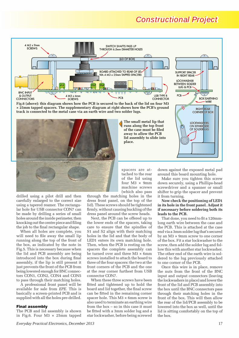
When all holes are complete, you will need to file away the small lip running along the top of the front of the box, as indicated by the note in Fig.5. This is necessary because when the lid and PCB assembly are being introduced into the box during final assembly, if the lip is still present it just prevents the front of the PCB from being lowered enough for BNC connec-tors CON1, CON2, CON4 and CON5 to pass through their matching holes.
A professional front panel will be available for sale from EPE. This is basically a screen-printed PCB and is supplied with all the holes pre-drilled.
Final assemblyThe PCB and lid assembly is shown in Fig.6. Four M3 × 25mm tapped
spacers are at-tached to the rear of the lid using four M3 × 9mm machine screws (which also pass
through the matching holes in the dress front panel, on the top of the lid). These screws should be tightened firmly, without causing buckling of the dress panel around the screw heads.
Next, the PCB can be offered up to the lower ends of the spacers, taking care to ensure that the spindles of S1 and S2 align with their matching holes in the lid and that the body of LED1 enters its own matching hole. Then, when the PCB is resting on the spacers the complete assembly can be turned over and three M3 × 6mm screws installed to attach the board to three of the four spacers: the two at the front corners of the PCB and the one at the rear corner furthest from USB connector CON7.
When these three screws have been fitted and tightened up to hold the board and lid together, the final screw can be fitted in the remaining corner spacer hole. This M3 × 6mm screw is also used to terminate an earthing wire from the box – so in this case it must be fitted with a 3mm solder lug and a star lockwasher, before being screwed
down against the exposed metal pad around this board mounting hole.
Make sure you tighten this screw down securely, using a Phillips-head screwdriver and a spanner or small shifter to grip the spacer and prevent it from turning.
Now check the positioning of LED1 in its hole in the front panel. Adjust it if necessary before soldering both its leads to the PCB.
That done, you need to fit a 120mm-long earth wire between the case and the PCB. This is attached at the case end via a 3mm solder lug that’s secured by an M3 × 9mm screw to one corner of the box. Fit a star lockwasher to the screw, then add the solder lug and fol-low this with another star lockwasher. The other end of the earth wire is sol-dered to the lug previously attached to one corner of the PCB.
Once this wire is in place, remove the nuts from the front of the BNC input and output connectors (leaving the lockwashers in place) and lower the front of the lid and PCB assembly into the box until the BNC connectors pass through their matching holes in the front of the box. This will then allow the rear of the lid/PCB assembly to be lowered into the box as well, until the lid is sitting comfortably on the top of the box.
Fig.6 (above): this diagram shows how the PCB is secured to the back of the lid on four M3 × 25mm tapped spacers. The supplementary diagram at right shows how the PCB’s ground track is connected to the metal case via an earth wire and two solder lugs.
The small metal lip that runs along the top front of the case must be filed away to allow the PCB lid assembly to slide into place.
USB Instrument Interface0912.indd 17 16/10/2013 10:20:10

18 Everyday Practical Electronics, December 2013
Constructional Project Constructional Project
The lid can now be secured in place using four M4 screws (supplied with the box). Finally, refit the BNC connec-tors with their mounting nuts and then fit the knobs to the spindles of S1 and S2. Your Virtual Instrument Interface is now complete.
Checkout timeThe only setting up adjustments you may need to make are in the operating system of the PC, as explained shortly. Checking out the Interface basically involves little more than connecting it to a spare USB port on either the PC
itself or to a spare downstream port on an external hub connected to it.
Because the PCM2902 CODEC in-cludes firmware which identifies itself as a ‘Generic USB Audio CODEC’, it usually installs automatically when you connect it to a PC running Win-dows XP (SP3), Vista or Windows 7.
After a few seconds, you should hear a greeting from the PC’s sound system to indicate that the operating system has recognised that a new Plug and Play USB device has been connected. It then shows pop-ups from the System Tray as it identifies the device and automatically installs the standard USB audio drivers for it. LED1 on the Interface should also light as soon as the drivers are installed.
The next step is to check that this has all taken place correctly. In Windows XP, click the Start button, launch the Control Panel and double click on ‘Sounds and Audio Devices’. This should bring up the Sounds and Audio Devices Prop-erties dialog. If you then click on the ‘Audio’ tab you should see ‘USB Audio CODEC’ listed in the drop-down device selection lists for both Sound Playback and Sound Recording. This should also be the case if you click on the ‘Voice’ tab.
Now click on the ‘Hardware’ tab and select ‘USB Audio Device’. You should see the following information in the Device Properties area:
PC Instrument Interface: Parts List
1 diecast aluminium box, 171mm × 121mm × 55mm
1 PCB, available from the EPE PCB Service, code 24109121, size160mm × 109mm
1 front panel PCB, code 241091221 12.00MHz HC49U/US crystal (X1)1 220µH RF choke, axial leads (L1)2 4-pole 3 position rotary
switches (S1,S2)4 PCB-mount BNC connectors
(CON1-CON2, CON4-CON5)2 PCB-mount switched RCA
sockets (CON3, CON6)1 USB type-B connector, PCB-
mount (CON7)4 8-pin DIL sockets, machined pin
type2 instrument knobs, 24mm dia.4 M3 x 25mm tapped spacers5 M3 x 9mm machine screws4 M3 x 6mm machine screws1 M3 nut2 3mm solder lugs3 3mm star lockwashers1 120mm-length of insulated
hookup wire
Semiconductors4 MCP6022 dual op amps
(IC1,IC2,IC4,IC5)1 PCM2902 audio CODEC (IC3)
(Element14 8434700)1 REG103GA-A low-dropout
regulator (REG1) (Element14 1207256)
1 3mm high-intensity red LED (LED1)
4 1N4148 100mA diodes (D1-D4)1 1N5819 1A Schottky diode (D5)
Capacitors1 100µF 16V RB electrolytic2 47µF 16V tantalum electrolytic8 22µF 16V tantalum electrolytic6 10µF 16V RB electrolytic2 10µF 16V tantalum electrolytic6 1µF monolithic ceramic6 1µF MKT polyester1 150nF MKT polyester10 100nF MKT polyester1 10nF MKT polyester4 1nF polyester (greencap)4 820pF 50V disc ceramic4 82pF 50V disc ceramic1 33pF 50V NP0 disc ceramic1 27pF 50V NP0 disc ceramic2 2.2pF 50V NP0 disc ceramic
Resistors (0.25W, 1%)1 1MΩ 2 2.7kΩ2 470kΩ 1 1.5kΩ2 430kΩ 2 1kΩ4 180kΩ 2 680Ω2 100kΩ 1 390Ω4 33kΩ 2 330Ω2 30kΩ 1 220Ω1 27kΩ 1 110Ω4 15kΩ 8 100Ω1 13kΩ 1 75Ω2 10kΩ 2 22Ω4 8.2kΩ 1 2.2Ω 0.5W2 3.0kΩ
Note: the PCB and front panel are available from EPE.
The PCM2902 IC specified in this project (and the USB Stereo Recording/Playback Interface from September 2013) is the most common type currently available. However, Texas Instruments also has two newer versions of this chip: the PCM2902B and PCM2902C.
All three versions are pin-compatible and should work without any circuit changes. The later versions have some minor advan-tages: (1) the B and C versions are USB 2.0 compliant, whereas
the original is only USB 1.1 compliant; (2) the original chip had a one-sample recording delay between the left and right channels which has been fixed in the later revisions; and (3) the later versions are more tolerant of malformed S/PDIF input data. In addition, the PCM2902C identifies its analogue inputs as line level inputs rather than microphone inputs, so you don’t have to adjust the input gain before using it. It also has an onboard digital volume control.
PCM2902 version differences
USB Instrument Interface0912.indd 18 16/10/2013 10:20:19

Everyday Practical Electronics, December 2013 19
Constructional Project Constructional Project
Manufacturer: (Generic USB Audio)Location: Location 0 (USB Audio CODEC)Device Status: This device is work-ing properly.
If you are using Windows 7, launch the Control Panel and select ‘Hard-ware and Sound’. Then double-click on ‘Sound’, which should bring up the dialog box shown in Fig.7. The ‘Playback’ tab will be automatically selected, showing that the default playback device (labelled ‘Speakers’) is the ‘USB Audio CODEC’.
If you then select the Recording tab, this should show that the default record-ing device (labelled ‘Microphone’) is again the USB Audio CODEC, as shown in the upper dialog in Fig.8. If you then click on the Microphone to select it and then click on the Properties button, this will open up the Microphone Properties dialog (the lower one in Fig.8), to con-firm that the Interface is installed as a Generic USB Audio device.
Features and specificationsA 2-channel virtual test instrument USB interface to suit to any Windows-based PC, powered from the PC’s USB port. The two input channels and two output chan-nels can all operate simultaneously. Also provided is an S/PDIF input and output.
When used in conjunction with a suitable software package the Interface allows the PC to be used as a 2-channel audio DSO and spectrum analyser combined with an AC DMM and a frequency counter, plus a 2-channel AF signal and func-tion generator able to provide low-distortion sinewaves, a number of standard waveforms, white and pink noise, arbitrary waveforms and even DTMF signals and musical tones. Features of the Interface include:
• Input channels provide three switched sensitivity levels: x1.0, x0.1 and x0.01
• Nominal input sensitivity (x1.0 range) is 500mV RMS (1.414Vp-p/-3.8dBu).
• Maximum input level (x1.0 range) before clipping is 600mV RMS (1.70Vp-p/-2.2dBu).
• Input impedance (both channels) is 1MΩ//20pF.
• Effective noise floor of the input channels is at –99dBu (2.5µV).
• Two high-quality 16-bit ADCs capable of operating at sampling rates of 8, 11.025, 16, 22.05, 32, 44.1 and 48ksamples/s.
• Frequency response of input channels is as follows: 21Hz – 8kHz +0/–0.15dB 12Hz – 12.6kHz +0/–0.5dB 6Hz – 16.3kHz +0/–1.0dB 1.5Hz – 20kHz +0/–2.0dB <1Hz – 22kHz +0/–3.0dB
• Output channels provide three switched output levels: x1.0, x0.1 and x0.01.
• Nominal output level on the x1.0 range is 500mV RMS (1.414Vp-p/–3.8dBu).
• Maximum output level (x1.0 range) before clipping is 750mV RMS (2.12Vp-p/–0.28dBu).
• Output impedance (both channels) is 675Ω.
• Two high quality 16-bit DACs capable of operating at sampling rates of 32, 44.1 and 48ksamples/s.
• Frequency response of the output channels is as follows: 4.6Hz – 17.0kHz +0.15dB/–0.5dB 3.1Hz – 18.7kHz +0.15dB/–1.0dB 1.2Hz – 20.5kHz +0.15dB/–2.0dB <1Hz – 22.0kHz +0.15dB/–3.0dB• Crosstalk between channels, overall: below –62dB from 20Hz – 5kHz below –59dB from 1Hz – 10kHz below –56dB from 10kHz – 20kHz
• Crosstalk between output and input channels: as for between channels shown above
• THD+N for both channels, overall (ie, output-> input) for output/input levels of 0.5V RMS: at 100Hz, 0.075%; at 1kHz, 0.075%; at 5kHz, 0.1%
• S/PDIF input and output both handle 16-bit stereo signals at sampling rates of 32, 44.1 and 48ks/s.
• Fully compliant with the USB 1.1 specification
• Installs automatically on Windows XP SP3 and later Windows operating systems (plus Mac and Linux systems) using the standard USBaudio.sys drivers – no special or custom drivers required.
• Fully compatible with Windows-based Virtual Instrument software such as Virtins MI 3.2 (standard and Pro versions).
• Low current drain from PC via USB cable: less than 65mA
The earth track of the PCB is connected to the metal case using a short earthing wire. This can be run to the right-rear of the case (not the left rear as shown here).
The earth track of the PCB is connected to the metal case using a short earthing wire. This can be run to the right-rear of the case (not the left rear as shown here).
Fig.7: the Windows 7 Sound dialog box. The default playback device should be the ‘USB Audio CODEC’.
Reproduced by arrangement with SILICON CHIP
magazine 2013.www.siliconchip.com.au
USB Instrument Interface0912.indd 19 16/10/2013 10:20:30

20 Everyday Practical Electronics, December 2013
Constructional Project Constructional Project
Finally, you need to select the Lev-els tab at the top of the Microphone Properties dialog. This will display the Microphone mixer level control slider, as shown in Fig.9. Move the slider towards the lefthand end until the number displayed in the box to its right is ‘4’ (see Fig.9).
This is the correct setting for our Virtual Instrument Interface, because the PCM2902 leads Windows to be-lieve it is providing amplified signals from two microphones when it’s really providing ‘line level’ inputs. By setting the slider to ‘4’, we trick Windows into believing the signals are effectively coming from line level inputs.
Once you have set the ‘Micro-phone’ slider to 4, all that is neces-sary is to back out of these dialogs by clicking on the ‘OK’ buttons in turn until you return to the Control
Fig.9 selecting the Levels tab in Fig.8 brings up this dialog box. The Microphone slider control should be dragged to the left to give a level reading of ‘4’ (see text).
Fig.8: the default recording device (left) should again be shown as the ‘USB Audio CODEC’. Clicking the Properties button then brings up the dialog shown below.
These two scope grabs show waveforms generated by the Virtins’ Multi-Instrument 3.2 software and processed through the Virtual PC Instrument Interface. A 10kHz sinewave is shown at left, while at right is a 100Hz square wave.
Panel. This can then be closed and your Virtual Instrument Interface will now be installed and ready for use. Of course before you can do so, you’ll need to install the Virtual Instrument Software you’re planning to use with it. For details on installing and using Virtins’ Multi-Instrument 3.2 please refer to the review article elsewhere in this issue.
The USB socket is accessed via a square hole in the rear side panel of the case. Note that the case lid is held on using just four screws (one at each corner). The other two holes in the lid are covered by the front panel and are not used.
USB Instrument Interface0912.indd 20 16/10/2013 10:20:46


Everyday Practical Electronics, December 2013 23
Software Review Software Review
2-channel spectrum analyser – a selec-tion of seven different display modes: amplitude/power spectrum, phase spectrum, auto correlation and cross correlation functions, coherence func-tion, transfer function (Bode plot) and impulse response. The FFT window size can be selected from 16 different options, from 128 to 4,194,304 points, while there is a choice of no less than 55 different windowing functions, including rectangular, triangular, Han-ning, Hamming, Blackman, Gaussian, cosine, Poisson and so on.
The overlap between windows can also be set to any desired percentage, and there’s a choice of many different display and scaling options for both the Y axis and the frequency axis. Param-eters which can be measured using the spectrum analyser include bandwidth, crosstalk, THD, THD+N, SINAD, SNR and noise level (NL) in a specified frequency band. It’s also possible to measure IMD (SMPTE/DIN, CCIF etc).
2-channel digital signal generator – a wide choice of waveforms and as-sociated functions, including sine, rectangle (with adjustable duty cycle), triangle, sawtooth and multi-tones like DTMF. There’s also a choice of white or pink noise, maximal-length sequences with length adjustable between 127 and 16,777,215 samples, unit impulse and unit step, notes from the tempered musical scale and arbitrary waveforms (which may be stored on hard disk).
In addition, the generator can be set to provide any desired phase differ-ence between the two output channels, and it can mask their outputs in order to provide ‘burst’ test signals. It can also provide sinewave signals sweep-ing either linearly or logarithmically between any two selected frequencies and at any desired speed.
It’s also possible to set the exact output frequency to a value which minimises ‘spectral leakage’ when you are using the spectrum analyser.
AC multimeter – able to display RMS volts, dBV, dBu, dBrelative and dBA/B/C, plus cycle RMS and cycle mean. It can also function as a frequency counter, a tachometer (RPM), a straight counter, a duty cycle indicator and a frequency/voltage converter.
Calibration and compensationVMI 3.2 also supports calibration of the input and output channels of your
interface/sound card, so that absolute values in engineering units can be used for display, analysis or export. It is also able to account for external attenuator settings (such as the input switch settings in the Virtual Instru-ment Interface), as well as being able to compensate for hardware character-istics such as the frequency response deviations of the interface/sound card. Once measured, these can be saved as ‘reference curves’ and loaded in whenever they are needed.
Zooming and scrolling in both the X and Y axes are supported in all graphs displayed by the scope and spectrum analyser, to allow inspection of fine details. In any case, VMI 3.2 provides a ‘cursor reader’ for each graph, al-lowing you to determine the exact X and Y readings for any specific point just by clicking on it and holding the mouse button down. There are also two markers which can be set by dou-ble clicking, for comparison purposes.
Another nice feature of VMI 3.2 is a row of 16 ‘hot panel setting’ buttons along the top of the screen. These are pre-configured to set up all the in-strument panel controls and settings for specific tests. However, you are free to reconfigure any or all of these
buttons as you wish, for your own most-frequently performed tests. As part of the reconfiguring, you are even able to change the legend on the button being ‘reprogrammed’.
It’s also quite easy to save any de-sired screen layout and combination of instrument settings as the default ‘skin’ for VMI 3.2 when you start it up each time. In short, it offers a high degree of customisation.
All data collected by the VMI 3.2 oscilloscope or spectrum analyser can be saved, either as a wave file or a text file. All graphs can also be exported as bitmap (.BMP) files or printed out directly. And waveform files saved in either .WAV or .TXT form can be im-ported into the Generator to generate that waveform again.
System requirementsVMI 3.2 is compatible with all versions of Windows from Windows 95 to Win-dows 7, either 32-bit or 64-bit. Virtins suggest that for optimum results, your monitor should have a horizontal reso-lution of at least 1024 pixels.
As you’ve no doubt gathered from the above, VMI 3.2 has an almost bewildering array of functions and facilities. Fortunately, there is a 283-
Fig.1: the main screen has four horizontal function bars along the top, with icons to activate the scope, spectrum analyser, DMM and generator. Here, the scope window is at upper left, with the analyser window below it. The smaller, narrower window at lower right is for the signal generator.
Virtins MultiInstrument Review.indd 23 16/10/2013 10:21:59

24 Everyday Practical Electronics, December 2013
Software Review Software Review
page user manual which can be down-loaded in PDF format. And there are tutorial articles on FFT spectrum analysis, including one on FFT basics and another comparing the umpteen different FFT windowing functions.
Trying it outI installed a copy of VMI 3.2 Standard on an Acer AX1800 desktop personal computer running Windows 7 Home Premium (64-bit). It installed without a hitch and very soon I was looking at a main screen much like that shown in Fig.1.
It has four horizontal function bars along the top, starting with the usual Menu bar (File – Setting – Instru-ment...). There’s a scope triggering and sampling parameter toolbar for the scope and spectrum analyser, fol-lowed by an ‘Instrument and Miscel-laneous’ toolbar with icons to activate the scope, spectrum analyser, DMM and generator – plus settings to ad-just scope input sensitivity, take into account whether there’s an external input attenuator and so on.
There’s also a coloured bargraph on the righthand end of this bar, showing you the amplitude of any input signals at the scope/analyser inputs. Finally, there’s the row of ‘hot panel’ toolbar buttons, shown here with their pre-programmed default functions.
You activate the various instruments by clicking on their icons, with each instrument opening in its own win-dow in the main part of the screen. In the case of the scope and analyser windows, you can adjust their size and position in the usual way.
In Fig.1, you can see the scope win-dow at upper left, with the analyser window below it. The smaller and narrower window at lower right is for the generator, which is deliberately designed to be as compact as possible so that most of the screen is free for you to make the other two windows as large as possible.
Unlike the scope and analyser win-dows, the generator window can’t be continuously adjusted in terms of size, but it can be truncated or ‘shrunk’ into just the upper 20% or so (by un-ticking the ‘Show Editor’ button) once you have set up the generator. In any case, it automatically varies in terms of screen height according to the operat-ing mode selected.
For example, if you don’t activate sweeping, the window contracts up from the bottom to remove the bottom 20% or so.
The DMMIf you activate the DMM, it is displayed in its own window, which can be ad-justed in size and position. You can see
it at upper right in Fig.2, displaying the generator frequency in use. Note that in this case, the generator has been set to a frequency very close to 1kHz, but not exactly so. This was done by selecting the ‘No Spectral Leakage’ option in the generator window, to change the frequency to that nearest 1kHz which would give the ‘sharpest’ FFT resolution in the analyser.
Because there are so many display options for each of the instruments in the VMI 3.2 package, providing for their setting could easily take up a lot of screen space and encroach into the important data display area. But the software designers have been clever, because each of the main instrument display windows (scope, spectrum analyser and DMM) has its own ‘View Parameter Toolbar’, which only ap-pears along the bottom of the screen when that instrument’s display win-dow has been selected.
So, if you select the scope window, its parameter toolbar appears at the bottom; select the analyser window instead and its parameter toolbar appears – that’s the one you can see along the bottom of Fig.1. Similarly, if you select the DMM window, its own parameter toolbar is shown.
This makes it easy to adjust the function and display parameters for each instrument, without sacrificing a lot of screen area. As you can see, the spectrum analyser’s parameter toolbar allows you to adjust many of the important parameters, most of them via pop-up menus (which again minimises screen space).
Before we leave Fig.1, I should per-haps explain the displays that you can see in the three instrument windows. In this case, VMI 3.2 had been set up to do an overall frequency response and inter-channel crosstalk test of my new USB Virtual Instrument Interface, with a short cable looping the channel A generator output back to the chan-nel A input and the channel B input terminated in a shielded 50Ω resistor.
As you can see, the generator was set to produce sinewaves of 0.5V RMS, sweeping linearly from 1Hz to 23.5kHz over a period of 20 seconds. Up at the top you can see that the scope and analyser were set to sam-ple both input channels (A and B) at 48kHz and 16 bits, for a total record length of 655,360 points – which, if you work it out, takes 13.6 seconds (655,360 ÷ 48,000).
Fig.2: the DMM function is displayed in its own window (shown here at upper right) and this window can be adjusted for size and position on the screen. In this screen grab, it is shown displaying the generator frequency in use.
Virtins MultiInstrument Review.indd 24 16/10/2013 10:22:08

Everyday Practical Electronics, December 2013 25
Software Review Software Review
Down in the bottom analyser toolbar, you can see that an FFT size of 32,768 had been selected, resulting in a total of 20 FFT segments (655,350 ÷ 32,768) and an analyser frequency resolution of 1.46484Hz (48,000 ÷ 32,768). A rectan-gular window was also selected, with no overlap between windows.
Aliasing effectsI should comment on the strange dis-play in the upper scope window; for this kind of test, it is badly affected by aliasing because of the way the signal is sweeping between 1Hz and 22.3kHz over the sweep period. But the spec-trum analyser display below it shows the real results of the test – the overall frequency response of the Interface’s channel A in blue near the top and the crosstalk into the channel B input in red near the bottom.
It’s not easy to read off the exact values of either curve from the display as shown, although if you use VMI 3.2’s cursor reader facility you can get it to show the exact value of both curves numerically, just at the top of the graph itself. In addition, the ana-lyser parameter toolbar at the bottom
allows you to zoom into the graph in terms of frequency and also in terms of amplitude – so you can expand either or both curves as much as you need, shifting along to any frequency range and shifting each curve up or down so you can inspect them visually in minute detail. Not bad, eh?
There’s no problem about exporting or printing any of the analyser displays at any time, either. All you have to do is pause the analyser and click the relevant buttons.
Other capabilitiesNow let’s look at Fig.2 again, as this illustrates a few more aspects of VMI 3.2’s capabilities (in addition to the DMM window).
When the Fig.2 screen grab was tak-en, I’d been using VMI 3.2 to measure the overall distortion and noise perfor-mance of the USB Virtual Instrument Interface’s channel A output and input at 1kHz. As before, these were linked via a short cable and the channel B input terminated with a 50Ω resistor.
The generator had been set to pro-duce a 999.024Hz sinewave of 0.5V RMS and the analyser to take 500,000
samples per record. The FFT size had been set to 16,384, with a Kaiser6 window function. This gave 30 FFT segments per record and a frequency resolution of 2.92969Hz.
Again, don’t take too much notice of the upper scope window showing the severely aliased display of 500,000 samples of a 1kHz waveform taken over 10.4s. But there’s quite a deal of information to be gleaned from the lower analyser window, because just be-fore the grab was taken I zoomed the horizontal frequency axis by five times and then moved along to show just the range between 800Hz and 3.5kHz.
As a result, you can clearly see the fundamental peak of the 1kHz generator signal, together with the second and third harmonic peaks generated by distor-tion in the USB Virtual In-strument Interface’s chan-nel A output and input circuitry (blue graph). You
can also see the crosstalk into the channel B input circuitry (red graph).
Above the graphs, the analyser dis-plays the calculated THD (0.0279%) and THD+N (0.0720%) figures for channel A (blue text), along with the SINAD, SNR and NL. It also does these calculations for channel B, but these are not important because they represent crosstalk distortion.
Since I had placed the reading cursor at the 1kHz peaks (vertical red line on the graphs), the analyser has also calcu-lated the amplitude of the fundamental peaks in both channels and displayed them in dBu on the third line from the top. The channel A peak is –8.00dBu, while the channel B peak is –88.99dBu. You don’t have to subtract one from the other to work out the crosstalk at 1kHz either, because the analyser does that as well and displays it at the end of the line (–80.99dB).
Generator waveformsThe remaining screen grabs from VMI 3.2 and the accompanying scope grabs (Figs.7-12) indicate the variety of waveforms that can be delivered by VMI 3.2’s signal generator.
Fig.3-6: these four screen grabs show a 1kHz sinewave, a 500Hz square-wave, a 500Hz sawtooth and a 500Hz triangular wave, as generated by the VMI 3.2 software and displayed in the ‘scope’ window on a PC.
Virtins MultiInstrument Review.indd 25 16/10/2013 10:22:20

26 Everyday Practical Electronics, December 2013
Software Review Software Review
flexible, yet at the same time quite user friendly.
Overall, Virtins VMI 3.2 represents excellent value for money – especially the Standard version at its current price of only US$99.95. For further information, see virtins.com
For example, Figs.3-6 show a 1kHz sinewave, a 500Hz square-wave, a 500Hz sawtooth and a 500Hz trian-gular wave, as displayed on VMI 3.2’s own scope. Figs.7-12 are a series of scope grabs showing sinewaves at 10kHz and 20Hz; square waves at 100Hz and 10Hz; a triangle wave at 20Hz; and a sawtooth at 10Hz.
The overshoot visible on the square wave signals is probably due to the characteristics of the anti-aliasing LP
filter in the USB Virtual Test Instru-ment Interface output channel, while the droop visible on the top and bot-tom of the 10Hz square wave is due to low-frequency roll-off in the same output channels.
There’s no doubt that Virtins Multi Instrument 3.2 is capable of delivering professional-grade results, especially if you were to use it with the highest quality ADC and DAC interface hardware. It’s extremely
Fig.7-12: these scope grabs show sinewaves at 10kHz and 20Hz; square waves at 100Hz and 10Hz; a triangle wave at 20Hz; and a sawtooth at 10Hz. The overshoot visible on the square wave signals is probably due to the characteristics of the anti-aliasing LP filter in the USB Virtual Test Instrument Interface output channels, while the droop visible at the top and bottom of the 10Hz square wave is due to the low frequency roll-off in the same output channels.
Reproduced by arrangement with SILICON CHIP
magazine 2013.www.siliconchip.com.au
Virtins MultiInstrument Review.indd 26 16/10/2013 10:22:39

Everyday Practical Electronics, December 2013 27
Mark Nelson
Do you believe in magic?
balanced audio cables with a grounded lapped foil screen are ignored in favour of interference-prone twin-line.
The results of mains-related quackery may be positively dangerous too. There’s a story – although it may be urban legend – of one audiophool who short-circuited his house fuses in order to reduce the internal resistance of the mains supply, thus improving his equipment’s voltage regulation. His house burned down.
Not all nonsenseNone of the foregoing should offend true audiophiles, who take a rational, down-to-earth attitude to audio enjoyment. You can read some refreshing candour in some of the Internet discussion groups for high-end audio; one pundit recently suggested that for genuine ‘liquid sound’ the only solution was to use mercury-filled speaker cables (and then devalued this excellent advice by admitting this was a joke).
As I said, many true audiophiles are aggressively analogue and not without reason. Many prefer the sound of vinyl records to CDs or digital downloads, or favour a ‘warm valve sound’ to solid-state amplification. A scientific vindication of this preference was reported in 2000, when a German psychologist (Jürgen Ackermann) conducted blind tests as part of his doctoral thesis. He conducted an experiment with 53 hi-fi enthusiasts, musicians, and ‘normal’ people with no special relation to music or its reproduction. The subjects were tasked with rating pieces of music on how enjoyable they were, how well performed and how the music affected their psychological state.
The participants reported a decrease in tension and nervousness of around 60 per cent, as well as an increase of 120 per cent in their sense of well being when listening to a valve hi-fi system compared to a solid-state system. The listeners were asked to rate individual playback sessions in which, unknown to them, the comparison was between vinyl and CDs. Apparently, the subjects gave vinyl the higher marks and remarkably, this held good both for guinea pigs who later insisted they could not hear any difference between vinyl and CD, as well as those who consciously preferred digital.
Warmer soundHollow-state protagonists will tell you that valves (and analogue recordings) have a more full-bodied resonance than transistor equipment, with a ‘roundness’ to the sound that solid-state gear cannot achieve. It is said that guitarists prefer the warmer, richer sound to the ‘harsher’ or more ‘brittle’ effect of early transistor guitar amps. A more scientific evaluation would explain this by stating that valve designs produce predominantly low-order harmonics (which are musically related), while transistor designs generally produce a full range of harmonic distortion, including objectionable high-order harmonics. One assumes some people find the high-order distortion sensibly disagreeable.
Where is this leading us?By now you are probably wondering what’s the point of all this. You’ve invested heavily in solid-state audio gear and are not going to ditch it now for a valve amp the size of a microwave oven and developing as much heat as a small furnace, whatever distortion it creates. The good news is you don’t have to!
Recreating a ‘valve sound’A company called iFi-audio.com has just brought out the iTube, a ‘micro-sized’ (their term) component for use with any ‘separates’ audio installation. It claims to re-equalise harsh, ‘ringing’ digital sources that normally cause listening fatigue. Operating at line level, it forms a buffer between your audio sources (turntable, radio tuner, CD player and so on) and the main amplifier (which must be as distortion-free as possible). Additional circuitry offers a ‘3D holographic sound’ binaural system based on ‘lost’ Blumlein ideas for headphone listening. A single valve is used in the design, a General Electric 5670 (equivalent to 2C51) from unused old stock, described by valvophiles as ‘a nice little tube that works well’. The iTube is available from 16 British hi-fi outlets for £275, and while it is by no mean an impulse purchase, it should certainly appeal to the discerning audiophile who enjoys trialling different sound experiences. Is it magic? Only the buyer – I mean listener – can decide!
ONe thing that constantly amazes me is the amount of pure-snake-oil products offered
to hi-fi enthusiasts. The suppliers must think their customers are incredibly gullible — and I guess some of them actually are.
You don’t believe me? Just open a British hi-fi magazine – among the excellent informative articles you may see advertisements for:n Mains plugs with rhodium-plated
pins for better audio listeningn ‘Sublime’ glass platter mats for sheer
three-dimensional detail resolutionn Overlay mats for realising better
sound from CDsn ‘Interconnects’ (you mustn’t call
them ‘cables’ or ‘connecting leads’, oh no!) made from oxygen-free copper with crystals aligned in the direction of the music
n Other interconnects containing ‘a particular inorganic chemical’ to improve sonic qualities
n Replacement capacitors of guaranteed ‘musical’ sound quality
n Long-grain pure silver wire for building better amplifiers.
You may wonder who buys these expensive accessories (they do not come cheap). The answer is ‘audiophools’, who by and large are not ignorant peasants, but people who genuinely aspire to the best auditory experience possible. They appreciate high-end sound and musicality, if not music for its own sake, for which the manufacturers of these add-ons rob them blind.
Aggressively analogueNot all of these unnecessary accessories find customers; most ‘audiophools’ are aggressively analogue and will not countenance those silver beer mats. A few, however, will embrace CDs – just as long as these are the re-mastered gold substrate variety. In all this pursuit of aural excellence, the established techniques developed and proven over the years by audio professionals are studiously ignored. So, signal cables made of sensible, affordable copper are rejected in favour of sexier affairs made of pure silver (or else from refined virgin unobtainium). Sensible, solid XLR connectors with contacts having large surface areas are abandoned for slender phono plugs with expensive gold plating. Proper
Practical electronicists ought not to believe in snake-oil products, no matter how seductive the claims made for them... but, we also need to keep an open mind. Mark Nelson puts aside
his scepticism for a moment.
TechnoTalk Dec 13 MP proofed.indd 27 17/10/2013 13:43:07

28 Everyday Practical Electronics, December 2013
Constructional Project Constructional Project
C
BE
A
K
A
K
101W
2.2k100nF
X2
470nFX2
150pF100V
101W
CON3OUTPUT
+
+50V
0V
F1 5A
470 F63V
100nFB+
B+
L1 22 H 5A
(CON2)–50V
CON2
F2 5A
D21N4004
D11N4004
B–
B–B–
B–
B–
470 F63V
LOW ESR100nF
22
22
GS
D100nF
X2
AA
AA
A
A
A
A
KK
K
K
K
K
K
K
10k
LED1RUN
R78.2k
R82.2k
VS
VSS
VAA1
2
3
4
5
6
7
8 9
10
11
12
13
14
15
16
Comp
IN–
GND
VREF
OCSET
CSD
CSH
VB
Ho
LO
Vcc
COM
DT
IC1IRS2092
IC1IRS2092
47k
10k3.3k
R66.8k
D4MUR120
100 F25V
L/ESR
1 FMMC
ZD215V1W
4.7
10
5.6k
4.7k
R101k1W
ZD115V
100 F25V
L/ESR
100 F25V
L/ESR
R97.5k
Q3TIP31C
1 FMMC
VREF
A
K
R3A4.7k1W
+5.6V
ZD45.6V
220 F10V
L/ESR
LK4 SD
A
K2.2k
100
D51N4148
D61N4004
1 FMMC
10 F
+5.6V
+5.6V (V )AA
10
R2A4.7k1W
LK1
GNDLIFT
CON1
IN
ZD35.6V1W
220 F10V
L/ESR
100 F25V
L/ESR
100k
47 F NP 68k330 4.3k
1nFR1RF
4.7k
560pF
560pF
4.7k
100
VR12k
TP1
NRML INV
LK2
IC2: TLE2071CP
IC2IC2
–5.6V (Vss)
GND
2
3
4
6
7
Q4BS250P
LED2PROTECT
GS
D
D3MUR120
GS
D
Q1IRFB5615
Q2IRFB5615
2012SC CLASSic-D AMPLIFIER KAKA A K
ZD1–4
LEDS
AK
BC
C
E
GD
D
S
IRFB5615TIP31C
1N4004, MUR1201N4148
BS250P
SGD
560pF
850
R3B4.7k1W
R2B4.7k1W
R4
R5
VB
VS
COM
VAA
CSD
VSS
VCC
World’s first DIY high-power high-performance Class-D amplifier: 250W into 4Ω,150W into 8ΩFollowing on from last month, we now describe the construction of the CLASSiC-D Amplifier, power supply options and its accompanying Loudspeaker Protector. We also describe how to test the completed modules and show the connection details for mono, stereo and bridged modes of operation.
Building theCLASSiC-D Amplifier
Part 2: By John Clarke
250W into 4Ω 150W into 8Ω
ClassD Amplifier Pt2 1212.indd 28 16/10/2013 10:23:56

Everyday Practical Electronics, December 2013 29
Constructional Project Constructional Project
C
BE
A
K
A
K
101W
2.2k100nF
X2
470nFX2
150pF100V
101W
CON3OUTPUT
+
+50V
0V
F1 5A
470 F63V
100nFB+
B+
L1 22 H 5A
(CON2)–50V
CON2
F2 5A
D21N4004
D11N4004
B–
B–B–
B–
B–
470 F63V
LOW ESR100nF
22
22
GS
D100nF
X2
AA
AA
A
A
A
A
KK
K
K
K
K
K
K
10k
LED1RUN
R78.2k
R82.2k
VS
VSS
VAA1
2
3
4
5
6
7
8 9
10
11
12
13
14
15
16
Comp
IN–
GND
VREF
OCSET
CSD
CSH
VB
Ho
LO
Vcc
COM
DT
IC1IRS2092
IC1IRS2092
47k
10k3.3k
R66.8k
D4MUR120
100 F25V
L/ESR
1 FMMC
ZD215V1W
4.7
10
5.6k
4.7k
R101k1W
ZD115V
100 F25V
L/ESR
100 F25V
L/ESR
R97.5k
Q3TIP31C
1 FMMC
VREF
A
K
R3A4.7k1W
+5.6V
ZD45.6V
220 F10V
L/ESR
LK4 SD
A
K2.2k
100
D51N4148
D61N4004
1 FMMC
10 F
+5.6V
+5.6V (V )AA
10
R2A4.7k1W
LK1
GNDLIFT
CON1
IN
ZD35.6V1W
220 F10V
L/ESR
100 F25V
L/ESR
100k
47 F NP 68k330 4.3k
1nFR1RF
4.7k
560pF
560pF
4.7k
100
VR12k
TP1
NRML INV
LK2
IC2: TLE2071CP
IC2IC2
–5.6V (Vss)
GND
2
3
4
6
7
Q4BS250P
LED2PROTECT
GS
D
D3MUR120
GS
D
Q1IRFB5615
Q2IRFB5615
2012SC CLASSic-D AMPLIFIER KAKA A K
ZD1–4
LEDS
AK
BC
C
E
GD
D
S
IRFB5615TIP31C
1N4004, MUR1201N4148
BS250P
SGD
560pF
850
R3B4.7k1W
R2B4.7k1W
R4
R5
VB
VS
COM
VAA
CSD
VSS
VCC
THE CLASSiC-D Amplifier module is relatively straightforward to as-
semble, with all parts mounted on a PCB coded 01108121 and measuring 117mm × 167mm. Fig.16 shows the parts layout.
Start by checking the PCB for any defects, such as shorted tracks, undrilled holes and incorrect hole sizes. The PCBs supplied by the EPE PCB Service and kit suppliers will be double-sided, plated through, solder masked and screen printed. These are of high quality and are unlikely to require any repairs, but it’s always best to check before the parts are sol-dered in place.
Having checked the PCB, begin the assembly by soldering IC1 in place. This is a 16-pin SOIC package (ie, surface mount) and is (relatively) easy to solder in place due to its (relatively) wide 0.05-inch pin spacing.
The IC is mounted on the top of the PCB and must be oriented as shown on Fig.16 (ie, pin 1 dot at lower left). It’s installed by first carefully aligning
Building theCLASSiC-D Amplifier
it with its pads and soldering pin 1. That done, check that it is correctly aligned. If not, remelt the solder and readjust it so that the pins all sit on their corresponding pads.
The remaining pins can then be soldered, starting with the diagonally opposite pin (pin 9). Don’t worry if you get solder bridges between the pins. Once the soldering has been completed, these bridges are easily removed using solder wick.
Once IC1 is in place, the remaining low-profile parts can be installed, ie, the resistors, diodes and Zener diodes. Note that the components shown on Fig.16 are for the nominal ±50V sup-ply version. However, as mentioned last month, you can also run the am-plifier from lower supply voltages. Table 1 shows the component changes required for the relevant resistors and Zener diodes, while Table 2 shows the type numbers for the Zener diodes.
CLASSiC-D AMPLIFIER 01108121
4.7k4.7k
68k
D6
VR1
100
2.2k
100k
47 F NP
Q4
ZD6
ZD5
10k
100k
10k
4.7k
9.1k
1k
10 100
Q9
Q8Q7Q6
Q5
47k
10k
4.7k
4.7k
4.3k
LED2
ZD4
ZD3
ZD1
CON3
CON1
TH1Q3Q2Q1
22
22
2.2k
330
100k
8.2k
2.2k
47k
10k
4.7
10k
3.3k
6.8k 10
5.6k
4.7k
7.5k
10k
10
4.7k4.7k
1k
10 1W
100nF 100nF
1 F MMC 1 F MMC
1nF
1 F MMC
150pF
100 F
10 F 220 F220 F
100 F 100 F 100 F
CON2
D2D1
LED1
D3
ZD2
D4
F1
F2
D5
100nF
10k
10 FNP
1k
Rf
R8
R7R1
+LK4
LK1
GN
D L
IFT
INPUT
TO
TP1 TO GND)(VR1
CSD
VSS
VAA
VB
1
VCC COM
–5.6V
+5.6V
GND1
GND
Vs
R2B R3B1W 1W
2kLK3
+
CLASSiC-D AMPLIFIER 2012C
X2
TIP31C
X2
X2
1W
LK2
1W
+
SPEAKER
INVERTNORMAL
BC327
1W
1W
BS25
0P
BC32
7BC327BC337
BC337
PRO
TEC
T
RUN
A
A
HEATSINK
+50V
–50V
0V
PROTECT
5A
5A
R2A R3A
R4
R6
R5 R9R10
C1 C2
Vref
IC2
TLE2
071
IC2
TLE2
071
4004
4004
MU
R12
0
MU
R12
0
15V
15V
68V
39V
5.6V
5.6V
4148
IC1IRS2092
IC1IRS2092
K
4004
100 F NP
470 F470 F
470n
F
100nF
100nF
L1
22H
560pF
560pF560pF
560pF
560pF560pF
Fig.16: follow this PCB parts layout diagram to build the CLASSiC-D module. The component values shown are for a ±50V supply, but note that 12 resistors and two Zener diodes (ZD5 and ZD6) must be selected to suit different supply voltages – see Table 1 and Table 2. Take care with component orientation.
CLASSiC-D AMPLIFIER 01108121
4.7k4.7k
68k
D6
VR1
100
2.2k
100k
47 F NP
Q4
ZD6
ZD5
10k
100k
10k
4.7k
9.1k
1k
10 100
Q9
Q8Q7Q6
Q5
47k
10k
4.7k
4.7k
4.3k
LED2
ZD4
ZD3
ZD1
CON3
CON1
TH1Q3Q2Q1
22
22
2.2k
330
100k
8.2k
2.2k
47k
10k
4.7
10k
3.3k
6.8k 10
5.6k
4.7k
7.5k
10k
10
4.7k4.7k
1k
10 1W
100nF 100nF
1 F MMC 1 F MMC
1nF
1 F MMC
150pF
100 F
10 F 220 F220 F
100 F 100 F 100 F
CON2
D2D1
LED1
D3
ZD2
D4
F1
F2
D5
100nF
10k
10 FNP
1k
Rf
R8
R7R1
+LK4
LK1
GN
D L
IFT
INPUT
TO
TP1 TO GND)(VR1
CSD
VSS
VAA
VB
1
VCC COM
–5.6V
+5.6V
GND1
GND
Vs
R2B R3B1W 1W
2kLK3
+
CLASSiC-D AMPLIFIER 2012C
X2
TIP31C
X2
X2
1W
LK2
1W
+
SPEAKER
INVERTNORMAL
BC327
1W
1W
BS25
0P
BC32
7BC327BC337
BC337
PRO
TEC
T
RUN
A
A
HEATSINK
+50V
–50V
0V
PROTECT
5A
5A
R2A R3A
R4
R6
R5 R9R10
C1 C2
Vref
IC2
TLE2
071
IC2
TLE2
071
4004
4004
MU
R12
0
MU
R12
0
15V
15V
68V
39V
5.6V
5.6V
4148
IC1IRS2092
IC1IRS2092
K
4004
100 F NP
470 F470 F
470n
F
100nF
100nF
L1
22H
560pF
560pF560pF
560pF
560pF560pF
CLASSiC-D AMPLIFIER 01108121
4.7k4.7k
68k
D6
VR1
100
2.2k
100k
47 F NP
Q4
ZD6
ZD5
10k
100k
10k
4.7k
9.1k
1k
10 100
Q9
Q8Q7Q6
Q547
k
10k
4.7k
4.7k
4.3k
LED2
ZD4
ZD3
ZD1
CON3
CON1
TH1Q3Q2Q1
22
22
2.2k
330
100k
8.2k
2.2k
47k
10k
4.7
10k
3.3k
6.8k 10
5.6k
4.7k
7.5k
10k
10
4.7k4.7k
1k
10 1W
100nF 100nF
1 F MMC 1 F MMC
1nF
1 F MMC
150pF
100 F
10 F 220 F220 F
100 F 100 F 100 F
CON2
D2D1
LED1
D3
ZD2
D4
F1
F2
D5
100nF10
k
10 FNP
1k
Rf
R8
R7R1
+LK4
LK1
GN
D L
IFT
INPUT
TO
TP1 TO GND)(VR1
CSD
VSS
VAA
VB
1
VCC COM
–5.6V
+5.6V
GND1
GND
Vs
R2B R3B1W 1W
2kLK3
+
CLASSiC-D AMPLIFIER 2012C
X2
TIP31C
X2
X2
1W
LK2
1W
+
SPEAKER
INVERTNORMAL
BC327
1W
1W
BS25
0P
BC32
7
BC327BC337
BC337
PRO
TEC
T
RUN
A
A
HEATSINK
+50V
–50V
0V
PROTECT
5A
5A
R2A R3A
R4
R6
R5 R9R10
C1 C2
Vref
IC2
TLE2
071
IC2
TLE2
071
4004
4004
MU
R12
0
MU
R12
0
15V
15V
68V
39V
5.6V
5.6V
4148
IC1IRS2092
IC1IRS2092
K
4004
100 F NP
470 F470 F
470n
F
100nF
100nF
L1
22H
560pF
560pF560pF
560pF
560pF560pF
CLASSiC-D AMPLIFIER 01108121
4.7k4.7k
68k
D6
VR1
100
2.2k
100k
47 F NP
Q4ZD
6
ZD5
10k
100k
10k
4.7k
9.1k
1k
10 100
Q9
Q8Q7Q6
Q5
47k
10k
4.7k
4.7k
4.3k
LED2
ZD4
ZD3
ZD1
CON3
CON1
TH1Q3Q2Q1
22
22
2.2k
330
100k
8.2k
2.2k
47k
10k
4.7
10k
3.3k
6.8k 10
5.6k
4.7k
7.5k
10k
10
4.7k4.7k
1k
10 1W
100nF 100nF
1 F MMC 1 F MMC
1nF
1 F MMC
150pF
100 F
10 F 220 F220 F
100 F 100 F 100 F
CON2
D2D1
LED1
D3
ZD2
D4
F1
F2
D5
100nF
10k
10 FNP
1k
Rf
R8
R7R1
+LK4
LK1
GN
D L
IFT
INPUT
TO
TP1 TO GND)(VR1
CSD
VSS
VAA
VB
1
VCC COM
–5.6V
+5.6V
GND1
GND
Vs
R2B R3B1W 1W
2kLK3
+
CLASSiC-D AMPLIFIER 2012C
X2
TIP31C
X2
X2
1W
LK2
1W
+
SPEAKER
INVERTNORMAL
BC327
1W
1W
BS25
0P
BC32
7
BC327BC337
BC337
PRO
TEC
T
RUN
A
A
HEATSINK
+50V
–50V
0V
PROTECT
5A
5A
R2A R3A
R4
R6
R5 R9R10
C1 C2
Vref
IC2
TLE2
071
IC2
TLE2
071
4004
4004
MU
R12
0
MU
R12
0
15V
15V
68V
39V
5.6V
5.6V
4148
IC1IRS2092
IC1IRS2092
K
4004
100 F NP
470 F470 F
470n
F
100nF
100nF
L1
22H
560pF
560pF560pF
560pF
560pF560pF
ClassD Amplifier Pt2 1212.indd 29 16/10/2013 10:24:24

30 Everyday Practical Electronics, December 2013
Constructional Project Constructional Project
Table 1: Component values vs supply voltagesSupply Voltage ±50V ±35V ±25V
RF (gain) 4.3kΩ 6.2kΩ 8.2kΩR2A, R2B, R3A,
R3B 4.7kΩ 1W 3.3kΩ 1W 2.2kΩ 1W
R4 47kΩ 27kΩ 13kΩR5 3.3kΩ 2.4kΩ 1.8kΩR6 6.8kΩ 7.5kΩ 8.2kΩR7 8.2kΩ 8.2kΩ 8.2kΩR8 2.2kΩ 1.8kΩ 1.5kΩR9 7.5kΩ 4.3kΩ 2.2kΩR10 1kΩ 1W 220Ω 1W 100Ω 1W
ZD5 68V 1W 47V 1W 30V 1W
ZD6 39V 1W 30V 1W 20V 1W
This table shows the resistor and Zener diode values that must be selected to suit ±50V, ±35V DC and ±25V supply rails. At ±50V, the amplifier will deliver 150W into 8Ω or 250W into 4Ω; at ±35V, it will deliver 60W into 8Ω or 120W into 4Ω; and at ±25V, it will deliver around 25W into 8Ω or 50W into 4Ω.
Next, the resistors are mounted on the the PCB; you should use a multime-ter to check each one as it is installed, just to make sure (some colours codes can be difficult to decipher). Note that the diodes and Zener diodes must be oriented as shown on the overlay, with the cathode (striped end) of each device facing towards the top edge of the PCB.
IC2 goes in next and can either be mounted in an IC socket or directly soldered to the PCB. Make sure it’s oriented correctly, with its notched pin 1 end towards the heatsink.
Follow with the PC stakes and the 2-way and 3-way pin headers. There are 11 PC stakes, and these are located
Be sure to install each LED with its anode (the longer lead) towards the heatsink.
Make sure also that you use the correct transistor in each location. Q4 is a BS250P MOSFET, while BC327s and BC337s are used for Q5-Q9. Don’t get the BC327s and BC337s mixed up. Leave Q1, Q2 and Q3 (ie, the heatsink transistors) out for the time being.
The capacitors are next on the list. Note that the electrolytic types must be oriented correctly, the exceptions being the 100µF, 47µF and 10µF NP (non-polarised) types, which can go in either way around. Be careful not to get an NP electrolytic mixed up with a polarised electrolytic of the same value.
Trimpot VR1 can now installed with its adjusting screw towards the heatsink. Follow this with inductor L1, screw terminal blocks CON2 and CON3, the fuse clips and the vertical and horizontal RCA input sockets (CON1). Note that the screw terminal blocks must be installed with their wire entry openings facing outwards.
Note also that each fuse clip has an end stop, so make sure they go in the right way around otherwise you will not be able to install the fuses later on.
Heatsink mountingThe heatsink is a standard 100mm × 33mm × 75mm (W × D × H) unit, but this must be cut down to 30mm high if the amplifier is to go in a 1U rack case. This can be done using a fine-toothed hacksaw and the job filed to a smooth
Fig.17: this diagram can be copied and used as a drilling template for the heatsink. You can either drill the holes to 2.5mm and tap them to accept M3 screws or you can drill 3mm holes (see text). Use plenty of light machine oil lubricant when drilling and tapping, and clear away the metal swarf on a regular basis. The completed holes must be deburred using an oversize drill.
CL
12.5 12.5
30
45
2125
30
(TOP)
(BASE)
ALL HOLES A ARE M3 TAPPED ALL DIMENSIONS IN MILLIMETRES
A
A
A A A
at the TP1, GND1, GND, VAA, VSS, CSD, Vref, COM, VCC, Vb and Vs test points. Note that 2-way header LK4 is a polarised type (it connects via a 2-way cable to the Loudspeaker Protector circuit PCB).
The two LEDs, MOSFET Q4 and transistors Q5-Q9 can now go in. Note that LED1 is the blue LED, while LED2 is red. If they come with a clear lens and you don’t know which is which, most multimeters have a diode test facility that will drive an LED suffi-ciently for you to see what colour it is. At least, this should work for the red LED – the blue LED may not light due to its higher forward voltage.
ClassD Amplifier Pt2 1212.indd 30 16/10/2013 10:24:20

Everyday Practical Electronics, December 2013 31
Constructional Project Constructional Project
4mm
6.4mmSPADE LUG
MAKING THE NTC THERMISTOR CLAMPFROM A 6.4mm SPADE TERMINAL LUG
PCB
INSULATING WASHER
INSULATING BUSH
M3 SCREW
Q1, Q2 & Q3
Table 2: Zener Diode Type NumbersZener Voltage 1W Type Number
5.6V 1N4734
15V 1N4744
20V 1N4747
30V 1N4751
39V 1N4754
47V 1N4756
68V 1N4760Fig.18: the mounting details for transistors Q1-Q3. They must be isolated from the heatsink using an insulating washer and bush.
Fig.19: the thermistor clamp is made from a 6.4mm spade lug, bent to give a 4mm step, as shown here.
The heatsink is secured using two 3/16-inch × 20mm-long machine screws, which pass up through the bottom of the PCB.
Use this table to select the correct Zener diode types
for ZD5 and ZD6, to match the required
Zener voltages.
finish. Alternatively, you can leave the heatsink at its full height if space is not an issue.
Before installing the heatsink, you need to drill and tap five holes to accept M3 screws. Fig.17 shows the drilling details and this should be copied (or downloaded from the EPE website, www.epemag.com), attached to the heatsink and used as a drilling template.
Use a 1mm pilot drill to start the holes, then drill each one to 2.5mm diameter (all the way through) so that it will accept an M3 tap. Take it slowly when drilling these holes, and be sure to clear any metal swarf from the drill on a regular basis, to prevent the alu-minium from binding to the drill. It’s also important to use a lubricant to prevent such problems and aid cutting, eg, light machine oil.
The same goes when tapping the holes. Undo the tap and remove the swarf on a regular basis and use plenty of lubricant.
Alternatively, if you don’t want to tap the heatsink, you can simply drill 3mm holes through the heatsink. The various parts are then later secured using M3 × 10mm screws (instead of M3 × 5mm for the tapped version), with nuts fitted inside/between the heatsink fins.
Carefully deburr each hole using an oversize drill. In particular, make sure that the mounting area for transistors Q1-Q3 is perfectly smooth and free of metal swarf.
The heatsink can now be fastened to the PCB using two 3/16-inch × 20mm-long machine screws that go in from the underside of the PCB (the screws
cut their own threads in the holes). It’s simply a matter of positioning the heatsink on the board and installing the screws.
Thermistor TH1 is held against the heatsink using a bracket made from a chassis-mount 45° 6.4mm spade lug. This is bent to shape using pliers as shown in Fig.19. Once it’s made, in-stall TH1 on the PCB, leaving its leads about 6mm long, then fit the clamp so that TH1 is held firmly in contact with the heatsink.
Transistors Q1-Q3 can now go in. Fig.18 shows the mounting details. Note that each transistor must be isolated from the heatsink using an insulating bush and silicone washer. Q1 and Q2 are both IRFB5615 MOS-FETs, while Q3 is a TIP31C – don’t get them mixed up.
ClassD Amplifier Pt2 1212.indd 31 16/10/2013 10:24:55

32 Everyday Practical Electronics, December 2013
Constructional Project Constructional Project
+57V
+57V
0V
0V
–57V
–57V3.3k5W
3.3k5W
LED1
LED2
4700 F63V
4700 F63V
4700 F63V
4700 F63V
4700 F63V
4700 F63V
A
K
A
K
TERM1
TERM2
TERM3
BR1 35A/600V
~ ~
+
–
S1 F1 5A
T1
POWER
A
N
E
CON1
CON2
40V
40V
0V
0V
T1: 240V TO 2x 40V/300VA
CLASSIC-D AMPLIFIER POWER SUPPLY KA
1N4004
2012SC
LEDS
AK
As explained last month, the Ultra-ld Mk.3 power supply
can be used to power the CLASSiC-D
amplifier. This has a nominal output of ±57V but is still perfectly suitable for use with the CLASSiC-D and will
result in slightly higher output power than a ±50V supply.
Fig.20 shows the circuit details of the power supply. it’s based on a toroidal mains transformer (T1) with two 40V wind-ings. These are con-nected together to give 80VaC centre-tapped, and this arrangement drives bridge rectifier BR1. This in turn feeds six 4700µF 63V elec-trolytic capacitors (ie, 14,100µF on each side) to provide balanced ±57V dC rails to power the amplifier.
Two LEDs are con-nected in series with 3.3kΩ 5W current-lim-iting resistors across these ±57V supply rails. These serve two purposes: (1) they pro-vide a handy indication that power is present on the supply rails, and (2) they discharge the filter capacitors when the power is switched off (see warning panel).
note that the speci-fied transformer also has two 15V windings and these were used in the original design to drive a second bridge rectifier and associ-ated filter capacitors.
Fig.20: the power supply is based on a toroidal transformer (T1) with two 40V windings. These drive bridge rectifier BR1 and six 4700mF filter capacitors to produce the ±57V (nominal) rails.
+20V0+15V0-15V
~ 30VAC15CT15VAC
CT
+IN
-IN
Output 2
Output 10
-
–
+
+
0110111
9
Ultra-LD Mk.2 Amplifier Power Su
CON1
CON2
TERM1
TERM2
TERM3
Ultr
a-LD
Mk.
3 Po
wer
Sup
ply
0110
111
9
±57V
±57V
+
+
+
+
+
+
OUTPUT 2
OUTPUT 1
CT
+IN
–IN
0 +5 V7– V57
0 –5 V7+57V CON4CON4
MALE IEC CONNECTORWITH INTEGRAL FUSE
2 0V PRIMARY3LEADS
+
– ~
~
BR1
S1(TOP REAR)
POWER SUPPLY BOARD
0V 40V0V 40V
0V15V 0V 15V
T1
TO AMPLIFIER POWERTERMINAL BLOCK
–
EARTH LUGSSECURED TOCHASSIS
15VCT15V 15VCT15V
(1) INSULATE ALL MAINSCONNECTIONS WITHHEATSHRINK SLEEVING
INSULATEWITH
SILICONE
(2) INSULATE METAL STRIPON IEC CONNECTOR WITH
NEUTRAL-CURE SILICONE
3.3k 5W
4700 Fµ
4700 Fµ
4700 Fµ
4700 Fµ
4700 Fµ
4700 Fµ
3.3k 5W
LED1
LED2
Wiring diagram for the CLASSiC-Dpower supply. Pay particular attention to good earthing.
CLASSiC-D AMPLIFIER POWER SUPPLY
ClassD Amplifier Pt2 1212.indd 32 16/10/2013 10:24:51
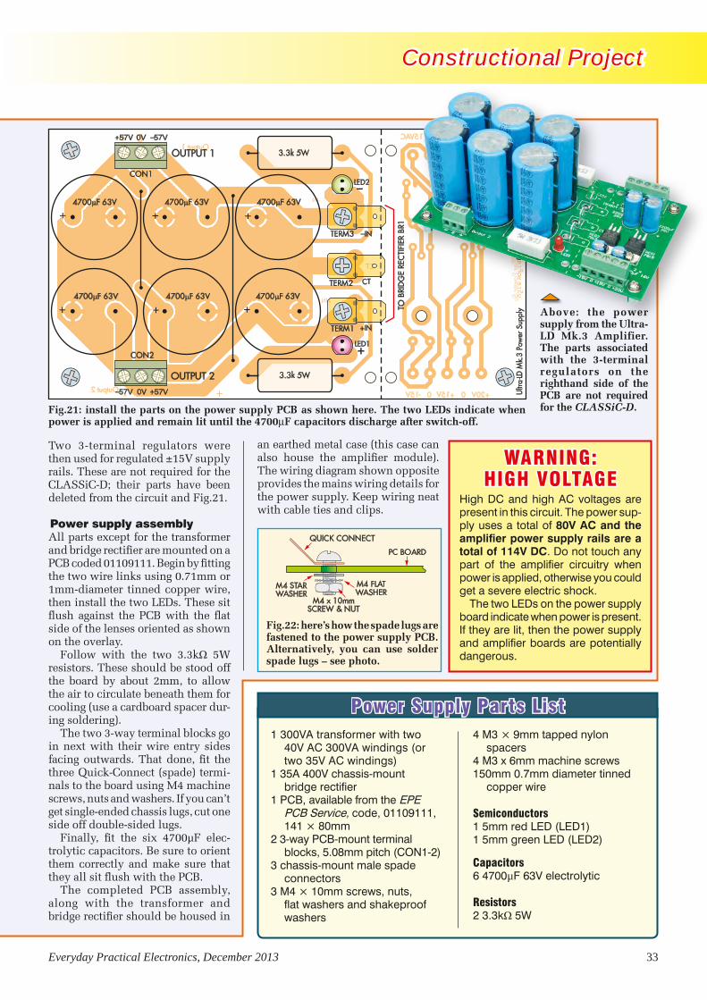
Everyday Practical Electronics, December 2013 33
Constructional Project Constructional Project
1 300VA transformer with two 40V AC 300VA windings (or two 35V AC windings)
1 35A 400V chassis-mount bridge rectifier
1 PCB, available from the EPE PCB Service, code, 01109111, 141 × 80mm
2 3-way PCB-mount terminal blocks, 5.08mm pitch (CON1-2)
3 chassis-mount male spade connectors
3 M4 × 10mm screws, nuts, flat washers and shakeproof washers
4 M3 × 9mm tapped nylon spacers
4 M3 x 6mm machine screws150mm 0.7mm diameter tinned
copper wire
Semiconductors1 5mm red LED (LED1)1 5mm green LED (LED2)
Capacitors6 4700µF 63V electrolytic
Resistors2 3.3kΩ 5W
Power Supply Parts List
Ultra-LD Mk.2 Amplifier Power Su
01109111
+
+
-
-
0Output 1
Output 2
-IN
+IN
CT
15VAC CT 15 30VAC~
-15V 0 +15V 0 +20V
4700 F 63V
4700 F 63V
4700 F 63V
4700 F 63V
4700 F 63V
4700 F 63V
CON1
CON2
TERM1
TERM2
TERM3
LED2
LED1
Ultr
a-LD
Mk.
3 Po
wer
Sup
ply
0110
9111
–
+
+
+
+
+
+
+
OUTPUT 2
OUTPUT 1
+57V 0V –57V
–57V 0V +57V
CT
+IN
–IN
3.3k 5W
3.3k 5W
TO B
RID
GE
REC
TIFI
ER B
R1
Two 3-terminal regulators were then used for regulated ±15V supply rails. These are not required for the CLASSiC-D; their parts have been deleted from the circuit and Fig.21.
Power supply assemblyAll parts except for the transformer and bridge rectifier are mounted on a PCB coded 01109111. Begin by fitting the two wire links using 0.71mm or 1mm-diameter tinned copper wire, then install the two LEDs. These sit flush against the PCB with the flat side of the lenses oriented as shown on the overlay.
Follow with the two 3.3kΩ 5W resistors. These should be stood off the board by about 2mm, to allow the air to circulate beneath them for cooling (use a card board spacer dur-ing soldering).
The two 3-way terminal blocks go in next with their wire entry sides facing outwards. That done, fit the three Quick-Connect (spade) termi-nals to the board using M4 machine screws, nuts and washers. If you can’t get single-ended chassis lugs, cut one side off double-sided lugs.
Finally, fit the six 4700µF elec-trolytic capacitors. Be sure to orient them correctly and make sure that they all sit flush with the PCB.
The completed PCB assembly, along with the transformer and bridge rectifier should be housed in
Fig.21: install the parts on the power supply PCB as shown here. The two LEDs indicate when power is applied and remain lit until the 4700mF capacitors discharge after switch-off.
Above: the power supply from the Ultra-LD Mk.3 Amplifier. The parts associated with the 3-terminal regulators on the righthand side of the PCB are not required for the CLASSiC-D.
WARNING: HIGH VOLTAGE
High DC and high AC voltages are present in this circuit. The power sup-ply uses a total of 80V AC and the amplifier power supply rails are a total of 114V DC. Do not touch any part of the amplifier circuitry when power is applied, otherwise you could get a severe electric shock.
The two LEDs on the power supply board indicate when power is present. If they are lit, then the power supply and amplifier boards are potentially dangerous.
an earthed metal case (this case can also house the amplifier module). The wiring diagram shown opposite provides the mains wiring details for the power supply. Keep wiring neat with cable ties and clips.
QUICK CONNECT
M4 x 10mmSCREW & NUT
M4 FLATWASHER
M4 STARWASHER
PC BOARD
Fig.22: here’s how the spade lugs are fastened to the power supply PCB. Alternatively, you can use solder spade lugs – see photo.
ClassD Amplifier Pt2 1212.indd 33 16/10/2013 10:25:08

34 Everyday Practical Electronics, December 2013
Constructional Project Constructional Project
It’s simply a matter of attaching these transistors to the heatsink and tightening their mounting screws, then flipping the board over and soldering the leads. That done, use a multimeter to check that the metal tab of each device is electrically iso-lated from the heatsink (you should get a high megohm or open-circuit resistance reading). Note that the heatsink is anodised, so in order for the multimeter probe to make good contact it must be touched against a bare metal area. Alternatively, if the mounting holes have been tapped, you can simply test for shorts be-tween the device tabs and the mount-ing screws.
If the meter does show a short, undo the mounting screw for that device and locate the source of the problem before re-attaching it.
Finally, the heatsink must be con-nected to the GND PC stake on the PCB. That’s done by attaching a solder lug to the heatsink at top left using an M3 × 5mm machine screw, then run-ning a short length of tinned copper wire back to the adjacent GND stake. If the hole isn’t tapped, then be sure to scrape away the anodising under the solder lug.
If necessary, this earthing arrange-ment can later be changed when the
amplifier is installed in a metal case. In that case, the heatsink should be earthed to the metal chassis itself.
Testing the amplifier moduleWith the assembly now completed, it’s time to go through the test proce-dure. Just follow these step-by-step instructions:STEP 1: install a jumper shunt across the LK3 (Protect) header, just to the right of trimpot VR1. This places the amplifier in the PROTECT mode, so that it will not start up when power is applied.STEP 2: install a jumper link on LK1, a jumper on LK2 (near the RCA sock-ets) in the NORMAL position and a jumper on LK4 to allow the PROTECT LED to light.STEP 3: monitor the resistance be-tween TP1 and GND and adjust VR1 to give a reading of 850Ω. This sets the quiescent operating frequency for the amplifier to about 500kHz.STEP 4: insert fuses F1 and F2, then connect a power supply to the CLASSiC-D module, making sure the polarity is correct. As mentioned last month, the Ultra-LD Mk.3 Power Sup-ply can be used. The circuit and the parts layout for this supply are shown in the accompanying panel.
STEP 5: switch on the power sup-ply and check that the protect LED (LED2) lights. Note that high voltages are present on the power supply and amplifier PCBs during operation. Do not handle or touch the power supply or the amplifier module with power applied, otherwise you could get a severe shock.STEP 6: check that the ±50V (or there-abouts) supply rails are correct at CON2 (note: these rails will depend on the power supply used). If these are correct, check that VAA (near ZD3) is at +5.6V (ie, measure between VAA and GND). Similarly, check that both VSS (near ZD4) and CSD are at –5.6V.STEP 7: check that VCC is around +14 to 15V (measure between VCC and COM), then check the voltage across the output terminals at CON3 (ie, the speaker terminals). This should be around 1.57V with a 50V supply, but will drop to only 6mV or less with an 8Ω or 4Ω load connected.STEP 8: check the voltage between VB and Vs. This should be above 9V, but will rise to 14V or 15V when the ampli-fier is actually running (ie, when it is no longer in PROTECT mode).
If any of the voltages in the above steps are incorrect, switch off imme-diately and check that all parts are
CHANNEL2
CHANNEL1
IN+IN-
IN+
IN-
OUT+OUT-
OUT+
OUT-
V+0V
+
+
CLASSiC-D SPEAKER PROTECTOR
01108122
LED3
CON1
CON2
47 F
Q10
ZD7
D8
10k
221M
1k
100k
RLY1* S4313
D6
D7
1k1k
IN+
IN+
IN–
IN–
OU
T–O
UT–
OU
T+O
UT+
V+0V
+
+
AK
PROTEC
T IN1
PROTEC
T IN2 R12: 4.7k 1W
STP16NE06
PROTECT
CLASSiC-D SPEAKER PROTECTOR 01108122
C 2012
CH
AN
NEL
2C
HA
NN
EL1
4004
4148
4148
15V
OPT
O1
4N28
OPT
O1
4N28
OPT
O2
4N28
OPT
O2
4N28
_
+
COM NO NC
CO
IL
R11: 820 5W
V+ 50V 35V 25VR11R12
820 5W 330 1W 22 0.5W4.7k 1W 2.7k 0.5W 1.5k 0.5W
* RLY1 HAS A 24V/650 COIL
Fig.23: install the parts on the Loudspeaker Protector PCB as shown here. Note that resistors R11 and R12 have to be selected to suit the power supply voltage, as shown in the accompanying table. The 10-way screw terminal block is made by dovetailing five 2-way terminal blocks together before soldering them to the PCB.
CHANNEL2
CHANNEL1
IN+IN-
IN+
IN-
OUT+OUT-
OUT+
OUT-
V+0V
+
+
CLASSiC-D SPEAKER PROTECTOR
01108122
LED3
CON1
CON2
47 F
Q10
ZD7
D8
10k
221M
1k
100k
RLY1* S4313
D6
D7
1k1k
IN+
IN+
IN–
IN–
OU
T–O
UT–
OU
T+O
UT+
V+0V
+
+
AK
PROTEC
T IN1
PROTEC
T IN2 R12: 4.7k 1W
STP16NE06
PROTECT
CLASSiC-D SPEAKER PROTECTOR 01108122
C 2012
CH
AN
NEL
2C
HA
NN
EL1
4004
4148
4148
15V
OPT
O1
4N28
OPT
O1
4N28
OPT
O2
4N28
OPT
O2
4N28
_
+
COM NO NC
CO
IL
R11: 820 5W
V+ 50V 35V 25VR11R12
820 5W 330 1W 22 0.5W4.7k 1W 2.7k 0.5W 1.5k 0.5W
* RLY1 HAS A 24V/650 COIL
CHANNEL2
CHANNEL1
IN+IN-
IN+
IN-
OUT+OUT-
OUT+
OUT-
V+0V
+
+
CLASSiC-D SPEAKER PROTECTOR
01108122
LED3
CON1
CON2
47 F
Q10
ZD7
D8
10k
221M
1k
100k
RLY1* S4313
D6
D7
1k1k
IN+
IN+
IN–
IN–
OU
T–O
UT–
OU
T+O
UT+
V+0V
+
+
AK
PROTEC
T IN1
PROTEC
T IN2 R12: 4.7k 1W
STP16NE06
PROTECT
CLASSiC-D SPEAKER PROTECTOR 01108122
C 2012
CH
AN
NEL
2C
HA
NN
EL1
4004
4148
4148
15V
OPT
O1
4N28
OPT
O1
4N28
OPT
O2
4N28
OPT
O2
4N28
_
+
COM NO NC
CO
IL
R11: 820 5W
V+ 50V 35V 25VR11R12
820 5W 330 1W 22 0.5W4.7k 1W 2.7k 0.5W 1.5k 0.5W
* RLY1 HAS A 24V/650 COIL CHAN
NEL2
CHANN
EL1
IN+
IN-
IN+
IN-
OUT
+OUT
-
OUT
+
OUT
-
V+0V
+
+ CLASSiC-D SP
EAKER
PROTEC
TOR
01108122
LED3
CON1
CON2
47F
Q10
ZD7
D8
10k
221M
1k
100k
RLY1*S4313
D6
D7
1k
1k
IN+
IN+
IN–
IN–
OUT
–
OUT
– OUT
+
OUT
+
V+0V
+
+
AK
PROTECT IN
1
PROTECT IN
2
R12: 4.7k 1W
STP16NE06
PROTECT
CLASSiC-D SPEAKER PROTECTOR
01108122
C 2012
CHANN
EL2
CHANN
EL1
4004
41484148
15V
OPT
O1
4N28OPT
O1
4N28
OPT
O2
4N28OPT
O2
4N28
_
+
COMNO
NC
COIL
R11: 8205W
V+
50V
35V
25V
R11R12 8205W
3301W
220.5W
4.7k 1W
2.7k 0.5W1.5k 0.5W
*RLY1 HAS A 24V/
650COIL
CLASSiC-D AMPLIFIER 01108121
CON3CON2
+
LK1
TP1
1
+
CLASSiC-D AMPLIFIER 2012C
LK2
+
+50V
–50V
0V
4004
4004
MU
R12
0
MU
R12
0
15V
15V
68V
39V
5.6V
5.6V
4148
4004
CHANNEL2
CHANNEL1
IN+IN-
IN+
IN-
OUT+OUT-
OUT+
OUT-
V+0V
+
+
CLASSiC-D SPEAKER PROTECTOR
01108122
CON1
CON2
IN+
IN+
IN–
IN–
OU
T–O
UT–
OU
T+O
UT+
V+0V
+
+
PROTEC
T IN1
PROTEC
T IN2
PROTECT
CLASSiC-D SPEAKER PROTECTOR 01108122
C 2012
CH
AN
NEL
2C
HA
NN
EL1
4004
4148
4148
15V
_
+
COM NO NC
CO
IL
SPEAKER4 OR 8 +
–
LK4
INPUT +50V0V
CLASSiC-D AMPLI
FIER
01108121
CON3
CON2
+
LK1
TP1
1
+
CLASSiC-D AMPLIFIER
2012
C
LK2
+
+50V
–50V
0V
4004
4004
MUR
120
MUR
120
15V
15V
68V
39V
5.6V
5.6V
4148
4004
CHANN
EL2
CHANN
EL1
IN+
IN-
IN+
IN-
OUT
+OUT
-
OUT
+
OUT
-
V+0V
+
+ CLASSiC-D SP
EAKER
PROTEC
TOR
01108122
CON1
CON2
IN+
IN+
IN–
IN–
OUT
–
OUT
– OUT
+
OUT
+
V+0V
+
+
PROTECT IN
1
PROTECT IN
2
PROTECT
CLASSiC-D SPEAKER PROTECTOR
01108122
C 2012
CHANN
EL2
CHANN
EL1
4004
41484148
15V
_
+
COMNO
NC
COIL
SPEAKER4
OR 8
+–
LK4
INPUT
+50V
0V
ClassD Amplifier Pt2 1212.indd 34 16/10/2013 10:25:35


Everyday Practical Electronics, December 2013 37
Constructional Project Constructional Project
CLASSiC-D AMPLIFIER 01108121
CON3CON2
+
LK1
TP1
1
+
CLASSiC-D AMPLIFIER 2012C
LK2
+
+50V
–50V
0V
4004
4004
MU
R12
0
MU
R12
0
15V
15V
68V
39V
5.6V
5.6V
4148
4004
CLASSiC-D AMPLIFIER 01108121
CON3CON2
+
LK1
TP1
1
+
CLASSiC-D AMPLIFIER 2012C
LK2
+
+50V
–50V
0V
4004
4004
MU
R12
0
MU
R12
0
15V
15V
68V
39V
5.6V
5.6V
4148
4004
CHANNEL2
CHANNEL1
IN+IN-
IN+
IN-
OUT+OUT-
OUT+
OUT-
V+0V
+
+
CLASSiC-D SPEAKER PROTECTOR
01108122
CON1
CON2
IN+
IN+
IN–
IN–
OU
T–O
UT–
OU
T+O
UT+
V+0V
+
+
PROTEC
T IN1
PROTEC
T IN2
PROTECTED
CLASSiC-D SPEAKER PROTECTOR 01108122
C 2012
CH
AN
NEL
2C
HA
NN
EL1
4004
4148
4148
15V
_
+
COM NO NC
CO
IL
8SPEAKER
+–
LK4 LK4
SIGNALINPUT
LK2 IN NORMALPOSITION
LK2 IN INVERTPOSITION
RCA-TO-RCASHIELDED LEAD
AMPLIFIER 1 AMPLIFIER 2
+50V0V
Where to buy kits and parts
Both Jaycar and Altronics have full kits available for the CLASSiC-D amplifier module and its Loudspeaker Protector. The details are as follows:
JaycarCLASSiC-D Amplifier Kit (includes pre-mounted SMD IC) – Cat. KC-5514CLASSiC-D Speaker Protector Kit – Cat. KC-5515
AltronicsCLASSiC-D Amplifier Kit – Cat. K 5181CLASSiC-D Speaker Protector Kit – Cat. K 5182Power Supply Kit (Ultra-LD Mk.3 Supply) – Cat. K 5168
PCBs: PCBs for the CLASSiC-D Amplifier, Loudspeaker Protector and the Ultra-LD Mk.3 Power Supply can be purchased separately from EPE.
In addition, Amplifier 2 must be set to INVERT mode using LK2, while Amplifier 1 operates with LK2 in the NORMAL position.
The completed modules can be mounted in a metal case, along with the power supply. Make sure the case is securely earthed and be sure to use an IEC mains input connector with an integral M205 5A fuse.
Fig.26: the bridge mode configuration uses just one relay channel on the Loudspeaker Protector. An RCA-to-RCA shielded lead is connected between the signal inputs of the two amplifiers, while LK2 is set to NORMAL on one amplifier and to INVERT on the other. Note that the loudspeaker must be an 8Ω (or higher) type for bridged operation.
Reproduced by arrangement with SILICON CHIP
magazine 2013.www.siliconchip.com.au
CLASSiC-D AMPLIFIER 01108121
CON3CON2
+
LK1
TP1
1
+
CLASSiC-D AMPLIFIER 2012C
LK2
+
+50V
–50V
0V
4004
4004
MU
R12
0
MU
R12
0
15V
15V
68V
39V
5.6V
5.6V
4148
4004
CHANNEL2
CHANNEL1
IN+IN-
IN+
IN-
OUT+OUT-
OUT+
OUT-
V+0V
+
+
CLASSiC-D SPEAKER PROTECTOR
01108122
CON1
CON2
IN+
IN+
IN–
IN–
OU
T–O
UT–
OU
T+O
UT+
V+0V
+
+
PROTEC
T IN1
PROTEC
T IN2
PROTECT
CLASSiC-D SPEAKER PROTECTOR 01108122
C 2012
CH
AN
NEL
2C
HA
NN
EL1
4004
4148
4148
15V
_
+
COM NO NC
CO
IL
SPEAKER4 OR 8 +
–
LK4
INPUT +50V0V
CHANNEL2
CHANNEL1
IN+IN-
IN+
IN-
OUT+OUT-
OUT+
OUT-
V+0V
+
+
CLASSiC-D SPEAKER PROTECTOR
01108122
LED3
CON1
CON2
47 F
Q10
ZD7
D8
10k
221M
1k
100k
RLY1* S4313
D6
D7
1k1k
IN+
IN+
IN–
IN–
OU
T–O
UT–
OU
T+O
UT+
V+0V
+
+
AK
PROTEC
T IN1
PROTEC
T IN2 R12: 4.7k 1W
STP16NE06
PROTECT
CLASSiC-D SPEAKER PROTECTOR 01108122
C 2012
CH
AN
NEL
2C
HA
NN
EL1
4004
4148
4148
15V
OPT
O1
4N28
OPT
O1
4N28
OPT
O2
4N28
OPT
O2
4N28
_
+
COM NO NC
CO
IL
R11: 820 5W
V+ 50V 35V 25VR11R12
820 5W 330 1W 22 0.5W4.7k 1W 2.7k 0.5W 1.5k 0.5W
* RLY1 HAS A 24V/650 COIL
CHANNEL2
CHANNEL1
IN+
IN-
IN+
IN-
OUT+OUT-
OUT+
OUT-
V+0V
+
+
CLASS
iC-D
SPEA
KER P
ROTE
CTOR
0110
8122
LED3CON1
CON2
47F
Q10
ZD7 D8
10k
221M
1k
100k
RLY1*S4313
D6D7
1k
1k
IN+
IN+
IN–
IN–
OUT–
OUT–OUT+
OUT+
V+0V
+
+
AK
PROTECT IN1
PROTECT IN2
R12: 4.7k 1W
STP16NE06PROTECT
CLASSiC-D SPEAKER PROTECTOR
01108122
C 2012 CHANNEL2
CHANNEL1
400441484148
15V
OPTO1
4N28OPT
O1
4N28
OPTO2
4N28OPT
O2
4N28
_
+
COM
NONC
COIL
R11: 8205W
V+
50V
35V
25V
R11R12
8205W
3301W
220.5W
4.7k 1W
2.7k 0.5W1.5k 0.5W
*RLY1 HAS A 24V/
650COIL
CLASSiC-D AMPLIFIER 01108121
CON3CON2
+
LK1
TP1
1
+
CLASSiC-D AMPLIFIER 2012C
LK2
+
+50V
–50V
0V
4004
4004
MU
R12
0
MU
R12
0
15V
15V
68V
39V
5.6V
5.6V
4148
4004
CHANNEL2
CHANNEL1
IN+IN-
IN+
IN-
OUT+OUT-
OUT+
OUT-
V+0V
+
+
CLASSiC-D SPEAKER PROTECTOR
01108122
CON1
CON2
IN+
IN+
IN–
IN–
OU
T–O
UT–
OU
T+O
UT+
V+0V
+
+
PROTEC
T IN1
PROTEC
T IN2
PROTECT
CLASSiC-D SPEAKER PROTECTOR 01108122
C 2012
CH
AN
NEL
2C
HA
NN
EL1
4004
4148
4148
15V
_
+
COM NO NC
CO
IL
SPEAKER4 OR 8 +
–
LK4
INPUT +50V0V
CHANNEL2
CHANNEL1
IN+IN-
IN+
IN-
OUT+OUT-
OUT+
OUT-
V+0V
+
+
CLASSiC-D SPEAKER PROTECTOR
01108122
LED3
CON1
CON2
47 F
Q10
ZD7
D8
10k
221M
1k
100k
RLY1* S4313
D6
D7
1k1k
IN+
IN+
IN–
IN–
OU
T–O
UT–
OU
T+O
UT+
V+0V
+
+
AK
PROTEC
T IN1
PROTEC
T IN2 R12: 4.7k 1W
STP16NE06
PROTECT
CLASSiC-D SPEAKER PROTECTOR 01108122
C 2012
CH
AN
NEL
2C
HA
NN
EL1
4004
4148
4148
15V
OPT
O1
4N28
OPT
O1
4N28
OPT
O2
4N28
OPT
O2
4N28
_
+
COM NO NCC
OIL
R11: 820 5W
V+ 50V 35V 25VR11R12
820 5W 330 1W 22 0.5W4.7k 1W 2.7k 0.5W 1.5k 0.5W
* RLY1 HAS A 24V/650 COIL
CHANNEL2
CHANNEL1
IN+IN-
IN+
IN-
OUT+OUT-
OUT+
OUT-
V+0V
+
+
CLASSiC-D SPEAKER PROTECTOR
01108122LED3
CON1
CON2
47 F Q10
ZD7
D8
10k
22
1M1k
100k
RLY1* S4313D6
D71k
1k
IN+
IN+
IN–
IN–
OU
T–
OU
T–O
UT+
OU
T+
V+0V
+
+
AK
PROTEC
T IN1
PROTEC
T IN2
R12: 4.7k 1W
STP16NE06
PROTECT
CLASSiC-D SPEAKER PROTECTOR
01108122
C 2012
CH
AN
NEL
2
CH
AN
NEL
1
4004
4148
414815
V
OPT
O1
4N28
OPT
O1
4N28
OPT
O2
4N28
OPT
O2
4N28
_
+
COM NO NC
CO
IL
R11: 820 5W
V+50V
35V25V
R11R12
820 5W330 1W
22 0.5W4.7k 1W 2.7k 0.5W 1.5k 0.5W
* RLY1 HAS A 24V/650 COIL
CHANNEL2
CHANNEL1
IN+IN-
IN+
IN-
OUT+OUT-
OUT+
OUT-
V+0V
+
+
CLASSiC-D SPEAKER PROTECTOR
01108122
LED3
CON1
CON2
47 F
Q10
ZD7
D8
10k
221M
1k
100k
RLY1* S4313
D6
D7
1k1k
IN+
IN+
IN–
IN–
OU
T–O
UT–
OU
T+O
UT+
V+0V
+
+
AK
PROTEC
T IN1
PROTEC
T IN2 R12: 4.7k 1W
STP16NE06
PROTECT
CLASSiC-D SPEAKER PROTECTOR 01108122
C 2012
CH
AN
NEL
2C
HA
NN
EL1
4004
4148
4148
15V
OPT
O1
4N28
OPT
O1
4N28
OPT
O2
4N28
OPT
O2
4N28
_
+
COM NO NC
CO
IL
R11: 820 5W
V+ 50V 35V 25VR11R12
820 5W 330 1W 22 0.5W4.7k 1W 2.7k 0.5W 1.5k 0.5W
* RLY1 HAS A 24V/650 COIL
ClassD Amplifier Pt2 1212.indd 37 16/10/2013 10:26:29

38 Everyday Practical Electronics, December 2013
IT IS BACK...
EVERYDAY PRACTICAL ELECTRONICS IS NOW
AVAILABLE IN PDF FORMAT AGAIN
REQUIREMENTS:
YOU NEED TO BE RUNNING A WINDOWS PCUSING ADOBE ACROBAT READER
GO TO
www.epemag.comTO ORDER
WIN A MICROCHIP
MPLAB STARTER KIT FOR DIGITAL
POWER
Teach-In 2014 Raspberry Pi – Part 2LED MusicoLour – Part 2
sPEctacuLar Light anD Music show
plus: Net work, readout, CirCuit surgery,
teChNo talk & praCtiCally speakiNg
cLassic-D aMPLifiEr
high efficiency, high power
Low distortion, low noise
Bridging option for 8Ω loads
speaker protection module
EPE’s comprehensive guide to Raspberry Pi
NOV 2013 £4.40
NOV 13 Cover.indd 1
18/09/2013 18:33:28
PDF EPE Sub Page.indd 38 16/10/2013 10:27:03

Everyday Practical Electronics, December 2013 39
AGILENT E4407B Spectrum Analyser – 100HZ-26.5GHZ £6,500AGILENT E4402B Spectrum Analyser – 100HZ-3GHZ £3,500HP 3325A Synthesised Function Generator £250HP 3561A Dynamic Signal Analyser £800HP 3581A Wave Analyser – 15HZ-50KHZ £250HP 3585A Spectrum Analyser – 20HZ-40MHZ £995HP 53131A Universal Counter – 3GHZ £600HP 5361B Pulse/Microwave Counter – 26.5GHZ £1,500HP 54502A Digitising Scope 2ch – 400MHZ 400MS/S £295HP 54600B Oscilloscope – 100MHZ 20MS/S from £195HP 54615B Oscilloscope 2ch – 500MHZ 1GS/S £800HP 6030A PSU 0-200V 0-17A – 1000W £895HP 6032A PSU 0-60V 0-50A – 1000W £750HP 6622A PSU 0-20V 4A twice or 0-50v2a twice £350HP 6624A PSU 4 Outputs £350HP 6632B PSU 0-20V 0-5A £195HP 6644A PSU 0-60V 3.5A £400HP 6654A PSU 0-60V 0-9A £500HP 8341A Synthesised Sweep Generator – 10MHZ-20GHZ £2,000HP 8350B with 83592a Generator – 10MHZ-20GHZ £600HP 83731A Synthesised Signal Generator – 1-20GHZ £2,500HP 8484A Power Sensor – 0.01-18GHZ 3nW-10uW £125HP 8560A Spectrum Analyser synthesised – 50HZ -2.9GHZ £2,100HP 8560E Spectrum Analyser synthesised – 30HZ--2.9GHZ £2,500HP 8563A Spectrum Analyser synthesised – 9KHZ-22GHZ £2,995HP 8566A Spectrum Analyser – 100HZ-22GHZ £1,600HP 8662A RF Generator – 10KHZ-1280MHZ £1,000HP 8672A Signal Generator – 2-18GHZ £500HP 8673B Synthesised Signal Generator – 2-26GHZ £1,000HP 8970B Noise Figure Meter £995HP 33120A Function Generator – 100 microHZ-15MHZ £395MARCONI 2022E Synthesised AM/FM Sig Generator – 10KHZ-1.01GHZ £395MARCONI 2024 Synthesised Signal Generator – 9KHZ-2.4GHZ from £800MARCONI 2030 Synthesised Signal Generator – 10KHZ-1.35GHZ £950MARCONI 2305 Modulation Meter £250MARCONI 2440 Counter20GHZ £395MARCONI 2945 Comms Test Set various options £3,000
MARCONI 2955 Radio Comms Test Set £595MARCONI 2955A Radio Comms Test Set £725MARCONI 2955B Radio Comms Test Set £850MARCONI 6200 Microwave Test Set £2,600MARCONI 6200A Microwave Test Set – 10MHZ-20GHZ £3,000MARCONI 6200B Microwave Test Set £3,500IFR 6204B Microwave Test Set – 40GHZ £12,500MARCONI 6210 Reflection Analyser for 6200Test Sets £1,500MARCONI 6960B with 6910 Power Meter £295MARCONI TF2167 RF Amplifier – 50KHZ-80MHZ 10W £125TEKTRONIX TDS3012 Oscilloscope – 2ch 100MHZ 1.25GS/S £1,100TEKTRONIX TDS540 Oscilloscope – 4ch 500MHZ 1GS/S £600TEKTRONIX TDS620B Oscilloscope – 2+2ch 500MHZ 2.5GHZ £600TEKTRONIX TDS684A Oscilloscope – 4ch 1GHZ 5GS/S £2,000TEKTRONIX 2430A Oscilloscope Dual Trace – 150MHZ 100MS/S £350TEKTRONIX 2465B Oscilloscope – 4ch 400MHZ £600TEKTRONIX TFP2A Optical TDR £350R&S APN62 Synthesised Function Generator – 1HZ-260KHZ £225R&S DPSP RF Step Attenuator – 139db £400R&S SME Signal Generator – 5KHZ-1.5GHZ £500R&S SMK Sweep Signal Generator – 10MHZ-140MHZ £175R&S SMR40 Signal Generator – 10MHZ-40GHZ with options £13,000R&S SMT06 Signal Generator – 5KHZ-6GHZ £4,000R&S SW0B5 Polyscope – 0.1-1300MHZ £250CIRRUS CL254 Sound Level Meter with Calibrator £60FARNELL AP60/50 PSU 0-60V 0-50A 1KW Switch Mode £250FARNELL H60/50 PSU 0-60V 0-50A £500FARNELL B30/10 PSU 30V 10A Variable No meters £45FARNELL B30/20 PSU 30V 20A Variable No meters £75FARNELL XA35/2T PSU 0-35V 0-2A twice Digital £75FARNELL LF1 Sine/sq Oscillator – 10HZ-1MHZ £45
FARNELL XA35/2T PSU 0-35V 0-2A twice Digital £75FARNELL LF1 Sine/sq Oscillator 10HZ-1MHZ £45RACAL 1792 Receiver £250RACAL 1991 Counter/Timer 160MHZ 9 digit £150RACAL 2101 Counter20GHZ LED £350
SPECIAL OFFERS for full sales listcheck our website
STEWART OF READING17A King Street, Mortimer, Near Reading, RG7 3RSTelephone: 0118 933 1111• Fax: 0118 933 2375
9am – 5pm, Monday – FridayPlease check availability before ordering or CALLING IN
Used Equipment – GUARANTEEDAll items supplied as tested in our Lab
Prices plus Carriage and VAT
Page 39.indd 39 16/10/2013 10:27:50


of a program after first importing any required library modules. Once defined, UDFs can be called as many times as they are needed. UDFs also support the ability to pass one or more variables in from the main program and have values returned to the main program for subsequent processing. Let’s look at a very simple UDF that does nothing except print a message. First, UDFs are defined in the following way:
# Warn user that he/she is about to quitdef warn(): print(‘You have selected Quit’) print(‘Are you sure?’)
To make use of the UDF you would simply include the following line later in your program:
warn()
When the line of code is executed (and the UDF has been called) the following lines will appear in the console:
You have selected QuitAre you sure?
Passing parametersTo pass one or more values into a UDF we place variables inside the parenthesis that follows the name of the UDF, as shown in the next example:
# Function to convert Celsius to Fahrenheitdef c_to_f(x): return(9/5 * x + 32)
Notice how the value returned by the UDF (in this case it is the Fahrenheit equivalent of a Celsius temperature) appears in the return statement. To make practical use of this UDF we would need something along the following lines:
# Get a temperature and convert it!cS = input(‘Enter a temperature in deg.C: ‘)c = float(cS)print(cS + ‘ deg.C is equivalent to ‘ + str(c_to_f(c)) + ‘ deg.F’)
Note that the Celsius value entered at the keyboard is a string (cS) and this needs to be converted to a floating point value (c) that can be passed into the UDF. The returned value then needs to be converted from a floating point value to a string (using str()) before it can be printed. If you enter the program into the IDLE editor and then run it you will see something like the following:
Enter a temperature in deg.C: +120+120 deg.C is equivalent to 248.0 deg.F
Now, here’s an example of passing two values into a UDF and returning values that are subsequently used in a main program:
# Function to determine time constant of a C-R circuitdef cr_time(x, y): return(x * y)
# Function to determine the cut-off frequency of a C-R filterdef cr_freq(x, y): return(0.159 / (x * y))
# Get values of C and RcS = input(‘Enter value of capacitance in uF: ‘)c = float(cS)rS = input(‘Enter value of resistance in Mohm: ‘)r = float(rS)
# Print the resultsprint(‘Time constant is %.3f seconds’ % cr_time(c, r))print(‘Cut-off frequency is %.3f Hz’ % cr_freq(c, r))
The typical output from this program is shown below. Note that the print library function can incorporate formatting (in this case the %.3f displays the values returned by the two UDFs to three places after each decimal point).
Enter value of capacitance in uF: 0.22Enter value of resistance in Mohm: 0.15Time constant is 0.033 secondsCut-off frequency is 4.818 Hz
Dealing with non-numeric inputUnfortunately, neither of the two examples that we’ve just described can cope with an input that is anything but a number. If you run either of the programs and enter non-numeric characters (other than + and –) you will find that the program terminates in a rather ugly fashion and it would be good practice to warn the user when he or she enters a value that the program can’t use. To do this, we can add a couple of lines to the program that will allow us to exit to a more meaningful message, as shown in the following example. Note that we need to import the sys library in order to display a message when the program exits due to an error. In a later Teach-In we will deal with the tricky question of input validation, but for the moment this is at least an improvement on what we had before:
Everyday Practical Electronics, December 2013 41
Fig.3.1. Simplified block schematic of eight-channel output driver
We mentioned this last month, but it’s worth repeating: at the end any program, and before the program makes an exit back to the operating system, it is good practice to clean up by setting the mode of all of the I/O channels to what you’ve decided is their default input state. To do this you can add a single line of code at the end of your program:
GPIO.cleanup()
Note that, in order to save space, we have not included this line in any of the sample fragments of code shown in this issue of Teach-In, but we do advise you to include it in your own code.
Don’t forget to clean up!
TI-3 MP.indd 41 16/10/2013 10:28:25

Pi Project
Last month, in Pi Project, we explained the electrical characteristics of the Raspberry Pi’s general purpose input/output (GPIO) port. We also introduced the techniques for configuring the port for simple I/O operations, such as flashing an LED or sounding a buzzer. This month, we shall be further developing that theme by describing a simple eight-channel output driver that can be used to interface a Raspberry Pi to components and devices that make relatively high current and/or high voltage demands, such as relays, motors, actuators and sounders.
Eight-channel output driverThe simplified block schematic of our eight-channel output driver showing loads and power supply is shown in Fig.3.1.The circuit is based on a single ULN2803 integrated circuit. This handy device is an octal (eight-channel) high voltage/high current driver array. The pin connections for a ULN2803 are shown in Fig.3.2. Note that the common ground connection is taken to pin-9, while the positive supply is taken to pin-10. The device is capable of handling load currents of up to 500mA and voltages up to 50V. The input of the ULN2803 is compatible with standard 5V TTL and CMOS devices, but it will operate quite happily with the 3.3V logic available from the Raspberry Pi’s GPIO output pins.
The simplified internal circuitry of each of the eight channels of a ULN2803 is shown in Fig.3.3. TR1 and
TR2 are connected as a Darlington pair which ensures very high current gain (roughly equal to the product of the two individual current gains for TR1 and TR2). D1 provides input reverse polarity protection, and D2 and D3 protect the device from high voltages that might appear at the collector of TR1 and TR2 when switching an inductive load such as a relay, actuator or motor.
The complete circuit o f the 8 - channe l output driver is shown in Fig.3.4. The eight input diodes (D1 to D8) provide reverse voltage protect ion for the Raspberry Pi’s GPIO outputs. The eight outputs from IC1 are taken to an 18-way connector (P2). One set of pins on this connector is connected to the common positive supply (this will typically be +12V derived from a suitably rated external power supply). The pin connections for P2 are shown in Fig.3.5, and the individual pin assignments are given in Table 1.
The Humble Pi prototyping boardWe built our eight-channel output driver using a ‘Humble Pi’ prototyping board (see Fig.3.6). This handy board can be fitted with the 26-way connector (supplied with the Humble Pi) so that the board sits piggy-back style immediately above the Raspberry Pi. The result is an extremely neat and compact layout. The wiring diagram for the eight-channel output driver is shown in Fig.3.7.
Power suppliesThe eight-channel output driver should be tested before connecting it to any external loads. In order to test the prototype we decided to make use of the simple on-board voltage regulator kit that can be supplied as an optional accessory for the Humble Pi (shown in Fig.3.6). This kit consists of a low-dropout voltage regulator (LD33V, LD50V, or equivalent), two capacitors, and a standard DC power connector. Note
42 Everyday Practical Electronics, December 2013
that when ordering a power supply kit for this particular application it would be worth specifying the use of a 5V regulator. The four additional power supply components can be quickly and
Table 1: Pin assignments for output connector P2
Fig.3.2. Pin connections for a ULN2803 (viewed from the top)
Fig.3.3. Simplified internal circuitry of one channel of the ULN2803
Fig.3.4. Complete circuit of eight-channel output driver
GPIO pin number
Humble Pi GP number
Output pin identifier
11 GP0 OP1
12 GP1 OP2
13 GP2 OP315 GP3 OP416 GP4 OP518 GP5 OP622 GP6 OP77 GP7 OP8
Fig.3.5. Pin connections for output connector P2
import sys
# Function to convert Celsius to Fahrenheitdef c_to_f(x): return(9/5 * x + 32)
# Get a temperature and convert it!cS = input(‘Enter a temperature in deg.C: ‘)
try: c = float(cS)except ValueError: sys.exit(‘You must enter a number!’) print(cS + ‘ deg.C is equivalent to ‘ + str(c_to_f(c)) + ‘ deg.F’)
TI-3 MP.indd 42 16/10/2013 10:28:35

easily fitted to the Humble Pi prototype board (see Fig.3.7 and Fig.3.8).
The link on the board (LK1) is left in place when testing with the on-board 5V supply (or when only 5V is required for the loads) but is removed when a higher voltage external supply is connected. After testing, the link can be removed and the external supply (eg, 12V or 24V) can then be connected to the two
gain root privileges, as explained in the boxed feature on the next page).
Prior to connecting real loads to the eight-channel output driver, testing can easily be carried out by simulating a load using an LED connected in series with a 270Ω current-limiting resistor, as shown in Fig.3.10. This can be connected to each of the outputs on P2 in turn before using a few lines of code to turn the respective channel on and off. The GPIO will need to be configured properly before you do this (see Home Baking).
Home Baking
In this month’s Home Baking we will be looking at how the GPIO library module can provide you with easy access to the features of the GPIO port from within your Python code. In order to help you get your eight-channel output driver up and running quickly, all of the examples that we’ve provided relate to the Humble Pi prototyping board.
Initialising the GPIOAs mentioned last month, the GPIO library module provides easy access to the features of the GPIO port from within your Python code. However, before the library module can be used it needs to be imported into your code using a statement of the form:
import RPi.GPIO as GPIO
At this point, it is worth reminding you that if you don’t have sufficient privileges the library import will fail and a run time error will be generated when this line of code is encountered during run time. To overcome this problem you need to execute your Python script as a ‘superuser’, but you can set this privilege level by simply using sudo before the
Fig.3.8. Finished prototype of the eight-channel output driver under test (note that the Humble Pi board fits neatly over the top of the Raspberry Pi)
Fig.3.9. Pin connections for standard and low-dropout voltage regulators
Fig.3.10. The simple LED test load
pins marked TP1 (+V) and TP2 (0V). Finally, don’t be tempted to fit a conventional three-terminal regulator (eg, 7805 or 7812) to the Humble Pi board because these chips have different pin connections, as shown in Fig.3.9
Testing the interfaceWhen the time comes to test the eight-channel output driver you will need to enter your code (see Home Baking) using an editor (or an IDE such as IDLE)
before saving it to the folder in which you are currently storing your Python files (we created a folder called Work_files on the desktop for storing our files, but you can save them in any convenient location). To test the code you can then start LXTerminal (or an equivalent terminal utility) and enter the appropriate command (using sudo to
Fig.3.6. The Humble Pi prototyping board and optional power supply kit
Fig.3.7. Component layout for the eight-channel output driver
Everyday Practical Electronics, December 2013 43
TI-3 MP.indd 43 16/10/2013 10:28:52

script name. For example, if your script has the name control.py you would execute it using the command:
sudo control.py
Next we need to decide which mode of operation to use with the GPIO.setmode command. We have a choice of two commands:
GPIO.setmode(GPIO.BOARD)
This allows us to use the Raspberri Pi’s own board numbering scheme while:
GPIO.setmode(GPIO.BCM)
allows us to use the numbering scheme adopted by the Broadcom chip.
Configuring the GPIO for the Humble PiThe convention adopted by the Humble Pi breadboarding system follows the board numbering scheme – so, in this particular application, we will be using the GPIO.BOARD option. Here’s a block of code that can be used to configure the GPIO:
# Configure the GPIOGPIO.setmode(GPIO.BOARD)GPIO.setup(11, GPIO.OUT) # GP0/OP1GPIO.setup(12, GPIO.OUT) # GP1/OP2GPIO.setup(13, GPIO.OUT) # GP2/OP3GPIO.setup(15, GPIO.OUT) # GP3/OP4GPIO.setup(16, GPIO.OUT) # GP4/OP5GPIO.setup(18, GPIO.OUT) # GP5/OP6GPIO.setup(22, GPIO.OUT) # GP6/OP7GPIO.setup(7, GPIO.OUT) # GP7/OP8
Next (for safety reasons) we need to ensure that all of the output lines are initially turned off. This can be done with the following block of code:
# Initialise all lines to the OFF stateGPIO.output(11, False)GPIO.output(12, False)GPIO.output(13, False)GPIO.output(15, False)GPIO.output(16, False)GPIO.output(18, False)GPIO.output(22, False)GPIO.output(7, False)
Switching the outputs on and offSwitching the output lines is easy; for example, to turn OP2 on we use this code:
# Turn OP2 onGPIO.output(12, True)
While to turn OP2 off we use:
# Turn OP2 offGPIO.output(12, False)
Notice that we’ve added comments to the code that will help us understand what the program does when the time comes to maintain or modify it.
Now for a complete example – let’s assume that we have a light connected to OP2 and a camera connected to OP3. Let’s also assume that we need to put the light on two seconds before the camera is to be operated and that the two signals must remain held on for a further two seconds before they are both turned off for an additional ten seconds, after which the entire 14-second cycle should be repeated indefinitely. We will need to import two libraries in this application; the GPIO library and the time library, as shown at the beginning of the sample code listed below.
A neat way to operate the lamp and camera is to make use of user-defined function UDFs that we described earlier in Python Quickstart. In the case of the lamp, the function that we will call to switch the light on is as follows:
def light_on(): GPIO.output(12, True)
While to switch it off we will need this function:
def light_off(): GPIO.output(12, False)
44 Everyday Practical Electronics, December 2013
Under the Debian (Linux) operating system it is important to be aware that you must have root (super user) privileges in order to execute a Python program. You can do this by specifying sudo along with the Python filename in the command line that you enter directly from within the terminal (eg, LXTerminal) program. Note that unless you have previously set the path to your Python source code, you will need to specify the full path to your file. For example, let’s assume that you have created a Python module called oc_driver and saved it with the py extension in a folder called Work_files on your desktop. In order to run the program you could use the following (rather cumbersome) command line based on the full path to your file:
sudo python /home/pi/Desktop/Work_files/oc_driver.py
This works, but it is clearly rather longwinded, so let’s look at an easier way of executing Python code from a particular directory. Assuming that you are logged in as the default user (pi) with the default password (raspberry) you could abbreviate the command as follows:
sudo python Desktop/Work_files/oc_driver.py
To make things even easier you could change your working directory by making use of Debian’s cd command, as follows:
cd Desktopcd Work_files
or by just using a single command line:
cd Desktop/Work_files
Then, to start Python and execute your program, simply enter the following command line:
sudo python oc_driver.py.
To go back to your home directory you can just type cd with no arguments or to move back to the root directory you can use:
cd /
To just move up one level (ie, back to the parent directory) you can use:
cd ..
If you wish to know which directory you’ve arrived at you can use the ls command by just typing:
ls
to list the files and folders in the current directory.’
Running Pythonprograms as root
TI-3 MP.indd 44 16/10/2013 10:28:52

the value of the switch parameter (either True or False). Thus the function that we call in order to operate the light might look like this:
def light(switch): if switch: GPIO.output(12, True) else: GPIO.output(12, False)
The code that we need to turn the light on would then be:
light(True)
While to turn if off we would need to use:
light(False)
Our final example shows how this works:
import RPi.GPIO as GPIOimport time
# Configure GPIOGPIO.setmode(GPIO.BOARD)GPIO.setup(11, GPIO.OUT) # GP0/OP1GPIO.setup(12, GPIO.OUT) # GP1/OP2GPIO.setup(13, GPIO.OUT) # GP2/OP3GPIO.setup(15, GPIO.OUT) # GP3/OP4GPIO.setup(16, GPIO.OUT) # GP4/OP5GPIO.setup(18, GPIO.OUT) # GP5/OP6GPIO.setup(22, GPIO.OUT) # GP6/OP7GPIO.setup(7, GPIO.OUT) # GP7/OP8
# Initialise with all lines OFFGPIO.output(11, False)GPIO.output(12, False)GPIO.output(13, False)GPIO.output(15, False)GPIO.output(16, False)GPIO.output(18, False)GPIO.output(22, False)GPIO.output(7, False)
# Light is assigned to OP2def light(switch): if switch: GPIO.output(12, True) else: GPIO.output(12, False)
# Camera is assigned to OP3def camera(switch): if switch: GPIO.output(13, True) else: GPIO.output(13, False)
# Main loopwhile True: light(True) camera(False) time.sleep(2) # Wait 2 seconds camera(True) time.sleep(2) # Wait 2 seconds camera(False) light(False) time.sleep(10) # Wait 10 seconds
‘A further refinement would be to use UDFs to configure the GPIO and then to initialise it. These UDFs (along with the others that we have defined) can then easily be copied and re-used in other applications. If you’ve read this far you should be gaining a good appreciation of just how powerful and extensible the Python programming language is!’
Everyday Practical Electronics, December 2013 45
Notice how we have used Boolean variables True and False to indicate the ‘on’ and ‘off’ states for the light.
Having defined these functions at the start of the code, we can go on to use them many times in the code that follows. So, to switch the light on we can just use:
light_on()
While to switch the light off we only need to use:
light_off()
Here we have the full code for our light and camera application:
import RPi.GPIO as GPIOimport time
# Configure GPIOGPIO.setmode(GPIO.BOARD)GPIO.setup(11, GPIO.OUT) # GP0/OP1GPIO.setup(12, GPIO.OUT) # GP1/OP2GPIO.setup(13, GPIO.OUT) # GP2/OP3GPIO.setup(15, GPIO.OUT) # GP3/OP4GPIO.setup(16, GPIO.OUT) # GP4/OP5GPIO.setup(18, GPIO.OUT) # GP5/OP6GPIO.setup(22, GPIO.OUT) # GP6/OP7GPIO.setup(7, GPIO.OUT) # GP7/OP8
# Initialise with all lines OFFGPIO.output(11, False)GPIO.output(12, False)GPIO.output(13, False)GPIO.output(15, False)GPIO.output(16, False)GPIO.output(18, False)GPIO.output(22, False)GPIO.output(7, False)
# Light is assigned to OP2def light_on(): GPIO.output(12, True)
def light_off(): GPIO.output(12, False)
# Camera is assigned to OP3def camera_on(): GPIO.output(13, True)
def camera_off(): GPIO.output(13, False)
# Main loop while True: light_on() camera_off() time.sleep(2) # Wait 2 seconds camera_on() time.sleep(2) # Wait 2 seconds camera_off() light_off() time.sleep(10) # Wait 10 seconds
Notice how the main loop of the program is based on the Python while construct and that the loop executes forever. To break out of the code you can just press the Ctrl and C keys at the same time – this will return control to the Python command line interface.
RefinementsThe previous example used four user-defined functions to control two devices, but we can easily refine the program so that it only uses two UDFs. This can be achieved by passing a parameter into a single function that will either turn the respective output on or turn it off depending upon
TI-3 MP.indd 45 16/10/2013 10:29:01

Pi World
In this month’s Pi World we have four books to recommend for your Raspberry Pi bookshelf. Although different, all of these titles will provide you with an excellent source of background information on the Raspberry Pi and all are available from the EPE Readers Book Service (see page 68 for ordering information).
Raspberry Pi Manual A practical guide to the revolutionary small computerGray Girling (Foreword by Eben and Liz Upton)Haynes, ISBN 978 0 85733 295 0
In many respects this book has b e c o m e t h e definitive guide to the Raspberry Pi. Published in the familiar Haynes Manual format, the 169-page manual comprises of seven sections packed with
information presented in a clear, concise and well-illustrated format. The book is published in hardback and uses colour throughout. The individual sections are presented in a logical sequence, starting with a useful introduction and ending with several handy appendices.
The Raspberry Pi Manual assumes little previous knowledge, but nonetheless is designed for readers who are able to assimilate the information and put it to good use. It is essentially a practical book with plenty of hands-on content. To this end, material is presented as a series of ‘recipes’ that readers can incorporate in their own projects. So, if you have little previous knowledge and if you only intend purchasing one book on the Raspberry Pi, then this has to be the one.
Raspberry Pi User GuideEben Upton and Gareth HalfacreWiley, ISBN 978 1 118 46446 5
U p t o n w a s one of the co-creators of the Raspberry Pi, and this book aims to tell you everything that you need to know in order to get up and running. The book has 13
chapters and two appendices. After a brief introduction that deals with the history of microcomputers, the book’s three main parts deal with: connecting the board; using the Pi as a media centre,
46 Everyday Practical Electronics, December 2013
productivity machine and web server; and programming and hacking.
With a mixture of hardware and software (including programming related content) there is something in this book for every reader. The book also has useful chapters on Linux system administration, troubleshooting, network configuration and partition management. For electronics buffs, the chapter on hardware hacking provides a reasonably comprehensive introduction to the GPIO port, UART serial bus, I2C bus and SPI bus, as well as a brief introduction to electronic components.
Programming the Raspberry Pi Simon MonkMcGraw Hill, ISBN 978 0 07 180783 8
T h i s b o o k e x p l a i n s t h e b a s i c s o f p r o g r a m development for the Raspberry Pi. It will show you how to configure your Raspberry Pi and also how to navigate files
and folders. The book provides a good introduction to the IDLE editor and there are numerous examples of Python code to get you started. The book also includes chapters on how to write and use your own libraries, modules and classes, as well as adding web features, developing interactive games (using Pygame) and interfacing with external hardware using the GPIO port.
For those who would like to give their programs a more polished appearance, Simon Monk’s book provides a brief introduction to the Tkinter graphical user interface (GUI). For the hardware enthusiast, the book provides an overview of several of the currently available prototyping boards; with practical examples that include a clock and a small robot. So, whether you are software or hardware orientated, this book will provide you with plenty of food for thought and will quickly get you up and running with Pi and Python programming.
Getting Started with Raspberry Pi Matt Richardson and Shawn Wallace published by O’ReillyISBN 978 1 449 34421 4
The last of our four books is a relatively slim volume (164 pages) that aims to provide you with a useful and reasonably comprehensive guide to getting a Raspberry Pi up and running for the f i rs t time. The book also describes a var ie ty of
interesting practical applications, including the use of webcams and other peripherals with the Raspberry Pi. There’s even a chapter for Arduino fans that shows how the Raspberry Pi can be used together with an Arduino single-board computer.
Getting Started with Raspberry Pi provides just the right amount of detail to get you up and running, and each chapter includes a section on ‘Going Further’ with handy links to on-line sources. On the downside, some of the hand-drawn sketches in the book are a little rough, but that does not detract from the overall usefulness of the book. Finally, it’s worth noting that the book does not have an index, but perhaps the authors will do something about this in a future edition?
In next month’s Teach-In 2014 with Raspberry PiIn next month’s Teach-In 2014 we will be entering the analogue world. Our Pi Project deals with the construction of a simple eight-channel analogue input board based on the Humble Pi. In Python Quickstart we will be taking a first look at the serial (SPI) interface with some sample code for temperature sensing and analogue data logging applications. For good measure, Pi Class will be introducing a variety of must-have software applications for the Raspberry Pi
TI-3 MP.indd 46 16/10/2013 10:29:12

Everyday Practical Electronics, December 2013 47
Looking to advertise?
Contact Stewart Kearn on:
01202 880299
or email
Page 47.indd 39 17/10/2013 16:31:34

48 Everyday Practical Electronics, November 2012
It’s sometimes hard for me to describe how my mind works – it’s typically bouncing around from topic to top-ic with the agility of a young, fearless mountain goat (the rest of me staggers along behind trying to keep up).
507 Mechanical MovementsA few months ago, I ran across a reference to a book that was originally published in 1868 – Five Hundred and Seven Mechanical Movements by Henry Brown. As I get older, I’ve become increasingly interested in the mechanical side of things. I’m also becoming aware that there is a lot more to mechanical movement than simple circular gears and pulleys and suchlike. Consider the following asymmetric pair of ‘scroll gears’ from the ‘507 book’. Note that their axes are off-center, so they cre-ate a linearly increasing or decreasing gear ratio. If you apply a constant speed to the first gear, the second gear will start out with a slower speed and higher torque, and will transition linearly to a higher speed and lower torque, and vice versa (see: http://youtu.be/bcd8SUZs6qE).
This just amazes me – I’d never have conceived some-thing like this by myself in a thousand years. Just as amazing, this book is still in print! You can get it for £3.99 from Amazon (www.amazon.co.uk/dp/1603863117).
3D printersI was so intrigued by the concept of the scroll gears, along with some of the other mechanical movements in the book, that I started to think about replicating them to play with so as to get a better feel for how they worked. Originally, I was thinking about using an X-Acto knife to cut the shapes out of some sort of project board, but then I saw an article about 3D printers…
In the not-so-distant past, 3D printers cost tens-of-thousands of dollars (they still can for the industrial versions), but the price has fallen dramatically in the home-use market. I ran across a company called Solidoo-dle (www.Solidoodal.com) that sells the Solidoodle 3D printer (2nd generation) for a base price of $499.
The Solidoodle3D printerThis little beauty is capable of printing 3D objects up to a six-inch cube (150mm) with a resolution of 0.1mm in the X, Y, and Z planes, which I think is pretty astound-ing. I’m a weak-willed man. I couldn’t resist. I immedi-ately ordered it. Actually, I also added the $99 heated base-plate upgrade (this is necessary if you want to print larger objects, which – of course – I do).
The other thing I’ll need is 3D software to capture my design. According to Solidoodle, their printing software accepts 3D files in STL format, which I now know is a universal file format. As they say: ‘As long as your 3D design software can Save/Export as an STL file, you should be good to go.’ I’ve been looking around. There
Max’s Cool Beans
By Max The Magnificent
48 Everyday Practical Electronics, December 2013
are all sorts of 3D drawing packages out there, some cost-ing thousands of dollars. As a starting point, I’m going to play with ‘SketchUp Make’ (www.sketchup.com), cou-pled with an STL format reader/writer plug-in, both of which are free (I like free).
My Solidoodle 3D printer literally arrived just a few minutes ago as I pen these words. The box is sitting next to me on the office floor. As soon as I finish writing this column, I’m going to dive in to see what’s there – I can’t wait to start playing!
3D scannersFor the mechanical-type objects I want to create, using a 3D drawing package to drive my 3D printer is the way to go. In the case of more ‘organic’ objects, however, a 3D scanner offers a very attractive route. The idea is that you place the object you wish to replicate on your 3D scanner, which then ‘scans’ the item and outputs the 3D drawing files you will use to feed your 3D printer. This does, of course, assume that you are already in posses-sion of an object that you wish to scan.
Once again, these little scamps used to be horren-dously expensive, but the price for home-use versions is plummeting. For example, the folks at MakerBot (www.makerbot.com) have recently announced the MakerBot Digitizer (see this rapscallion in action at: http://youtu.be/9GfnKKczec0). With a scan volume of up to an eight-inch cube (200mm) and dimensional accuracy of ±2mm, this really isn’t bad for $1,400.
In fact, a number of other scanners are either available or ‘in the works’, including the MATTERFORM (scan vol-ume = 190mm-diameter cylinder up to 248mm in height; accuracy = ±0.2mm; $600) and the DIMBODY (scan vol-ume of 300mm cube; accuracy = ±0.1mm; $1,400).
I’m not really bothered about a 3D scanner at this mo-ment (after all, I’ve not even unpacked my 3D printer yet), but maybe somewhere down the line... Until next time, have a good one!
The Solidoodle 3D printer (2nd generation)
Scroll gears from 507Mechanical Movements
Blog - DEC 2013.indd 48 16/10/2013 10:30:43

P931 Course £148The control PIC of our programmer has two modes of operation, its normal programming mode, and a USB to USART mode. Programme your PIC in the usual way then flip the red switches and your PIC can use the control PIC as a serial link to your PC. All designed to make the learning process as straightforward as possible.
The course follows the same well proven structure. We begin learning about microcontrollers using the incredible value 18 pin PIC16F1827. At the heart of our system are two real books which lie open on your desk while you use your computer to type in the programme and control the hardware. Start with four simple programmes. Run the simulator to see how they work. Test them with real hardware. Follow on with a little theory.....
Our PIC training course consists of our PIC programmer, a 320 page book teaching the fundamentals of PIC programming, a 306 page book introducing the C language, and a suite of programmes to run on a PC. Two ZIF sockets allow most 8, 18, 28 and 40 pin PICs to be programmed. The programming is performed at 5 volts then verified at 5 volts and 2 volts or 3 volts.P931 PIC Training & Development Course comprising.....
USB powered 16F and 18F PIC programmer module + Book Experimenting with PIC Microcontrollers + Book Experimenting with PIC C 6th Edition + PIC assembler and C compiler software on CD + PIC16F1827, PIC16F1936 & PIC18F2321 test PICs + USB cable. . . . .................................. . . . . . . £148.00 (Postage & insurance UK £10, Europe £20, Rest of world £30)
Experimenting with PIC MicrocontrollersThis book introduces PIC programming by jumping straight in with four easy experiments. The first is explained over seven pages assuming no starting knowledge of PICs. Then having gained some experience we study the basic principles of PIC programming, learn about the 8 bit timer, how to drive the liquid crystal display, create a real time clock, experiment with the watchdog timer, sleep mode, beeps and music, including a rendition of Beethoven’s Fur Elise. Then there are two projects to work through, using a PIC as a sinewave generator, and monitoring the power taken by domestic appliances. Then we adapt the experiments to use the PIC18F2321. In the space of 24 experiments, two projects and 56 exercises we work through from absolute beginner to experienced engineer level using the very latest PICs.
Experimenting with PIC CThe second book starts with an easy to understand explanation of how to write simple PIC programmes in C. Then we begin with four easy experiments to learn about loops. We use the 8/16 bit timers, write text and variables to the LCD, use the keypad, produce a siren sound, a freezer thaw warning device, measure temperatures, drive white LEDs, control motors, switch mains voltages, and experiment with serial communication.
Web site:- www.brunningsoftware.co.uk
Serial Coms Extension £31This third stage of our PIC training course starts with simple experiments using 18F PICs. We use the PIC to flash LEDs and to write text to the LCD. Then we begin our study of PC programming by using Visual C# to create simple self contained PC programmes. When we have a basic understanding of PC programming we experiment with simple PC to PIC serial communication. We use the PC to control how the PIC lights the LEDs then send text messages both ways. We use Visual C# to experiment with using the PC to display sinewaves from simple mathematics. Then we expand our PC and PIC programmes gradually until a full digital storage oscilloscope is created. For all these experiments we use the programmer as our test bed. When we need the serial link to the PC we flip the red switches to put the control PIC into its USB to USART mode.
The second half of Experimenting with Serial Communications 4th Edition starts with an introduction to our Easy USB. Then we repeat some of the serial experiments but this time we use a PIC18F2450 with its own USB port which we connect directly to a USB port of your PC. We follow this with essential background study then work through a complete project to use a PIC to measure temperatures, send the raw data to the PC, and use the PC to calculate and display the temperature.
Easy USB is a perfect solution for simple and medium complexity project. For complex projects or where the timing is critical it is best to split the action between two or more PICs. In the last chapter of the book we complete the study by learning how to use the library routines to programme a PIC18F2450 as a USB to USART converter.
290 page book + PIC18F2450 test PIC + USB lead.. £31
Ordering Information Our P931 programmer connects directly to any USB port on your PC and takes its power from the USB. All software referred to will operate correctly within Windows XP, NT, 2000, Vista, 7, 8 etc. Telephone for a chat to help make your choice then go to our website to place your order using PayPal, or send a cheque/PO, or request bank details for direct transfer. All prices include VAT if applicable.
PIC Training Course
White LED and MotorsOur PIC training system uses a very practical approach.
Towards the end of the PIC C book circuits need to be built on the plugboard. The 5 volt supply which is already wired to the plugboard has a current limit setting which ensures that even the most severe wiring errors will not be a fire hazard and are very unlikely to damage PICs or other ICs.
We use a PIC16F1827 as a freezer thaw monitor, as a step up switching regulator to drive 3 ultra bright white LEDs, and to control the speed of a DC motor with maximum torque still available. A kit of parts can be purchased (£31) to build the circuits using the white LEDs and the two motors. See our web site for details.
138 The Street, Little Clacton, Clacton-on-sea,Essex, CO16 9LS. Tel 01255 862308
Mail order address:
Brunning DEC 2013.indd 1 16/10/2013 10:30:03


Everyday Practical Electronics, December 2013 51
We will continue to intersperse the series with the odd article on different but related subjects, including ‘Maker Spaces’ and the use of scripting lan-guages such as Lua for simplifying very complex projects (such as the WIB internet device from last year.) We will also be playing with PIC32 processors again.
Finally, this month, a bit of Micro-chip gossip. It looks as though Mi-crochip will soon be releasing a new PIC32 processor, called the PIC32MZ. Based on the MIPS14k processor de-
Fig.2. Breadboard layout of the PIC development circuit
TO ADVERTISE IN EVERYDAY PRACTICAL
ELECTRONICSPLEASE CONTACT
Stewart Kearn on
01202 880299or email
sign (the PIC32MX is based on the MIPS4K) the PIC32MZ will run at over 200MHz, have up to 2MB of Flash and 512KB of RAM. It will also be able to run code from an external RAM de-vice. The main feature that makes it useful to us hobbyists is that it will be available in a 64 pin 0.8mm pitch surface-mount part, which is just about hand-solderable. Coupled with a scripting engine such as Lua, this could be a very interesting device in-deed! Stay tuned. We will have more news on that subject next month.
Pic n Mix.indd 51 16/10/2013 10:32:14


54 Everyday Practical Electronics, December 2013
By Robert Penfold
An 8-bit ADC for Raspberry PiOn the levelThere is a potential problem when us-ing this chip, and many others with the Raspberry Pi’s GPIO port. This is simply that the converter chip oper-ates from a 5V supply and requires 5V logic levels at its inputs. The input/output lines of the GPIO port operate at 3.3V logic levels. This is of greater importance when driving the GPIO port from 5V logic circuits, where this will take the GPIO port’s inputs to higher voltages than they are designed to handle. This is unlikely to cause any damage to the Raspberry Pi com-puter, although it is best not to put this type of thing to the ‘acid test’. It could cause the Raspberry Pi to malfunction though, and 5V logic outputs should only drive GPIO inputs via some form of level converter circuit that will pro-vide the correct 3.3V logic levels.
THE two previous Interface ar-ticles covered the basics of interfacing to the GPIO port
of a Raspberry Pi computer. In this month’s article we move on to a simple Raspberry Pi 8-bit analogue-to-digital converter. There are two approaches to interfacing to this type of circuit, which are the serial and par-allel types. The parallel method is the easier of the two, in that it has a sepa-rate line to carry each bit of data from the computer to the converter chip. In the case of an 8-bit converter it is merely necessary to have eight output lines plus an earth (ground) connec-tion to carry the data to the converter.
Serial or parallel?It is not essential to have any form of handshaking to regulate the flow of data, and each time a fresh byte of data is available it can simply be out-put to the converter. The time taken for real world converters to adjust to a new output voltage is very short, but is finite, and there is a limit to the maximum rate at which data can be usefully output. In practice, this rate is likely to be higher than the com-puter is ever likely to achieve, but where necessary, a simple time delay can be used to prevent data being sent at an excessive rate.
The serial approach normally uti-lises some form of synchronous serial interface. This typically has one out-put for sending data, another output to provide a synchronising clock sig-nal, and another line to provide hand-shaking or a strobe signal. Normally, this method of interfacing is relatively slow since the data is being output on a single line, one bit after another, whereas a parallel interface outputs data in complete bytes. With higher resolution converters the data is out-put 12 bits at a time, 16 bits at a time, or whatever. For many applications, the transfer rate of a serial converter is still more than adequate.
With its numerous input/output lines, the GPIO port of a Raspberry Pi computer is able to handle serial or parallel interfacing to a digital-to-analogue computer. With an 8-bit con-verter, the parallel approach is prob-ably the easier one, but for 12 or more bits the serial method would probably be a more practical proposition. Any-way, in this example the converter chip used is an AD557JN 8-bit parallel converter (Fig.1).
The AD557 is a converter chip that has featured in previous Interface ar-ticles, and it is still a good choice for applications where its 8-bit resolu-tion will suffice. The circuit diagram of Fig.2 shows one way in which the AD557JN converter chip can be used with the GPIO port. The ‘JN’ version of the chip has a standard 16-pin DIL en-capsulation with the eight data inputs conveniently grouped together and in order on one side of the device (pins 1 to 8).
The manufacturer’s labelling for the data inputs and outputs of converter chips tends to be a bit confusing. In-stead of the usual D0 to D7, the data terminals are often marked Bit 1 to Bit 8, as in this example. This method of identification is perhaps a bit topsy-turvy, as it is bit 1 that is the most sig-nificant bit (D7) and Bit 8 that is the least significant bit (D0). This is the opposite of what one would probably expect. The data inputs of the chip are driven from the eight input/output lines on the even numbered row of the GPIO connector. Pin 8 provides the least significant bit (D0 or Bit 8), run-ning through to pin 26, which handles the most significant bit (D7 or Bit 1).
The AD557JN requires a normal 5V logic supply and consumes a maxi-mum of 25mA (typically 15mA). The 5V supply output of the GPIO port should be able to handle this with ease. The AD557JN has control inputs that enable it to interface to the buses of some microprocessors. These inputs are the Chip Enable (CE) and Chip Se-lect (CS) inputs at pins 9 and 10 re-spectively, but these are of no use in the current context. They are simply connected to ground so that the chip is permanently enabled and selected.
The output section of the AD557JN has an operational amplifier and three feedback resistors. Normally, pins 14 to 16 are connected together so that all three resistors are used in the nega-tive feedback loop. This gives an out-put voltage range of 0V to 2.55V, or 10mV per least significant bit. The output potential in millivolts is then equal to ten times the value written to the converter. Alternatively, dividing the value written to the converter by one hundred gives the output poten-tial in volts. The output voltage can be trimmed using a discrete variable resistor, but this is usually unneces-sary. Some external amplification and processing will normally be needed in
Fig.1. The AD577 is an 8-bit parallel dig-ital-to-analogue converter. The ‘JN’ ver-sion of the AD577 is the easiest version to experiment with, as it has a standard 16-pin DIL encapsulation
Driving 5V logic circuits directly from the GPIO port will often work perfectly well. This is simply be-cause 5V logic devices do not usually require a high (logic 1) level to be at anything approaching the full 5V. The minimum valid high logic voltage is usually about 1.8V to 2.2V, which is comfortably below the 3.3V high out-put level of a GPIO output. The AD-557JN chip used here requires a mini-mum logic 1 voltage of 2V on both its control and data inputs, and the input current is low enough to avoid signifi-cant loading effects. I found no prob-lems when driving it direct from GPIO outputs, and did not bother with any buffers or level converters in the final design.
Interface.indd 54 16/10/2013 10:35:26

Everyday Practical Electronics, December 2013 55
order to provide the required output voltage range.
The AD557JN has a built-in preci-sion 1.2V band-gap reference source. The full-scale accuracy of the chip is plus or minus 2.5 LSB at 25°C, but can be as large as plus or minus 4.5 LSB at extreme temperatures. In practical ap-plications this error would normally be trimmed out by the signal process-ing stages. The relative accuracy is of greater importance, and is typically plus or minus 0.5 LSB, with a maxi-mum error of plus or minus 1 LSB. This will be adequate in most real-world applications. The settling time is typically 0.8µs, but the maximum figure is 1.5µs.
SoftwareThere is a slight problem when out-putting bytes of data to the GPIO port, which is simply that it has a number of individual input/output lines, and there seems to be no built-in support for combining eight of them to provide a byte output. This means that a num-ber such as 237 has to be converted to binary and then written to the eight output lines one at a time. There are probably several ways of doing this, but the bitwise AND approach pro-vides a very simply way of handling things.
Listing 1 demonstrates how it can be achieved using Python, and the ba-sic action of the program is to take a number input at the keyboard by the user, and then output the appropriate binary pattern on the appropriate eight pins of the GPIO port. The first section of the program imports the GPIO soft-ware support, sets the BOARD mode, and sets the appropriate pins of the port as outputs.
The next section reads the keyboard using an input instruction and places
the result in a variable called ‘mybyte’. In a real-world application it is nec-essary to use some error checking to ensure that the data input by the user is valid, and that crashes due to inva-lid input are avoided. For this simple example no error checking is used, and it is up to the user to ensure that an acceptable value is entered at the keyboard. In this case, it must be an integer (whole number) in the range 0 to 255, after which the Return key is pressed in order to enter the number into the program. The input instruc-tion effectively has a built-in print instruction, and this is used to put an appropriate prompt on the screen. Note that the input instruction is not available in this form prior to Python 3, so Python 3 is needed to run this program.
It is important to realise that when data is input at the keyboard and placed in a variable, that variable is a string type. In other words, it contains one or more text characters, and not a numeric value. For example, if the user inputs ‘237’, the variable contains the ASCII characters ‘2’, ‘3’ and ‘7’, and not the numeric value 237. This is an important distinction, because it is not possible to perform mathematical or bitwise operations on a string vari-able. It would be a bit like asking the computer to multiply ‘hello’ by ten, and would halt the program with an error message!
There is an easy way around the problem, which is to use the int() function to convert the character string stored in ‘mybyte’ into an equivalent integer value. In this exam-ple, the converted string is placed in a new variable called ‘mybyte2’. The
next line takes the value stored in ‘mybyte2’, multiplies it by ten and prints the new value on the
screen. This is not an essential part of the program, and it is included simply to demonstrate that the data input by the user is now available as an integer stored in ‘mybyte2’.
With a value to output, the program then uses bitwise AND operations to determine the right value to write to each of the eight output lines, starting with the least significant bit and work-ing through to the most significant bit. However, the relevant output is set low prior to each AND operation. This en-sures that the previous state of each out-put is irrelevant, and any existing data on the outputs is overwritten. New data is written to the outputs via a series of ‘if’ instructions, with each bit having its own if instruction. An output is set high only if the result of its AND opera-tion returns a value of 1. It is otherwise left at logic 0, giving the required trans-fer of the 8-bit binary value.
LatchingWhile it will not always be of impor-tance, it should be borne in mind that this method of writing bytes to an out-put port is not quite the same as writ-
Listing 1
import RPi.GPIO as GPIOGPIO.setmode(GPIO.BOARD)GPIO.setwarnings(False)GPIO.setup(8, GPIO.OUT)GPIO.setup(10, GPIO.OUT)GPIO.setup(12, GPIO.OUT)GPIO.setup(16, GPIO.OUT)GPIO.setup(18, GPIO.OUT)GPIO.setup(22, GPIO.OUT)GPIO.setup(24, GPIO.OUT)GPIO.setup(26, GPIO.OUT)
Fig.2. A basic 8-bit digital-to-analogue converter circuit for use with the GPIO port of a Raspberry Pi. The output voltage range is 0 to 2.55V
mybyte = input(‘Enter byte value ‘)mybyte2 = int(mybyte)print (mybyte2 * 10)GPIO.output(8, 0)if mybyte2 & 1: GPIO.output(8, 1)GPIO.output(10, 0)if mybyte2 & 2: GPIO.output(10, 1)GPIO.output (12, 0)if mybyte2 & 4: GPIO.output(12, 1)GPIO.output(16, 0)if mybyte2 & 8: GPIO.output(16, 1)GPIO.output(18, 0)if mybyte2 & 16: GPIO.output(18, 1)GPIO.output(22, 0)if mybyte2 & 32: GPIO.output(22, 1)GPIO.output(24, 0)if mybyte2 & 64: GPIO.output(24, 1)GPIO.output(26, 0)if mybyte2 & 128: GPIO.output(26, 1)print (“Finished”)
Interface.indd 55 16/10/2013 10:37:32


Everyday Practical Electronics, December 2013 57
Matt Pulzer addresses some of the general points readers have raised. Have you anything interesting to say?Drop us a line!
WIN AN ATLAS LCR ANALYSER WORTH £79An Atlas LCR Passive Component Analyser, kindly donated by Peak Electronic Design
Ltd, will be awarded to the author of the Letter Of The Month. The Atlas LCR
automatically measures inductance from 1mH to 10H, capacitance from 1pF to 10,000F
and resistance from 1 to 2M with a basic accuracy of 1%. www.peakelec.co.uk
READOUTAll letters quoted here have previously been replied to directly Email: [email protected]
L E T T E R O F T H E M O N T H Storing electricity
Dear editorSome time ago you wrote about capacitive storage of electricity. It would be interesting if you could print more about this. What is available, possible and how much does it cost?
Solar panels make ‘free’ electricity but it needs storing. My pocket calculator thinks about 100,000 farads of capacitance would be suitable for domestic supply if charged to 1000V and discharged down to 250V. This is just my estimate, but what is the most efficient voltage to store the most kWh per cubic yard. Are capacitors a feasible technology for powering a car?
Last, I’ve read that the US Martian rover is thermo-electrically-powered heated using atomic power. In general, how good are thermo-electric devices.
T Scrase, Finchampstead, Berkshire
Matt Pulzer replies:
Interesting questions Mr Scrase. Ofgem, the government gas and electricity body reckons a typical household uses about 3300kWh of electricity a year, which is:
E = 3300 × 1000 × 3600 = 11.8GJ = 1.18 × 10¹⁰J of electrical energy
A 100,000F capacitor charged to 1000V would store:
E = ½CV2 = ½ × 100,000 × (1000)2 = 50GJ = 5 × 10¹⁰J of electrical energy
So your proposed capacitor would be able to run a typical UK house for several years – not a PCB item I suspect! I don’t think such a device is really feasible at the moment, but you wouldn’t really need to store all that energy. Solar panel installations for the UK are rated for typical sunny/cloudy conditions and often lighting, heating and running computers, TVs and other semi-constant loads, use their output immediately. I suspect a more cost-effective solution would be to have capacitors that store a day or two of energy demand, maybe 100F. That is still a pretty big device. One further point, it is often better to export/sell excess energy to the grid and buy it back when you need power, rather than trying to store it.
High-storage capacitor technology has leapt forward in recent years, thanks in main to the demands of electric cars. So-called ‘supercapacitors’ and ‘ultracapacitors’ make use of graphene and nanotechnology to massively increase the equivalent area of capacitor plates. These are likely to be part of the future of energy storage, but they are currently very expensive.
Last, ‘Curiosity’, the current NASA Martian rover is powered by a radioisotope thermoelectric generator. The decay of plutonium produces heat, which is converted to electricity with thermocouples. Approximately 125W of electrical power is developed from 2kW of thermal power. This is used to charge lithium-ion batteries, which in turn drive the rover and all its instrumentation and computers. It’s a clever system, with a life expectancy of 14 years, but really only cost-effective for ultra-high-price projects like Curiosity.
Mastermind mystery
Dear editorI am trying to find on the Internet a copy of the Mastermind project by PF Turney described in Practical Electronics, Aug 1977 to Dec 1977. I can only find a basic description, but no details.
It might be that I have it in my huge pile of old electronics magazines, but I thought the Internet might be quicker.I remember being fascinated by the project in 1977, but never actually built it.
If I remember correctly it used rotary switches to enter the codes and two analogue meters to indicate the scores. (I was 16 in 1977).
Any ideas or advice please?
Kevin Dixon, by email
Alan Winstanley replies:
I vaguely remember that project. My archives for PE are quite sketchy, so I can’t refer to the originals. There is no archive of PE magazines available online, so the only way would be to ask in our forum at www.chatzones.co.uk and see if a reader can help. Some regular readers have very long memories and may be able to scan copies for you, for a small cost. Unfortunately, we can’t offer that service ourselves, but we usually don’t mind if readers help each other out by exchanging scans of very old projects on a strictly individual basis.
It’s likely that some parts may not be available, and these days the whole lot would be replaced by a PIC microcontroller, so I’m not sure how rewarding a constructional project it would be. Do check that all parts are available before commencing construction.
IF YOU HAVE A SUBJECT YOU
WISH TO DISCUSS IN READOUT
PLEASE EMAIL US AT:
Readout - New layout v2.indd 57 17/10/2013 20:01:29

58 Everyday Practical Electronics, December 2013
Mastering rotary encoders – Part 3
Circuit SurgeryRegular Clinic by Ian Bell
This month, we conclude our series of three articles on rotary
encoders, which was in response to discussion on the topic on the EPE Chat Zone. Lincoln asked about a budget (65p from Alps) three-terminal rotary encoder to advance or retard counters in a PIC circuit. In his circuit, one of the encoder outputs interrupts the program and the interrupt then reads the other pin to see if the encoder has been turned forwards or backwards, which in turn raises an appropriate flag. He found that the counting was not always working the way he wanted; he tried software debouncing and adding capacitors, but felt that these solutions were not ideal. Lincoln also asked about the advantages of more expensive rotary encoders and if he needed to raise the clock speed of his PIC. A little later, atferrari asked if Schmitt triggers are required between an optical encoder and a microcontroller such as a PIC.
After a quick summary of what we covered previously we will look at some approaches to dealing with the non-ideal signals produced by rotary encoders, particularly as a result of switch bounce and electrical noise. In the first article we looked mainly at the encoders themselves. They convert angular mechanical position or movement into a digital code or sequence. They have a wide range of applications from industrial machinery and robotics to the low cost encoders which are frequency found in consumer equipment user interfaces. There are two types of rotary encoder – absolute and incremental. Absolute encoders output a specific digital code for a specific rotational position. Incremental encoders just indicate the direction and amount of movement. The cheap encoders are typically incremental encoders.
In the second article we looked in depth at incremental encoders and how to interpret the signals
they produce. A typical system is shown in Fig.1; the encoder’s outputs are conditioned to remove noise and switch bounce, and the ‘pure’ outputs are decoded to drive an up/down counter. The count value represents the current position of the encoder relative to the point when measurement started. Incremental encoders have two outputs which, due to the mechanical positioning of the switches or sensors driving them cannot change at the same time. If the encoder moves continuously and steadily in one direction the outputs are two square waves with a 90° phase shift (known as a quadrature signal, see Fig.2). Continuous movement in the reverse direction causes the square waves to be offset by 90° the other way.
DecodingDecoding the quadrature signal can be approached in a couple of ways; either check the state of the other input when an input changes, or remember the previous two input values and compare these with the new values. We can label the four possible input values as states 1 to 4 and depict the possible changes on a diagram, (Fig.2). Each input state is shown as a circle and the possible changes indicated by arrows labelled F (forward) and R (reverse). The counter (in Fig.1) is incremented or decremented by the quadrature decoder when one of these state changes occurs.
As we saw last month, we can have different count resolutions so that for continuous movement in, say, the forward direction the counter increments by 1, 2 or 4 (referred to
as ×1, ×2 and ×4 counting). This corresponds to counting on 2, 4 or all of the 8 transitions shown in Fig.2. In an ideal world the encoder would move smoothly with each movement corresponding to one or more complete loops around all four input states. To some extent, this is possible to arrange mechanically by using detents to force the encoder to rest at one input state only (state 2 as an example in Fig.2). Where this cannot be achieved, is not appropriate, or is not perfectly implemented we may get situations where the encoder comes to rest at the transition point of one of the sensors or switches. Any small mechanical vibration may trigger multiple switching resulting in a continuous pulse train, while the other input remains static.
Last month, we saw that this vibration scenario could lead to incorrect counting – continuous pulses on just one input cause continuous up or down counting, rather than a sequence of up, down, up down,… It is possible that Lincoln’s software was implemented in this way, and that was at least part of the problem he experienced. The solution is for the quadrature decoder to remember the direction last moved so that the state it uses to interpret movement has 8 possible values (the four in Fig.2 for both forward and reverse directions).
switch bounceAs we have mentioned several times, encoders using mechanical switches (rather than optical or other sensors) may be subject to switch bounce.
CS2DEC1349mm x 1.5 COL
SIGNAL STATE
POSSIBLEDETENT
QA
21 3 4 1 2
F F
F
R R
R R
F
QB
FORWARD
REVERSE
1
3
4 2
CS1DEC1323mm x 2 COL
INCREMENTALENCODER
QAU
QBU
QA
QB
SIGNALCONDITIONING
QUADRATUREDECODER
DIRECTION
MOVE
POSITIONCOUNTER
POSITION
UP/DOWN
COUNT
Q
Fig.1. Simplified diagram showing signal flow in an incremental encoder position measurement system
Fig.2. Quadrature signal states and the possible changes between them for forward/clockwise (F) and reverse/anticlock-wise (R) movement of the encoder. There is a possible detent on the encoder corresponding with signal state 2n
Circuit Surgery.indd 58 16/10/2013 12:21:27

Everyday Practical Electronics, December 2013 59
Most mechanical switches suffer from contact bounce (also called chatter) unless they have been designed to eliminate it. Mercury wetted contacts can be used for this, but the toxicity of mercury makes this undesirable. Switch bounce is exactly as the name suggests; when the contacts come together as the switch closes they bounce apart, just like a dropped ball bounces off the floor. The contact may bounce once, or several times. For most switches the bouncing lasts for a period in the order of several milliseconds. If, for example, we are just switching a light on and off the switch bounce will be unimportant – it will be too fast for us to notice. However, milliseconds is a relatively long time in terms of digital electronics, so any such circuits connected to a mechanical switch will definitely ‘see’ the bouncing.
implemented quadrature decoding may cause an incorrect multiple of counts up or down, with inputs of this form. This could happen, for example, if the decoding relies on detents to ensure movement causes a complete input state. Even with full decoding the count value may go up and down several times as a result of key bounce, and this may cause undesirable system behaviour.
The classic circuit to overcome switch bounce (to ‘debounce’ the switch) is shown in Fig.4. This uses a changeover (or SPDT) switch and an RS flip-flop. When the switch is thrown, the first make on either contact sets or resets the RS flip-flop. The flip-flop holds its state while the switch bounces. Multiple applications of set or reset due to the switch bouncing do not change the flip-flop output. The switch has to be switched back to the other contact to achieve this (the switch does not bounce all the way between contacts, just on an off each contact).
The RS debounce circuit requires a changeover switch. Unfortunately, the switches used in rotary encoders are single pole, so this approach cannot be used. For a single-pole switch, as shown in Fig.3, the signal due to a bouncing switch is a series of pulses and is logically no different from a legitimate series of pulses. The only way to distinguish between them is in terms of their timing. Switch bounces typically last from units to tens of milliseconds (the bounce period in Fig.3), but the time varies depending on the type of switch, so manufacturer’s data should be consulted when it is of concern. For human-actuated switches, including those inside rotary encoders, intervals between real switching will be much longer than bounce pulses and hence possible to distinguish.
Debouncing encodersFor the rotary encoders used in user interfaces the bounce time
is typically around 3 to 5ms, but again manufacturer’s data should be consulted when implementing debounce. The period implies a limit to the rotational speed. For example, if the bounce is 5ms, on an encoder with 24 pulses (per channel) per 360°, the rotation speed must be less than about two revolutions per second (120rpm). Each pulse on a channel occurs once per the state cycle shown in Fig.2. During this cycle, there are four switch actions and for correct operation we can assume the bounce must finish before the next switch activates. This argument implies a minimum time of 5ms × 4 × 24= 0.48s per revolution, but this is a limit and actual speed must be a bit slower than this. Typical speed specifications of user interface rotary encoders are in the 60 to 120rpm range.
CS3DEC1335mm x 1 COL
S1
+5V
S1 OPEN S1 OPENS1 CLOSED
BOUNCEPERIOD
0V
Fig.3. Signal from a bouncing switch
Figure 3 shows a typical signal from a bouncing switch and pull-up resistor – the type of switch arrangement that we might use when connecting a switch to a digital circuit. Whether or not the bounce matters depends on how the circuit responds to the bounce. If, for example, we connect the circuit in Fig.3 directly to the clock input of a counter it will count each bounce rather than each switch press.
In the case of a rotary encoder, switch bounce will look similar to the vibration condition we discussed last month. There will be a series of pulses on one input, while the other input remains static. As we explained then, an incompletely
CS4DEC1344mm x 1 COL
S1
+5V
CLOCKOUTPUT
0V
Fig.4. Classic RS flip-flop debounce circuit
CS5DEC1371mm x 3 COL
+
– +
–
+
–
Vpsu
Supply
Switch FilteredSchmittDigital
StandardDigital
vhigh=5 vlow=0A2
vhigh=5 vlow=0 vt=2.5 vh=0.25A1
PWL(0 0 0.5m 0 0.501m 5 0.6m 5 0.601m 0 0.8m 0 0.801m 5 0.95m 5 0.951m 0 1.1m 0 1.101m 5 1.27m 5 1.271m 0 1.5m 0 1.501m 5 1.58m 5 1.581m 0 1.7m 0 1.701m 5)
.model BounceSwitch SW(Ron=.01 Roff=10Meg Vt=2.5)
Vswcontrol
R1
10k
R3
1Meg
C1
33n
R2
10kS1
Sw
itchD
rive
5
+
–
Supply
Unfiltered
R6
10k
S2
Sw
itchD
rive
R4
100k
R7
1Meg
R5
100k
Fig.5. LTSpice simulation schematic for investigating analogue filtering of switch bounce
Although the circuit in Fig.4 is of no use to us here, there are several other ways to solve the bounce problem, using analogue, digital or software approaches. The analogue method is simply to add a capacitor across the switch, with a series resistor if required, to create an RC filter to suppress the bounce pulses. The much slower genuine pulses will be much longer than the RC time constant, allowing full transition of the switched voltage to occur. We can illustrate this with an LTSpice simulation.
Fig.5 shows the LTSpice schematic in which we have two switches S1
Circuit Surgery.indd 59 16/10/2013 12:21:43

60 Everyday Practical Electronics, December 2013
and somewhat arbitrary bounce characteristics and component values, but it illustrates the process of bounce filtering and use of a Schmitt trigger to produce a clean digital signal.
In the Chat Zone discussion atferrari asked if Schmitt triggers are required with optical encoders. The answer is probably not. Optical encoders do not bounce, so filtering for this is not required. However, if the signals change more slowly than standard digital signals, or if they are noisy, then Schmitt triggers may be useful. Some microcontrollers (including some PICs) have Schmitt trigger inputs, so external devices may not be needed.
A digital approach to bounce elimination is shown in Fig.7. This is the circuitry used in each channel of the MC14490 hex contact bounce eliminator from On Semiconductor (www.onsemi.com). The pin-out is shown in Fig.8. The MC14490 is able to eliminate bounce from a single pole switch, such as that shown in Fig.3 and is suitable for use with rotary encoders. The circuit works by ingnoring input changes until the change has been sustained consistently for at least four of its clock cycles. First consider a bounce-free input to the circuit in Fig.7. Assume the input has been 1 for a long time (switch open). All the bits in the shift register will but 1, as will be the output. Since both the output and input are 1, the two inputs to the XOR gate are equal, so it outputs a zero. Thus the shift register executes a parallel load of the output value (1) and consequently stays at 1.
If the switch is closed and does not bounce the input will change to 0 and stay there. Initially, the output will still be 1 at this by virtual of the memory of the shift register and delay circuit. The inputs to the XOR gate are now different, so it will output a 1, causing the shift register to shift. Thus zeros will start to shift through the register. After four shift register clocks and the additional delay the zero will reach the output, and the input and output will be equal again. The XOR output will return to 1 and the shift register will start parallel loading zeros.
CS7DEC1353mm x 3 COL
4-BIT STATIC SHIFT REGISTER 1/2-BITDELAY
φ1φ1
φ2
φ2
DATA15
+VDD
Ain
OSCin
OSCout
Cext
Aout
PULL-UP RESISTOR(INTERNAL)
“FORM ACONTACT”
1
7
8
SHIFT LOAD
φ1 φ2
OSCILLATORAND TWO-PHASE
CLOCK GENERATOR
Fig.6. Waveforms obtained from simulation schematic shown in Fig.5
and S2 implemented using voltage controlled switch elements. The signal from S1 is filtered by C1 and R2 to remove bounce, but S2 is unfiltered and is basically the same as Fig.3. The points at which switching occurs are controlled using a pulse voltage source, Vswcontrol, for which the pulses are defined using a piecewise linear waveform definition. Waveforms from the simulation are shown in Fig.6.
The top trace (yellow) shows the unfiltered switching. S2 starts in the off position, so the signal is pulled high (5V) by the pull-up resistor. The switch is switched on at around 0.5ms, at which point it starts bouncing. It bounces off four times. The bouncing lasts for about 1.2ms and so the output signal finally settles to 0V at around 1.7ms. The switch with the filter (S1) is switched and bounces in exactly the same way as S2. The filter produces the waveform shown on the second trace (green). The voltage follows a general downwards trend, but rises again at each bounce point. This waveform is not a good one to put directly into a digital circuit. This is illustrated by the third trace (red), which shows the
result of putting the filtered signal into a ‘standard’ logic gate. The reversals of direction of the filtered signal cause the logic gate to switch several times – the bounce still affects its output, in spite of the filtering.
Schmitt trigger debouncingThe solution is to use a Schmitt trigger gate, as illustrated in the fourth trace (magenta). A Schmitt trigger has two switching thresholds; when one threshold is crossed, the output changes and the threshold changes too. This means that the input has to move back by more than just the original threshold to reverse the gate’s output state. As the filtered waveform decreases, it eventually crosses the Schmitt trigger’s lower threshold and its output changes. The small increase in voltage caused by the next bounce pulse is, however, not sufficient to take the input over the higher upper threshold which is requited to make the output switch back. The filtered waveform in the second trace is converted to a clean digital signal by the Schmitt trigger.
This simulation uses very simple models for the digital gates
Fig.7. Bounce elimination circuit using the MC14490 from On Semiconductor (www.onsemi.com)
Circuit Surgery.indd 60 16/10/2013 12:37:00

Everyday Practical Electronics, December 2013 61
Now consider a switch to zero with bounce. This will cause an occasional 1 to occur at the input, as the switch bounces, at which point the XOR input will return to 1 before the 0 has propagated through to the output. This will switch the shift register back to load mode while its output is still 1. Thus the whole shift register will return to the all-1s state it was in while the input was sitting at one. The output will only change to 0 once the circuit has sampled four successive zeros. Thus, if the bounce time is known, the clock rate of the MC14490 can be set so that one clock period is one quarter of the bounce period. The clock rate is set by a capacitor (Cext), refer to the datasheet for details.
Software implementationSwitch debounce can also be implemented in software, if, as Lincoln describes, the quadrature decoding is being performed in software on a microcontroller. Typically, changes on the quadrature inputs will be used to trigger interrupts. Assuming the software has stored the previous input state and direction it will be able to track the movement by comparing this with the new value when each interrupt occurs, interpreting the changes (for example) in terms of Fig.2, or the eight-state approach discussed last month.
A very simple way to deal with switch bounce in software is to enter a delay loop for a time slightly
CS8DEC1347mm x 1 COL
1
2
3
4
5
6
7
16
15
14
13
12
11
10
8 9
Ain
Bout
Cin
Dout
Ein
Fout
OSCin
VSS
VDD
Aout
Bin
Cout
Din
Eout
Fin
OSCout
MC14490
longer than the bounce time after each interrupt occurs. Except in a very simple system, this is not a good idea because it is very wasteful of the microcontroller’s resources. This approach is an example of blocking code – activity is blocked until a condition is met. It is also not a good idea because execution should usually remain within an interrupt service routine for as little time as possible.
A better approach is as follows. When the input interrupt occurs, trigger a hardware timer set to time for the bounce period, disable the input interrupt, and leave the interrupt service routine. When the timer finishes, it causes another interrupt, at which point there is no risk of bounce. The input interrupt is enabled again ready for the next signal change and the quadrature decoding and counting can take place. While the timer is running the processor is free to continue with other tasks.
Another problem which rotary encoder systems may need to deal with is noise spikes or glitches on the input. Such problems are likely in systems containing inductive loads such as motors, but could also occur in other contexts. If these get interpreted as movement signals from the encoder, the system will not correctly track the encoder’s movement. Unlike switch bounce, noise spikes will affect optical as well as mechanical encoder-based systems. The usual solution is to use a simple digital filter to remove input pulses shorter than a given duration. If the characteristics of the encoder and movement are known, the shortest duration legitimate pulse can be determined and a filter configured to reject shorter pulses. A typical filter is shown in Fig.9. This is taken from the HCTL-2xxx series of quadrature decoder/counter interface ICs from Avago Technologies (www.avagotech.com). Pulses have to be at least three clock cycles long to produce a 1 from one of the AND gates and change the output state held by the JK flip-flop.
Fig.8. MC14490 pin out
Fig.9. Digital filter for removing noise spikes from encoder signals (from HCTL-2xxx, Avago Technologies, www.avagotech.com)
CS9DEC1360mm x 3 COL
D
CHA
CLK
CK
CHAFILTERED
Q D Q D Q D Q
J
K
Q
Imaginethis...
Circuit Surgery.indd 61 16/10/2013 12:22:00

62 Everyday Practical Electronics, December 2013
EPE IS PLEASED TO BE ABLE TO OFFER YOU THESE
ELECTRONICS CD-ROMS
Chip Pack (Hobbyist/Student) . . . . . . . . . . . . . . . . . . . .Pro-pack (Schools/HE/FE/Industry) . . . . . . . . . . . . . . .Flowkit . . . . . . . . . . . . . . . . . . . . . . . . . . . . . . . . . . . . . .
PRICES Prices for each of the items above are: (Order form on third page)
(UK and EU customers add VAT to ‘plus VAT’
prices)
PICMICRO/AVR/DSPIC/PIC24 & ARM Download only£94 .80 inc . VAT£299 .00 plus VAT£64 .90 plus VAT
Flowcode 6
Please note: Due to popular demand, Flowcode PICmicro, AVR, DSPIC, PIC24 & ARM V6 are now available as a download . Please include your email address and a username (of your choice) on your order . A unique download code will then be emailed to you .
If you require the CDROM as a back-up then please add an extra £14 to the above price .
NEWOUT NOW
Flowcode is one of the world’s most advanced environments for electronic and electromechanical system development. Engineers use Flowcode to develop systems for control and measurement based on microcontrollers, on rugged industrial interfaces or on Windows compable personal computers
New simulation, 3D and test features allow you to design a greater range of systems including:
...robotic systems design... ...electromechanical system design...
...machine building... ...pumping and heating systems
Now you can develop complex electronic and electromechanical systems with ease
FREE VERSIONThe free edition of Flowcode allows users to sample the fully featured product for 30days, after which it will revert to a more limited form and will lose its ability to compile to micro-controllers. It will continue to provide most of its functionality with Matrix hardware devices like the Matrix Forumula Flowcode robot, MIAC and ECIO.
CHIP PACK ONLY - £79 .00Purchasing a Chip Pack only will provide the ability to compile to hardware. Chip Pack versions are suitable for users who only re-quire the basic Flowcode components. The Chip Pack version is equivalent to the Flow-code v5 Student/Home version. Multiple chip packs can be purchased to allow Flowcode to compile to more hardware targets.
PROFESSIONAL UPGRADE PACK - £220 .00Adding the Professional bolt on pack to the Flowcode licence will unlock all the functions and components available in Flowcode. It will also be licensed for commercial use.
ACADEMIC VERSIONSSpecial arrangements can be made for Academic versions of Flowcode. Academic multi-user versions (10 user, 50 user) are also available. Only educational schools, col-leges and universities are able to apply to purchase an Academic version of Flowcode. Please contact us for more information.
FLOWCODE 5 TO FLOWCODE 6 UPGRADEUpgrades from Flowcode 5 to Flowcode 6 will be given a discount of 50% to the appro-priate licence prices in Flowcode v6.
FLOWCODE 4 TO FLOWCODE 6 UPGRADEUpgrades from Flowcode 4 to Flowcode 6 will given a discount of 30% to the appropri-ate licence prices in Flowcode v6 (pay 70% of the price).
CD-ROMs Pages.indd 62 16/10/2013 12:24:08

Everyday Practical Electronics, December 2013 63
PICmicro TUTORIALS AND PROGRAMMINGPICmicro Multiprogrammer
Board and Development BoardSuitable for use with the three software packages
listed below
This flexible PICmicro microcontroller programmer board and combination board allows students and professional engineers to learn how to program PICmicro microcontrollers as well as program a range of 8, 18, 28 and 40 pin devices from the 12, 16 and 18 series PICmicro ranges. For experienced programmers all programming software is included in the PPP utility that comes with the multiprogrammer board. For those who want to learn, choose one or all of the packages below to use with the hardware.
• Makes it easier to develop PICmicro projects
• Supports low cost Flash-programmable PICmicro devices
• Fully featured integrated displays – 16 individual LEDs, quad 7-segment display and alphanumeric LCD display
• Supports PICmicro microcontrollers with A/D converters
• Fully protected expansion bus for project work
• USB programmable
• Compatible with the E-blocks range of accessories
ASSEMBLY FOR PICmicro V4
(Formerly PICtutor)Assembly for PICmicro microcontrollers V3.0 (previously known as PICtutor) by John Becker contains a complete course in programming the PIC16F84 PICmicro microcontroller from Arizona Microchip. It starts with fundamental concepts and extends up to complex programs including watchdog timers, interrupts and sleep modes.
The CD makes use of the latest simulation techniques which provide a superb tool for learning: the Virtual PICmicro microcontroller, this is a simulation tool that allows users to write and execute MPASM assembler code for the PIC16F84 microcontroller on-screen. Using this you can actually see what happens inside the PICmicro MCU as each instruction is executed, which enhances understanding.
• Comprehensive instruction through 45 tutorial sections • Includes Vlab, a Virtual PICmicro microcontroller: a fully functioning simulator • Tests, exercises and projects covering a wide range of PICmicro MCU applications • Includes MPLAB assembler • Visual representation of a PICmicro showing architecture and functions • Expert system for code entry helps first time users
• Shows data flow and fetch execute cycle and has challenges (washing machine, lift, crossroads etc.)
• Imports MPASM files.
‘C’ FOR 16 Series PICmicroVersion 4
The C for PICmicro microcontrollers CD-ROM is designed for students and professionals who need to learn how to program embedded microcontrollers in C. The CD-ROM contains a course as well as all the software tools needed to create Hex code for a wide range of PICmicro devices – including a full C compiler for a wide range of PICmicro devices.
Although the course focuses on the use of the PICmicro microcontrollers, this CD-ROM will provide a good grounding in C programming for any microcontroller.
• Complete course in C as well as C programming for PICmicro microcontrollers • Highly interactive course • Virtual C PICmicro improves understanding • Includes a C compiler for a wide range of PICmicro devices • Includes full Integrated Development Environment • Includes MPLAB software • Compatible with most PICmicro programmers • Includes a compiler for all the PICmicro devices.
FLOWCODE FOR PICmicro V6 (see opposite page)
£167 including VAT and postage, supplied with USB cable and programming software
HARDWARE
SOFTWARE
Hobbyist/Student . . . . . . . . . . . . . . . . . . . . . . . . . . . . . . £58 .80 inc VATProfessional (Schools/HE/FE/Industry) . . . . . . . . . . . . £150 plus VATProfessional 10 user (Network Licence) . . . . . . . . . . . £499 plus VATSite Licence . . . . . . . . . . . . . . . . . . . . . . . . . . . . . . . . . . £999 plus VAT
Flowcode 10 user (Network Licence) . . . . . . . . . . . . . . POA plus VATFlowcode Site Licence . . . . . . . . . . . . . . . . . . . . . . . . . POA plus VAT
PRICESPrices for each of the CD-ROMs above are:
See previous page for Flowcode Hobbyist/Student prices(Order form on next page)
(UK and EU customers add VAT to ‘plus VAT’ prices)
Minimum system requirements for these items: Pentium PC running, 2000, ME, XP; CD-ROM drive; 64MB RAM; 10MB
hard disk space.Flowcode will run on XP or later
operating systems
Flowcode is a very high level language programming system based on flowcharts. Flowcode allows you to design and simulate complex systems in a matter of minutes. A powerful language that uses macros to facilitate the control of devices like 7-segment displays, motor controllers and LCDs. The use of macros allows you to control these devices without getting bogged down in understanding the programming. When used in conjunction with the Version 3 development board this provides a seamless solution that allows you to program chips in minutes.
• Requires no programming experience
• Allows complex PICmicro applications to be designed quickly
• Uses international standard flow chart symbols
• Full on-screen simulation allows debugging and speeds up the development process.
• Facilitates learning via a full suite of demonstration tutorials
• Produces ASM code for a range of 18, 28 and 40-pin devices
• 16-bit arithmetic strings and string manipulation
• Pulse width modulation
• I2C.
Features include panel creator, in circuit debug, virtual networks, C code customisation, floating point and new components. The Hobbyist/Student version is limited to 4K of code (8K on 18F devices)
CD-ROMs Pages.indd 63 16/10/2013 12:24:17

64 Everyday Practical Electronics, December 2013
By integrating the entire design process, Circuit Wizard provides you with all the tools necessary to produce an electronics project from start to finish – even including on-screen testing of the PCB prior to construction!
* Circuit diagram design with component library (500 components Standard,1500 components Professional) * Virtual instruments (4 Standard, 7 professional)* On-screen animation * Interactive circuit diagram simulation * True analogue/digital simulation
* Simulation of component destruction * PCB Layout * Interactive PCB layout simulation * Automatic PCB routing * Gerber export
* Multi-level zoom (25% to 1000%) * Multiple undo and redo
* Copy and paste to other software * Multiple document support
CIRCUIT WIZARD
Please send me: CD-ROM ORDER FORM
Assembly for PICmicro V4 ‘C’ for 16 Series PICmicro V4
Flowcode for PICmicro V6 (DOWNLOAD ONLY) Flowcode for AVR V6 (DOWNLOAD ONLY) Flowcode for ARM V6 (DOWNLOAD ONLY) Flowcode for dsPIC V6 (DOWNLOAD ONLY) Flowcode for PIC24 V6 (DOWNLOAD ONLY) Flowkit
Email: . . . . . . . . . . . . . . . . . . . . . . . . . . . . . .
Username: . . . . . . . . . . . . . . . . . . . . . . . . . .
PICmicro Multiprogrammer Board and Development Board V4 (hardware)
Circuit Wizard – Standard Circuit Wizard – Professional GCSE Electronics
Full name: . . . . . . . . . . . . . . . . . . . . . . . . . . . . . . . . . . . . . . . . . . . . . . . . . . . . . . . . . . . . . . . . .
Address: . . . . . . . . . . . . . . . . . . . . . . . . . . . . . . . . . . . . . . . . . . . . . . . . . . . . . . . . . . . . . . . . . .
. . . . . . . . . . . . . . . . . . . . . . Post code: . . . . . . . . . . . . . . . . . Tel. No: . . . . . . . . . . . . . . . . . . .
Signature: . . . . . . . . . . . . . . . . . . . . . . . . . . . . . . . . . . . . . . . . .
I enclose cheque/PO in £ sterling payable to WIMBORNE PUBLISHING LTD for £ . . . . . . . . . Please charge my Visa/Mastercard/Maestro: £ . . . . . . . . . . Valid From: . . . . . . . . . . Card expiry date: . . . . . . . . . . . . . Card No: . . . . . . . . . . . . . . . . . . . . . . . . . . . . . . . . . . . . . . . . Maestro Issue No. . . . . . . . . .Card Security Code . . . . . . . . . . (The last 3 digits on or just under the signature strip)
Note: The software on each version is the same, only the licence for use varies.
Minimum system requirements for these CD-ROMs: Pentium PC, CD-ROM drive, 32MB
RAM, 10MB hard disk space. Windows 2000/ME/XP, mouse, sound card, web browser.
ORDERINGALL PRICES INCLUDE UK
POSTAGE
Student/Single User/Standard/Hobbyist Version price includes postage to most
countries in the worldEU residents outside the UK add £5 for
airmail postage per order
Professional, Multiple User and Site License Versions – overseas readers add £5 to the basic price of each order for airmail postage (do not add VAT unless you live in an EU (European Union) country, then add VAT at 20% or provide your official VAT registration number).
Send your order to:Direct Book Service
Wimborne Publishing Ltd113 Lynwood Drive, Merley,
Wimborne, Dorset BH21 1UU
To order by phone ring
01202 880299. Fax: 01202 843233Goods are normally sent within seven days
E-mail: [email protected] shop:
www.epemag.com
Circuit Wizard is a revolutionary software system that combines circuit design, PCB design, simulation and
CAD/CAM manufacture in one complete package. Two versions are available, Standard or Professional.
Version required: Chip pack (Hobbyist/Student) Pro pack (Schools/HE/FE/Ind.)
This software can be used with the Jump Start and Teach-In 2011 series (and the Teach-In 4 book).
Standard £61.25 inc. VAT Professional £91.90 inc. VAT
Suitable for any student who is serious about studying and who wants to achieve the best grade possible. Each program’s clear, patient and structured delivery will aid understanding of electronics and assist in developing a confident approach to
answering GCSE questions. The CD-ROM will be invaluable to anyone studying electronics, not just GCSE students.
* Contains comprehensive teaching material to cover the National Curriculum syllabus * Regular exercises reinforce the teaching points * Retains student interest with high quality animation and graphics * Stimulates learning through interactive exercises * Provides sample examination ques-tions with model solutions * Authored by practising teachers * Covers all UK examination board syllabuses * Caters for all levels of ability * Useful for self-tuition and revision
GCSE ELECTRONICS
£12.50 inc. VAT and P&P
SUBJECTS COVEREDElectric Circuits – Logic Gates – Capacitors & Inductors – Relays – Transistors – Electric Transducers – Operational Amplifiers – Radio Circuits – Test Instruments
Over 100 different sections under the above headings
Version required: Hobbyist/Student Professional Professional 10 user Site licence
CD-ROMs Pages.indd 64 16/10/2013 12:24:27

Everyday Practical Electronics, December 2013 65
• High-performancePC oscilloscope
• 500 MHz with 5 GS/s • Industry-leading 2 Gsample
buffer memory!• High-performance function / arbitrary waveform generator
• SuperSpeed USB 3.0 interface
www.picotech.com/PS226
ALL MODELS INCLUDE PROBES, CARRY CASE, FULL SOFTWARE AND 5 YEAR WARRANTY. SOFTWARE INCLUDES MEASUREMENTS, SPECTRUM
ANALYZER, SDK, ADVANCED TRIGGERS, COLOR PERSISTENCE, SERIAL DECODING (CAN, LIN, RS232, I²C, I²S, FLEXRAY, SPI), MASKS,
MATH CHANNELS, ALL AS STANDARD, WITH FREE UPDATES.
PicoScope 6000 Series
®
PicoScope 6402C 6402D 6403C 6403D 6404C 6404D
Channels 4
Bandwidth 250 MHz 350 MHz 500 MHz
Sampling Rate 5 GS/s
AWG or Function Generator
FG AWG FG AWG FG AWG
Memory 256 MS 512 MS 512 MS 1 GS 1 GS 2 GS
Price £1995 £2495 £2995 £3495 £3995 £4495
Compatibility USB 2.0 & 3.0, Windows XP, Windows 7 & Windows 8
CRICKLEWOODELECTRONICS
Visit our shop at:40-42 Cricklewood BroadwayLondon NW2 3ET020 8452 0161
Frustrated with your suppier?Visit our component packed
website for a vast range ofparts - old and new,
many unavailable elsewhere!www.cricklewoodelectronics.com
10001000’s OF PRICES REDUCED!
Alternatively phone us on020 8452 0161 with your
requirements.
Visit our Shop, Call or Buy online at:www.cricklewoodelectronics.com
Established 1981
supplier?
Cricklewood - MAR09.indd 1 28/01/2009 11:08:21
Get the answer you’ve been looking for
Vist the EPE Chat Zonewww.epemag.com
PICs?Can
anyone help me?
I Can help!
General Electronics
chat
Problem sourcing software?
Chat Zone filler advert.indd 1 19/03/2013 14:07:07
Page 65.indd 61 16/10/2013 10:40:27


68 Everyday Practical Electronics, December 2013
DIRECT BOOK SERVICEThe books listed have been selected by Everyday Practical Electronics editorial staff as being of special interest to everyone involved in electronics and computing. They are supplied by mail order direct to your door. Full ordering details are given on the next page.
All prices include UK postage
FOR A FULL DESCRIPTION OF THESE BOOKS AND
CD-ROMS SEE THE SHOP ON OUR WEBSITE www.epemag.com
PROJECTCONSTRUCTION
IC 555 PROJECTSE. A. Parr167 pages Order code BP44 £5.49
1
135 pages Order code BP392 £5.99
ELECTRONIC PROJECT BUILDING FOR BEGINNERS R. A. Penfold
RASPBERRY Pi MANUAL: A practical guide to the revolutionary small computer
THEORY AND REFERENCE
ELECTRONICS TEACH-IN BUNDLE –SPECIAL BUNDLE PRICE £14 FOR PARTS 1, 2 & 3
ELECTRONICS TEACH-IN 3
The three sections of this book cover a very wide range of subjects that will
interest everyone involved in electronics, from hobbyists and students to professionals. The first 80-odd pages of Teach-In 3 are dedicated to Circuit Surgery, the regular EPE clinic dealing with readers’ queries on circuit design problems – from voltage regulation to using SPICE circuit simulation software.
The second section – Practically Speaking – covers the practical aspects of electronics construction. Again, a whole range of subjects, from soldering to avoiding problems with static electricity and indentifying components, are covered. Finally, our collection of Ingenuity Unlimited circuits provides over 40 circuit designs submitted by the readers of EPE.
The free cover-mounted CD-ROM is the complete Electronics Teach-In 1 book, which provides a broad-based introduction to electronics in PDF form, plus interactive quizzes to test your knowledge, TINA circuit simulation software (a limited version – plus a specially written TINA Tutorial).
The Teach-In 1 series covers everything from Electric Current through to Microprocessors and Microcontrollers and each part includes demonstration circuits to build on breadboards or to simulate on your PC. 160 pages Order code ETI3 £8.50
FREECD-ROMELECTRONICS TEACH-IN 2 CD-ROM
USING PIC MICROCONTROLLERS A PRACTICAL INTRODUCTIONThis Teach-In series of articles was originally published in EPE in 2008 and, following demand from readers, has now been collected together in the Electronics Teach-In 2 CD-ROM.
The series is aimed at those using PIC microcontrollers for the first time. Each part of the series includes breadboard layouts to aid understanding and a simple programmer project is provided.
Also included are 29 PIC N’ Mix articles, also republished from EPE. These provide a host of practical programming and interfacing information, mainly for those that have already got to grips with using PIC microcontrollers. An extra four part beginners guide to using the C programing language for PIC microcontrollers is also included.
The CD-ROM also contains all of the software for the Teach-In 2 series and PIC N’ Mix articles, plus a range of items from Microchip – the manufacturers of the PIC microcontrollers. The material has been compiled by Wimborne Publishing Ltd. with the assistance of Microchip Technology Inc.
Book and CD-ROMs Order code ETI BUNDLE Bundle Price £14.00
ELECTRONICS TEACH-IN 4
ELECTRONICS TEACH-IN 4
A Broad-Based Introduction to Electronics plus FREE CD-ROM
The Teach-In 4 book covers three of the most important electronics units that are currently studied in many schools and colleges. These include, Edexcel BTEC level 2 awards and the electronics units of the new Diploma in Engineering, Level 2.
The Free cover-mounted CD-ROM contains the full Mod-ern Electronics Manual, worth £29.95. The Manual contains over 800 pages of electronics theory, projects, data, assem-bly instructions and web links.
A package of exceptional value that will appeal to all those interested in learning about electronics or brushing up on their theory, be they hobbyists, students or professionals.
FREECD-ROM
144 pages Order code ETI4 £8.99
CD-ROM Order code ETI2 CD-ROM £9.50
RASPBERRY PI
176 pages Order code H001 £17.99
RASPBERRY Pi USER-GUIDE
262 pages Order code JW001 £12.99
PRACTICAL FIBRE-OPTIC PROJECTS R. A. Penfold
132 pages Order code BP374 £5.45
MICROPROCESSORS
298 pages Order code NE48 £30.99
INTERFACING PIC MICROCONTROLLERSMartin Bates
PROGRAMMING 16-BIT PIC MICROCONTROLLERS IN C– LEARNING TO FLY THE PIC24 Lucio Di Jasio (Application Segments Manager, Microchip, USA)
496 pages +CD-ROM Order code NE45 £38.00
INTRODUCTION TO MICROPROCESSORS AND MICROCONTROLLERS – SECOND EDITIONJohn Crisp
222 pages Order code NE31 £29.99
THE PIC MICROCONTROLLERYOUR PERSONAL INTRODUCTORY COURSE – THIRD EDITION. John Morton
270 pages Order code NE36 £25.00
PIC IN PRACTICE (2nd Edition)David W. Smith
308 pages Order code NE39 £24.99
MICROCONTROLLER COOKBOOKMike James
240 pages Order code NE26 £36.99
BEBOP BYTES BACK (and the Beboputer Computer Simulator) CD-ROMClive (Max) Maxfield and Alvin Brown
Over 800 pages in Adobe Acrobat format
BEBOP TO THE BOOLEAN BOOGIESecond Edition Clive (call me Max) Maxfield
470 pages Order code BEB1 £35.99
440 pages Order code NE21 £32.50
PRACTICAL ELECTRONICS HANDBOOK –Fifth Edition. Ian Sinclair
CD-ROM Order code BEB2 CD-ROM £21.95
STARTING ELECTRONICS – 4th Edition Keith Brindley
296 pages Order code NE100 £18.99
ELECTRONIC CIRCUITS – FUNDAMENTALS & APPLICATIONS – Third Edition Mike Tooley
400 pages Order code TF43 £25.99
FUNDAMENTAL ELECTRICAL AND ELECTRONIC PRINCIPLES – Third Edition C.R. Robertson
368 pages Order code TF47 £21.99
A BEGINNER’S GUIDE TO TTL DIGITAL ICsR.A. Penfold
142 pages Order code BP332 £5.45
UNDERSTANDING ELECTRONIC CONTROL SYSTEMSOwen Bishop
228 pages Order code NE35 £36.99
Order code ETIBUNDLE
ELECTRONICS
TEACH-IN 3
8 TINA Circuit Simulation Program
(Limited version)
8 FLOWCODE V3 PIC Programming
Software (Limited version)
8 Interactive Quizzes to Test
Your Knowledge
Electr
onics Teach-In 1
© Wim
borne Publishing Ltd 2010
CD Cover.indd 1
29/04/2010 13:21:42
FROM THE PUBLISHERS OF
£7.99
FREE
CD
-RO
M
TEACH-IN 1 CD-ROM
TWO TEACH-INs FOR
THE PRICE OF ONE!
i The free CD-ROM provides
a broad-based introduction
to electronics
i A complete stand-alone
tutorial in 11 parts plus free
software
FREE
CIRCUIT SURGERY
i The how and why of circuit design
PRACTICALLY SPEAKING
i The techniques of electronic
project construction
INGENUITY UNLIMITED
i Over 40 different circuit ideas
Teach In 3 Cover.indd 1
06/05/2010 16:22:29
ELECTRONICS TEACH-IN 4FREE CD-ROMWORTH£29.95
BASE MANUALwww.epemag.co.uk
© Wimborne Publishing Ltd. 2011
This CD-ROM requiresAdobe® Reader™
Downloadable Free fromwww.adobe.com
This software should autorun, if not, open in Windows Explorer and double-click index.pdf
FROM THE PUBLISHERS OF
£8.99
FREE
CD-ROM
A BROAD-BASED INTRODuCTION TO ELECTRONICS
i An eleven part tutoriali uses inexpensive circuit
simulation softwareFREECD-ROM
THE MODERN ELECTRONICS MANuALThe essential reference work for everyone
studying electronicsi Over 800 PDF pages i In-depth theoryi Extensive data tables
and web linksTeach In 4 Cover.indd 1
14/11/2011 20:33:21
ELECTRONICS TEACH-IN 5
Provides a practical
introduction to PIC
microcontrollers
CD ROM for Windows
This CD should start
automatically, if not
double-click index.html
Plus:
MikroElektronika,
Microchip
L-Tek PoScope
software
Electronics Teach-In 2
© 2013 Wimborne Publishing Ltd
The Microchip name and logo, MPLAB, PIC and dsPIC are
registered trademarks of Microchip Technology Incorporated
in the USA and other countries. © 2013 Microchip Technology
Inc. All rights reserved. Issue 1. MCCD1016-02.09
Teach In 2 - JUL13.indd 1
29/07/2013 09:59:25
FROM THE PUBLISHERS OF
£8.99FREE
CD-ROM
JUMP START 15 design and build circuit projects dedicated to newcomers or those following courses in schools and colleges
FREE
CD-ROM
TEACH-IN 2 TWO TEACH-INs FOR THE PRICE OF ONE!
PRACTICALLY SPEAKINGThe techniques of project construction
PIC ‘N MIxStarting out with PIC microcontrollers
The free CD-ROM provides a practical introduction to PIC microcontrollersPlus MikroElektronika, Microchip and L-Tek PoScope software
Teach In 5 Cover.indd 1 29/07/2013 10:00:29
ELECTRONICS TEACH-IN 5
PROGRAMMING THE RASPBERRY Pi
192 pages Order code MGH4 £10.99
NEW
ELECTRONICS TEACH-IN 5
Jump Start – 15 design and build circuit projects dedicated to new-comers or those following courses in school and colleges. The projects are: Moisture Detector, Quiz Machine, Battery Voltage Checker, Solar-Powered Charger, Ver-satile Theft Alarm, Spooky Circuits, Frost Alarm, Mini Christmas Lights, iPod Speaker, Logic Probe, DC Motor Controller, Egg Timer, Signal Injector Probe, Simple Radio Receiver, Tempera-ture Alarm.
PLUS:
PIC’ N MIX – starting out with PIC Microcontrollers and PRACTICALLy SPEAkINg – the techniques of project construction.
FREE CD-ROM – The free CD-ROM is the complete Teach-In 2 book providing a practical introduction to PIC Microprocessors plus MikroElektronika, Microchip and L-Tek PoScope software.
FREECD-ROM
160 Pages Order code ETI5 £8.99
GETTING STARTED WITH RASPBERRY Pi
164 pages Order code OR01 £11.50 NEW
Books1.indd 68 16/10/2013 12:29:23

69
COMPUTING AND ROBOTICSFAULT FINDING AND TEST
EQUIPMENT
GETTING THE MOST FROM YOUR MULTIMETERR. A. Penfold
96 pages Order code BP239 £5.49
PRACTICAL ELECTRONIC FAULT FINDING AND TROUBLESHOOTINGRobin Pain
274 pages Order code NE22 £41.99
HOW ELECTRONIC THINGS WORK – AND WHAT TO DO WHEN THEY DON’TRobert Goodman
394 pages Order code MGH3 £21.99
OSCILLOSCOPES – FIFTH EDITIONIan Hickman
288 pages Order code NE37 £36.99
HOW TO USE OSCILLOSCOPES AND OTHER TEST EQUIPMENTR.A. Penfold
104 pages Order code BP267 £5.49
AUDIO & VIDEO
VALVE AMPLIFIERS – Second EditionMorgan Jones
288 pages Order code NE33 £40.99
BUILDING VALVE AMPLIFIERS Morgan Jones
368 pages Order code NE40 £29.00
DIGITAL AUDIO RECORDING Ian Waugh
60 pages Order code PC121 £7.95
MAKING MUSIC WITH YOUR COMPUTER Stephen Bennett
QUICK GUIDE TO MP3 AND DIGITAL MUSICIan Waugh
60 pages Order code PC119 £7.45
92 pages Order code PC120 £10.95
QUICK GUIDE TO DIGITAL AUDIO RECORDING Ian Waugh
208 pages Order code PC121 £7.95
ELECTRONIC PROJECTS FOR VIDEO ENTHUSIASTSR.A. Penfold
109 pages Order code BP356 £5.45
All prices include UK postage. For postage to Europe (air) and the rest of the world (surface) please add £3 per book. Surface mail can take up to 10 weeks to some countries. For the rest of the world airmail add £4 per book. CD-ROM prices include VAT and/or postage to anywhere in the world. Send a PO, cheque, international money order (£ sterling only) made payable to Direct Book Service or card details, Visa, Mastercard or Maestro to: DIRECT BOOK SERVICE, WIMBORNE PUBLISHING LIMITED, 113 LYNWOOD DRIVE, MERLEY, WIMBORNE, DORSET BH21 1UU.
Books are normally sent within seven days of receipt of order, but please allow 28 days for delivery – more for overseas orders. Please check price and availability (see latest issue of Everyday Practical Electronics) before ordering from old lists.
For a full description of these books please see the shop on our website. Tel 01202 880299 Fax 01202 843233. E-mail: [email protected]
Order from our online shop at: www.epemag.com
BOOK ORDERING DETAILS
Full name: .......................................................................................................................................
Address: ..........................................................................................................................................
.........................................................................................................................................................
.........................................................................................................................................................
.............................................. Post code: ........................... Telephone No: ....................................
Signature: ........................................................................................................................................
I enclose cheque/PO payable to DIRECT BOOK SERVICE for £ ..............................................
Please charge my card £ ....................................... Card expiry date.........................................
Card Number ....................................................................... Maestro Issue No..............................
Valid From Date ................ Card Security Code ................ (The last three digits on or just below the signature strip)
Please send book order codes: .......................................................................................................
.......................................................................................................................................................... Please continue on separate sheet of paper if necessary
BOOK ORDER FORM
NEWNES INTERFACING COMPANIONTony Fischer-Cripps
295 pages Order code NE38 £41.00
HOW TO BUILD A COMPUTER MADE EASYR.A. Penfold
120 pages Order code BP707 £8.49
128 pages Order code BP721 £7.99
THE INTERNET – TWEAKS, TIPS AND TRICKSR. A. Penfold
EASY PC CASE MODDINGR.A. Penfold
192 pages + CDROM Order code BP542 £8.99
FREE DOWNLOADS TO PEP-UP AND PROTECT YOUR PCR.A. Penfold
128 pages Order code BP722 £7.99
WINDOWS XP EXPLAINEDN. Kantaris and P.R.M. Oliver
264 pages Order code BP514 £7.99
eBAY – TWEAKS, TIPS AND TRICKSR. A. Penfold
128 pages Order code BP716 £7.50
COMPUTING FOR THE OLDER GENERATIONJim Gatenby
308 pages Order code BP601 £8.99
ANDROIDS, ROBOTS AND ANIMATRONSSecond Edition – John Iovine
224 pages Order code MGH1 £16.99
ROBOT BUILDERS COOKBOOKOwen Bishop
366 pages Order code NE46 £26.00
INTRODUCING ROBOTICS WITH LEGO MINDSTORMSRobert Penfold
288 pages + Order code BP901 £14.99
MORE ADVANCED ROBOTICS WITH LEGOMINDSTORMS – Robert Penfold
298 pages Order code BP902 £14.99
WINDOWS 7 – TWEAKS, TIPS AND TRICKSAndrew Edney
120 pages Order code BP708 £8.49
GETTING STARTED IN COMPUTING FOR THE OLDER GENERATIONJim Gatenby
120 pages Order code BP704 £8.49
HOW TO FIX YOUR PC PROBLEMSR. A. Penfold
128 pages Order code BP705 £8.49
AN INTRODUCTION TO eBAY FOR THE OLDER GENERATIONCherry Nixon
120 pages Order code BP709 £8.49
Books1.indd 69 16/10/2013 12:29:33

70 Everyday Practical Electronics, December 2013
Basic printed circuit boards for most recent EPE constructional projects are available from the PCB Service, see list. These are fabricated in glass fibre, and are drilled and roller tinned, but all holes are a standard size. They are not silk-screened, nor do they have solder resist. Double-sided boards are NOT plated through hole and will require ‘vias’ and some components soldering to both sides. * NOTE: PCBs from the July 2013 issue with eight digit codes have silk screen overlays and, where applicable, are double-sided, plated through-hole, with solder masks, they are similar to the photos in the relevent project articles.
All prices include VAT and postage and packing. Add £2 per board for airmail outside of Europe. Remittances should be sent to The PCB Service, Everyday Practical Electronics, Wimborne Publishing Ltd., 113 Lynwood Drive, Merley, Wimborne, Dorset BH21 1UU. Tel: 01202 880299; Fax 01202 843233; Email: [email protected]. On-line Shop: www.epemag.com. Cheques should be crossed and made payable to Everyday Practical Electronics (Payment in £ sterling only).
NOTE: While 95% of our boards are held in stock and are dispatched within seven days of receipt of order, please allow a maximum of 28 days for delivery – overseas readers allow extra if ordered by surface mail.
Back numbers or photocopies of articles are available if required – see the Back Issues page for details. WE DO NOT SUPPLY KITS OR COMPONENTS FOR OUR PROJECTS.
PCB SERVICE CHECK US OUT ON THE WEB
PROJECT TITLE ORDER CODE COST
AUGUST ’13Driveway SentryBuild A VoxMilliohm Meter Adaptor For DMMs
SEPTEMBER ’13MiniReg Adjustable RegulatorUSB Stereo Recording InterfaceDigital Sound Effects Module
OCTOBER ’13High-Temperature Thermometer/ThermostatLED Musicolour
NOvEMBER ’13Mains Timer For Fans Or LightsCLASSiC-D Amplifier (inc. 3 Rockby Capacitors) – Speaker Protector
DECEMBER ’13CLASSiC-D Amplifier – Power SupplyUSB Instrument Interface – Front Panel
EPE SOFTWARE All software programs for EPE Projects marked with a star, and others
previously published can be downloaded free from the Library on our website, accessible via our home page at: www.epemag.com
EPE PRINTED CIRCUIT BOARD SERVICEOrder Code Project Quantity Price
. . . . . . . . . . . . . . . . . . . . . . . . . . . . . . . . . . . . . . . . . . . . . .
Name . . . . . . . . . . . . . . . . . . . . . . . . . . . . . . . . . . . . . . . .
Address . . . . . . . . . . . . . . . . . . . . . . . . . . . . . . . . . . . . . .
. . . . . . . . . . . . . . . . . . . . . . . . . . . . . . . . . . . . . . . . . . . . . .
Tel. No. . . . . . . . . . . . . . . . . . . . . . . . . . . . . . . . . . . . . . . .
I enclose payment of £ . . . . . . . . . . . . . . (cheque/PO in £ sterling only) to:
Everyday PracticalElectronics
Card No. . . . . . . . . . . . . . . . . . . . . . . . . . . . . . . . . . . . . .
Valid From . . . . . . . . . . . . . Expiry Date . . . . . . . . . . . .
Card Security No. . . . . . . . Maestro Issue No. . . . . . .
Signature . . . . . . . . . . . . . . . . . . . . . . . . . . . . . . . . . . . . .
Note: You can also order PCBs by phone, Fax or Email or via the Shop on our website on a secure server:
http://www.epemag.com
PROJECT TITLE ORDER CODE COST
NOvEMBER ’12Hearing Loop Level MeterRFID Security SystemJump Start – Frost Alarm
DECEMBER ’12Hot Wire Cutter – Controller Universal USB Data Logger – Part 1 (double-sided)
Jump Start – Mini Christmas Lights
JANUARY ’13Low-Capacitance Adaptor for DMMs 3-Input Stereo Audio Switcher – Main Board – Switch BoardStereo Compressor – Main BoardJump Start – iPod Speaker
FEBRUARY ’1310W LED Floodlight Crystal DAC (double-sided)Jump Start – Logic Probe
MARCH ’13Lightning Detector Digital Spirit Level SemTest – Part 2 – Main/Lower Board – Display/Upper Board
Interplanetary Voice Jump Start – DC Motor Controller
APRIL ’13Six-Decade Resistance Substitution BoxSoftStarter (single-sided)Jump Start – Egg TimerSemTest HV DC Crowbar
MAY ’13Electronic StethoscopePIC/AVR Programming Adaptor Board (d’ble-sided)Jump Start – Signal Injector Probe
JUNE ’13USB Breakout BoxJump Start – Simple Radio ReceiverMix-It
JULY ’136-Decade Capacitance Substitution Box6-Decade Capacitance Substitution Box Panel/LidSoftStarter For Power ToolsHigh-Current Adaptor For Scopes And DMMsJump Start – Temperature Alarm
031071210120711104102101
181121110710611109109121
2110512116110121
101081210110812101108122
011091112410912124109122
£18.00£22.00£18.00
£6.00£18.00£9.00
£22.00£22.00
£9.10£26.50£9.10
£16.66£26.38£28.54
Please check price and availability in the latest issue. A large number of older boards are listed on, and can be ordered from, our website.
Boards can only be supplied on a payment with order basis.
874875876
877878
879
£9.53£7.75£8.55
£8.55£16.52
£10.69
880
881882883884
£8.55
£12.63£8.16
pair £20.00
* See NOTE above left regarding PCBs with eight digit codes *
885886887
888889
890891
£6.75£18.46£6.42
£8.75£8.75
£16.52£15.55
892893
£8.75£8.55
894895896897
898899900
£10.10£8.36£8.36£13.61
£9.72£23.33£8.16
PCB MASTERSPCB masters for boards published from the March ’06 issue onwards can
also be downloaded from our website (www.epemag.com); go to the ‘Library’ section.
901902903
£7.97£8.94£11.28
04106121041061221010712104108121904
£18.00£18.00£9.00£18.00£7.97
PCB Service.indd 70 16/10/2013 10:41:07

Everyday Practical Electronics, December 2013 71
If you want your advertisements to be seen by the largest readership at the most economical price our classified page offers excellent value. The rate for semi-display space is £10 (+VAT) per centimetre high, with a minimum height of 2·5cm. All semi-display adverts have a width of 5.5cm. The prepaid rate for classified adverts is 40p (+VAT) per word (minimum 12 words).All cheques, postal orders, etc., to be made payable to Everyday Practical Electronics. VAT must be added. Advertisements, together with remittance, should be sent to Everyday Practical Electronics Advertisements, 113 Lynwood Drive, Merley, Wimborne, Dorset, BH21 1UU. Phone: 01202 880299. Fax: 01202 843233. Email: [email protected]. For rates and information on display and classified advertising please contact our Advertisement Manager, Stewart Kearn as above.
BETA LAYOUT. . . . . . . . . . . . . . . . . . . . . . . . . . . . . . . . . . . . 72BRUNNING SOFTWARE . . . . . . . . . . . . . . . . . . . . . . . . . . . . 49CISECO . . . . . . . . . . . . . . . . . . . . . . . . . . . . . . . . . . . . . . . . . 47CRICKLEWOOD ELECTRONICS . . . . . . . . . . . . . . . . . . . . . . 65ESR ELECTRONIC COMPONENTS . . . . . . . . . . . . . . . . . . . . . 6JAYCAR ELECTRONICS . . . . . . . . . . . . . . . . . . . . . . . . . . . . . 4/5JPG ELECTRONICS . . . . . . . . . . . . . . . . . . . . . . . . . . . . . . . . 72L-TEK POSCOPE . . . . . . . . . . . . . . . . . . . . . . . . . . . . . . . . . . 61LABCENTER . . . . . . . . . . . . . . . . . . . . . . . . . . . . . . . . Cover (iv)LASER BUSINESS SYSTEMS . . . . . . . . . . . . . . . . . . . . . . . . . . 46MICROCHIP . . . . . . . . . . . . . . . . . . . . . . . . . . . . . . . . Cover (iii)MIKROELEKTRONIKA . . . . . . . . . . . . . . . . . . . . . . . . . Cover (ii)PEAK ELECTRONIC DESIGN . . . . . . . . . . . . . . . . . . . . . . . . . 39
PICO TECHNOLOGY . . . . . . . . . . . . . . . . . . . . . . . . . . . . . . 65QUASAR ELECTRONICS . . . . . . . . . . . . . . . . . . . . . . . . . . . . 2/3STEWART OF READING . . . . . . . . . . . . . . . . . . . . . . . . . . . . 39TECHNOBOTS . . . . . . . . . . . . . . . . . . . . . . . . . . . . . . . . . . . 51
ADVERTISEMENT OFFICES:113 LYNWOOD DRIVE, MERLEY, WIMBORNE, DORSET BH21 1UUPHONE: 01202 880299 FAX: 01202 843233EMAIL: [email protected] WEB: www.epemag.comFor editorial address and phone numbers see page 7
WANTED – 2016D IC by Nikko 20-Pin and data information. Good reward – contact Mr Ward 01425 475445
MISCELLANEOUS
VALVES AND ALLIED COMPONENTS IN STOCK. Phone for free list. Valves, books and magazines wanted. Geoff Davies (Radio), tel. 01788 574774.
BTEC ELECTRONICSTECHNICIAN TRAINING
LONDON ELECTRONICS COLLEGE20 PENYWERN ROAD
EARLS COURT, LONDON SW5 9SUTEL: (020) 7373 8721
www.lec.org.uk
NATIONAL ELECTRONICSVCE ADVANCED ICT
HNC AND HND ELECTRONICSFOUNDATION DEGREES
NVQ ENGINEERING AND ITDESIGN AND TECHNOLOGYBOWOOD ELECTRONICS LTD
Suppliers of Electronic ComponentsPlace a secure order on our website or call our sales line
All major credit cards acceptedWeb: www.bowood-electronics.co.uk
Unit 10, Boythorpe Business Park, Dock Walk, Chesterfield, Derbyshire S40 2QR. Sales: 01246 200222
Send 60p stamp for catalogue
Bowood - Jan 09.indd 1 17/11/2008 16:12:31
Canterbury WindingsUK manufacturer of toroidal transformers
(10VA to 3kVA)All transformers made to order. No design fees.
No minimum order.www.canterburywindings.co.uk
01227 450810
LOOKING FOR AUDIO & MULTICORE CABLES
Visit Section 1www.partridgeelectronics.co.uk
KITS, TOOLS, COMPONENTS. S.A.E. Catalogue. SIR-KIT ELECTRONICS, 52 Severn Road, Clacton, CO15 3RB, http://sir-kit.webs.com
Like to advertise on the Classified page?
Call Stewart Kearn on:01202 880299
Everyday Practical Electronics reaches more UK readers than any
other UK monthly hobby electronics magazine, our sales figures prove it.
We have been the leading monthly magazine in this market for the last
twenty-five years.
PIC DEVELOPMENT KITS, DTMF kits and modules, CTCSS Encoder and Decoder/Display kits. Visit www.cstech.co.uk
EPE Classifieds_100144WP.indd 71 18/10/2013 08:51:15

Open Monday to Friday 9am to 5:30pm And Saturday 9:30am to 5pm
• Aerials, Satellite Dishes & LCD Brackets• Audio Adaptors, Connectors & Leads• BT, Broadband, Network & USB Leads• Computer Memory, Hard Drives & Parts• DJ Equipment, Lighting & Supplies• Extensive Electronic Components - ICs, Project Boxes, Relays & Resistors• Raspberry Pi & Arduino Products• Replacement Laptop Power Supplies• Batteries, Fuses, Glue, Tools & Lots more...
T: 01246 211 202E: [email protected] Electronics, Shaw’s Row,Old Road, Chesterfield, S40 2RBW: www.jpgelectronics.com
Welcome to JPG ElectronicsSelling Electronics in Chestereld for 29 Years
Open Monday to Friday 9am to 5:30pm And Saturday 9:30am to 5pm
• Aerials, Satellite Dishes & LCD Brackets• Audio Adaptors, Connectors & Leads• BT, Broadband, Network & USB Leads• Computer Memory, Hard Drives & Parts• DJ Equipment, Lighting & Supplies• Extensive Electronic Components
Welcome to JPG ElectronicsWelcome to JPG ElectronicsWelcome to JPG ElectronicsWelcome to JPG ElectronicsWelcome to JPG ElectronicsWelcome to JPG ElectronicsWelcome to JPG ElectronicsWelcome to JPG ElectronicsWelcome to JPG ElectronicsWelcome to JPG ElectronicsWelcome to JPG ElectronicsWelcome to JPG ElectronicsWelcome to JPG ElectronicsWelcome to JPG ElectronicsWelcome to JPG ElectronicsWelcome to JPG ElectronicsWelcome to JPG ElectronicsWelcome to JPG ElectronicsWelcome to JPG ElectronicsWelcome to JPG ElectronicsWelcome to JPG ElectronicsWelcome to JPG ElectronicsWelcome to JPG ElectronicsWelcome to JPG ElectronicsWelcome to JPG ElectronicsSelling Electronics in Chestereld for 29 YearsSelling Electronics in Chestereld for 29 YearsSelling Electronics in Chestereld for 29 YearsSelling Electronics in Chestereld for 29 YearsSelling Electronics in Chestereld for 29 YearsSelling Electronics in Chestereld for 29 YearsSelling Electronics in Chestereld for 29 YearsSelling Electronics in Chestereld for 29 YearsSelling Electronics in Chestereld for 29 YearsSelling Electronics in Chestereld for 29 YearsSelling Electronics in Chestereld for 29 YearsSelling Electronics in Chestereld for 29 YearsSelling Electronics in Chestereld for 29 YearsSelling Electronics in Chestereld for 29 YearsSelling Electronics in Chestereld for 29 YearsSelling Electronics in Chestereld for 29 YearsSelling Electronics in Chestereld for 29 YearsSelling Electronics in Chestereld for 29 YearsSelling Electronics in Chestereld for 29 YearsWelcome to JPG ElectronicsSelling Electronics in Chestereld for 29 Years
Retail & Trade Welcome • Free Parking • Google St View Tour: S40 2RB
Johnsons
JPG Electronics
Old
Hal
l Roa
d
Chatsworth Road
Maison Mes Amis
Sparks
Britannia Inn
Morrisons
Old Road
Shaw
’s Ro
w
Rose & Crown
Published on approximately the first Thursday of each month by Wimborne Publishing Ltd., 113 Lynwood Drive, Merley, Wimborne, Dorset BH21 1UU. Printed in England by Acorn Web Offset Ltd., Normanton, WF6 1TW. Distributed by Seymour, 86 Newman St., London W1T 3EX. Subscriptions INLAND: £21.95 (6 months); £41.50 (12 months); £78.00 (2 years). OVERSEAS: standard air service, £25.00 (6 months); £48.00 (12 months); £91.00 (2 years). Express airmail, £35.00 (6 months); £68.00 (12 months); £131.00 (2 years). Payments payable to “Everyday Practical Electronics’’, Subs Dept, Wimborne Publishing Ltd. Email: [email protected]. EVERYDAY PRACTICAL ELECTRONICS is sold subject to the following conditions, namely that it shall not, without the written consent of the Publishers first having been given, be lent, resold, hired out or otherwise disposed of by way of Trade at more than the recommended selling price shown on the cover, and that it shall not be lent, resold, hired out or otherwise disposed of in a mutilated condition or in any unauthorised cover by way of Trade or affixed to or as part of any publication or advertising, literary or pictorial matter whatsoever.
Next Month Content may be subject to change
JANUARY ’14 ISSUE ON SALE 5 DECEMBER 2013
2.5GHz 12-digit frequency counter with add-on GPS accuracyWe are rightly proud of this high-resolution frequency counter. It covers a range from below 10Hz to over 2.5GHz and not only has an internal timebase, but also features an external timebase input which can accept 1Hz pulses from a GPS receiver. This means it achieves measurement accuracy approaching that of an atomic clock – and it doesn’t cost a mint to build!
The Champion mini ampHere’s a superb new compact amplifier module that’s easy and cheap to build. We’ve dubbed it the Champion because its performance is outstanding. In fact, our ‘champ’ can deliver up to 7W of peak power with a quality that will truly impress you.
Simple 1.5A Switching RegulatorThis tiny regulator board outputs 1.2-20V from a higher voltage DC supply at currents up to 1.5A. It’s small, efficient and cheap to build, with many handy features such as a very low drop-out voltage, little heat generation and electronic shut-down.
Teach-In 2014: Raspberry Pi – Part 4Next month, Teach-In 2014 will go analogue. Our Pi Project deals with the construction of a simple eight-channel analogue input board based on the Humble Pi. In Python Quickstart we will be taking
a first look at the serial (SPI) interface with some sample code for temperature sensing and analogue data logging applications. For good measure, Pi Class will be introducing a variety of must-have software applications for the Raspberry Pi.
Free Phone UK: 0800 389 [email protected]
FREE Stencilwith every prototype order
www.magic-pcb.com
Embedded RFID authenticate, track & protect your product
NEW!
www.pcb-pool.com
PCB-POOL® is a registered trademark of
CarryOver - DEC 2013.indd 72 16/10/2013 13:18:32

The Microchip name and logo, PIC, and MPLAB are registered trademarks of Microchip Technology Incorporated in the U.S.A., and other countries. PICkit and PICDEM are trademarks of Microchip Technology Inc. in the U.S.A. All other trademarks mentioned herein are the property of their respective companies. ©2013 Microchip Technology Inc. All rights reserved. DS30010039A. ME1072Eng06.13
For more information, go to: www.microchip.com/get/eupic16f753
Boost system performance and effi ciency, while reducing system costs, with the enhanced analog capabilities of the PIC16F753 microcontroller. With its integrated Op Amp, slope compensation and range of core-independent peripherals, the PIC16F753 enables effi cient power conversion and provides a versatile platform for adding intelligent sensing and power management to embedded designs.
Microchip’s PIC16F753 8-bit microcontroller off ers all the key features of the PIC12F752 and adds an Op Amp with 3 MHz of gain bandwidth product, in addition to slope compensation for switch-mode power supplies.
Non-overlapping, complementary waveforms, for comparator and PWM inputs, are provided by the on-chip complementary output generator, with dead-band, phase and blanking control, as well as auto shutdown and reset. The on-chip 8-channel, 10-bit ADC can be used to add sensing capabilities, including capacitive touch user interfaces, and two 50 mA outputs support direct driving of FETs. Also on-board are high-performance comparators, a 9-bit DAC, and a capture compare PWM module.
For high-voltage cost-sensitive designs, the PIC16HV753 features a shunt regulator for operation from 2V to a user-defi ned maximum voltage level, with less than 2 mA operation current.
Does your design need analog intelligence from an 8-bit microcontroller? PIC16F753 enables intelligent sensing plus effi cient power conversion and management
GET STARTED TODAY!
Free reference design for a high-power LED fl ashlight Choice of low-cost development tools: - PICDEM™ Lab Development Kit - PICkit™ 3 - PICkit Low-Pin Count Demo Board
PICDEM™ Lab Development Kit(DM163045)
SEPT 2013.indd 1 17/07/2013 10:32:46

< Board Autoplacement & Gateswap Optimiser.
< Direct CADCAM, ODB++, IDF & PDF Output.
< Integrated 3D Viewer with 3DS and DXF export.
< Mixed Mode SPICE Simulation Engine.
< Co-Simulation of PIC, AVR, 8051 and ARM MCUs.
< Direct Technical Support at no additional cost.
<
<
<
<
<
<
Hardware Accelerated Performance.
Unique Thru-View™ Board Transparency.
Over 35k Schematic & PCB library parts.
Integrated Shape Based Auto-router.
Flexible Design Rule Management.
Polygonal and Split Power Plane Support.
PROTEUS DESIGN SUITE VERSION 8
Labcenter Electronics Ltd. 21 Hardy Grange, Grassington, North Yorks. BD23 5AJ. Registered in England 4692454 Tel: +44 (0)1756 753440, Email: [email protected]
Visit our website or phone 01756 753440
for more details
CAD CONNECTED
Featuring a brand new application framework, common parts database, live netlist and 3D visualisation, a built in debugging environment and a WYSIWYG Bill of Materials module, Proteus 8 is our most integrated and easy to use design system ever. Other features include:
Labcentre JAn 13.indd 1 20/11/2012 13:45:18