Embed Size (px)
Citation preview
INSTRUCTIONS Outboard Engines
Evinrude® E-TEC® G2 74° V6 (3.4 L) DPS Module Service KitP/N 587326
APPLICATION
Use this kit to service the DPS module on ABA and newer Evinrude E-TEC G2 outboards.
SAFETY INFORMATION
The following symbols and/or signal words maybe used in this document:
These safety alert signal words mean:
ATTENTION!
BECOME ALERT!
YOUR SAFETY IS INVOLVED!
For safety reasons, this kit must be installed by an
authorized Evinrude® dealer. This instructionsheet is not a substitute for work experience.Additional helpful information may be found inother service literature.
DO NOT perform any work until you have readand understood these instructions completely.
Torque wrench tightening specifications muststrictly be adhered to.
Should removal of any locking fastener (lock tabs,locknuts, or patch screws) be required, alwaysreplace with a new one.
When replacement parts are required, use Evin-
rude/Johnson® Genuine Parts or parts with equiv-alent characteristics, including type, strength andmaterial. Use of substandard parts could result ininjury or product malfunction.
Always wear EYE PROTECTION AND APPRO-PRIATE GLOVES when using power tools.
Unless otherwise specified, engine must be OFF(not running) when performing this work.
Always be aware of parts that can move, such asflywheels, propellers, etc.
Some components may be HOT. Always wait forengine to cool down before performing work.
If you use procedures or service tools that are notrecommended in this instruction sheet, YOUALONE must decide if your actions might injurepeople or damage the outboard.
This instruction sheet may be translated into otherlanguages. In the event of any discrepancy, theEnglish version shall prevail.
TO THE INSTALLER: Give this sheet and theoperating instructions to the owner. Advise theowner of any special operation or maintenanceinformation contained in the instructions.
TO THE OWNER: Save these instructions in yourowner’s kit. This sheet contains informationimportant for the use and maintenance of yourengine.
� DANGERIndicates a hazardous situation which, if notavoided, will result in death or serious injury.
� WARNINGIndicates a hazardous situation which, if notavoided, could result in death or seriousinjury
� CAUTIONIndicates a hazardous situation which, if notavoided, could result in minor or moderatepersonal injury.
NOTICEIndicates an instruction which, if not fol-lowed, could severely damage engine compo-nents or other property.
Original 1 of 8
*358511*Printed in the United States.© 2015 BRP US Inc. All rights reserved.TM, ® and the BRP logo are registered trademarks of Bombardier Recreational Products Inc. or its affiliates.
Kit Contents
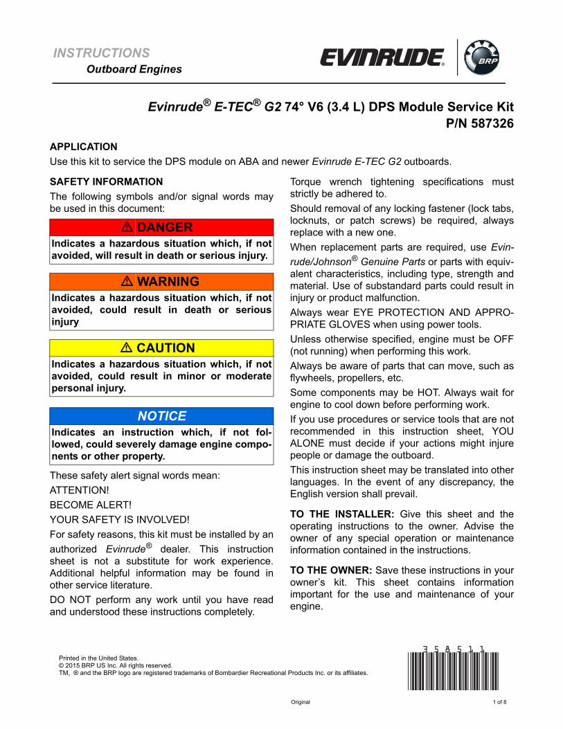
The DPS Module Service Kit includes the compo-nents shown below.
DPS Module RemovalRemove the top, port, front and rear covers. Nextremove the port and front frames. Refer to EngineCover and Frame Service in the correct ServiceManual.
Disconnect the electrical connectors from theDPS module.
Remove the Oetiker clamps from the upper andlower cooling hoses, then remove the coolinghoses from the DPS module.
Remove the ground wire from the ground screwon the engine block.
Remove the three DPS module mounting screwsand washers.
Remove the DPS module from the engine.
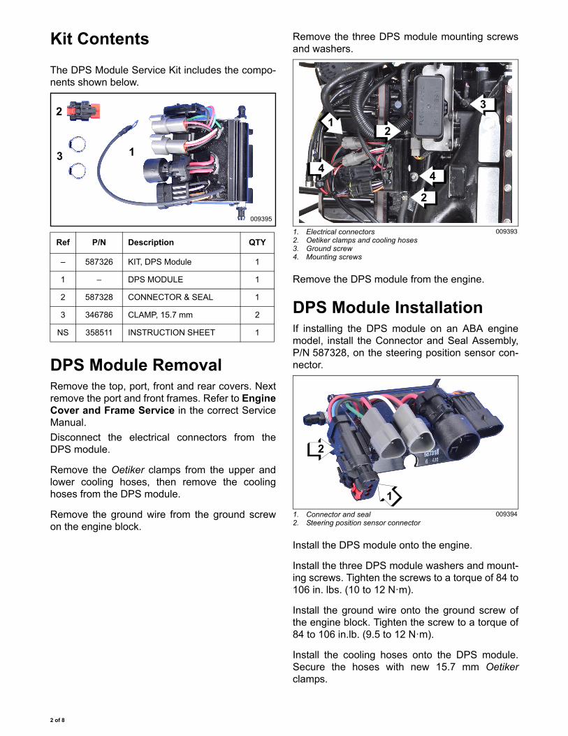
DPS Module InstallationIf installing the DPS module on an ABA enginemodel, install the Connector and Seal Assembly,P/N 587328, on the steering position sensor con-nector.
Install the DPS module onto the engine.
Install the three DPS module washers and mount-ing screws. Tighten the screws to a torque of 84 to106 in. lbs. (10 to 12 N·m).
Install the ground wire onto the ground screw ofthe engine block. Tighten the screw to a torque of84 to 106 in.lb. (9.5 to 12 N·m).
Install the cooling hoses onto the DPS module.Secure the hoses with new 15.7 mm Oetikerclamps.
Ref P/N Description QTY
– 587326 KIT, DPS Module 1
1 – DPS MODULE 1
2 587328 CONNECTOR & SEAL 1
3 346786 CLAMP, 15.7 mm 2
NS 358511 INSTRUCTION SHEET 1
1
2
3
009395
1. Electrical connectors2. Oetiker clamps and cooling hoses3. Ground screw4. Mounting screws
009393
1. Connector and seal2. Steering position sensor connector
009394
2
4
3
21
4
2
1
2 of 8
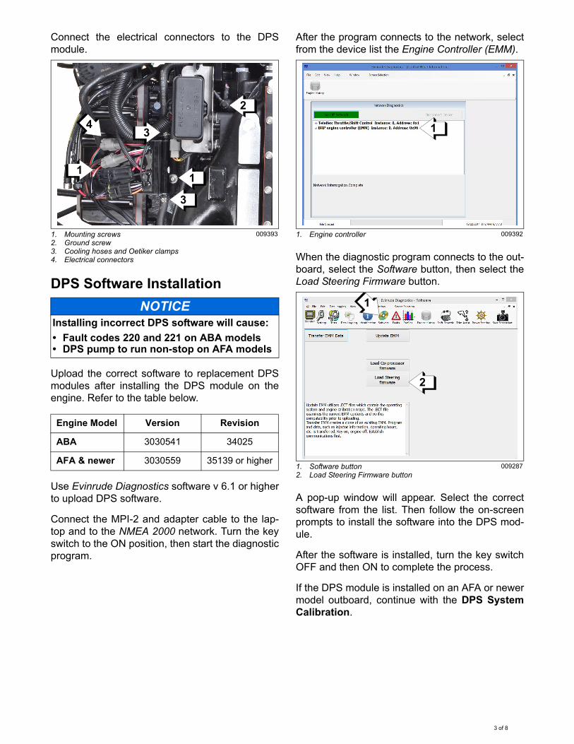
Connect the electrical connectors to the DPSmodule.
DPS Software Installation
Upload the correct software to replacement DPSmodules after installing the DPS module on theengine. Refer to the table below.
Use Evinrude Diagnostics software v 6.1 or higherto upload DPS software.
Connect the MPI-2 and adapter cable to the lap-top and to the NMEA 2000 network. Turn the keyswitch to the ON position, then start the diagnosticprogram.
After the program connects to the network, selectfrom the device list the Engine Controller (EMM).
When the diagnostic program connects to the out-board, select the Software button, then select theLoad Steering Firmware button.
A pop-up window will appear. Select the correctsoftware from the list. Then follow the on-screenprompts to install the software into the DPS mod-ule.
After the software is installed, turn the key switchOFF and then ON to complete the process.
If the DPS module is installed on an AFA or newermodel outboard, continue with the DPS SystemCalibration.
1. Mounting screws2. Ground screw3. Cooling hoses and Oetiker clamps4. Electrical connectors
009393
NOTICEInstalling incorrect DPS software will cause:
• Fault codes 220 and 221 on ABA models• DPS pump to run non-stop on AFA models
Engine Model Version Revision
ABA 3030541 34025
AFA & newer 3030559 35139 or higher
3
1
2
34
1
1. Engine controller 009392
1. Software button2. Load Steering Firmware button
009287
1
2
1
3 of 8
DPS System Calibration
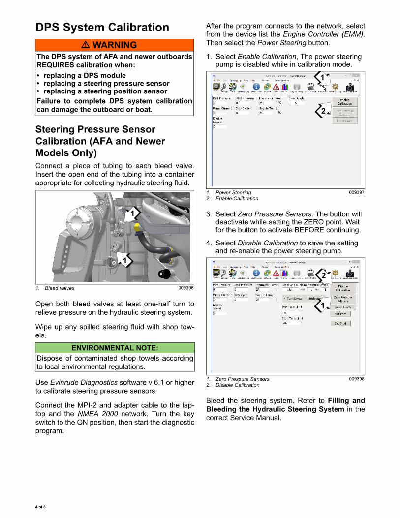
Steering Pressure Sensor Calibration (AFA and Newer Models Only)Connect a piece of tubing to each bleed valve.Insert the open end of the tubing into a containerappropriate for collecting hydraulic steering fluid.
Open both bleed valves at least one-half turn torelieve pressure on the hydraulic steering system.
Wipe up any spilled steering fluid with shop tow-els.
Use Evinrude Diagnostics software v 6.1 or higherto calibrate steering pressure sensors.
Connect the MPI-2 and adapter cable to the lap-top and the NMEA 2000 network. Turn the keyswitch to the ON position, then start the diagnosticprogram.
After the program connects to the network, selectfrom the device list the Engine Controller (EMM).Then select the Power Steering button.
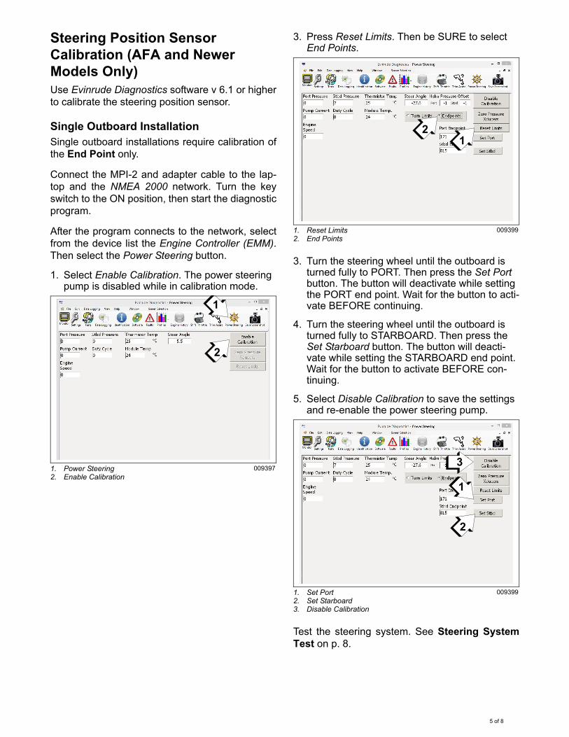
1. Select Enable Calibration, The power steering pump is disabled while in calibration mode.
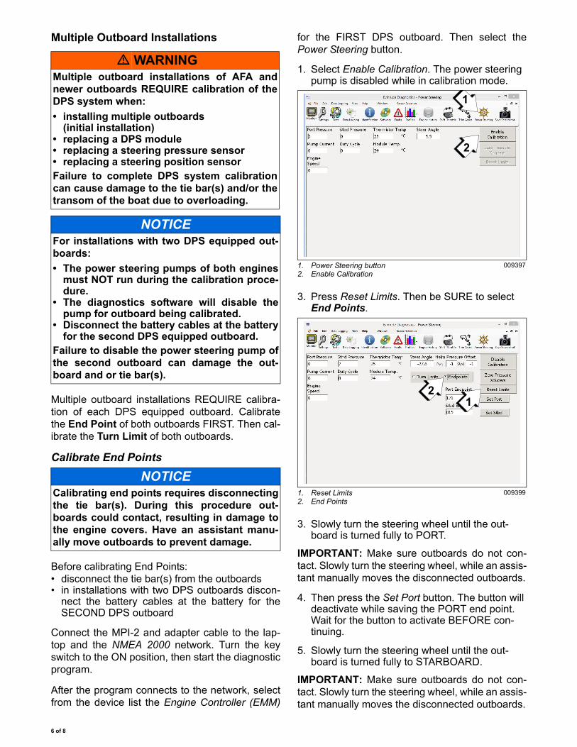
3. Select Zero Pressure Sensors. The button will deactivate while setting the ZERO point. Wait for the button to activate BEFORE continuing.
4. Select Disable Calibration to save the setting and re-enable the power steering pump.
Bleed the steering system. Refer to Filling andBleeding the Hydraulic Steering System in thecorrect Service Manual.
� WARNINGThe DPS system of AFA and newer outboardsREQUIRES calibration when:
• replacing a DPS module• replacing a steering pressure sensor• replacing a steering position sensorFailure to complete DPS system calibrationcan damage the outboard or boat.
1. Bleed valves 009396
ENVIRONMENTAL NOTE:
Dispose of contaminated shop towels accordingto local environmental regulations.
1
1
1. Power Steering2. Enable Calibration
009397
1. Zero Pressure Sensors2. Disable Calibration
009398
1
2
1
2
4 of 8
Steering Position Sensor Calibration (AFA and Newer Models Only)Use Evinrude Diagnostics software v 6.1 or higherto calibrate the steering position sensor.
Single Outboard InstallationSingle outboard installations require calibration ofthe End Point only.
Connect the MPI-2 and adapter cable to the lap-top and the NMEA 2000 network. Turn the keyswitch to the ON position, then start the diagnosticprogram.
After the program connects to the network, selectfrom the device list the Engine Controller (EMM).Then select the Power Steering button.
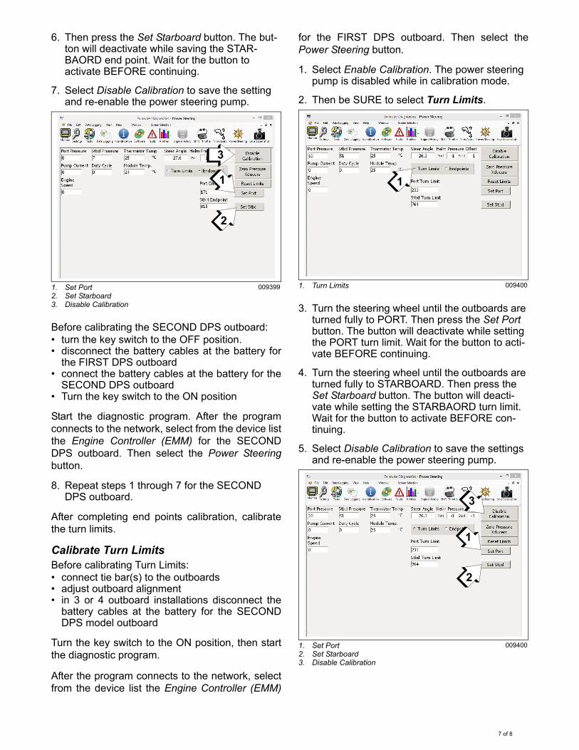
1. Select Enable Calibration. The power steering pump is disabled while in calibration mode.
3. Press Reset Limits. Then be SURE to select End Points.
3. Turn the steering wheel until the outboard is turned fully to PORT. Then press the Set Port button. The button will deactivate while setting the PORT end point. Wait for the button to acti-vate BEFORE continuing.
4. Turn the steering wheel until the outboard is turned fully to STARBOARD. Then press the Set Starboard button. The button will deacti-vate while setting the STARBOARD end point. Wait for the button to activate BEFORE con-tinuing.
5. Select Disable Calibration to save the settings and re-enable the power steering pump.
Test the steering system. See Steering SystemTest on p. 8.
1. Power Steering2. Enable Calibration
009397
1
2
1. Reset Limits2. End Points
009399
1. Set Port2. Set Starboard3. Disable Calibration
009399
21
3
1
2
5 of 8
Multiple Outboard Installations
Multiple outboard installations REQUIRE calibra-tion of each DPS equipped outboard. Calibratethe End Point of both outboards FIRST. Then cal-ibrate the Turn Limit of both outboards.
Calibrate End Points
Before calibrating End Points:• disconnect the tie bar(s) from the outboards• in installations with two DPS outboards discon-
nect the battery cables at the battery for theSECOND DPS outboard
Connect the MPI-2 and adapter cable to the lap-top and the NMEA 2000 network. Turn the keyswitch to the ON position, then start the diagnosticprogram.
After the program connects to the network, selectfrom the device list the Engine Controller (EMM)
for the FIRST DPS outboard. Then select thePower Steering button.
1. Select Enable Calibration. The power steering pump is disabled while in calibration mode.
3. Press Reset Limits. Then be SURE to select End Points.
3. Slowly turn the steering wheel until the out-board is turned fully to PORT.
IMPORTANT: Make sure outboards do not con-tact. Slowly turn the steering wheel, while an assis-tant manually moves the disconnected outboards.
4. Then press the Set Port button. The button will deactivate while saving the PORT end point. Wait for the button to activate BEFORE con-tinuing.
5. Slowly turn the steering wheel until the out-board is turned fully to STARBOARD.
IMPORTANT: Make sure outboards do not con-tact. Slowly turn the steering wheel, while an assis-tant manually moves the disconnected outboards.
� WARNINGMultiple outboard installations of AFA andnewer outboards REQUIRE calibration of theDPS system when:
• installing multiple outboards(initial installation)
• replacing a DPS module• replacing a steering pressure sensor• replacing a steering position sensorFailure to complete DPS system calibrationcan cause damage to the tie bar(s) and/or thetransom of the boat due to overloading.
NOTICEFor installations with two DPS equipped out-boards:
• The power steering pumps of both enginesmust NOT run during the calibration proce-dure.
• The diagnostics software will disable thepump for outboard being calibrated.
• Disconnect the battery cables at the batteryfor the second DPS equipped outboard.
Failure to disable the power steering pump ofthe second outboard can damage the out-board and or tie bar(s).
NOTICECalibrating end points requires disconnectingthe tie bar(s). During this procedure out-boards could contact, resulting in damage tothe engine covers. Have an assistant manu-ally move outboards to prevent damage.
1. Power Steering button2. Enable Calibration
009397
1. Reset Limits2. End Points
009399
1
2
21
6 of 8
6. Then press the Set Starboard button. The but-ton will deactivate while saving the STAR-BAORD end point. Wait for the button to activate BEFORE continuing.
7. Select Disable Calibration to save the setting and re-enable the power steering pump.
Before calibrating the SECOND DPS outboard:• turn the key switch to the OFF position.• disconnect the battery cables at the battery for
the FIRST DPS outboard• connect the battery cables at the battery for the
SECOND DPS outboard• Turn the key switch to the ON position
Start the diagnostic program. After the programconnects to the network, select from the device listthe Engine Controller (EMM) for the SECONDDPS outboard. Then select the Power Steeringbutton.
8. Repeat steps 1 through 7 for the SECOND DPS outboard.
After completing end points calibration, calibratethe turn limits.
Calibrate Turn LimitsBefore calibrating Turn Limits:• connect tie bar(s) to the outboards• adjust outboard alignment• in 3 or 4 outboard installations disconnect the
battery cables at the battery for the SECONDDPS model outboard
Turn the key switch to the ON position, then startthe diagnostic program.
After the program connects to the network, selectfrom the device list the Engine Controller (EMM)
for the FIRST DPS outboard. Then select thePower Steering button.
1. Select Enable Calibration. The power steering pump is disabled while in calibration mode.
2. Then be SURE to select Turn Limits.
3. Turn the steering wheel until the outboards are turned fully to PORT. Then press the Set Port button. The button will deactivate while setting the PORT turn limit. Wait for the button to acti-vate BEFORE continuing.
4. Turn the steering wheel until the outboards are turned fully to STARBOARD. Then press the Set Starboard button. The button will deacti-vate while setting the STARBAORD turn limit. Wait for the button to activate BEFORE con-tinuing.
5. Select Disable Calibration to save the settings and re-enable the power steering pump.
1. Set Port2. Set Starboard3. Disable Calibration
009399
3
1
2
1. Turn Limits 009400
1. Set Port2. Set Starboard3. Disable Calibration
009400
1
1
2
3
7 of 8

Before calibrating the SECOND DPS outboard:• turn the key switch to the OFF position.• disconnect the battery cables at the battery for
the FIRST DPS outboard• connect the battery cables at the battery for the
SECOND DPS outboard• Turn the key switch to the ON position
6. Repeat steps 1 through 5 for the SECOND DPS outboard.
Connect the battery cables at the battery, then testthe steering system.
Steering System TestTurn the steering wheel fully to PORT. The powersteering pump should run, then shut OFF whenthe engine is turned fully to PORT.
Turn the steering wheel fully to STARBOARD. Thepower steering pump should run, then shut OFFwhen the engine is turned fully to STARBOARD.
In some installations it may be difficult to hear thepower steering pump run. Use the Power Steeringscreen of Evinrude Diagnostics software to moni-tor the pump Current and Duty Cycle.
These values should be zero when the pump isNOT running.
Cover and Frame InstallationInstall the front and port frames. Then install thetop, port, front and rear covers. Refer to EngineCover and Frame Service in the correct ServiceManual.
1. Pump Current2. Duty Cycle
009401
1 2
8 of 8