Embed Size (px)
Citation preview
EVK-M8QSAM Evaluation Kit User Guide
Abstract
This document describes the structure and use of the EVK-M8QSAM evaluation kit and provides information for evaluating and testing the
u-blox SAM-M8Q GNSS patch antenna module.
www.u-blox.com
UBX-16018104 - R06
EVK-M8QSAM - User Guide
UBX-16018104 - R06 Early Production Information Page 2 of 23
Document Information
Title EVK-M8QSAM
Subtitle Evaluation Kit
Document type User Guide
Document number UBX-16018104
Revision and Date R06 30-Nov-2017
Document status Early Production Information
Document status explanation
Objective Specification Document contains target values. Revised and supplementary data will be published later.
Advance Information Document contains data based on early testing. Revised and supplementary data will be published later.
Early Production Information Document contains data from product verification. Revised and supplementary data may be published later.
Production Information Document contains the final product specification.
European Union regulatory compliance
EVK-M8QSAM complies with all relevant requirements for RED 2014/53/EU. The EVK-M8QSAM Declaration of Conformity (DoC) is available at www.u-blox.com (Support --> Product Resources --> Conformity Declaration).
This document applies to the following products:
Product name Type number Firmware version PCN reference
EVK-M8QSAM EVK-M8QSAM-0-00 ROM SPG 3.01 N/A
u-blox reserves all rights to this document and the information contained herein. Products, names, logos and designs described herein may in whole or in part be subject to intellectual property rights. Reproduction, use, modification or disclosure to third parties of this
document or any part thereof without the express permission of u-blox is strictly prohibited.
The information contained herein is provided “as is” and u-blox assumes no liability for the use of the information. No warranty, either express or implied, is given, including but not limited, with respect to the accuracy, correctness, reliability and fitness for a particular purpose of the information. This document may be revised by u-blox at any time. For most recent documents, visit www.u-blox.com.
Copyright © 2017, u-blox AG.
u-blox is a registered trademark of u-blox Holding AG in the EU and other countries.
EVK-M8QSAM User Guide
UBX-16018104 - R06 Early Production Information Preface
Page 3 of 23
Preface
Using this guide
This guide assumes, the user has basic computer skills and is familiar with the Windows Graphical User Interface
(GUI) and GNSS receiver environments.
The following symbols are used in the document to highlight information:
A warning symbol indicates actions that could negatively impact or damage the device.
An index finger points out key information pertaining to device operation and performance.
Warnings and certifications
EVK-M8QSAM is an Electrostatic Sensitive Device (ESD).
CAUTION! RISK OF SHORT CIRCUIT OF THE BATTERY WHEN TOUCHING IT WITH
CONDUCTING PARTS. IN THE UNLIKELY EVENT OF A FAILURE IN THE INTERNAL
PROTECTION CIRCUITRY THERE IS A RISK OF AN EXPLOSION WHEN CHARGING FULLY OR PARTIALLY DISCHARGED BATTERIES. REPLACE THE BATTERY IF IT NO
LONGER HAS SUFFICIENT CHARGE FOR UNIT OPERATION. CONTROL THE BATTERY
BEFORE USING IF THE DEVICE HAS NOT BEEN OPERATED FOR AN EXTENDED PERIOD OF TIME.
Products marked with this lead-free symbol on the product label comply with the “Directive 2002/95/EC and Directive 2011/65/EU of the European Parliament and the
Council on the Restriction of Use of certain Hazardous Substances in Electrical and
Electronic Equipment” (RoHS).
EVK-M8QSAM evaluation kit is RoHS compliant and green (no halogens).
EVK-M8QSAM User Guide
UBX-16018104 - R06 Early Production Information Contents
Page 4 of 23
Contents
Preface ................................................................................................................................ 3
Using this guide ............................................................................................................................................... 3
Warnings and certifications ............................................................................................................................. 3
Contents .............................................................................................................................. 4
1 Product description ...................................................................................................... 6
1.1 Overview .............................................................................................................................................. 6
1.2 Kit includes ........................................................................................................................................... 6
1.3 Software and documentation ............................................................................................................... 6
1.4 u-center GNSS evaluation software ....................................................................................................... 6
1.5 System requirements ............................................................................................................................ 6
2 Specifications ................................................................................................................ 7
2.1 Safety precautions ................................................................................................................................ 7
3 Getting Started ............................................................................................................. 8
3.1 Software installation ............................................................................................................................. 8
3.2 Hardware installation ............................................................................................................................ 8
3.3 Serial port default configuration ........................................................................................................... 8
4 Device description ........................................................................................................ 9
4.1 Interface connection and measurement ................................................................................................ 9
4.2 Active antenna ..................................................................................................................................... 9
4.3 Evaluation unit ...................................................................................................................................... 9
4.3.1 Antenna connector ..................................................................................................................... 10
4.3.2 USB ............................................................................................................................................. 10
4.3.3 UART ........................................................................................................................................... 10
4.3.4 Time pulse ................................................................................................................................... 10
4.3.5 RST button .................................................................................................................................. 11
4.3.6 Safe boot button ......................................................................................................................... 11
4.3.7 Slide Switch ................................................................................................................................. 11
4.3.8 Test Connector ............................................................................................................................ 11
4.3.9 LED ............................................................................................................................................. 12
4.3.10 Backup Battery ............................................................................................................................ 12
4.3.11 GNSS Configuration .................................................................................................................... 12
4.3.12 AssistNowTM
Autonomous ............................................................................................................ 12
5 Measuring tracking current ....................................................................................... 13
6 Testing Power Save Mode ......................................................................................... 14
7 Block diagram ............................................................................................................. 15
EVK-M8QSAM User Guide
UBX-16018104 - R06 Early Production Information Contents
Page 5 of 23
8 Board layout ............................................................................................................... 16
9 Schematic .................................................................................................................... 18
10 Troubleshooting ......................................................................................................... 19
11 Common evaluation pitfalls ...................................................................................... 21
Related documents........................................................................................................... 22
Revision history ................................................................................................................ 22
Contact .............................................................................................................................. 23
EVK-M8QSAM User Guide
UBX-16018104 - R06 Early Production Information Product description
Page 6 of 23
1 Product description
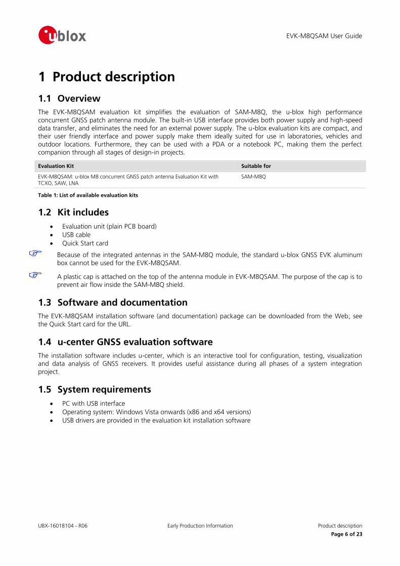
1.1 Overview
The EVK-M8QSAM evaluation kit simplifies the evaluation of SAM-M8Q, the u-blox high performance
concurrent GNSS patch antenna module. The built-in USB interface provides both power supply and high-speed
data transfer, and eliminates the need for an external power supply. The u-blox evaluation kits are compact, and their user friendly interface and power supply make them ideally suited for use in laboratories, vehicles and
outdoor locations. Furthermore, they can be used with a PDA or a notebook PC, making them the perfect
companion through all stages of design-in projects.
Evaluation Kit Suitable for
EVK-M8QSAM: u-blox M8 concurrent GNSS patch antenna Evaluation Kit with TCXO, SAW, LNA
SAM-M8Q
Table 1: List of available evaluation kits
1.2 Kit includes
Evaluation unit (plain PCB board)
USB cable
Quick Start card
Because of the integrated antennas in the SAM-M8Q module, the standard u-blox GNSS EVK aluminum
box cannot be used for the EVK-M8QSAM.
A plastic cap is attached on the top of the antenna module in EVK-M8QSAM. The purpose of the cap is to prevent air flow inside the SAM-M8Q shield.
1.3 Software and documentation
The EVK-M8QSAM installation software (and documentation) package can be downloaded from the Web; see
the Quick Start card for the URL.
1.4 u-center GNSS evaluation software
The installation software includes u-center, which is an interactive tool for configuration, testing, visualization
and data analysis of GNSS receivers. It provides useful assistance during all phases of a system integration
project.
1.5 System requirements
PC with USB interface
Operating system: Windows Vista onwards (x86 and x64 versions)
USB drivers are provided in the evaluation kit installation software
EVK-M8QSAM User Guide
UBX-16018104 - R06 Early Production Information Specifications
Page 7 of 23
2 Specifications Parameter Specification
Serial Interfaces 1 USB V2.0
1 RS232, max. baud rate 460,8 kBd
- DB9: PC compatible
1 DDC (I2C compatible) max. 400 kHz
Timing Interfaces 1 Time pulse output
Dimensions 100 x 60 x 26 mm
Power Supply 5 V via USB or external powered via extra power supply pin 14 (V5_IN) 13 (GND)
Normal Operating temperature -40°C to +65°C
Table 2: EVK-M8QSAM specification
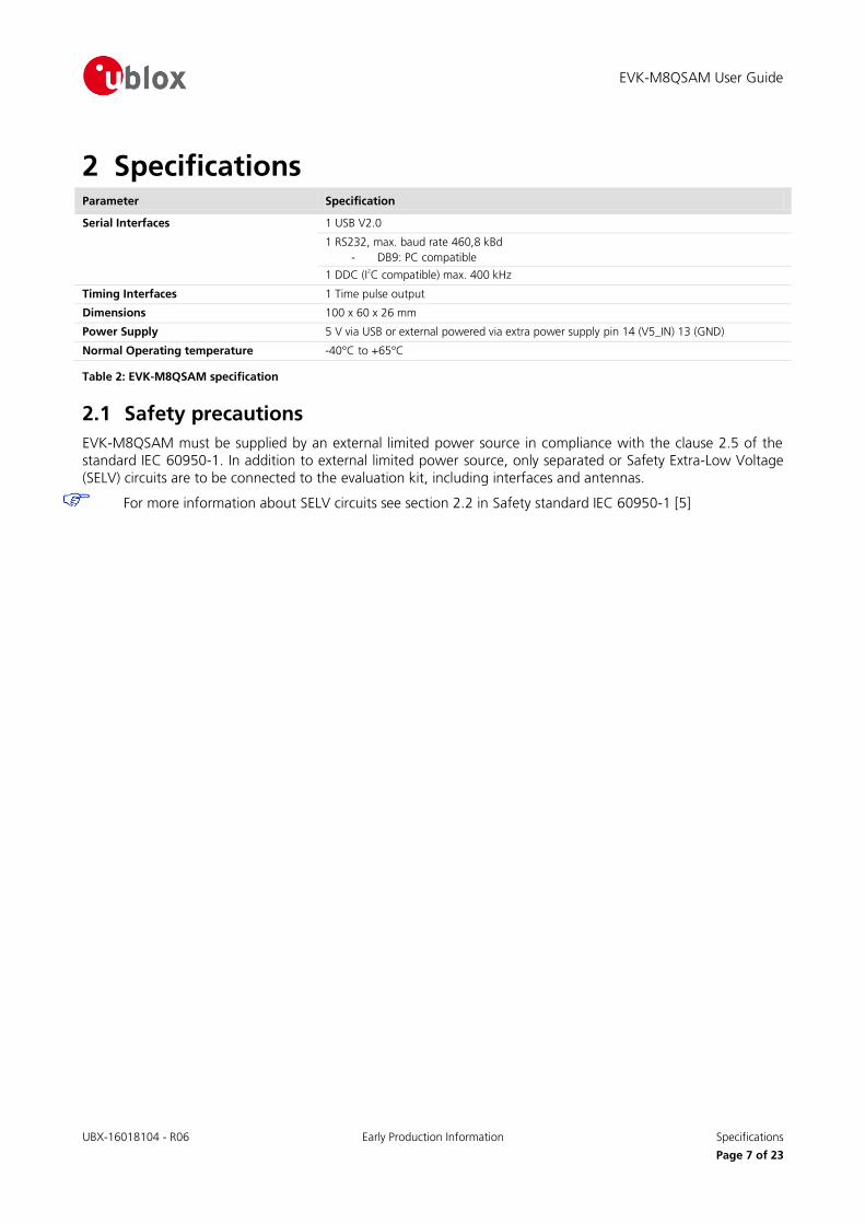
2.1 Safety precautions
EVK-M8QSAM must be supplied by an external limited power source in compliance with the clause 2.5 of the
standard IEC 60950-1. In addition to external limited power source, only separated or Safety Extra-Low Voltage
(SELV) circuits are to be connected to the evaluation kit, including interfaces and antennas.
For more information about SELV circuits see section 2.2 in Safety standard IEC 60950-1 [5]

EVK-M8QSAM User Guide
UBX-16018104 - R06 Early Production Information Getting Started
Page 8 of 23
3 Getting Started
3.1 Software installation
Installation of the EVK-M8QSAM software and documentation requires Internet access.
Choose the “Software only” or “Software and documentation” installation package from the u-blox website.
Once the zip file is downloaded, unzip the file in the Tools folder and double-click the extracted exe file.
The software components will be installed on your system and placed under the “u-blox” folder in the “Start
Programs” menu.
3.2 Hardware installation
1. Connect the unit to a PC running Microsoft Windows. Options:
USB: Connect via USB port. Set slide switch to USB.
UART: Connect via RS232. Set slide switch to RS232.
2. The device must always have power, either via USB on the back or the V5_IN input on the front.
3. The EVK-M8QSAM evaluation kit includes a SAM-M8Q concurrent GNSS module with embedded patch
antenna. There is no external antenna connectivity to RF IN. Place the evaluation kit in a location with good sky view.
4. Start the u-center GNSS Evaluation Software and select the corresponding COM port and baud rate. (Refer
to the u-center User Guide [4] for more information.)
3.3 Serial port default configuration
Parameter Description Remark
UART Port 1, Input UBX and NMEA protocol at 9600 Bd
UART Port 1, Output UBX and NMEA protocol at 9600 Bd Only NMEA messages are activated
USB, Input UBX and NMEA protocol
USB, Output UBX and NMEA protocol Only NMEA messages are activated
Table 3: Default configuration
EVK-M8QSAM User Guide
UBX-16018104 - R06 Early Production Information Device description
Page 9 of 23
4 Device description
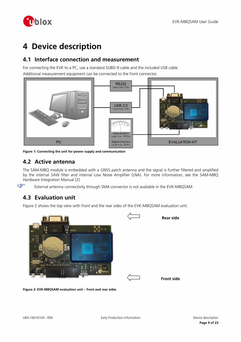
4.1 Interface connection and measurement
For connecting the EVK to a PC, use a standard SUBD-9 cable and the included USB cable.
Additional measurement equipment can be connected to the front connector.
Figure 1: Connecting the unit for power supply and communication
4.2 Active antenna
The SAM-M8Q module is embedded with a GNSS patch antenna and the signal is further filtered and amplified
by the internal SAW filter and internal Low Noise Amplifier (LNA). For more information, see the SAM-M8Q Hardware Integration Manual [2].
External antenna connectivity through SMA connector is not available in the EVK-M8QSAM.
4.3 Evaluation unit
Figure 2 shows the top view with front and the rear sides of the EVK-M8QSAM evaluation unit.
Rear side
Front side
Figure 2: EVK-M8QSAM evaluation unit – front and rear sides
EVK-M8QSAM User Guide
UBX-16018104 - R06 Early Production Information Device description
Page 10 of 23
4.3.1 Antenna connector
No antenna connector is provided for the EVK-M8QSAM evaluation kit.
4.3.2 USB
A USB V2.0 compatible serial port is featured for data communication and power supply.
4.3.3 UART
The evaluation unit includes an RS232 port for serial communication that is compatible with PC serial ports. In addition to the RS232 communication port, the time pulse 1 signal is available on the DB9 connector (Pin 1 or 6).
Connect using a straight RS232 serial cable with male and female connectors to the port on your PC. The
maximum cable length is 3 meters. To configure the RS232 port, use the CFG_PRT command in the u-center application. The maximum operating baud rate is 460.8 kBd.
If you are using a USB to RS232 adaptor cable, you can connect it directly to the evaluation kit RS232 port.
The 9-pin D-SUB female connector is assigned as listed in Table 4:
Pin Nr. Assignment
1 GNSS time pulse output
2 TXD, GNSS Transmit Data, serial data to DTE
3 RXD, GNSS Receive Data, serial data from DTE
4 not connected
5 GND
6 GNSS time pulse output
7-9 not connected
Table 4: SUB-D9 Connector pin description for EVK-M8QSAM
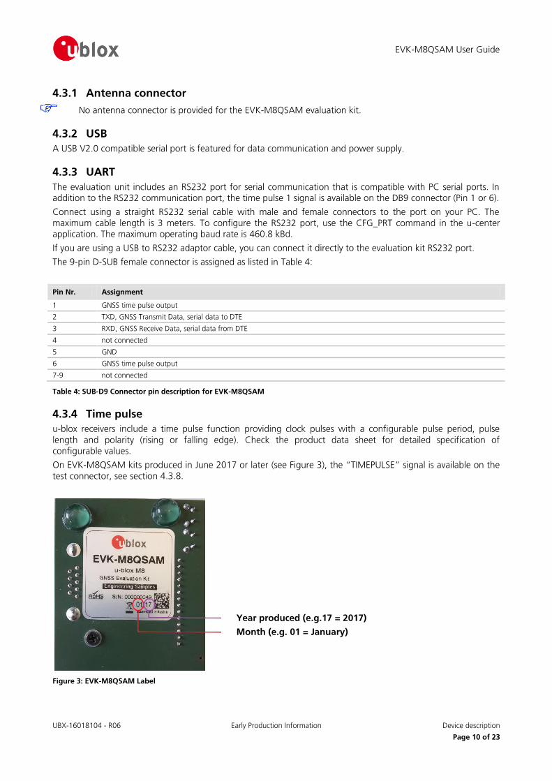
4.3.4 Time pulse
u-blox receivers include a time pulse function providing clock pulses with a configurable pulse period, pulse
length and polarity (rising or falling edge). Check the product data sheet for detailed specification of configurable values.
On EVK-M8QSAM kits produced in June 2017 or later (see Figure 3), the “TIMEPULSE” signal is available on the
test connector, see section 4.3.8.
Figure 3: EVK-M8QSAM Label
Year produced (e.g.17 = 2017)
Month (e.g. 01 = January)
EVK-M8QSAM User Guide
UBX-16018104 - R06 Early Production Information Device description
Page 11 of 23
4.3.5 RST button
The RST button on the front side resets the unit. To avoid an inadvertent reset, the button is recessed.
4.3.6 Safe boot button
This is used to set the unit in safe boot mode. In this mode the receiver executes only the minimal functionality.
In order to set the receiver in safe boot mode please follow these steps.
1. Press the BOOT button and keep holding
2. Press the RST button
3. Release the RST button 4. Release the BOOT button
5. If the UART interface has to be used, the training sequence has to be sent to the receiver.
The training sequence is a transmission of 0x55 55 at the baud rate of 9600 Bd. Wait for at least 100 milliseconds before the interface is ready to accept commands.
4.3.7 Slide Switch
Use the slide switch on the front side to choose between RS232 and USB communication ports.
1. RS232 – In this selection the EVK operates with the RS232 (DB9 – rear side).
2. USB – In this selection the EVK operates only with the USB interface. RS232 (DB9) is switched off.
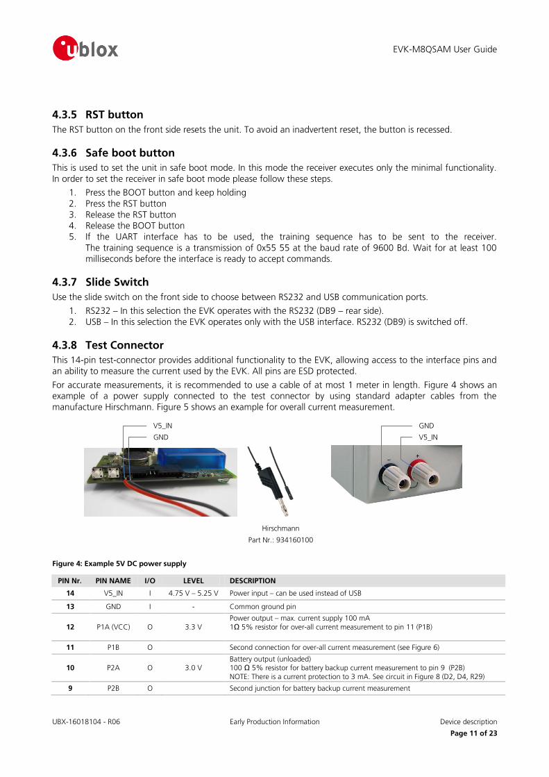
4.3.8 Test Connector
This 14-pin test-connector provides additional functionality to the EVK, allowing access to the interface pins and
an ability to measure the current used by the EVK. All pins are ESD protected.
For accurate measurements, it is recommended to use a cable of at most 1 meter in length. Figure 4 shows an example of a power supply connected to the test connector by using standard adapter cables from the
manufacture Hirschmann. Figure 5 shows an example for overall current measurement.
PIN Nr.: PIN NAME I/O LEVEL DESCRIPTION
14 V5_IN I 4.75 V – 5.25 V Power input – can be used instead of USB
13 GND I - Common ground pin
12 P1A (VCC) O 3.3 V Power output – max. current supply 100 mA 1Ω 5% resistor for over-all current measurement to pin 11 (P1B)
11 P1B O Second connection for over-all current measurement (see Figure 6)
10 P2A O 3.0 V Battery output (unloaded) 100 Ω 5% resistor for battery backup current measurement to pin 9 (P2B) NOTE: There is a current protection to 3 mA. See circuit in Figure 8 (D2, D4, R29)
9 P2B O Second junction for battery backup current measurement
Figure 4: Example 5V DC power supply
V5_IN
GND
GND
V5_IN
Hirschmann
Part Nr.: 934160100
EVK-M8QSAM User Guide
UBX-16018104 - R06 Early Production Information Device description
Page 12 of 23
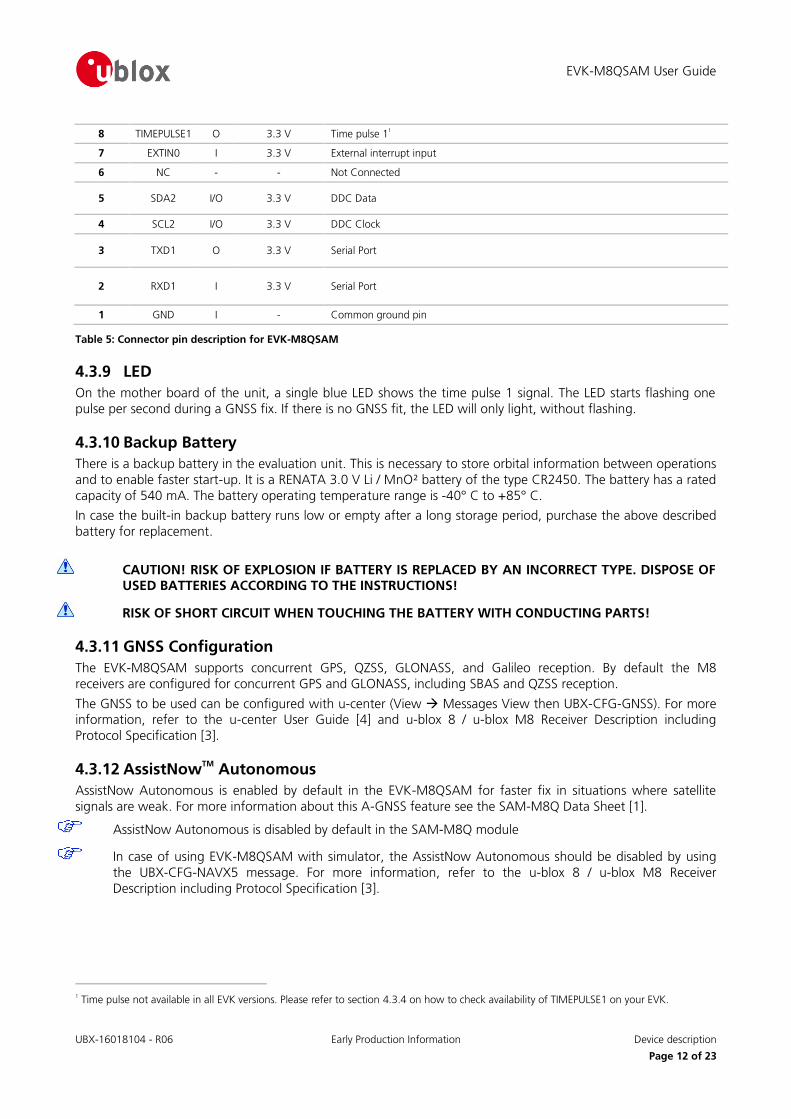
8 TIMEPULSE1 O 3.3 V Time pulse 11
7 EXTIN0 I 3.3 V External interrupt input
6 NC - - Not Connected
5 SDA2 I/O 3.3 V DDC Data
4 SCL2 I/O 3.3 V DDC Clock
3 TXD1 O 3.3 V Serial Port
2 RXD1 I 3.3 V Serial Port
1 GND I - Common ground pin
Table 5: Connector pin description for EVK-M8QSAM
4.3.9 LED
On the mother board of the unit, a single blue LED shows the time pulse 1 signal. The LED starts flashing one
pulse per second during a GNSS fix. If there is no GNSS fit, the LED will only light, without flashing.
4.3.10 Backup Battery
There is a backup battery in the evaluation unit. This is necessary to store orbital information between operations
and to enable faster start-up. It is a RENATA 3.0 V Li / MnO² battery of the type CR2450. The battery has a rated
capacity of 540 mA. The battery operating temperature range is -40° C to +85° C.
In case the built-in backup battery runs low or empty after a long storage period, purchase the above described
battery for replacement.
CAUTION! RISK OF EXPLOSION IF BATTERY IS REPLACED BY AN INCORRECT TYPE. DISPOSE OF USED BATTERIES ACCORDING TO THE INSTRUCTIONS!
RISK OF SHORT CIRCUIT WHEN TOUCHING THE BATTERY WITH CONDUCTING PARTS!
4.3.11 GNSS Configuration
The EVK-M8QSAM supports concurrent GPS, QZSS, GLONASS, and Galileo reception. By default the M8
receivers are configured for concurrent GPS and GLONASS, including SBAS and QZSS reception.
The GNSS to be used can be configured with u-center (View Messages View then UBX-CFG-GNSS). For more information, refer to the u-center User Guide [4] and u-blox 8 / u-blox M8 Receiver Description including
Protocol Specification [3].
4.3.12 AssistNowTM
Autonomous
AssistNow Autonomous is enabled by default in the EVK-M8QSAM for faster fix in situations where satellite
signals are weak. For more information about this A-GNSS feature see the SAM-M8Q Data Sheet [1].
AssistNow Autonomous is disabled by default in the SAM-M8Q module
In case of using EVK-M8QSAM with simulator, the AssistNow Autonomous should be disabled by using
the UBX-CFG-NAVX5 message. For more information, refer to the u-blox 8 / u-blox M8 Receiver
Description including Protocol Specification [3].
1 Time pulse not available in all EVK versions. Please refer to section 4.3.4 on how to check availability of TIMEPULSE1 on your EVK.
EVK-M8QSAM User Guide
UBX-16018104 - R06 Early Production Information Measuring tracking current
Page 13 of 23
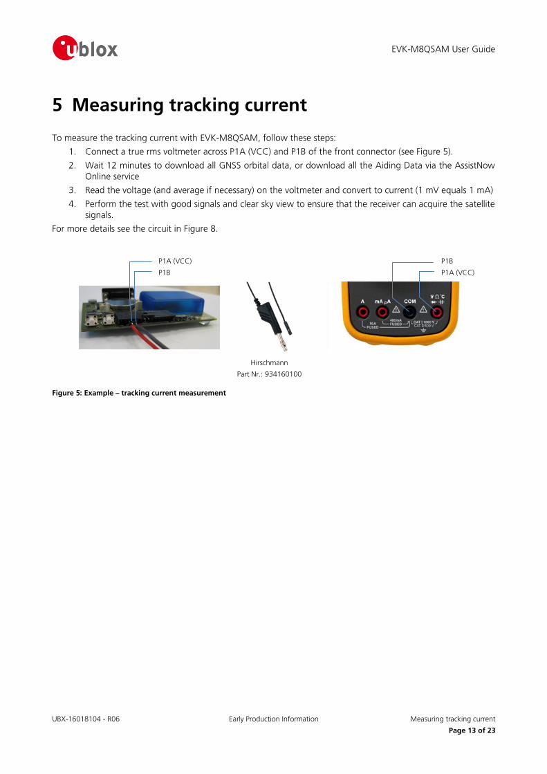
5 Measuring tracking current
To measure the tracking current with EVK-M8QSAM, follow these steps:
1. Connect a true rms voltmeter across P1A (VCC) and P1B of the front connector (see Figure 5).
2. Wait 12 minutes to download all GNSS orbital data, or download all the Aiding Data via the AssistNow
Online service
3. Read the voltage (and average if necessary) on the voltmeter and convert to current (1 mV equals 1 mA)
4. Perform the test with good signals and clear sky view to ensure that the receiver can acquire the satellite
signals.
For more details see the circuit in Figure 8.
Figure 5: Example – tracking current measurement
Hirschmann
Part Nr.: 934160100
P1A (VCC)
P1B
P1B
P1A (VCC)

EVK-M8QSAM User Guide
UBX-16018104 - R06 Early Production Information Testing Power Save Mode
Page 14 of 23
6 Testing Power Save Mode When testing Power Save Mode with EVK-M8QSAM, observe the following points:
A set of predefined power mode setups can be selected using the CFG-PMS message. The Configuration view or Messages view of the u-center evaluation software can be used to do this. When enabling the mode
using CFG-PMS, always save the configuration by checking the “save configuration” box in u-center
otherwise the configuration will be lost.
Selecting one of the available setups is the equivalent of using a combination of the configuration messages
with appropriate parameters that impact the power consumption of the receiver.
u-blox recommends using these predefined settings, except where users have very specific power saving
requirements
Note that polling UBX-CFG-PMS will return the setup only if the full configuration is consistent with one of the predefined Power Mode Setups
Communication to the evaluation kit must be via the RS232 or the USB.
The evaluation kit can be supplied via the USB connector or via V5_IN at the front side connector.
EVK-M8QSAM User Guide
UBX-16018104 - R06 Early Production Information Block diagram
Page 15 of 23
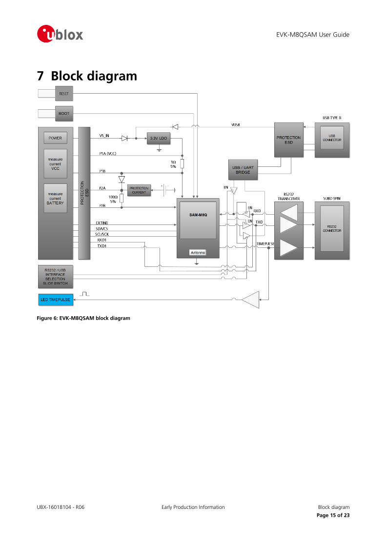
7 Block diagram
Figure 6: EVK-M8QSAM block diagram
EVK-M8QSAM User Guide
UBX-16018104 - R06 Early Production Information Board layout
Page 16 of 23
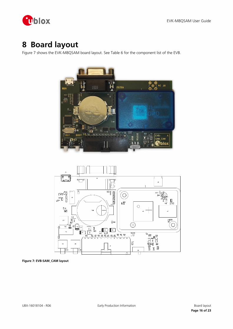
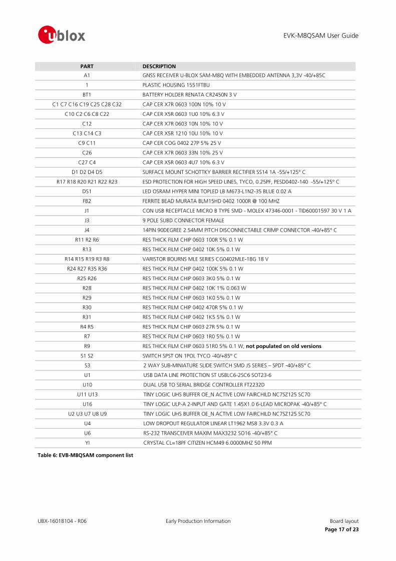
8 Board layout Figure 7 shows the EVK-M8QSAM board layout. See Table 6 for the component list of the EVB.
Figure 7: EVB-SAM_CAM layout
EVK-M8QSAM User Guide
UBX-16018104 - R06 Early Production Information Board layout
Page 17 of 23
PART DESCRIPTION
A1 GNSS RECEIVER U-BLOX SAM-M8Q WITH EMBEDDED ANTENNA 3,3V -40/+85C
1 PLASTIC HOUSING 1551FTBU
BT1 BATTERY HOLDER RENATA CR2450N 3 V
C1 C7 C16 C19 C25 C28 C32 CAP CER X7R 0603 100N 10% 10 V
C10 C2 C6 C8 C22 CAP CER X5R 0603 1U0 10% 6.3 V
C12 CAP CER X7R 0603 10N 10% 10 V
C13 C14 C3 CAP CER X5R 1210 10U 10% 10 V
C9 C11 CAP CER COG 0402 27P 5% 25 V
C26 CAP CER X7R 0603 33N 10% 25 V
C27 C4 CAP CER X5R 0603 4U7 10% 6.3 V
D1 D2 D4 D5 SURFACE MOUNT SCHOTTKY BARRIER RECTIFIER SS14 1A -55/+125° C
R17 R18 R20 R21 R22 R23 ESD PROTECTION FOR HIGH SPEED LINES, TYCO, 0.25PF, PESD0402-140 -55/+125° C
DS1 LED OSRAM HYPER MINI TOPLED LB M673-L1N2-35 BLUE 0.02 A
FB2 FERRITE BEAD MURATA BLM15HD 0402 1000R @ 100 MHZ
J1 CON USB RECEPTACLE MICRO B TYPE SMD - MOLEX 47346-0001 - TID60001597 30 V 1 A
J3 9 POLE SUBD CONNECTOR FEMALE
J4 14PIN 90DEGREE 2.54MM PITCH DISCONNECTABLE CRIMP CONNECTOR -40/+85° C
R11 R2 R6 RES THICK FILM CHIP 0603 100R 5% 0.1 W
R13 RES THICK FILM CHIP 0402 10K 5% 0.1 W
R14 R15 R19 R3 R8 VARISTOR BOURNS MLE SERIES CG0402MLE-18G 18 V
R24 R27 R35 R36 RES THICK FILM CHIP 0402 100K 5% 0.1 W
R25 R26 RES THICK FILM CHIP 0603 3K0 5% 0.1 W
R28 RES THICK FILM CHIP 0402 10K 1% 0.063 W
R29 RES THICK FILM CHIP 0603 1K0 5% 0.1 W
R30 RES THICK FILM CHIP 0402 470R 5% 0.1 W
R31 RES THICK FILM CHIP 0402 1K5 5% 0.1 W
R4 R5 RES THICK FILM CHIP 0603 27R 5% 0.1 W
R7 RES THICK FILM CHIP 0603 1R0 5% 0.1 W
R9 RES THICK FILM CHIP 0603 51R0 5% 0.1 W, not populated on old versions
S1 S2 SWITCH SPST ON 1POL TYCO -40/+85° C
S3 2 WAY SUB-MINIATURE SLIDE SWITCH SMD JS SERIES – SPDT -40/+85° C
U1 USB DATA LINE PROTECTION ST USBLC6-2SC6 SOT23-6
U10 DUAL USB TO SERIAL BRIDGE CONTROLLER FT2232D
U11 U13 TINY LOGIC UHS BUFFER OE_N ACTIVE LOW FAIRCHILD NC7SZ125 SC70
U16 TINY LOGIC ULP-A 2-INPUT AND GATE 1.45X1.0 6-LEAD MICROPAK -40/+85° C
U2 U3 U7 U8 U9 TINY LOGIC UHS BUFFER OE_N ACTIVE LOW FAIRCHILD NC7SZ125 SC70
U4 LOW DROPOUT REGULATOR LINEAR LT1962 MS8 3.3V 0.3 A
U6 RS-232 TRANSCEIVER MAXIM MAX3232 SO16 -40/+85° C
YI CRYSTAL CL=18PF CITIZEN HCM49 6.0000MHZ 50 PPM
Table 6: EVB-M8QSAM component list
UBX-16018104 - R06 Early Production Information Schematic
Page 18 of 23
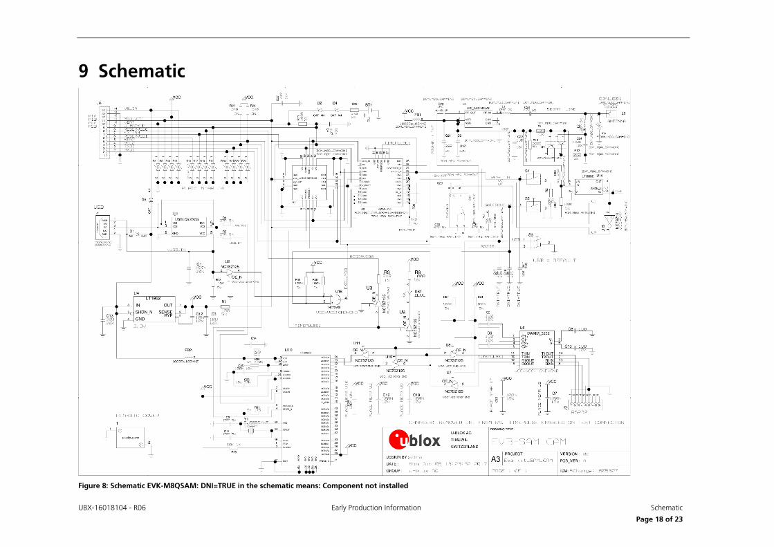
9 Schematic
Figure 8: Schematic EVK-M8QSAM: DNI=TRUE in the schematic means: Component not installed
UBX-16018104 - R06 Early Production Information Troubleshooting
Page 19 of 23
10 Troubleshooting My application (e.g. u-center) does not receive anything
Check whether the blue LED on the evaluation unit is blinking. Also make sure that the USB cable is properly connected to the evaluation unit and the PC. By default, the evaluation unit outputs NMEA protocol on Serial
Port 1 at 9600 Bd, or on the USB.
My application (e.g. u-center) does not receive all messages
When using UART, make sure the baud rate is sufficient. If the baud rate is insufficient, GNSS receivers based on
u-blox M8 GNSS technology will skip excessive messages. Some serial port cards/adapters (i.e. USB to RS232
converter) frequently generate errors. If a communication error occurs while u-center receives a message, the message will be discarded.
My application (e.g. u-center) loses the connection to the GNSS receiver
u-blox M8 positioning technology and u-center have an autobauding feature. If frequent communication errors occur (e.g. due to problems with the serial port), the connection may be lost. This happens because u-center
and the GNSS receiver both autonomously try to adjust the baud rate. Do not enable the u-center autobauding
feature if the GNSS receiver has the autobauding flag enabled.
The COM port does not send any messages
Be sure that the slide switch at the front side is set to RS232 and not USB. In USB Mode the RS232 pins on the
DB9 connector are switched off.
Some COM ports are not shown in the port list of my application (e.g. u-center)
Only the COM ports that are available on your computer will show up in the COM port drop down list. If a COM
Port is gray, another application running on this computer is using it.
After installing USB driver for the first time by connecting EVK-M8QSAM to PC with USB cable, the
cursor on PC starts to jump around the screen
The syndrome is caused when the NMEA 0183 GNSS serial data is misinterpreted as a mouse data by the serial port enumerator (serenum.sys), resulting in erratic mouse cursor activity. Change the USB/RS232 switch to
RS232 can help to recover the control of the cursor and disable the enumerator setting in the Windows Device
Manager / Ports (COM&LPT) / USB Serial Port (COMxx) / Port Settings / Advanced...
The position is off by a few dozen meters
u-blox M8 GNSS technology starts up with the WGS84 standard GNSS datum. If your application expects a
different datum, you’ll most likely find the positions to be off by a few dozen meters. Don’t forget to check the calibration of u-center map files.
The position is off by hundreds of meters
Position drift may also occur when almanac navigation is enabled. The satellite orbit information retrieved from an almanac is much less accurate than the information retrieved from the ephemeris. With an almanac only
solution, the position will only have an accuracy of a few kilometers but it may start up faster or still navigate in
areas with obscured visibility when the ephemeris from one or several satellites have not yet been received. The almanac information is NOT used for calculating a position, if valid ephemeris information is present, regardless
of the setting of this flag.
In NMEA protocol, position solutions with high deviation (e.g. due to enabling almanac navigation) can be filtered with the Position Accuracy Mask. UBX protocol does not directly support this since it provides a position
accuracy estimation, which allows the user to filter the position according to his requirements. However, the
“Position within Limits” flag of the UBX-NAV-STATUS message indicates whether the configured thresholds (i.e. P Accuracy Mask and PDOP) are exceeded.
TTFF times at startup are much longer than specified
At startup (after the first position fix), the GNSS receiver performs an RTC calibration to have an accurate internal time source. A calibrated RTC is required to achieve minimal startup time.
EVK-M8QSAM - User Guide
UBX-16018104 - R06 Early Production Information Troubleshooting
Page 20 of 23
Before shutting down the receiver externally, check the status in MON-HW in field “Real Time Clock Status”. Do not shut down the receiver if the RTC is not calibrated.
The EVK-M8QSAM does not meet the TTFF specification
Make sure the antenna has a good sky view. An obstructed view leads to prolonged startup times. In a well-designed system, the average of the C/No ratio of high elevation satellites should be in the range of 40 dBHz to
about 50 dBHz. With a standard off-the-shelf active antenna, 47 dBHz should easily be achieved. Low C/No
values lead to a prolonged startup time.
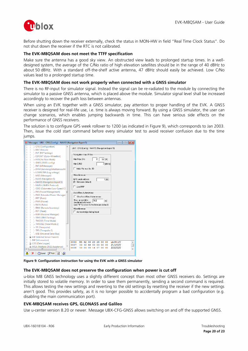
The EVK-M8QSAM does not work properly when connected with a GNSS simulator
There is no RF-input for simulator signal. Instead the signal can be re-radiated to the module by connecting the
simulator to a passive GNSS antenna, which is placed above the module. Simulator signal level shall be increased accordingly to recover the path loss between antennas.
When using an EVK together with a GNSS simulator, pay attention to proper handling of the EVK. A GNSS
receiver is designed for real-life use, i.e. time is always moving forward. By using a GNSS simulator, the user can change scenarios, which enables jumping backwards in time. This can have serious side effects on the
performance of GNSS receivers.
The solution is to configure GPS week rollover to 1200 (as indicated in Figure 9), which corresponds to Jan 2003. Then, issue the cold start command before every simulator test to avoid receiver confusion due to the time
jumps.
Figure 9: Configuration instruction for using the EVK with a GNSS simulator
The EVK-M8QSAM does not preserve the configuration when power is cut off
u-blox M8 GNSS technology uses a slightly different concept than most other GNSS receivers do. Settings are
initially stored to volatile memory. In order to save them permanently, sending a second command is required. This allows testing the new settings and reverting to the old settings by resetting the receiver if the new settings
aren’t good. This provides safety, as it is no longer possible to accidentally program a bad configuration (e.g.
disabling the main communication port).
EVK-M8QSAM receives GPS, GLONASS and Galileo
Use u-center version 8.20 or newer. Message UBX-CFG-GNSS allows switching on and off the supported GNSS.
EVK-M8QSAM - User Guide
UBX-16018104 - R06 Early Production Information Common evaluation pitfalls
Page 21 of 23
11 Common evaluation pitfalls A parameter may have the same name but a different definition. GNSS receivers may have a similar size,
price and power consumption but can still have different functionalities (e.g. no support for passive antennas, different temperature range). Also, the definitions of hot, warm, cold start times may differ
between suppliers.
Verify design-critical parameters; do not base a decision on unconfirmed numbers from datasheets.
Try to use identical or at least similar settings when comparing the GNSS performance of different receivers.
Data that has not been recorded at the same time and the same place should not be compared. The satellite constellation, the number of visible satellites, and the sky view might have been different.
Do not compare momentary measurements. GNSS is a non-deterministic system. The satellite constellation
changes constantly. Atmospheric effects (i.e. dawn and dusk) have an impact on signal travel time. The position of the GNSS receiver is typically not the same between two tests. Comparative tests should
therefore be conducted in parallel by using one antenna and a signal splitter; statistical tests shall be run for
24 hours.
Monitor the Carrier-To-Noise-Ratio. The average C/No ratio of the high elevation satellites should be
between 40 dBHz and about 50 dBHz. A low C/No ratio will result in a prolonged TTFF and more position
drift.
When comparing receivers side by side, make sure that all receivers have the same signal levels. The best
way to achieve this is by using a signal splitter. Comparing results measured with different antenna types
(with different sensitivity) will lead to incorrect conclusions.
Try to feed the same signal to all receivers in parallel (i.e. through a splitter); the receivers won’t have the
same sky view otherwise. Even small differences can have an impact on the accuracy. One additional satellite can lead to a lower DOP and less position drift.
EVK-M8QSAM - User Guide
UBX-16018104 - R06 Early Production Information Related documents
Page 22 of 23
Related documents [1] SAM-M8Q Data Sheet, Docu. No. UBX-16012619
[2] SAM-M8Q Hardware Integration Manual, Docu. No. UBX-16018358
[3] u-blox 8 / u-blox M8 Receiver Description including Protocol Specification, Docu. No. UBX-13003221
(Public Release)
[4] u-center – User Guide, Docu. No. UBX-13005250
[5] Information technology equipment – Safety Standard IEC 60950-1
https://webstore.iec.ch/publication/4024
For regular updates to u-blox documentation and to receive product change notifications, register on our
homepage.
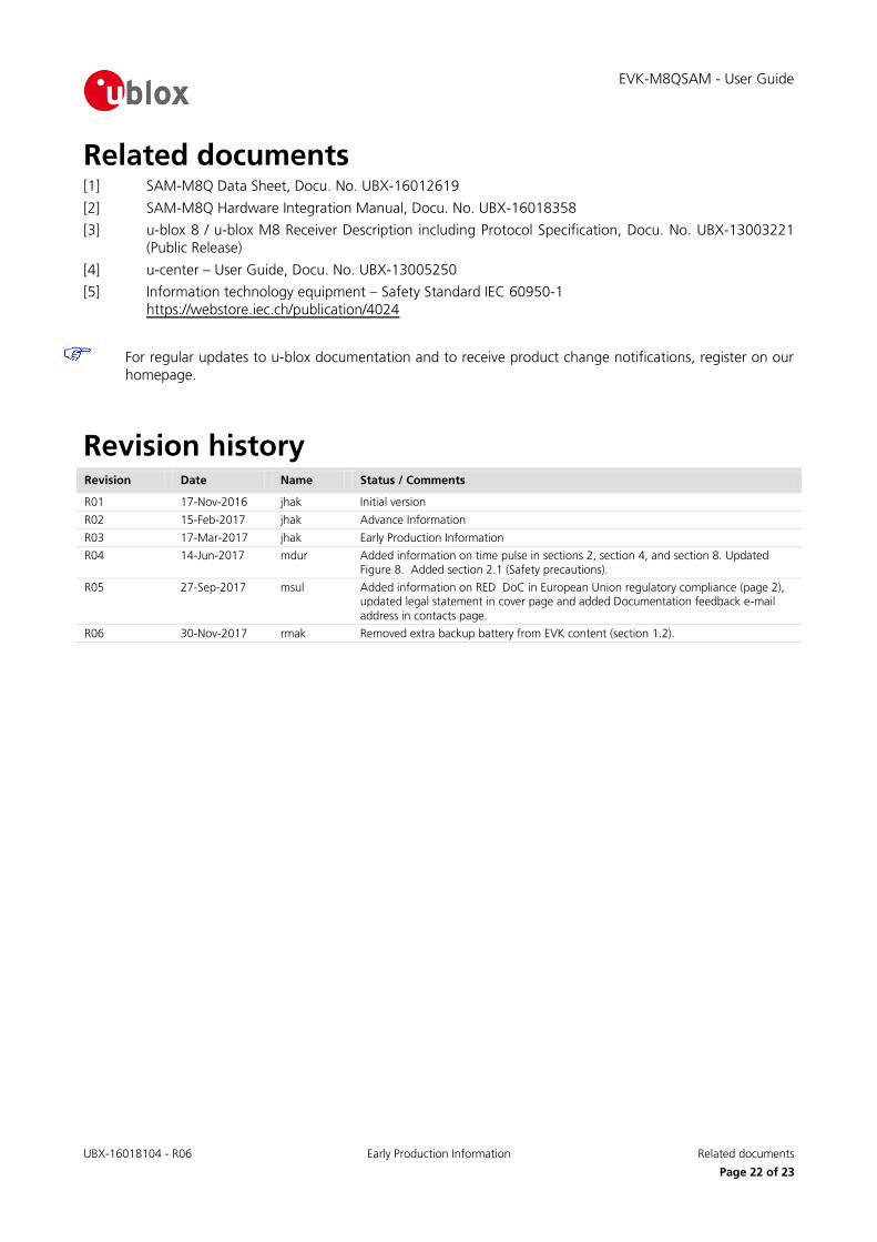
Revision history Revision Date Name Status / Comments
R01 17-Nov-2016 jhak Initial version
R02 15-Feb-2017 jhak Advance Information
R03 17-Mar-2017 jhak Early Production Information
R04 14-Jun-2017 mdur Added information on time pulse in sections 2, section 4, and section 8. Updated Figure 8. Added section 2.1 (Safety precautions).
R05 27-Sep-2017 msul Added information on RED DoC in European Union regulatory compliance (page 2), updated legal statement in cover page and added Documentation feedback e-mail
address in contacts page.
R06 30-Nov-2017 rmak Removed extra backup battery from EVK content (section 1.2).
EVK-M8QSAM - User Guide
UBX-16018104 - R06 Early Production Information Contact
Page 23 of 23
Contact For complete contact information visit us at www.u-blox.com
u-blox Offices
North, Central and South America
u-blox America, Inc.
Phone: +1 703 483 3180
E-mail: [email protected]
Regional Office West Coast:
Phone: +1 408 573 3640
E-mail: [email protected]
Technical Support:
Phone: +1 703 483 3185
E-mail: [email protected]
Headquarters Europe, Middle East, Africa
u-blox AG
Phone: +41 44 722 74 44 E-mail: [email protected]
Support: [email protected]
Documentation Feedback
E-mail: [email protected]
Asia, Australia, Pacific
u-blox Singapore Pte. Ltd.
Phone: +65 6734 3811
E-mail: [email protected] Support: [email protected]
Regional Office Australia:
Phone: +61 2 8448 2016 E-mail: [email protected]
Support: [email protected]
Regional Office China (Beijing):
Phone: +86 10 68 133 545 E-mail: [email protected]
Support: [email protected]
Regional Office China (Chongqing):
Phone: +86 23 6815 1588
E-mail: [email protected]
Support: [email protected]
Regional Office China (Shanghai):
Phone: +86 21 6090 4832
E-mail: [email protected]
Support: [email protected]
Regional Office China (Shenzhen):
Phone: +86 755 8627 1083
E-mail: [email protected] Support: [email protected]
Regional Office India:
Phone: +91 80 4050 9200 E-mail: [email protected]
Support: [email protected]
Regional Office Japan (Osaka):
Phone: +81 6 6941 3660 E-mail: [email protected]
Support: [email protected]
Regional Office Japan (Tokyo):
Phone: +81 3 5775 3850
E-mail: [email protected]
Support: [email protected]
Regional Office Korea:
Phone: +82 2 542 0861
E-mail: [email protected] Support: [email protected]
Regional Office Taiwan:
Phone: +886 2 2657 1090 E-mail: [email protected]
Support: [email protected]