Embed Size (px)
Citation preview

evohome Installation Guide
The connected heating controller
Quick Actions Living room Kitchen Bedroom 2
~ 22° 17.5° 12° if ii: Ii e,
Hot Water Dining room Bedroom 1 Bathroom
47° 15° 19° 23° • II· ti ~p<lmlsa<loo :(): SETTINGS flll SCHEDULE < . >
Honeywell

evohome Controller
Digital Room Thermostat (DTS92)
Wireless Relay Box (BDR91)
Wireless Relay Box (BDR91)
Wireless Cylinder Thermostat Transceiver (CS92)
Wireless Cylinder Thermostat Strap-on Sensor (CS92)
Wireless Cylinder Thermostat Insertion Sensor (CS92)
Radiator Controller (HR92)
Radiator Controller (HR80)
Wireless OpenTherm Bridge (R8810)
Mixing Valve Controller (HM80)
Underfloor Heating Controller (HCE80 or HCC80)
evohome Controller Wall Bracket (ATF600)
evohome Controller Table Stand (ATF800)
Room Temperature Sensor (HCW82)
Single Zone Thermostat (Y87RF)
Room Temperature Sensor (HCF82)
Ho
t W
ater
Kit
(AT
F500
DH
W)
Icon key
@ @ @ @ @) @ @ @ @ @--"""'T"'""""""I
@ (!) @ Q)
e @ __ ............... @

1evohome Installation Guide
Thanks for choosing evohomeevohome means more comfort, and more control of the heating system. It’s simple to install and easy to use.
Follow these instructions to set up the evohome system. Devices that need to be connected to the mains electricity supply should be installed by a competent person.
Before you startMake sure you have all the devices you need for your system. If you used our ‘Design your evohome system’ guide, match each device to the room or zones in your plan. It’s a good idea to carry out all the mains electrical and other wiring work first.
In this guideStep 1: Wire up the heating system 3Step 2: Set up your evohome Controller 9Step 3: Power up and bind devices 13Step 4: System test 29Configuration and modification 37Appendix 41
2 Step 1: Wire up the heating system
Step 2: Set up your evohome ControllerPower up the evohome Controller, connect to a WiFi network and follow the on-screen instructions for your system
Go to Installer Menu Go to Guided Configuration Go to Home screen
You have…a Connected Pack +Un-bound devices
You have…an un-bound evohome Controller+Un-bound devices
You have…a Connected Pack+No additional devices
Step 3: Power up and bind devicesPower up all devices, including the battery powered ones, and bind them to the evohome Controller
Step 1: Wire up your heating systemConnect all mains powered devices to the heating system
Step 4: Test the systemCheck that all the devices are working properly
- - -- - -• • • - - -- - -• • •
@ © @ - - -- - -• • ----------- - -- - -• • •

3evohome Installation Guide
In this sectionWireless Relay Box (BDR91) 4Wireless Cylinder Thermostat (CS92) 5Mixing Valve Controller (HM80), Underfloor Heating Controller (HCE80/HCC80), Opentherm Bridge (R8810) 7
Step 1: Wire up the heating systemevohome communicates using wireless on a robust 868Mhz signal that is unaffected by common remote controls or WiFi.
Some devices need mains power or to be connected to external equipment and it's best to wire up these items first to simplify the binding process later in the setup. The evohome controller will give on screen instructions when these should be powered up.
Before you power up your evohome Controller and install the radiator controllers, it's best to install any devices which are mains powered or need specific installation.

4 Step 1: Wire up the heating system
Turn off at mains and isolate the supply before starting
!If you’re fitting a Wireless Relay Box (BDR91) to your boiler, zone valve or Sundial valve1 Mount the Wireless Relay Box on a non-
metal surface at least 30cm from your boiler, other wireless devices or metal objects
2 Release the clip on the bottom to open the front cover
3 Follow the wiring diagram (see Appendix: Figures 5-10) to connect the Wireless Relay Box to your boiler’s thermostat terminals, zone valve or sundial valve, and to the mains electricity supply
4 Replace the cover
Refer to boiler instruction to locate the room thermostat terminals, determine if the boiler required a permanent live supply.
Wireless Relay Box (BDR91)
1
4
BOILER
MINIMUM 30CM
REPLACE FRONT COVER
@ • • • •
•
•
. ........... .
I ffi

5evohome Installation Guide
If you’re fitting a Wireless Cylinder Thermostat (CS92)You will need to install the CS92 Transceiver and only one of the two sensors (CS92 Strap-on Sensor or CS92 Insertion Sensor).
To fit the CS92 Strap-on Sensor
1 Cut away a section of cylinder insulation slightly larger than the sensor unit
2 Clean the exposed cylinder surface
3 Place the sensor on the cylinder surface and secure it using the fixing strap – cut the strap to size if it’s too long
4 Install the CS92 Transceiver in a suitable location close enough for the cable from the sensor to reach
5 Connect the cable from the sensor to the CS92 Transceiver
Position the sensor from one quarter to a third of the way up the cylinder.
Wire to CS92 Transceiver
Wireless Cylinder Thermostat (CS92)
1 3
1/4 – 1/3 TOTAL HEIGHT
45MM
80MM
MINIMUM 30CM
A x B Cy
A x B Cy
5
@
•
• • • •
. ......

6 Step 1: Wire up the heating system
Wireless Cylinder Thermostat (CS92) continued
To fit the CS92 Insertion Sensor
1 Fit in the cylinder immersion well with suitable fittings to provide strain relief and prevent accidental removal
2 If the sensor doesn’t fit tightly in the immersion well fill the space with heat-conductive compound to ensure maximum heat transfer
3 Install the CS92 Transceiver in a suitable location close enough for the cable from the sensor to reach
4 Connect the cable from the sensor to the CS92 Transceiver.
The wires are polarity free, so can be connected in any order. Provide appropriate strain relief to this end of the sensor cable as well.
If this sensor is used in an unvented hot water storage application, the cylinder manufacturer’s instructions must be followed to ensure compliance with all safety regulations.
If in doubt, contact the cylinder manufacturer.
!
4
Wire to CS92 Transceiver
A x B Cy
A x B Cy
Q) • • • •
•
• • .(' .(' .(' .(' .('
•••••

7evohome Installation Guide
If you’re fitting a Mixing Valve Controller (HM80), Underfloor Heating Controller (HCE80/HCC80), OpenTherm Bridge (R8810)Refer to the installation instructions supplied with each device
Mixing Valve Controller (HM80), Underfloor Heating Controller (HCE80/HCC80), OpenTherm Bridge (R8810)
@ 8 @
8 Step 1: Wire up the heating system

9evohome Installation Guide
Step 2: Set up your evohome ControllerThe evohome Controller has a guided configuration process to help you set up the zones for a single type of system. For mixed systems (i.e. Under Floor Heating zones plus Radiator zones) use Guided Configuration for the larger system then “Add Zones” in the installer menu.
To add a stored hot water system use the guided configuration Stored Hot Water option in the installer menu.
The following instructions cover the full configuring process for a zone, but if you are using Guided Configuration your evohome Controller will give you on-screen instructions to bind the other components to the evohome Controller – just follow the bind instruction for each device in this manual.
In this sectionPowering up your evohome Controller 10Language selection and WiFi configuration 11Set-up the evohome controller for your system 12

10 Step 2: Set up your Central Controller
First, power up the evohome Controller
1 Remove the cover, remove the battery tab and replace the cover.
2 Place it on the table stand or wall bracket
3 Once the batteries are fully charged, the evohome Controller can be easily removed from the table stand or wall bracket for ease of programming. After 30 minutes the evohome Controller will emit a beep to indicate that it should be replaced on the stand or wall bracket
Your evohome Controller comes with *rechargeable batteries which are pre-charged allowing you to set-up the system while off the table stand or wall bracket.
Place the evohome Controller on the table stand or wall bracket for normal use.
*Only use the AA rechargeable batteries provided.
!
1
Powering up your evohome Controller
PULL TAB
• • •
• --•

11evohome Installation Guide
Select a language for the evohome controller and connect to a WiFi network1 Select a language for the evohome controller user interface
2 Follow the on-screen instructions to connect to a WiFi network. This enables automatic setting of the date and time for your location, as well as enabling remote connectivity via an Apple or Android Smartphone.
• To configure WiFi you will need the home WiFi network password
3 Instruct the homowner / user to visit www.mytotalconnectcomfort.com to create an account, register the evohome Controller and download the app.
• To create an account and register the evohome Controller the homeowner will need the MAC ID and CRC which can be found:
– On a label behind the front cover of the evohome Controller
– on screen during the WiFi set-up
– in the SETTINGS > WiFi SETTINGS menu after set-up has been completed
If you don't have the WiFi network details, or the homeowner doesn't require remote access you can skip the WiFi configuration and proceed with setting up the heating system.
WiFi can be configured later in the SETTINGS > WIFI SETTINGS menu.
!
Language selection and WiFi configuration
Select your store Get the App
• •
• •
, Available on the
App Store
GET IT ON
~ Google play
MAGID
CRC
} Honeywell

12 Step 2: Set up your Central Controller
Now choose the correct option for the system you’re installing:
For a Connected Pack* and NO additional un-bound devices we recommended pressing ‘Home’ – then go to "Step 4: System test" on page 29.
For a Connected Pack*, PLUS additional un-bound devices we recommended pressing ‘Installation Menu’ to add the un-bound devices and follow "Step 3: Power up and bind devices" on page 13.
For an un-bound evohome Controller, PLUS additional un-bound devices we recommended pressing ‘Guided Configuration’ to add the un-bound devices and follow "Step 3: Power up and bind devices" on page 13.
* A Connected Pack contains devices which are already bound to the evohome Controller. Choosing "Guided Configuration" will delete the binding from evohome Controller and will require to be bound again. The Wireless Relay Box (BDR91) in a Connected Pack is bound as a boiler controller. If you intend to use it as a Zone Valve or S-Plan/Y-Plan (Sundial) Valve controller the binding must be cleared from the Wireless Relay Box first.
Set-up the evohome controller for your system
@
@
©

13evohome Installation Guide
Step 3: Power up and bind devicesIf you bought a Connected Pack only — your devices are already bound. Go to Step 4.
If you bought an unbound evohome Controller, plus other un-bound devices and are using ‘Guided Configuration’ follow the instructions on your evohome Controller screen and use this section to put the devices into binding mode.
If you bought a Connected Pack, plus other un-bound devices, you need to power up all devices and then bind them to the evohome Controller using the ‘Installation Menu’. It may be easier to power up and bind some devices while they’re close to the evohome Controller – you can install them in their assigned zones later.
Follow the instructions for the device(s) you’re going to bind. When you bind a device to the evohome Controller the devices permanently store the connection and there should never be a need to rebind them again – even after a power cut.
In this sectionRadiator Controllers (HR92) 14Wireless Cylinder Thermostat (CS92) 16Wireless Relay Box (BDR91) to control a Boiler 18OpenTherm Bridge (R8810) 19Wireless Relay Box (BDR91) to control a Zone Valve 20Radiator Controller (HR80) 22Underfloor Heating Controller (HCE80 or HCC80) 24Mixing Valve Controller (HM80) 27

14 Step 3: Power up and bind devices
Power up and bind Radiator Controllers (HR92) – Your evohome Zone Kit
Bind the Radiator Controllers (HR92)
1 Remove the circular top cover
2 Open the battery clip and insert the AA batteries supplied
3 Close the clip and replace the cover
4 Press the button once − it should say UNBOUND
5 Press and hold the button for a further 5 seconds until it says BIND
6 Press the button once – it should say BINDING
7 You should receive a SUCCESS message on the evohome Controller (if not go back and re-bind)
8 The name of the allocated zone should appear on the HR92 display when you press the button
9 Either press the green tick to add another radiator to the zone. Or press the red cross if you don’t need to add another radiator to the zone
If you are NOT following GUIDED CONFIGURATION follow these steps on your evohome Controller display first:
1. Press and hold ‘Settings’ for 3 seconds
2. Press the green tick
3. Press ADD ZONE
4. Type a name for the new zone and press the green tick
5. Press RADIATOR VALVE
6. If you want to control the zone temperature with the evohome Controller (which needs to be located in that zone) press YES, otherwise press NO.
You must repeat these steps for each radiator controller.
evohome Controller
Radiator Controllers (HR92)
1 2 4 5 6
PRESS ONCE
PRESS AND HOLD
5 SEC
PRESS ONCE
• @
• • • • Bil •
• • • •
~ -
~ -
~ -
r:3 1:3
IEII

15evohome Installation Guide
Install the Radiator Controllers (HR92)
1 Locate the room (zone) for the radiator controller
2 Slide the locking mechanism to the unlock position
3 Remove the adaptor from the bottom of the controller
4 Unscrew the black wheel fully anti-clockwise
5 Remove any existing control on the radiator valve
6 Screw the white end of the adaptor on to the radiator valve
7 Push the controller fully on to the adaptor with the screen facing towards you
8 Slide the locking mechanism to the locked position
REMOVE
ROTATE2
3
3 4
7
@ • • • • • • • •
lllllllllljlllllllllll
~
• ·cc 1111 1111111 111111 11111
~'''""'~ ;§ ~ ~ - . ,::-, ~ .
l =
t

16 Step 3: Power up and bind devices
Power up and bind the CS92 Transceiver
On the CS92 Transceiver
1 Remove the CS92 Transceiver cover, pull out the battery tab and replace the cover
2 On the CS92 Transceiver press and hold the button for 5 seconds. The green light should come on and the red light should flash
3 Press the button again
4 You should receive a SUCCESS message on the evohome Controller (if not go back and re-bind)
5 Choose the correct hot water valve type for the system you’re installing and follow the on screen instructions
To control a stored hot water system you first need to bind the CS92 Transceiver and then bind the Wireless Relay Box (BDR91) that is controlling the hot water valve.
If you are NOT following GUIDED CONFIGURATION follow these steps on your evohome Controller display first:
1. Press and hold “Settings” for 3 seconds
2. Press the green tick
3. Select GUIDED CONFIGURATION
4. Press STORED HOT WATER CONFIGURATION
5. Press the green tick
evohome Controller
Wireless Cylinder Thermostat (CS92)
PRESS ONCE
1
PULL TAB
PRESSAND HOLD 5 SEC
2
@ • • • • • •
•
~''"'~ . -
I;! - ..
: ~/JI\\~
•
..... ··:
. .... l ··: ~

17evohome Installation Guide
To bind the Wireless Relay Box (BDR91) controlling the hot water valve1 On the Wireless Relay Box, press and hold the
button for 15 seconds (until the red LED blinks rapidly) to clear any previous binding data
2 Press and hold the button again for 5 seconds (until the red LED blinks slowly)
3 On the evohome Controller press the green bind button
4 You should receive a SUCCESS message on the evohome Controller (if not go back and re-bind)
You may need to refer to the wiring diagrams in the Appendix
!
The Wireless Relay Box in a Connected Pack is bound as a boiler controller. If you intend to use it as a S-Plan/Y-Plan Valve controller the binding must be cleared from the Wireless Relay Box first – as described in step 1.
!1 2
PRESSAND HOLD 15 SEC
PRESSAND HOLD 5 SEC
@ • • • • • •

18 Step 3: Power up and bind devices
Power up and bind a Wireless Relay Box (BDR91) to control a boiler Make sure the Wireless Relay Box (BDR91) is wired to the boiler and powered up.
To bind the Relay Box
1 Press and hold the button for 15 seconds (until the red LED blinks rapidly) to clear any previous binding data
2 Press and hold the button again for 5 seconds (until the red LED blinks slowly)
3 On the evohome Controller press the green bind button
4 You should receive a SUCCESS message on the evohome Controller (if not go back and re-bind)
If you are NOT following GUIDED CONFIGURATION follow these steps on your evohome Controller display first:
1. Press and hold ‘Settings’ for 3 seconds
2. Press the green tick
3. Press SYSTEM DEVICES
4. Press BOILER CONTROL
5. Press BOILER RELAY
evohome Controller
Wireless Relay Box (BDR91) to control a boiler
1 2
PRESSAND HOLD 15 SEC
PRESSAND HOLD 5 SEC
• @
• • • • • •

19evohome Installation Guide
Power up and bind an OpenTherm Bridge (R8810) to control an OpenTherm boiler Make sure the OpenTherm Bridge (R8810) is wired to the boiler and powered up.
To bind the OpenTherm Bridge
1 Press and hold the button for 15 seconds (until the red LED blinks rapidly) to clear any previous binding data
2 Press and hold the button again for 5 seconds (until the red LED blinks slowly)
3 On the evohome Controller press the green bind button
4 You should receive a SUCCESS message on the evohome Controller (if not go back and re-bind)
If you are NOT following GUIDED CONFIGURATION follow these steps on your evohome Controller display first:
1. Press and hold ‘Settings’ for 3 seconds
2. Press the green tick
3. Press SYSTEM DEVICES
4. Press BOILER CONTROL
5. Press OPENTHERM BRIDGE
evohome Controller
OpenTherm Bridge (R8810)
1 2
PRESSAND HOLD 15 SEC
PRESSAND HOLD 5 SEC
@
• • • • • •

20 Step 3: Power up and bind devices
Power up and bind a Wireless Relay Box (BDR91) to control a Zone ValveMake sure the Wireless Relay Box (BDR91) is wired to the Zone Valve and powered up.
If you want to control the zone temperature with the evohome Controller (the evohome Controller needs to be located in that zone) press YES, otherwise press NO and bind a sensor – either Digital Room Thermostat (DTS92), Single Zone Thermostat (Y87RF), or Room Temperature Sensor (HCW82/HCF82).
To bind the Digital Room Thermostat (DTS92)
1 Press and hold the power button for 2 seconds to put the unit into standby
2 Press the up and down arrows together for 3 seconds – it should say INst
3 Press the down arrow – it should say COnt
4 Press the up arrow three times – it should say CLr
5 Press the power button once to clear any previous binding data
6 Press the up arrow – it should say COnt
7 Press the power button once to send the binding signal to the evohome Controller
8 You should receive a SUCCESS message on the evohome Controller (if not go back and re-bind)
To bind the Single Zone Thermostat (Y87RF)
1 Press and hold on the left touch zone (just below and to the left of the display) for approximately 10 seconds until a flashing 'Bo' is displayed
2 Turn the dial clockwise until a flashing 'Co' is displayed
3 Press the left touch zone once to send the binding signal to the evohome Controller
4 You should receive a SUCCESS message on the evohome Controller (if not go back and re-bind)
If you are NOT following GUIDED CONFIGURATION follow these steps on your evohome Controller display first:
1. Press and hold “Settings” for 3 seconds
2. Press the green tick
3. Press ADD ZONE
4. Type a name for the new zone and press the green tick
5. Press ZONE VALVES
evohome Controller
All of the remote room sensors will automatically exit from their binding menu after a short period.
!
Wireless Relay Box (BDR91) to control a Zone Valve
• @
@ • • • • • • • •
@ • • • •

21evohome Installation Guide
To bind the Room Temperature Sensor (HCW82 or HCF82)1 Press the bind button on the bottom right hand corner
of the unit once. The red LED light will flash
2 You should receive a SUCCESS message on the evohome Controller (if not go back and re-bind)
Then, on the Wireless Relay Box (BDR91)
1 Press and hold the button for 15 seconds (until the red LED blinks rapidly) to clear any previous binding data
2 Press and hold the button again for 5 seconds (until the red LED blinks slowly)
3 On the evohome Controller press the green bind button
4 You should receive a SUCCESS message on the evohome Controller (if not go back and re-bind)
The Wireless Relay Box in a Connected Pack is bound as a boiler controller. If you intend to use it as a Zone Valve controller the binding must be cleared from the Wireless Relay Box first.
!
1
1 2
PRESSAND HOLD 15 SEC
PRESSAND HOLD 5 SEC
@ •
@ • •
• • • • •
--
•
,., -•-,,,
-
~0

22 Step 3: Power up and bind devices
Power up and bind a Radiator Controller (HR80)If you want to control the zone temperature with your evohome Controller (the evohome Controller needs to be located in that zone) press YES, otherwise press NO and bind the sensor.
On the HR80, you need to bind the sensor and actuator separately1 Power up the Radiator Controller (see HR80 instructions)
To bind the sensor
2 Turn release clips on each side of the Radiator Controller to remove the bottom plate
3 On the underside of the Radiator Controller press the recessed bind button
4 The Radiator Controller screen should briefly show a flashing RF icon then SYNC when successful. The evohome Controller will also show if binding was successful (if not go back and re-bind)
If you are NOT following GUIDED CONFIGURATION follow these steps on your evohome Controller display first:
1. Press and hold “Settings” for 3 seconds
2. Press the green tick
3. Press ADD ZONE
4. Type a name for the new zone and press the green tick
5. Press RADIATOR VALVE
evohome Controller
Radiator Controller (HR80)
2 3SIDE VIEW BOTTOM VIEW
• • • •
• •

23evohome Installation Guide
To bind the actuator
5 Press the bind button on the Radiator Controller (if there are multiple HR80’s in the zone, do this to all of them). The screen should show a flashing RF icon
6 On the evohome Controller press the green bind button
7 Check that (all) the Radiator Controllers display SYNC. If a Radiator Controller does not display SYNC and the flashing RF icon remains, press back on the evohome Controller and press the green bind button again
8 Press the next arrow on the evohome Controller
5 BOTTOM VIEW
• • • • •

24 Step 3: Power up and bind devices
Power up and bind an Underfloor Heating Controller (HCE80 or HCC80)If you want to control the zone temperature with your evohome Controller (the evohome Controller needs to be located in that zone) press YES, otherwise press NO and bind a sensor – either Digital Room Thermostat (DTS92), Single Zone Thermostat (Y87RF), or Room Temperature Sensor (HCW82/HCF82)
To bind the Digital Room Thermostat (DTS92)
1 Press and hold the power button for 2 seconds to put the unit into standby
2 Press the up and down arrows together for three seconds – it should say INst
3 Press the down arrow – it should say COnt
4 Press the up arrow three times – it should say CLr
5 Press the once to clear any previous binding data
6 Press the up arrow – it should say COnt
7 Press the once to send the binding signal to the evohome Controller
8 You should receive a SUCCESS message on the evohome Controller (if not go back and re-bind)
To bind the Single Zone Thermostat (Y87RF)
1 Press and hold on the left touch zone (just below and to the left of the display) for approximately 10 seconds until a flashing 'Bo' is displayed
2 Turn the dial clockwise until a flashing 'Co' is displayed
3 Press the left touch zone once to send the binding signal to the evohome Controller
4 You should receive a SUCCESS message on the evohome Controller (if not go back and re-bind)
Make sure the zone you’re adding on the evohome Controller corresponds to the correct underfloor heating zone.
!
If you are NOT following GUIDED CONFIGURATION follow these steps on your evohome Controller display once the underfloor heating controller and sensors have been fitted:
1. On the evohome Controller press and hold “Settings” for 3 seconds
2. Press the green tick
3. Press ADD ZONE
4. Type a name for the new zone and press the green tick
5. Press UNDERFLOOR HEATING
6. You need to install a sensor (HCW82, HCF82, DTS92) in each zone controlled by the underfloor heating controller and bind it to the evohome Controller.
You need to repeat this process for every zone that uses underfloor heating.
evohome Controller
Underfloor Heating Controller (HCE80 or HCC80)
• 8
@. C!)
• • • • C!)
• • C!)
•
@ • • • •

25evohome Installation Guide
To bind the Room Temperature Sensor (HCW82 or HCF82)1 Press the bind button on the bottom right hand corner
of the unit once. The red LED light will flash
2 You should receive a SUCCESS message on the evohome Controller (if not go back and re-bind)
CONTINUED ON NEXT PAGE
1
All of the remote room sensors will automatically exit from their binding menu after a short period.
! @ •
@ • • ,,, -·-,,,
-- . -
~

26 Step 3: Power up and bind devices
Then on the underfloor controller
1 Press and hold the bind button until the bind light turns solid YELLOW and the zone number light flashes (either GREEN or RED).
Follow the instructions below depending on which colour the zone number light is flashing:
If the zone light is flashing GREEN (single stage bind):
2 On the evohome Controller, press the green bind button
3 When the zone light turns solid YELLOW the binding is successful for the zone
4 Press forward on the evohome Controller to complete the binding for this zone
If you are binding more zones repeat the process from the sensor binding step on the previous page, then press the bind button twice on the Underfloor Heating Controller - The GREEN light will flash on the next zone.
If the zone light is flashing RED (two stage bind):
2 On the evohome Controller, press the green bind button
3 When the message is received the zone light will turn solid RED
4 Press the back arrow on the evohome Controller
5 Press the bind button on the Underfloor Heating Controller – the zone light should flash GREEN
6 On the evohome Controller, press the green bind button
7 When the zone light turns solid GREEN the binding is successful for the zone
8 Press forward on the evohome Controller to complete the binding for this zone
If you are binding more zones repeat the process from the sensor binding step on the previous page, then press the bind button once on the Underfloor Heating Controller - The RED light will flash on the next zone.
There are two versions of HCE80/HCC80, newer versions have a simplified single stage bind process while older versions have a two stage bind process.
Note the colour of the flashing zone light (GREEN or RED) and follow the instructions for that version. Put a tick next to the version for future reference.
!
Underfloor Heating Controller (HCE80 or HCC80) continued
e . 0....___ ______ _
0
• • •
• • • • • •
~
~
'I

27evohome Installation Guide
Power up and bind a Mixing Valve Controller (HM80)A Mixing Valve Controller should only be fitted by a qualified fitter. Unless you’re using the evohome Controller as a sensor, you need to install a sensor (DTS92, Y87RF, HCW82 or HCF82) before binding the controller to the evohome Controller.
To bind the Digital Room Thermostat (DTS92)
1 Press and hold the power button for 2 seconds to put the unit into standby
2 Press the up and down arrows together for three seconds – it should say INst
3 Press the down arrow – it should say COnt
4 Press the up arrow three times – it should say CLr
5 Press the power button once to clear any previous binding data
6 Press the up arrow – it should say COnt
7 Press the power button once to send the binding signal to the evohome Controller
8 You should receive a SUCCESS message on the evohome Controller (if not go back and re-bind)
To bind the Single Zone Thermostat (Y87RF)
1 Press and hold on the left touch zone (just below and to the left of the display) for approximately 10 seconds until a flashing 'Bo' is displayed
2 Turn the dial clockwise until a flashing 'Co' is displayed
3 Press the left touch zone once to send the binding signal to the evohome Controller
4 You should receive a SUCCESS message on the evohome Controller (if not go back and re-bind)
If you are NOT following GUIDED CONFIGURATION follow these steps on your evohome Controller display once the Mixing Valve Controller and sensor have been installed:
1. On the evohome Controller press and hold “Settings” for 3 seconds
2. Press the green tick
3. Press ADD ZONE
4. Type a name for the new zone and press the green tick
5. Press MIXING VALVE
6. If you want to control the zone temperature with your evohome Controller (the evohome Controller needs to be located in that zone) YES, otherwise press NO and bind the sensor.
evohome Controller
Mixing Valve Controller (HM80)
All of the remote room sensors will automatically exit from their binding menu after a short period.
!
CONTINUED ON NEXT PAGE
• @
@ • • - • • • • • •
@ • • • •

28 Step 3: Power up and bind devices
To bind the Room Temperature Sensor (HCW82 or HCF82)1 Press the bind button on the bottom right hand corner
of the unit once. The red LED light will flash
2 You should receive a SUCCESS message on the evohome Controller (if not go back and re-bind)
Then on the Mixing Valve Controller
1 Press and hold both buttons on the Mixing Valve Controller for 4 seconds until the red light flashes
2 On the evohome Controller press the green bind button
3 Press the next arrow on the evohome ControllerStill want to control the Boiler?
A Mixing Valve Controller will not provide a heat demand to the boiler.
If you do want this zone to provide a heat demand simply change the heating type from 'MIXING VALVE' to 'ZONE VALVES' once the Mixing Valve controller is bound.
There's no need to re-bind any device – The Mixing Valve Controller will still operate as intended and the evohome Controller will send the heat demand to the boiler.
!
Mixing Valve Controller (HM80) continued
1
PRESSAND HOLD 4 SEC
1
@ •
@ • •
• • • •
-- A

29evohome Installation Guide
Step 4: System testNow that all the devices are bound to your evohome Controller and installed in their final locations, check that the system works properly and that all the devices are responding to commands from the evohome Controller.
You can perform a simple functional check of the heating system by overriding the temperature of each zone to their minimum and maximum while listening for a response from the radiator (or zone) controllers and boiler. To save power the battery devices only communicate with the evohome Controller every four minutes therefore the system may not respond immediately to a manual temperature change.
In this sectionAdvanced RF communication check 30
Mains Powered Wireless Devices 30Battery Powered Wireless Devices 31

30 Step 4: System test
To check the RF signal strength between the wireless devices and the evohome Controller go to RF COMMS CHECK in the evohome Controller Installer Menu and test each wireless device.
1 On the evohome Controller press and hold ‘Settings’ for 3 seconds
2 Press the green tick
3 Press RF COMMS CHECK
4 Choose the devices you want to test
Mains Powered Wireless DevicesMains powered devices do not need to be put into test mode and will automatically respond to the test message sent from the evohome Controller:
Wireless Relay Box (BDR91)
• The Relay Box will flash the red LED from 1 flash (poor) to 5 flashes (excellent) – no flashing means the Relay Box has not received a test signal from the evohome Controller
Underfloor Heating Controller (HCE80/HCC80)
• The Underfloor Heating Controller will flash the green LED for the zone you are testing from 1 flash (poor) to 5 flashes (excellent) – no flashing means the Underfloor Heating Controller has not received a test signal from the evohome Controller
To save power the battery devices only communicate with the evohome Controller every four minutes therefore the system may not respond immediately to a manual change.
!
Advanced RF communication check
@
8
• • • •

31evohome Installation Guide
Battery Powered Wireless DevicesBattery powered devices need to be put into test mode to send and receive a test signal:
Radiator Controller (HR92)
1 Press the button, the zone name is displayed
2 Press and hold the button again for 5 seconds, the display should say BIND
3 Turn the dial to display RF CHECK
4 Press the button, the display should flash CHECKING
5 Press the button again, the display should flash SIGNAL and will display a signal strength bar and a rating from 1 (poor) to 5 (excellent) – 0 means the Radiator Controller has not received a test signal from the evohome Controller.
6 To exit test mode turn the dial to exit and press the button. It will also exit automatically after 10 minutes.
1 2 3 4
PRESSAND HOLD 4 SEC
"RF CHECK"
@ • ~ -
• ~ -
• • ~ -
• ~ -
• •

32 Step 4: System test
Radiator Controller (HR80)
1 Separate the Radiator Controller from the adaptor on the radiator
2 Turn the adjustment dial clockwise (approx two full rotations) until TEST is displayed
The evohome Controller will display the signal strength (poor to excellent) – nothing on the evohome Controller display means the Radiator Controller has not received a test signal from the evohome Controller.
3 To exit test mode remove and reinsert the batteries from the Controller. It will exit automatically after 5 minutes.
Advanced RF communication check continued
2
@ • •
• •
I

33evohome Installation Guide
Digital Room Thermostat (DTS92)
1 Put the Room Thermostat into standby mode
2 Press up and down together for 3 seconds
3 Press down once, the display should say CONT
4 Press down for 3 seconds, the display should say TEST
5 Press down for 3 seconds, the display should say SS
The evohome Controller will display the signal strength (poor to excellent) and the Room Thermostat will display a signal strength rating from 1 (poor) to 5 (excellent) – 0 means the Room Thermostat has not received a test signal from the evohome Controller.
6 To exit test mode, press off on Room Thermostat for 5 seconds. It will exit automatically after 10 minutes.
2
PRESSAND HOLD 3 SEC
1
PRESSAND HOLD 2 SEC
@ • • • • •
• •
•
o 11111
6 _. 111111111ll111 1
11111111111111

34 Step 4: System test
Room Temperature Sensor (HCF82 or HCW82)
1 Remove the cover from the sensor
2 Press and hold the bind button for approximately 30 seconds until the red LED goes off
3 The red LED will flash each time it sends a test message
The evohome Controller will display the signal strength (poor to excellent) – no flashing means the Temperature Sensor has not received a test signal from the evohome Controller.
4 To exit test mode, press the bind button on the Temperature Sensor. It will exit automatically after 5 minutes.
Advanced RF communication check continued
1 2
PRESSAND HOLD 30 SEC
@. @: • • • ,1, -•-,,,
-- .

35evohome Installation Guide
Wireless Cylinder Thermostat (CS92A)
1 Press the button on the Cylinder Thermostat transceiver for 5 seconds
2 The green light should come on. If it doesn’t, reinsert the batteries and try again
The evohome Controller will display the signal strength (poor to excellent) and the transceiver should flash the red LED from 1 flash (poor) to 5 flashes (excellent) – no flashing means the transceiver has not received a test signal from the evohome Controller.
4 To exit test mode press the button on the transceiver.
1
PRESSAND HOLD 5 SEC
@ • •
• •

36 Step 4: System test

37evohome Installation Guide
Configuration and modificationOnce you’ve completed these steps you’re ready to start using your evohome system. You can also make parameter adjustments in the evohome Controller to match the exact requirements of the heating system. The operation and functions of the each zone can also be adjusted. These can be found in the Installer Menu.
Components can be added or replaced by editing the zones or system in the Installer menu.
In this sectionParameters and control features 38Configuring a zone with multiple rooms 38Adding or replacing components in an existing system 39

38 Configuration and modification
evohome allows you to create a zone with multiple rooms (i.e. Bedroom's) that are controlled together as one group. It does this by letting all the radiator controllers bound to that zone to independently measure room temperature and control a radiator. This means you can locate the radiator controllers in separate rooms without them all being controlled by one temperature sensor like a single room zone does.
To create a multiple room zone either:
• Add a new zone and bind the radiator controllers for all the rooms. Go to the parameters menu and select multiple room zone.
or
• Go to Zone Configuration and edit an existing zone's parameters. Any bound radiator controllers already bound to that zone will now work independently
Once you’ve completed these steps you’re ready to start using evo. The user guide gives you instructions for personalising the settings on the evohome Controller.
You can also make parameter adjustments on your evohome Controller to match the exact requirements of the heating system. These can be found in the Installer Menu.
1 On the evohome Controller press and hold ‘Settings’ for 3 seconds
2 Press the green tick
3 Press SYETEM PARAMETERS and choose the parameter you want to adjust:
– Internal Sensor Offset – Cycle Rate – Minimum On Time – Fail Safe – Hot Water Parameters
For more details on parameters visit www.evohome.honeywell.com
A multiple room zone does not support separate remote temperature sensors (such as DTS92).
Room temperature sensing is done by the radiator controllers.
!
Parameters and control features
Configuring a zone with multiple rooms
• • •
39evohome Installation Guide
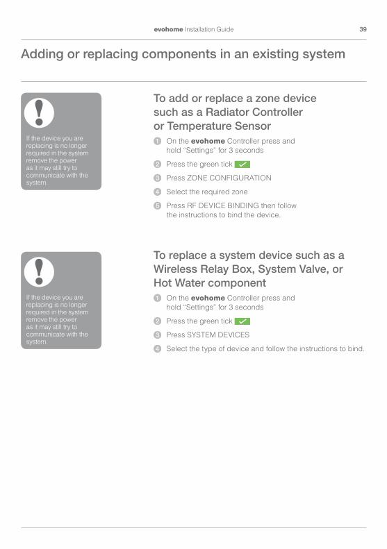
To add or replace a zone device such as a Radiator Controller or Temperature Sensor1 On the evohome Controller press and
hold “Settings” for 3 seconds
2 Press the green tick
3 Press ZONE CONFIGURATION
4 Select the required zone
5 Press RF DEVICE BINDING then follow the instructions to bind the device.
To replace a system device such as a Wireless Relay Box, System Valve, or Hot Water component1 On the evohome Controller press and
hold “Settings” for 3 seconds
2 Press the green tick
3 Press SYSTEM DEVICES
4 Select the type of device and follow the instructions to bind.
If the device you are replacing is no longer required in the system remove the power as it may still try to communicate with the system.
!
If the device you are replacing is no longer required in the system remove the power as it may still try to communicate with the system.
!
Adding or replacing components in an existing system
• • • • •
• • • •

40 Configuration and modification

41evohome Installation Guide
AppendixHeating system schematics, Wiring diagrams
In this sectionSample evohome systems 42Wiring diagrams 44Safety information 48evohome Controller technical data 49

42 Appendix
Single zoneThe evohome Controller is the sensor for the whole home which is controlled to the same time and temperature schedule.
This system also includes wireless connectivity, which is available for any configuration.
Honeywell S plan 2 two-port valvesThere are two zone valves − one for stored hot water one for central heating. The evohome Controller is the sensor for the whole home which is controlled to the same time and temperature schedule. The valves open when needed. The boiler is operated via a wired junction box.
If a system has been set up and the Wireless Relay Boxes are moved to a new function, the relay binding must be cleared or it will continue to carry out its original function.
!
Figure 1 Single zone system
Figure 2 Honeywell S plan
Sample evohome systems
Pump
DHW Heating
Radiators
DHW Cylinder
BOILER
JunctionBox
V4043 V4043
BDR91Wireless
Relay Box
BDR91WirelessRelay Box
evohomeCentral Controller
CS92AWirelessCylinder
Thermostat
BOILER
Radiators
Pump
evohomeCentral Controller
RFG100Remote Access
Gateway
BDR91Wireless
Relay Box D ~~~ 1-----===-L
I>)]
.,f D 000 h------==:=-L

43evohome Installation Guide
Honeywell Y plan 1 three-port mid-position valveThe operation is identical to the S plan but it uses a single three-port or mid position valve.
Stored hot water and zoned heating
If a system has been set up and the Wireless Relay Boxes are moved to a new function, the relay binding must be cleared or it will continue to carry out its original function.
!
If a system has been set up and the Wireless Relay Boxes are moved to a new function, the relay binding must be cleared or it will continue to carry out its original function.
!
Figure 3 Honeywell Y plan
Figure 4 Stored hot water and zoned heating system. This system needs HR92s or other zoning solutions for the radiators.
Pump
Radiators
DHW Cylinder
BOILER
JunctionBox
V4073evohomeCentral Controller
DHW HeatingBDR91
WirelessRelay Box
BDR91WirelessRelay Box
CS92AWirelessCylinder
Thermostat
Pump
Radiators
DHW Cylinder
BOILER
JunctionBox
V4043evohomeCentral Controller
DHWBDR91
WirelessRelay Box
CS92AWirelessCylinder
Thermostat
HR92RadiatorController
BDR91WirelessRelay Box

44 Appendix
Connecting a Wireless Relay Box to a:
Basic boiler
Boiler that requires a permanent live For use with boiler that require a permanent live (this is a typical Combi boiler wiring) but please check manufacturers instructions. This can be used for boilers with low voltage or 230vac room thermostat inputs.
Figure 5 Wiring for a basic boiler (not requiring a pump overrun). The relay powers the boiler live input.
Figure 6 Boiler that requires a permanent live
Boiler room thermostat terminals (see instructions). Remove link at boiler if fitted. If the boiler has an inbuilt timer leave this on constant.
Wiring diagrams
230V50-60Hz
<5AN L
N L
L
BDR91
Place link here
A-B:5(3)AA-C:5(3)A
A B C
L
N
230V50-60Hz
<5AN L L
BDR91 A-B:5(3)AA-C:5(3)A
A B C
LN
N L
-
-

45evohome Installation Guide
Two-port zone valveFigure 7 Connecting a two port zone valveG/Y: Green/Yellow Earth wireBL: Blue Motor NeutralBR: Brown Motor LiveGR: Grey End switch (if
used) Permanent LiveO: Orange End switch (If
used). In wired system this typically feeds the boiler. When a wireless relay box is fitted the end switch is not required.
Connecting an Opentherm bridge
Figure 8 Wiring an OpenTherm Bridge to an OpenTherm boiler.
If connecting a two port zone valve with an unvented cylinder connection for a high limit thermostat, the 'L' permanent live feed must be broken when high limit cutout activates on the insertion thermostat.
!
230V50-60Hz
<5AN L L
BDR91
V4043H
A-B:5(3)AA-C:5(3)A
A B C
LN
BL BRM
GR OG/Y
Opentherm input on the boiler ONLY.Do not connect to the room thermostat terminals
Opentherm bridge
Opentherm equipped boiler-• OpenTherm•

46 Appendix
Sundial or system valves
S Plan: 2 two-port valves with a wired boiler
Figure 9 Two port valves with a wired boiler. If a wireless boiler relay is used the Grey, Orange wire and feed to pump and boiler are not required.
Wiring diagrams continued
230V50Hz
3A RATED
V4043HZONE VALVE
HTG
BLUE
G/YELLOW
G/YE
LLOW
GREY
GREY
BLUE
BROW
N
BROW
N
ORAN
GE
ORAN
GE
N
N
BOILER
E
E
LL
MOTORMOTOR
PUMP
V4043HZONE VALVE
HW
L N E
1 2 3 4 5 6 7 8 9 10
HTG DHW
N A BL
RECEIVERBDR91
N A BL
RECEIVERBDR91

47evohome Installation Guide
Y Plan: Three-port Mid position valve with a wired boilerIf a wireless boiler relay is used the Orange wire and feed to pump and boiler are not required.
Figure 10 Mid position (3 port) valveG/Yellow: Earth wireBLUE: Motor NeutralWHITE: Heating relayGREY: Hot water relayORANGE: End switch (If used). In wired system this typically feeds the boiler. When a wireless boiler relay is fitted the end switch is not required.
N E LPUMP
HTG
N A BL
RECEIVERBDR91
DHW
N A BL
CRECEIVERBDR91
1 2 3 4 5 6 7 8 9 10
230V50Hz
3A RATED
L N E
N
BOILER
EL
V4073AMID POSITIONZONE VALVEBL
UE
G/YE
LLOW
WHI
TE
GREY
ORAN
GE

48 Appendix
ApprovalsConforms to protection requirements of the following directives:EMC: 2004/108/ECLVD: 2006/95/ECR&TTE: 1999/05/ECHereby, Honeywell, declares that this evohome Controller is in compliance with the essential requirements and other relevant provisions of Directive 1999/5/EC.
EMC compliance considerations
Refer to Code of Practice standards EN61000-5-1 and -2 for guidance.
Caution: Isolate power supply and make safe before wiring the unit to prevent electric shock and equipment damage. Installation should be carried out by a competent person.
Location of device
evohome Controller should be installed in an open space for best performance as it is a radio frequency device. Leave at least 30cm distance from any metal objects including wall boxes and at least 1 metre from any other electrical equipment eg. radio, TV, PC etc. Do not mount onto metal wall boxes.
For the best temperature control performance the evohome Controller should not be placed near heat or cool sources (e.g. cooker, lamp, radiator, doorways, windows).
Disclaimer
This product and its associated documentation and packaging are protected by various intellectual property rights belonging to Honeywell Inc and its subsidiaries and existing under the laws of the UK and other countries. These intellectual and property rights may include patent applications, registered designs, unregistered designs, registered trademarks, unregistered trademarks and copyrights.
Honeywell reserves the right to modify this document, product and functionality without notice. This document replaces any previously issued instructions and is only applicable to the product(s) described.
This product has been designed for applications as described within this document. For use outside of the scope as described herein, refer to Honeywell for guidance. Honeywell cannot be held responsible for misapplication of the product(s) described within this document.
PLEASE RESPECT YOUR ENVIRONMENT!
Take care to dispose of this product and any packaging or literature in an appropriate way.
WEEE directive 2012/19/EU
Waste Electrical and Electronic Equipment directive
• At the end of the product life dispose of the packaging and product in a corresponding recycling centre.
• Do not dispose of the unit with the usual domestic refuse.
• Do not burn the product.
• Remove the batteries.
• Dispose of the batteries according to the local statutory requirements and not with the usual domestic refuse.
Safety information
~ -

49evohome Installation Guide
evohome Controller technical data
Electrical
Table Stand Power supply
Input voltage: 100-240V 50/60Hz 0.2A
Output voltage: +5V 1A
Wall Bracket Power supply
Input voltage: 230VAC ±10%
Output voltage: 4VDC ±0.2V, max 2.6W
Room unit power supply input
5V ±0.2V, max. 2.6W
Low voltage cable length (max)
10m, 1.0mm2; 5m, 0.5mm2
Battery type (rechargeable)
Type AA 1.2V NiMH 2000-2400mAh
RF Communication
RF operation band ISM (868.0—870.0) MHz, RX Class 2
RF communication range
30m in a residential building environment
Wireless LAN IEEE 802.11b,g,n (2.400-2.485 GHz)
Environmental and Standards
Operating temperature 0 to 40ºC
Storage temperature -20 to +50°C
Humidity 10 to 90% relative humidity non condensing
IP Protection Class lP30
Mechanical
Dimensions 136 x 93 x 20mm (WxHxD)
evohome
evohome is designed to convert a system with single zone pipework into a multi zone system, resulting in optimal control and comfort combined with maximum energy saving.
For more information on Smart Heat Zoning for your home, visit:
www.evohome.honeywell.com
Honeywell Control Systems Ltd.Skimped Hill Lane,BracknellBerkshireRG12 1EBwww.honeywelluk.com
32303494-001 A
© 2014 Honeywell International Inc.
Manufactured for and on behalf of the Environmental and Combustion Controls Division of Honeywell Technologies Sàrl, ACS-ECC EMEA, Z.A. La Pièce 16, 1180 Rolle, Switzerland by its Authorised Representative Honeywell Inc.
Honeywell

Check out our full range of Heating Products
Central Heating Controls
Honeywell Heating Controls
Danfoss Heating Controls
Radiator Valves
Fernox
Sentinel
Magnaclean
Warmup underfloor heating
Water Heaters
Hand Dryers