Embed Size (px)
Citation preview
Evolution of the 4th Generation Mobile Communication Network: LTE-
Advanced
Khondokar Fida Hasan Md. Morshedul Islam
Lecturer, Department of Information and Communication Technology
Department of Computer Science and Engineering
Comilla University, Comilla, Bangladesh
Bangladesh University of Engineering and Technology (BUET), Dhaka, Bangladesh
E-Mail: [email protected] E-Mail: [email protected]
ABSTRACT
Mobile communication network experiences
dramatic advances and changes over the last two
decades. With the growing demand, the development of
the design and optimization of radio access technologies
and a further evolution of the existing system, the Third
Generation Partnership Project (3GPP) had laid down
the foundation of the future Long Term Evolution (LTE)
advanced standards as the 3GPP candidates for 4G. This
research work provides a high-level technical overview
of LTE Release-10, also known as LTE-Advanced. This
article covers a quick overview of LTE-Advanced
technology and its predecessor technologies. It also
describes all the technological enhancements introduced
to LTE-Advanced. Thus, this paper can steer all those
learners and researchers who desire to have a
foundation for further research and study in the field of
next generation mobile communication system.
Keywords: LTE, LTE-Advanced, 4G network, Carrier
Aggregation, Relaying, Spectrum Utilization.
I. INTRODUCTION
In recent years, the demand for mobile internet
access has grown significantly. The number of pages
viewed on the mobile Web browser Opera grew from 1.8
billion pages in January 2008 to 51.5 billion pages in
February 2011 where 7.3 petabytes of operator data were
compressed for 89.8 million Opera Mini users [1].
Nevertheless, the current technology is not widely
successful to serve and to satisfy the users because of its
low transmission rate and high service costs.
Consequently, research is going and new concepts toward
evolution are subjected to verify for implementation
throughout the world. Based on the requirements of high
speed mobile wireless access services, wireless systems
can be broadly classified as into two groups; Cellular
system based on IMT 2000 (WCDMA, HSDPA, HSUPA,
HSPA+, LTE/LTE-Advanced by 3GPP, CDMA2000 1X)
and Extension of fixed wireless systems incorporate
mobile functions i.e. WiMAX (IEEE 802.16e) & IEEE
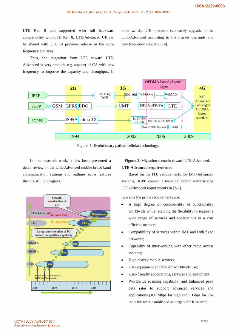
802.16m. The overall evolution of cellular technology is
diagrammatically shown in Figure-1[2]. LTE Advanced
is a broadband mobile communication standard. It is
being standardized by the 3rd Generation Partnership
Project (3GPP) as a major enhancement of the pre-4G
3GPP Long Term Evolution (LTE) standard, which
verified to be insufficient to satisfy market’s demand [3].
The 3GPP group has been working on different aspects to
improve LTE performance, using for this purpose the
framework provided by LTE Advanced, which includes
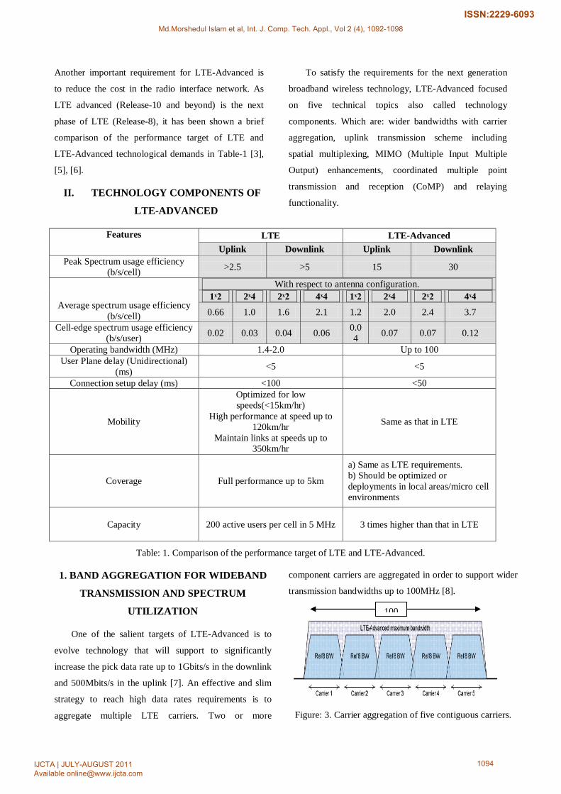
some advanced features. Figure 2 shows a typical
migration scenario toward LTE-Advanced. The
horizontal axis explains the performance which includes
capacity, throughput, latency and cost, etc. LTE
(Release-8) area will be overlaid firstly with
3G area and expanded gradually according to the
customer’s demand. Since LTE-Advanced is based on the
Md.Morshedul Islam et al, Int. J. Comp. Tech. Appl., Vol 2 (4), 1092-1098
IJCTA | JULY-AUGUST 2011 Available [email protected]
1092
ISSN:2229-6093
2G 3G
4G
IMT-Advanced Converged OFDMA
based standard
1994 2002 2006 2009
IS95A cdma 1X 1x EV-DO IS 956 DO Rev A DO Rev B
Flash-OFDM Rev 0 &
UMB
GSM GPRS EDG
UMT
HSDPA HSUPA LTE
802.11 b/g WiFi
802.16d WiMAX-e WiMAX-m
3GPP2
3GPP
IEEE
OFDMA based physical layer
LTE Rel. 8 and supported with full backward
compatibility with LTE Rel. 8, LTE-Advanced UE can
be shared with LTE of previous release in the same
frequency and area
Thus, the migration from LTE toward LTE-
Advanced is very smooth, e.g. support of CA with new
frequency to improve the capacity and throughput. In
other words, LTE operators can easily upgrade to the
LTE-Advanced according to the market demands and
new frequency allocation [4].
Figure: 1. Evolutionary path of cellular technology.
In this research work, it has been presented a
detail review on the LTE-Advanced mobile broad band
communication systems and outlines some features
that are still in progress.
Figure: 2. Migration scenario toward LTE-Advanced.
LTE-Advanced requirements:
Based on the ITU requirements for IMT-Advanced
systems, 3GPP created a technical report summarizing
LTE-Advanced requirements in [3-5].
In wards the prime requirements are:
• A high degree of commonality of functionality
worldwide while retaining the flexibility to support a
wide range of services and applications in a cost
efficient manner;
• Compatibility of services within IMT and with fixed
networks;
• Capability of interworking with other radio access
systems;
• High quality mobile services;
• User equipment suitable for worldwide use;
• User-friendly applications, services and equipment;
• Worldwide roaming capability; and Enhanced peak
data rates to support advanced services and
applications (100 Mbps for high and 1 Gbps for low
mobility were established as targets for Research).
Md.Morshedul Islam et al, Int. J. Comp. Tech. Appl., Vol 2 (4), 1092-1098
IJCTA | JULY-AUGUST 2011 Available [email protected]
1093
ISSN:2229-6093
Another important requirement for LTE-Advanced is
to reduce the cost in the radio interface network. As
LTE advanced (Release-10 and beyond) is the next
phase of LTE (Release-8), it has been shown a brief
comparison of the performance target of LTE and
LTE-Advanced technological demands in Table-1 [3],
[5], [6].
II. TECHNOLOGY COMPONENTS OF
LTE-ADVANCED
To satisfy the requirements for the next generation
broadband wireless technology, LTE-Advanced focused
on five technical topics also called technology
components. Which are: wider bandwidths with carrier
aggregation, uplink transmission scheme including
spatial multiplexing, MIMO (Multiple Input Multiple
Output) enhancements, coordinated multiple point
transmission and reception (CoMP) and relaying
functionality.
Features LTE LTE-Advanced Uplink Downlink Uplink Downlink
Peak Spectrum usage efficiency (b/s/cell) >2.5 >5 15 30
Average spectrum usage efficiency (b/s/cell)
With respect to antenna configuration. 1ˣ2 2ˣ4 2ˣ2 4ˣ4 1ˣ2 2ˣ4 2ˣ2 4ˣ4
0.66 1.0 1.6 2.1 1.2 2.0 2.4 3.7 Cell-edge spectrum usage efficiency
(b/s/user) 0.02 0.03 0.04 0.06 0.04 0.07 0.07 0.12
Operating bandwidth (MHz) 1.4-2.0 Up to 100 User Plane delay (Unidirectional)
(ms) <5 <5
Connection setup delay (ms) <100 <50
Mobility
Optimized for low speeds(<15km/hr)
High performance at speed up to 120km/hr
Maintain links at speeds up to 350km/hr
Same as that in LTE
Coverage Full performance up to 5km
a) Same as LTE requirements. b) Should be optimized or deployments in local areas/micro cell environments
Capacity 200 active users per cell in 5 MHz 3 times higher than that in LTE
Table: 1. Comparison of the performance target of LTE and LTE-Advanced.
1. BAND AGGREGATION FOR WIDEBAND
TRANSMISSION AND SPECTRUM
UTILIZATION
One of the salient targets of LTE-Advanced is to
evolve technology that will support to significantly
increase the pick data rate up to 1Gbits/s in the downlink
and 500Mbits/s in the uplink [7]. An effective and slim
strategy to reach high data rates requirements is to
aggregate multiple LTE carriers. Two or more
component carriers are aggregated in order to support wider
transmission bandwidths up to 100MHz [8].
Figure: 3. Carrier aggregation of five contiguous carriers.
100
Md.Morshedul Islam et al, Int. J. Comp. Tech. Appl., Vol 2 (4), 1092-1098
IJCTA | JULY-AUGUST 2011 Available [email protected]
1094
ISSN:2229-6093
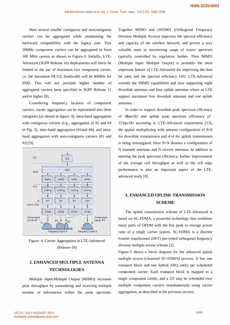
Here several smaller contiguous and noncontiguous
carriers can be aggregated while maintaining the
backward compatibility with the legacy user. Five
20MHz component carriers can be aggregated to form
100 MHz system as shown in Figure-3. Initially, LTE-
Advanced (3GPP Release 10) deployments will likely be
limited to the use of maximum two component carrier,
i.e. the maximum DL/UL bandwidth will be 40MHz for
FDD. This will not preclude higher number of
aggregated carriers been specified in 3GPP Release 11
and/or higher [8].
Considering frequency location of component
carriers, carrier aggregation can be represented into three
categories (as shown in figure: 4); intra-band aggregation
with contiguous carriers (e.g., aggregation of #2 and #3
in Fig. 2), inter-band aggregation (#1and #4), and intra-
band aggregation with non-contiguous carriers (#1 and
#2) [9].
Figure: 4. Carrier Aggregation in LTE-Advanced
(Release-10)
2. ENHANCED MULTIPLE ANTENNA
TECHNOLOGIES
Multiple Input/Multiple Output (MIMO) increases
peak throughput by transmitting and receiving multiple
streams of information within the same spectrum.
Together MIMO and OFDMA (Orthogonal Frequency
Division Multiple Access) improves the spectral efficiency
and capacity of the wireless network, and proves a very
valuable asset in maximizing usage of scarce spectrum
typically controlled by regulatory bodies. Thus MIMO
(Multiple Input Multiple Output) is probably the most
important feature of LTE-Advanced for improving the data
bit rates and the spectral efficiency [10]. LTE-Advanced
extends the MIMO capabilities and now supporting eight
downlink antennas and four uplink antennas where as LTE
support maximum four downlink antennas and one uplink
antennas.
In order to support downlink peak spectrum efficiency
of 30 bps/Hz and uplink peak spectrum efficiency of
15 bps/Hz according to LTE-Advanced requirement [13],
the spatial multiplexing with antenna configuration of 8×8
for downlink transmission and 4×4 for uplink transmission
is being investigated. Here N×N denotes a configuration of
N transmit antennas and N receive antennas. In addition to
meeting the peak spectrum efficiency, further improvement
of the average cell throughput as well as the cell edge
performance is also an important aspect of the LTE-
advanced study [8].
3. ENHANCED UPLINK TRANSMISSION
SCHEME
The uplink transmission scheme of LTE-Advanced is
based on SC-FDMA, a powerful technology that combines
many parts of OFDM with the low peak to average power
ratio of a single carrier system. SC-FDMA is a discrete
Fourier transformed (DFT) pre-coded orthogonal frequency
division multiple access scheme [3].
Figure-5 shows a block diagram for the enhanced uplink
multiple access (clustered SC-FDMA) process. It has one
transport block and one hybrid ARQ entity per scheduled
component carrier. Each transport block is mapped to a
single component carrier, and a UE may be scheduled over
multiple component carriers simultaneously using carrier
aggregation, as described in the previous section.
Md.Morshedul Islam et al, Int. J. Comp. Tech. Appl., Vol 2 (4), 1092-1098
IJCTA | JULY-AUGUST 2011 Available [email protected]
1095
ISSN:2229-6093
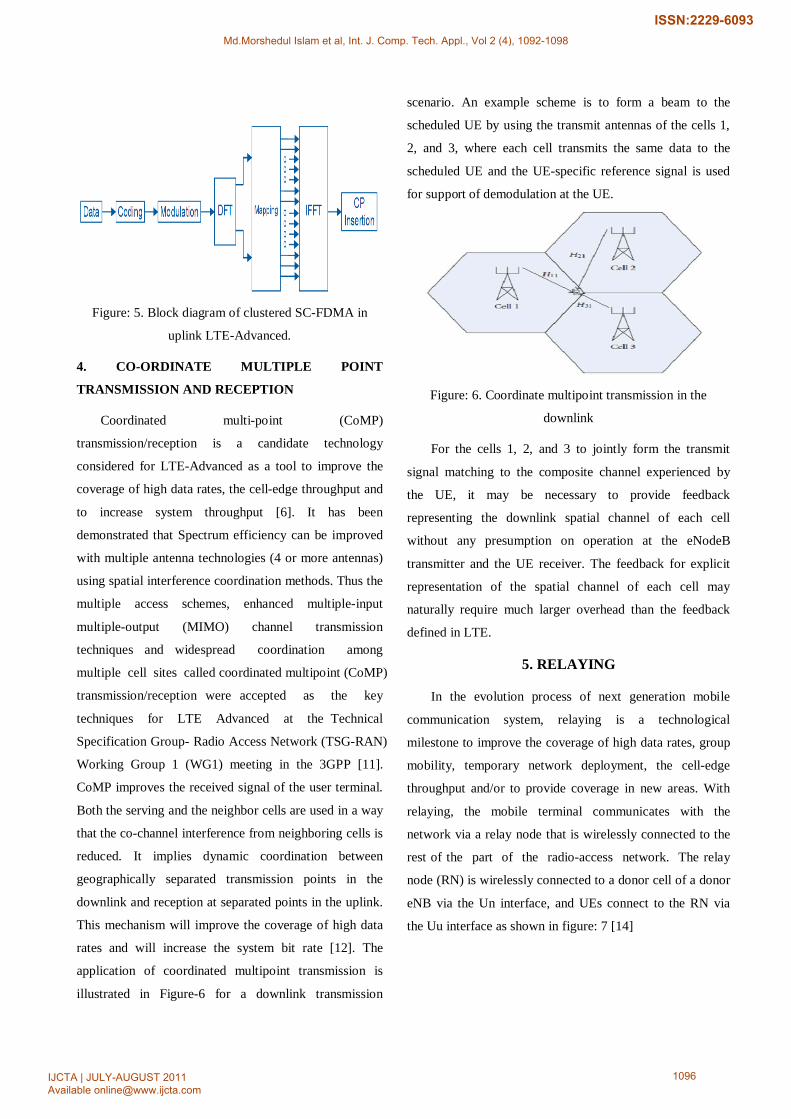
Figure: 5. Block diagram of clustered SC-FDMA in
uplink LTE-Advanced.
4. CO-ORDINATE MULTIPLE POINT
TRANSMISSION AND RECEPTION
Coordinated multi-point (CoMP)
transmission/reception is a candidate technology
considered for LTE-Advanced as a tool to improve the
coverage of high data rates, the cell-edge throughput and
to increase system throughput [6]. It has been
demonstrated that Spectrum efficiency can be improved
with multiple antenna technologies (4 or more antennas)
using spatial interference coordination methods. Thus the
multiple access schemes, enhanced multiple-input
multiple-output (MIMO) channel transmission
techniques and widespread coordination among
multiple cell sites called coordinated multipoint (CoMP)
transmission/reception were accepted as the key
techniques for LTE Advanced at the Technical
Specification Group- Radio Access Network (TSG-RAN)
Working Group 1 (WG1) meeting in the 3GPP [11].
CoMP improves the received signal of the user terminal.
Both the serving and the neighbor cells are used in a way
that the co-channel interference from neighboring cells is
reduced. It implies dynamic coordination between
geographically separated transmission points in the
downlink and reception at separated points in the uplink.
This mechanism will improve the coverage of high data
rates and will increase the system bit rate [12]. The
application of coordinated multipoint transmission is
illustrated in Figure-6 for a downlink transmission
scenario. An example scheme is to form a beam to the
scheduled UE by using the transmit antennas of the cells 1,
2, and 3, where each cell transmits the same data to the
scheduled UE and the UE-specific reference signal is used
for support of demodulation at the UE.
Figure: 6. Coordinate multipoint transmission in the
downlink
For the cells 1, 2, and 3 to jointly form the transmit
signal matching to the composite channel experienced by
the UE, it may be necessary to provide feedback
representing the downlink spatial channel of each cell
without any presumption on operation at the eNodeB
transmitter and the UE receiver. The feedback for explicit
representation of the spatial channel of each cell may
naturally require much larger overhead than the feedback
defined in LTE.
5. RELAYING
In the evolution process of next generation mobile
communication system, relaying is a technological
milestone to improve the coverage of high data rates, group
mobility, temporary network deployment, the cell-edge
throughput and/or to provide coverage in new areas. With
relaying, the mobile terminal communicates with the
network via a relay node that is wirelessly connected to the
rest of the part of the radio-access network. The relay
node (RN) is wirelessly connected to a donor cell of a donor
eNB via the Un interface, and UEs connect to the RN via
the Uu interface as shown in figure: 7 [14]
Md.Morshedul Islam et al, Int. J. Comp. Tech. Appl., Vol 2 (4), 1092-1098
IJCTA | JULY-AUGUST 2011 Available [email protected]
1096
ISSN:2229-6093
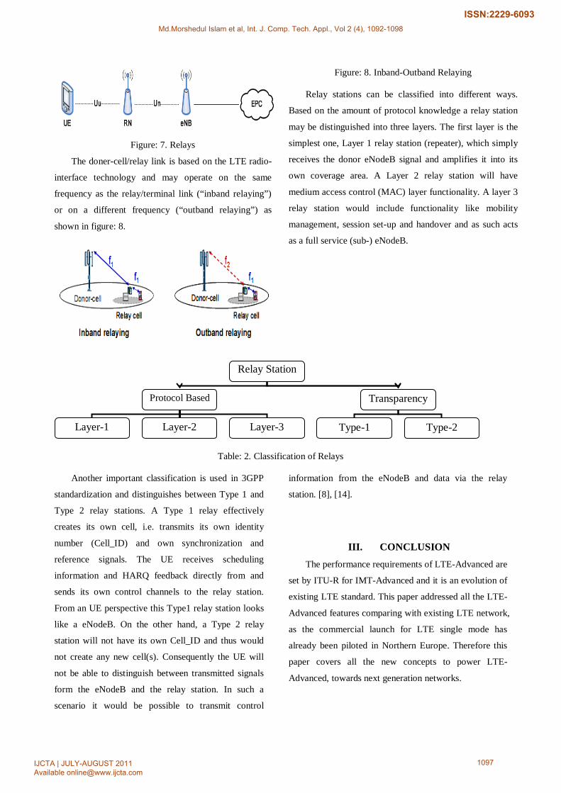
Figure: 7. Relays
The doner-cell/relay link is based on the LTE radio-
interface technology and may operate on the same
frequency as the relay/terminal link (“inband relaying”)
or on a different frequency (“outband relaying”) as
shown in figure: 8.
Figure: 8. Inband-Outband Relaying
Relay stations can be classified into different ways.
Based on the amount of protocol knowledge a relay station
may be distinguished into three layers. The first layer is the
simplest one, Layer 1 relay station (repeater), which simply
receives the donor eNodeB signal and amplifies it into its
own coverage area. A Layer 2 relay station will have
medium access control (MAC) layer functionality. A layer 3
relay station would include functionality like mobility
management, session set-up and handover and as such acts
as a full service (sub-) eNodeB.
Table: 2. Classification of Relays
Another important classification is used in 3GPP
standardization and distinguishes between Type 1 and
Type 2 relay stations. A Type 1 relay effectively
creates its own cell, i.e. transmits its own identity
number (Cell_ID) and own synchronization and
reference signals. The UE receives scheduling
information and HARQ feedback directly from and
sends its own control channels to the relay station.
From an UE perspective this Type1 relay station looks
like a eNodeB. On the other hand, a Type 2 relay
station will not have its own Cell_ID and thus would
not create any new cell(s). Consequently the UE will
not be able to distinguish between transmitted signals
form the eNodeB and the relay station. In such a
scenario it would be possible to transmit control
information from the eNodeB and data via the relay
station. [8], [14].
III. CONCLUSION The performance requirements of LTE-Advanced are
set by ITU-R for IMT-Advanced and it is an evolution of
existing LTE standard. This paper addressed all the LTE-
Advanced features comparing with existing LTE network,
as the commercial launch for LTE single mode has
already been piloted in Northern Europe. Therefore this
paper covers all the new concepts to power LTE-
Advanced, towards next generation networks.
Relay Station
Protocol Based Transparency
Layer-1 Layer-2 Layer-3 Type-1 Type-2
Md.Morshedul Islam et al, Int. J. Comp. Tech. Appl., Vol 2 (4), 1092-1098
IJCTA | JULY-AUGUST 2011 Available [email protected]
1097
ISSN:2229-6093
REFERENCE [1] “State of the Mobile Web, February 2011.” Opera
tech report,
<http://www.opera.com/smw/2011/02/>
[2]. Matti Kiiski, “LTE-Advanced: The Mainstream in
Mobile Broadband Evolution.” European Wireless
Conference, Nokia Siemens Networks Oulu,
Finland, 2010.
[3]. “Introducing LTE advanced”, An application note
by Agilent Technologies.
[4]. S. Abeta, “Towards LTE Commercial Launch and
Future Plan for LTE Enhancements (LTE-
Advanced), NTT DOCOMO, INC. IEEE, 2010
[5]. Jolly Parikh, Anuradha Basau, “LTE Advanced:
The 4G Mobile Broadband Technology”
International Journal of Computer Applications
(0975-8887), Volume 13- No. 5, 2011.
[6]. A. Kumar, Y. Liu, A. Wason,, “LTE-Advanced:
The Roadmap to 4G mobile wireless networks.”
Global journal of Computer Science and
Technolgy, vol. 10 no. 4, Ver. 1.0, pp. 50-53, 2010.
[7]. D.M.Sacristan, Jose F.Monserrat. J.Penuelas, et al,
“On the way towards forth-generation mobile:
3GPP, LTE and LTE-Advanced.” EURASIP
Journal on Wireless Communications and
Networking, 2009.
[8]. “LTE-Advanced Technology Introduction” Rohde &
Schwarz GmbH & Co. KG Mühldorfstraße 15 | D -
81671 München www.rohde-schwarz.com
[9]. S. Parkvall, A. Furuskar, et al., “Evolution of LTE
toward IMT-Advanced.” IEEE Communication
Magazine, 2011.
[10]. Juho Lee, Jin-Kyu Han, and Jianzhong (Charlie)
Zhang, “MIMO Technologies in 3GPP LTE and
LTE-Advanced.” EURASIP Journal on Wireless
Communications and Networking, Volume 2009
(2009), Article ID 302092.
[11]. 3GPP TR 36.814, V9.0.0, 2010, “Further
Advancements for E-UTRA Physical Layer
Aspects.” 2010.
[12]. LTE-Advanced, Release-10, www.3gpp.org, last
visited: 24th June 2011.
[13]. 3GPP, TR 36.913, “Requirements for Further
Advancements for E-UTRA (LTE-Advanced)
(Release 8)”.
[14]. Technical Specification Group Radio Access
network; Feasibility study for futher advancements
for E-UTRA(LTE-Advanced), Release 9; 3GPP TR
36.912V9.1.0,2009
Md.Morshedul Islam et al, Int. J. Comp. Tech. Appl., Vol 2 (4), 1092-1098
IJCTA | JULY-AUGUST 2011 Available [email protected]
1098
ISSN:2229-6093