Embed Size (px)
Citation preview

1ItpwJotgpot(ltc
twmslFsttu
fise
1994 J. Opt. Soc. Am. A/Vol. 25, No. 8 /August 2008 César Daniel Perciante
Evolution of the polarization state in materialmedia with uniform linear birefringence and an
applied nonhomogeneous external magneticfield: application to bulk-type Faraday current
sensors
César Daniel Perciante
Departamento de Ingeniería Eléctrica, Universidad Católica del Uruguay, Av. Ocho de Octubre 2738, Montevideo,Uruguay
Received August 13, 2007; revised June 2, 2008; accepted June 4, 2008;posted June 12, 2008 (Doc. ID 86445); published July 11, 2008
In this work we find the exact solution for the evolution of the polarization state of a light wave that propagatesin a material medium with uniform linear birefringence and a nonuniform external magnetic field. Theobtained results could be used to improve the precision of existing Faraday current sensors. © 2008 OpticalSociety of America
OCIS codes: 260.5430, 350.5500, 260.1440, 130.6010, 230.2240.
ts
pptds0
aed
2MNMWmc
wimp
. INTRODUCTIONn 1948 Jones [1] introduced the N matrices to describehe evolution of the polarization state of a light waveropagating inside a material medium. This formalismas a generalization of the M matrices presented byones in previous works and made it possible to study theptical properties of continuous and nonhomogeneous ma-erials. Thus the evolution of the polarization state isiven by a first-order linear differential equation. De-ending on the properties of the medium, the coefficientsf this equation may be constant (e.g., homogeneous ma-erial) or functions of the position along the optical pathe.g., nonhomogeneous material). In the first case, the so-ution can be found trivially, but in a general situation,he only way to solve the problem could be by numericalomputing.
In this work we apply the N-matrix formalism to studyhe propagation of polarized light in a material mediumith uniform linear birefringence immersed in a nonho-ogeneous external magnetic field that is generated by
ome electrical current. This magnetic field induces circu-ar birefringence in the medium due to the Faraday effect.irst, we obtain a power series expansion that is the exactolution of the problem. Then we apply the obtained solu-ion to a very simple Faraday current sensor and comparehe results with those obtained under the hypothesis ofniform linear and circular birefringences.In the next section we present the studied problem and
nd its exact and general solutions. In Section 3, we de-cribe how the effects of linear birefringence are usuallyvaluated in Faraday effect current sensors, and we use
1084-7529/08/081994-7/$15.00 © 2
he results of Section 2 to find the exact solution for a veryimple Faraday sensor architecture.
In Section 4, the generally accepted model and the ap-roximate solution composed of the low-order terms of theower series expansion calculated in this work are quan-itatively compared. We demonstrate that the solution de-uced herein could be used to implement Faraday currentensors with measurement relative errors of the order of.01% or less for a wide range of currents.Even when the studied case is an oversimplification ofreal situation, the theoretical results may be easily gen-
ralized to more complex sensor architectures in order toesign more accurate current measurement systems.
. PROPAGATION OF LIGHT IN MATERIALEDIA WITH AN APPLIEDONHOMOGENEOUS EXTERNALAGNETIC FIELDhen a polarized plane wave propagates inside aaterial medium, the evolution of its polarization state
an be modeled [1] by
dE�
ds= N�s�E� , �1�
here s is the position measured along the optical path, E�
s the electric field, and N�s� is the Jones N matrix of theaterial medium, which in general depends on the
osition.
008 Optical Society of America
wF
wgi
ibmaFpfttia
wt
vcc
Sio
cc
Fg
Tt
Tstwds
ws
César Daniel Perciante Vol. 25, No. 8 /August 2008 /J. Opt. Soc. Am. A 1995
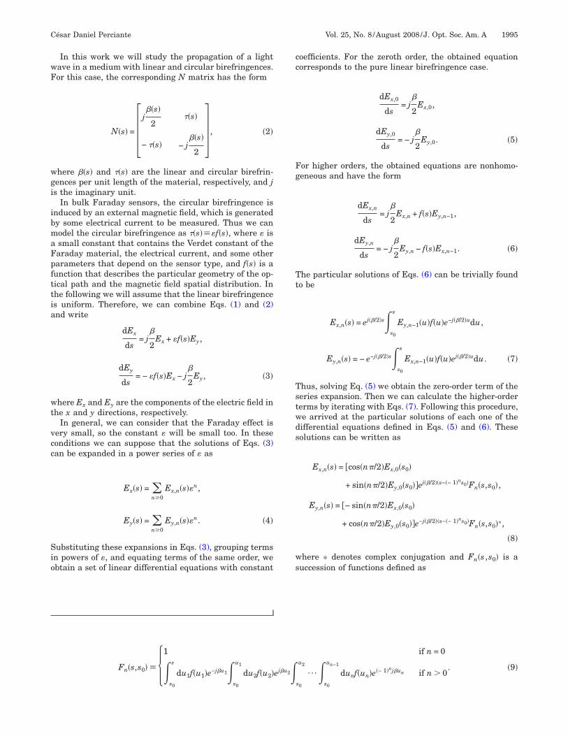
In this work we will study the propagation of a lightave in a medium with linear and circular birefringences.or this case, the corresponding N matrix has the form
N�s� = � j��s�
2��s�
− ��s� − j��s�
2� , �2�
here ��s� and ��s� are the linear and circular birefrin-ences per unit length of the material, respectively, and js the imaginary unit.
In bulk Faraday sensors, the circular birefringence isnduced by an external magnetic field, which is generatedy some electrical current to be measured. Thus we canodel the circular birefringence as ��s���f�s�, where � issmall constant that contains the Verdet constant of thearaday material, the electrical current, and some otherarameters that depend on the sensor type, and f�s� is aunction that describes the particular geometry of the op-ical path and the magnetic field spatial distribution. Inhe following we will assume that the linear birefringences uniform. Therefore, we can combine Eqs. (1) and (2)nd write
dEx
ds= j
�
2Ex + �f�s�Ey,
dEy
ds= − �f�s�Ex − j
�
2Ey, �3�
here Ex and Ey are the components of the electric field inhe x and y directions, respectively.
In general, we can consider that the Faraday effect isery small, so the constant � will be small too. In theseonditions we can suppose that the solutions of Eqs. (3)an be expanded in a power series of � as
Ex�s� = �n�0
Ex,n�s��n,
Ey�s� = �n�0
Ey,n�s��n. �4�
ubstituting these expansions in Eqs. (3), grouping termsn powers of �, and equating terms of the same order, webtain a set of linear differential equations with constant
s0 s0
oefficients. For the zeroth order, the obtained equationorresponds to the pure linear birefringence case.
dEx,0
ds= j
�
2Ex,0,
dEy,0
ds= − j
�
2Ey,0. �5�
or higher orders, the obtained equations are nonhomo-eneous and have the form
dEx,n
ds= j
�
2Ex,n + f�s�Ey,n−1,
dEy,n
ds= − j
�
2Ey,n − f�s�Ex,n−1. �6�
he particular solutions of Eqs. (6) can be trivially foundo be
Ex,n�s� = ej��/2�s�s0
s
Ey,n−1�u�f�u�e−j��/2�udu,
Ey,n�s� = − e−j��/2�s�s0
s
Ex,n−1�u�f�u�ej��/2�udu. �7�
hus, solving Eq. (5) we obtain the zero-order term of theeries expansion. Then we can calculate the higher-ordererms by iterating with Eqs. (7). Following this procedure,e arrived at the particular solutions of each one of theifferential equations defined in Eqs. (5) and (6). Theseolutions can be written as
Ex,n�s� = �cos�n�/2�Ex,0�s0�
+ sin�n�/2�Ey,0�s0�ej��/2��s−�− 1�ns0�Fn�s,s0�,
Ey,n�s� = �− sin�n�/2�Ex,0�s0�
+ cos�n�/2�Ey,0�s0�e−j��/2��s−�− 1�ns0�Fn�s,s0�*,
�8�
here * denotes complex conjugation and Fn�s ,s0� is auccession of functions defined as
Fn�s,s0� � 1 if n = 0
�s
du1f�u1�e−j�u1�u1
du2f�u2�ej�u2�u2
¯�un−1
dunf�un�e�− 1�nj�un if n � 0. �9�
s0 s0

F
S
wts
teT
w
Tswfg
3CEsrtso
ethtcdscol
cb
w
wcoh
gssmcmasr
wtpa
pcEp
ttato
wp
Fpa
1996 J. Opt. Soc. Am. A/Vol. 25, No. 8 /August 2008 César Daniel Perciante
irst, let us note that for n�0,
dFn�s,s0�
ds= f�s�e−j�sFn−1�s,s0�*. �10�
ubstituting Eq. (8) into Eq. (4), we obtain
Ex�s� = �n�0
��cos�n�/2�Ex,0�s0�
+ sin�n�/2�Ey,0�s0�ej��/2��s−�− 1�ns0�Fn�s,s0���n,
Ey�s� = �n�0
��− sin�n�/2�Ex,0�s0�
+ cos�n�/2�Ey,0�s0�e−j��/2��s−�− 1�ns0�Fn�s,s0�*��n,
�11�
hich verifies the first-order differential equation (3) andhe initial conditions at s=s0. Then, it is the generalolution of the problem.
Now we can write Eqs. (11) in matrix notation to obtainhe Jones M matrix that corresponds to the system thatxtends from point s0 to s1 and is described by Eqs. (3).his matrix is
M�s1,s0� = A�s1,s0� B�s1,s0�
− B�s1,s0�* A�s1,s0�*� , �12�
ith
A�s1,s0� = ej��/2��s1−s0� �m�0
�− 1�mF2m�s1,s0��2m� ,
B�s1,s0� = ej��/2��s+s0� �m�0
�− 1�mF2m+1�s1,s0��2m+1� .
�13�
herefore, we have arrived at an exact expression that de-cribes the change of the polarization state of a planeave that propagates in a material medium with nonuni-
orm circular birefringence and uniform linear birefrin-ence.
. APPLICATION TO A SIMPLE FARADAYURRENT SENSORquation (1) has been generally used in the literature totudy the effects of linear birefringence in Faraday cur-ent sensors. As far as we know, it is always applied withhe assumption that both � and � are uniform (i.e., con-tant along the optical path). In these cases, the first-rder differential equation is trivially solved.
Intrinsic sensors have an optical fiber as the sensing el-ment. In general, the fiber is arranged as a coil aroundhe current conductor [2–7], but other fiber architecturesave been studied [8]. In these cases, the distance be-ween the optical path and the current conductor can beonsidered constant, so that the circular birefringence in-uced by the Faraday effect is also constant. The mainource of linear birefringence is due to internal stressaused by fiber bending. As this depends on the curvaturef the fiber and the radius of the coil is constant, theinear birefringence may be assumed constant, too.
Thus, solving the differential equation (1) with theseonditions leads to the well-known relationship [2]etween the input and the output polarization states.
MC = AC BC
− BC AC*� , �14�
ith
AC = cos��/2� + j sin��/2�cos���,
BC = sin��/2�sin���, �15�
here ��L, ��L, �2= � /2�2+2, tan����2 /, * is theomplex conjugation operator, and L is the length of theptical path. The C subscripts are used to denote theypothesis that � and � are constants.Extrinsic sensors are systems that use bulk crystals or
lasses as sensing elements [9–12]. In these cases, theituation is different. The optical path is composed of auccession of straight lines inside a bulk material. As theagnetic field is not constant along the optical path, the
ircular birefringence � is not constant either and theodel given in Eqs. (14) and (15) is strictly not correct. Asconsequence, the use of these equations for the mea-
urement of the current in extrinsic Faraday sensors willesult in unwanted measurement errors.
In order to simplify the following study, we will workith the simplest extrinsic Faraday current sensor archi-
ecture, which is shown in Fig. 1. It is composed of an in-ut polarizer, a bulk Faraday material, and an outputnalyzer.Even when this is not the most usual architecture ap-
lied in real sensors, it is enough to do a quantitativeomparison between the approximated model given byqs. (14) and (15) and the exact solution presented in therevious section.In this case, the light passes just once through the sys-
em and the output light intensity contains the informa-ion of the electric current that induces the magnetic fieldlong the optical path. The Jones M matrix that relateshe input state of polarization with the output one will bef the form
M = PoutFPin, �16�
here Pin and Pout are the matrices that correspond to theolarizer and analyzer, respectively, and F is the matrix
ig. 1. Simple current sensor architecture composed of an inputolarizer, a bulk Faraday material as the sensing element, andn output analyzer.

tl
atogWeirtE
its
cr
g
wcc
cE
tbmcvm
d�
saa
A
To
ss
pc
4AIbFd
César Daniel Perciante Vol. 25, No. 8 /August 2008 /J. Opt. Soc. Am. A 1997
hat describes the change of the polarization state of theight that propagates inside the Faraday material.
In many works presented in the literature (e.g., see [2]nd references therein) the matrix F is considered to behe one defined in Eq. (14). Even when this model is validnly for constant linear and circular birefringences, it isenerally accepted for the study of bulk Faraday sensors.hat several authors do (see, for example, [13] and refer-
nces therein) is to calculate the total rotation angle asf there is no linear birefringence present and the totaletardance as if there is no circular birefringence. Thenhey substitute the results into the coefficients ofqs. (15).Clearly, this is not equivalent to solving the correspond-
ng differential equation, but of course it can be arguedhat this procedure is simple and a good approximation inome cases.
For correctly studying the mixed effects of linear andircular birefringences in a bulk Faraday sensor, theesults of the previous section must be used.
In the case of the system of Fig. 1, the circular birefrin-ence can be simply expressed as
��s� = � I�0Vd
4�� 1
d2 + s2 , �17�
here �0 is the magnetic permeability of vacuum, I is theurrent through the conductor, and V is the Verdet
onstant of the Faraday material. wmtw
w
Opo
t
If d�s for all s along the optical path (i.e., d�L), the soordinate could be neglected in the denominator ofq. (17) and ��I�0V /4�d along the optical path.As in general, the Faraday effect is very small. In prac-
ical cases, the sensing element (e.g., bulk crystal) muste installed near the current conductor in order to maxi-ize the measured signal and to minimize the magnetic
ross talk. Thus, the former hypothesis �d�L� is notalid, and the spatial dependence of the magnetic fieldust be considered.Therefore, for this case we can define the function f as a
imensionless function given by f�s��d2 / �d2+s2� and�I�0V /4�d.For the system of Fig. 1, we will assume that L=d, so
0=−d and s1=d. This would be the case of the sensingrm of a square-shaped bulk current sensor. Thus, evalu-ting Eqs. (13) we obtain
A = ej�d �n�0
�− 1�nF2n�d��2n� ,
B = �n�0
�− 1�nF2n+1�d��2n+1, �18�
ith
Fn�d� � 1 if n = 0
�−d
d du1e−j�u1
d2 + u12 �
−d
u1 du2ej�u2
d2 + u22 �
−d
u2
¯�−d
un−1 dune�− 1�nj�un
d2 + un2
if n � 0. �19�
nd the Jones M matrix is
M = A B
− B A*� . �20�
he conjugation of B is omitted because, by the symmetryf the problem, B is a real number.
We have obtained the exact Jones M matrix that corre-ponds to the sensing head of a very simple currentensor.
As each term of matrix (20) is a series expansion, inractice, only low-order terms of these series will beonsidered.
. COMPARISON BETWEENPPROXIMATIONS
n this section we present a quantitative comparisonetween the Jones M matrices that model the simplearaday sensor of Fig. 1 obtained by the two methodsescribed before. On the one hand, we have the Jones M
atrix MC of Eq. (14), while on the other, we have theruncated version of the exact matrix of Eq. (20), whiche will denote
MT � AT BT
− BT AT*� , �21�
ith
AT = ej�d �n=0
1
�− 1�nF2n�d��2n� = ej�d�1 − �2F2�d��,
BT = �n=0
1
�− 1�nF2n+1�d��2n+1 = �F1�d� − �3F3�d�. �22�
bserve that we considered only the two first terms of theower series expansion that correspond to each coefficientf M (i.e., A and B).
As seen before, the value of the constant � depends onhe sensor type, the optical characteristics of the Faraday

mwnV(c
rtv�
f
fda
flb
ceg
trc
1998 J. Opt. Soc. Am. A/Vol. 25, No. 8 /August 2008 César Daniel Perciante
aterial, and the applied electrical current. Even for aide range of currents (e.g., 0 to 5 kA or more), the mag-itude of � will be small. For example, let us assume aerdet constant V=134 rad/T m [terbium gallium garnet
TGG) at a wavelength �=633 nm] and d=0.2 m. In thisase, for a current I=5 kA, �=I�0V /4�d=0.34 rad/m.
For this particular case, we calculated the relative er-ors of the coefficients that compose the Jones matrix ofhe system for a current range I=0 A to 5 kA and severalalues of linear birefringence per unit length between=0 rad/m and �=0.1 rad/m.The relative errors are calculated as
AC =�AC − A�
�A�� 100, BC =
�BC − B�
�B�� 100 �23�
or the constant � and � case, and
Fig. 2. Relative errors of A (a) and B (b) as a functio
C CAT =�AT − A�
�A�� 100, BT =
�BT − B�
�B�� 100 �24�
or the truncated series expansion case. In both cases �U�enotes the magnitude of the complex number U and And B are calculated by numerical integration of Eq. (1).In Fig. 2 we graph the relative errors of AC and BC as
unctions of the applied current for several values of theinear birefringence �. In Fig. 3 we show the same graphsut for AT and BT coefficients.First, as expected, from the numerical comparison we
an observe that for very small linear birefringence andlectrical current (which induces a small circular birefrin-ence), both approximate models are equivalent.
As both models are approximations of the exact solu-ion, it was also expected that for every value of linear bi-efringence, the relative errors increase when the electri-al current is increased. In the first case, this happens
e applied electric current and the linear birefringence.
n of th
bsfnt
tigwaB
idae
5It
pruf
cwml
srrjoimmsis
César Daniel Perciante Vol. 25, No. 8 /August 2008 /J. Opt. Soc. Am. A 1999
ecause, as the current increases, the hypothesis of con-tant circular birefringence is less valid. In the other case,or the truncated series model, this happens because theeglected high-order terms become relevant compared tohe ones considered in Eqs. (22).
However, if we observe the absolute values of the rela-ive errors, we can see that the truncated series solutions much better. For the studied ranges of linear birefrin-ence and currents on the described particular sensor,hile the relative errors of AC and BC are less than 1.25%nd 15�10−2%, respectively, the relative errors of AT andT are less than 3.5�10−4% and 13�10−3%, respectively.Therefore, using the truncated series model of Eqs. (22)
nstead of the usually accepted approximation, we canesign Faraday current sensors that could achieveccuracies of the order of 0.01% or less for a wide range oflectrical currents.
. CONCLUSIONSn this work we found the exact solution for the differen-ial equation that describes the evolution of the state of
T T
olarization of a light wave propagating through a mate-ial medium with uniform linear birefringence and a non-niform external magnetic field, which induces a nonuni-orm circular birefringence due to the Faraday effect.
We applied the results to a simple architecture Faradayurrent sensor and compared the relative errors achievedith the new solution and with the usually acceptedodel, which is based on the assumption that both the
inear and circular birefringences are constants.Applying the obtained theoretical results to a very
imple current sensor architecture, we found that theelative errors of a Faraday current sensor could beeduced approximately 1 order of magnitude. As we usedust some low-order terms of the power series expansionf the coefficients of the Jones M matrix, the increasen accuracy is achieved with a simple low-order polyno-
ial model. In practice, this is very simple to imple-ent in almost any type of digital system. Therefore, a
imple change in the signal processing algorithms couldmprove the accuracy of existing bulk Faraday currentensors.
Fig. 3. Relative errors of A (a) and B (b) as a function of the applied electric current and the linear birefringence.

R
1
1
1
1
2000 J. Opt. Soc. Am. A/Vol. 25, No. 8 /August 2008 César Daniel Perciante
EFERENCES1. R. C. Jones, “A new calculus for the treatment of optical
systems. VII. Properties of the N-matrices,” J. Opt. Soc.Am. 38, 671–685 (1948).
2. Y. N. Ning, Z. P. Wang, A. W. Palmer, K. T. V. Grattan, andD. A. Jackson, “Recent progress in optical current sensingtechniques,” Rev. Sci. Instrum. 66, 3097–3111 (1995).
3. J. Rogers, J. Xu, and J. Yao, “Vibration immunity foroptical-fiber current measurement,” J. Lightwave Technol.13, 1371–1377 (1995).
4. P. Menke and T. Bosselmann, “Temperature compensationin magnetooptic AC current sensors using an intelligentAC–DC signal evaluation,” J. Lightwave Technol. 13,1362–1370 (1995).
5. A. H. Rose, S. M. Etzel, and K. B. Rochford, “Optical fibercurrent sensors in high electric field environments,” J.Lightwave Technol. 17, 1042–1048 (1999).
6. X. Fang, A. Wang, R. G. May, and R. O. Claus, “Areciprocal-compensated fiber-optic electric current sensor,”J. Lightwave Technol. 12, 1882–1890 (1994).
7. H. Lin, W.-W. Lin, M.-H. Chen, and S.-C. Huang, “Vibrationinsensitive optical fiber current sensor with a modified
reciprocal reflection interferometer,” Opt. Eng.(Bellingham) 38, 1722–1729 (1999).
8. F. Maystre and A. Bertholds, “Magneto-optic current sensorusing a helical-fiber Fabry–Perot resonator,” Opt. Lett. 14,587–589 (1989).
9. C. Li, X. Cui, and T. Yoshino, “Optical electric-power sensorby use of one bismuth germanate crystal,” J. LightwaveTechnol. 21, 1328–1333 (2003).
0. X. Ma and C. Luo, “A method to eliminate birefringence of amagneto-optic AC current transducer with glass ringsensor head,” IEEE Trans. Power Deliv. 13, 1015–1019(1998).
1. K. Kyuma, S. Tai, M. Nunoshita, N. Mikami, and Y. Ida,“Fiber-optic current and voltage sensors using aBi12GeO20 single crystal,” J. Lightwave Technol. LT-1,93–97 (1983).
2. E. A. Ulmer, Jr., “A high-accuracy optical currenttransducer for electric power systems,” IEEE Trans. PowerDeliv. 5, 892–898 (1990).
3. Z. P. Wang, Q. B. Li, Y. Qi, Z. J. Huang, and J. H. Shi,“Effect of dispersion of linear birefringence upon thesensitivity of an optical current sensor,” Opt. LaserTechnol. 36, 587–590 (2004).