Embed Size (px)
Citation preview

© 2013 Agilent Technologies
EW Testing: Capture, Measurement, and Emulation
Presented by: Walt Schulte, Agilent Technologies

© 2013 Agilent Technologies 2
© 2013 Agilent Technologies
Problem
• Jamming is a response to an identified radar signal
• Jamming techniques take time to work
• You must therefore capture and analyze an entire jamming event

© 2013 Agilent Technologies
Measurement Challenges: Dynamic PRI
1. 2.
• Signal Source: PRI increasing from 50 us to 100 us in 100 pulses
• Signal Analyzer: RBW < .3 x min PRF
Single sweep, delta marker:
PRF = 12.750 kHz Single sweep, delta marker:
PRF = 17 kHz

© 2013 Agilent Technologies 4
© 2013 Agilent Technologies
Measurement Challenges: Dynamic PRI
• Limited analysis time
• Scalar only: no doppler/phase
• Painful automation

© 2013 Agilent Technologies 5
© 2013 Agilent Technologies
Measurement Challenges: Dynamic Doppler
• Sweep times too slow relative to rate of doppler change
• Display shows a swept spectrum over entire sweep time
© 2013 Agilent Technologies
• Capture the Event
• Measure the Event
Solution
PXA
89600
VSA
© 2013 Agilent Technologies 7
© 2013 Agilent Technologies
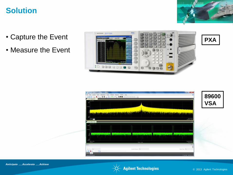
Solution: Test Setup
DUT
(Jammer)
Agilent X-Series
Analyzer
LAN
Computer
w/Agilent 89600
VSA
• Digitize
• Record
• Analyze
Caution: Max. input
power +30 dBm (1 Watt)

© 2013 Agilent Technologies 8
© 2013 Agilent Technologies
Alternative Setup
DUT
(Jammer)
Agilent X-Series
Analyzer running
VSA internally
• Digitize
• Record
•Analyze
Caution: Max. input
power +30 dBm (1 Watt)

© 2013 Agilent Technologies 9
© 2013 Agilent Technologies
Agenda
Transmitter Test
• Capture
• Measurement
Receiver Test
• Emulation

© 2013 Agilent Technologies 10
© 2013 Agilent Technologies
Capture: Span/Record Length
1
10
100
1000
1 10 100 1000
Cap
ture
Len
gth
(sec)
Measurement Span (MHz)
PXA Capture Length vs. Span
Spanxfs 28.1

© 2013 Agilent Technologies 11
© 2013 Agilent Technologies
Capture: Span
rtBW /35.
devchirpBW -or-
1.
2. xBWfs 5
3. 28.1/sfspan
.35/30ns ~ 12 MHz
5 x 12 MHz = 60 MHz
60 MHz/1.28 = 46 MHz
46 MHz ~ 50 MHz
© 2013 Agilent Technologies
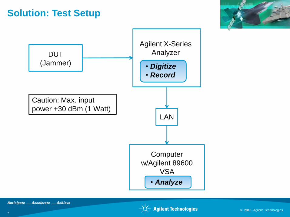
• Multiple options available
• Most flexible is “IF Mag”
• Use negative trigger delay
Capture: Triggering on the First Pulse
89600 VSA

© 2013 Agilent Technologies 13
© 2013 Agilent Technologies
Capture: Recording the Signal

© 2013 Agilent Technologies 14
© 2013 Agilent Technologies
Capture: Recording Length

© 2013 Agilent Technologies 15
© 2013 Agilent Technologies
Capture: Recording the Signal
Record
89600 VSA

© 2013 Agilent Technologies 16
© 2013 Agilent Technologies
Agenda
Transmitter Test
• Capture
• Measurement
Receiver Test
• Emulation

© 2013 Agilent Technologies 17
© 2013 Agilent Technologies
Measurement: J/S, PRI
© 2013 Agilent Technologies 18
© 2013 Agilent Technologies
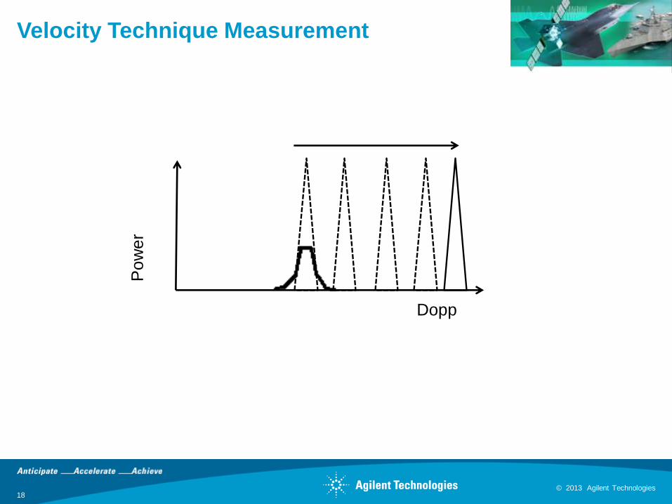
Velocity Technique Measurement
Po
we
r
Dopp

© 2013 Agilent Technologies 19
© 2013 Agilent Technologies
Measurement: Frequency Resolution

© 2013 Agilent Technologies
Signal Processing So Far…
• Gated FFT
• Sample period of
15.625 ns
• Correspondingly, a 64
MSa/s sample rate
• We get much better
frequency resolution
through zero padding
5 us gate time. N = 5 us / 15.625 ns/Sa ~ 300 samples
300 samples padded out to 406,601 FFT points

© 2013 Agilent Technologies 21
© 2013 Agilent Technologies
Frequency Resolution
N
ff s 64 MHz / 409,601 ~ 150 Hz

© 2013 Agilent Technologies 22
© 2013 Agilent Technologies
Measurement: Gated Spectrum
GHzft cN 10,1
kHzft cN 822.4,
© 2013 Agilent Technologies 23
© 2013 Agilent Technologies
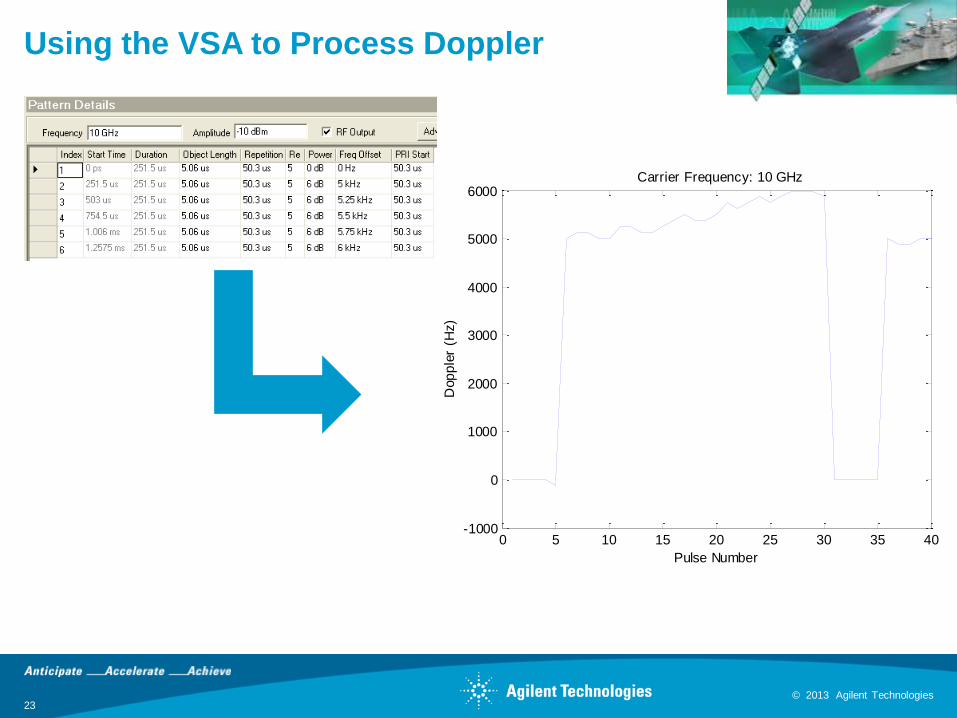
Using the VSA to Process Doppler
0 5 10 15 20 25 30 35 40-1000
0
1000
2000
3000
4000
5000
6000
Dop
ple
r (H
z)
Pulse Number
Carrier Frequency: 10 GHz

© 2013 Agilent Technologies 24
© 2013 Agilent Technologies
More Helpful Measurements: OBW
5 us PW, gated FFT of 900 MHz chirp
© 2013 Agilent Technologies 25
© 2013 Agilent Technologies
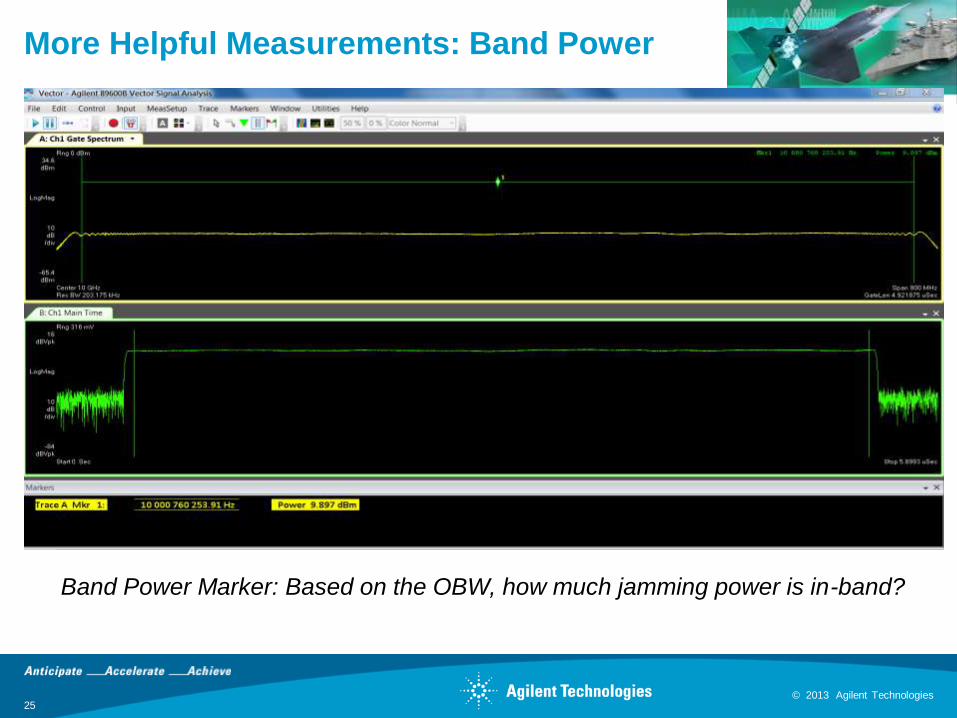
More Helpful Measurements: Band Power
Band Power Marker: Based on the OBW, how much jamming power is in-band?

© 2013 Agilent Technologies 26
© 2013 Agilent Technologies
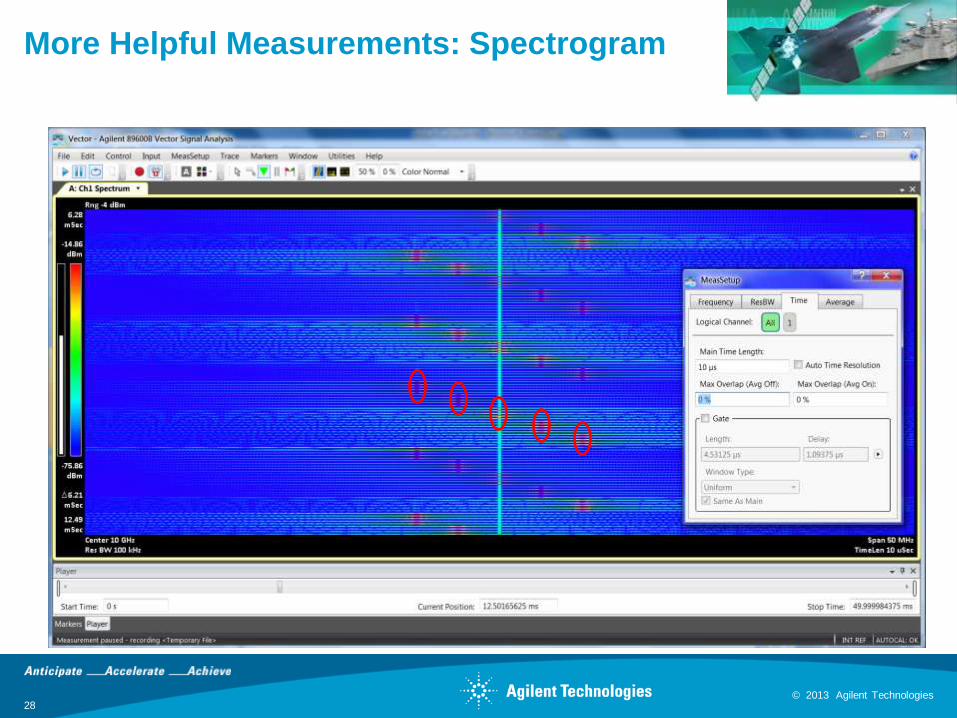
More Helpful Measurements: Spectrogram

© 2013 Agilent Technologies 27
© 2013 Agilent Technologies
More Helpful Measurements: Spectrogram
© 2013 Agilent Technologies 28
© 2013 Agilent Technologies
More Helpful Measurements: Spectrogram

© 2013 Agilent Technologies 29
© 2013 Agilent Technologies
Deep-Memory Record / Playback
Record and Playback 100% of Long Duration RF Signals (No Gaps)
minutes days hours
+ High Fidelity Signal
Acquisition and Generation
Continuous Capture and Playback
Modern Equipment
S i g n a l R e c o r d e r s E x t e n d T i m e

© 2013 Agilent Technologies
Turning Data into Information
30
Record 100% of Signal Content (minutes, hours, days)
Identify Signals of Potential Interest
Replay “Interesting”
Portions
Analyze/ Demod
RF Environment
Take Appropriate Action
Raw Data
Info
“Stare” at spectrum for extended periods of time
Operate on very large data sets
Recreate with high signal fidelity
Leverage investment in existing signal analysis tools using open-format data files
X-Series + IQC
89601B
CPG + VSG
Spectro-X

© 2013 Agilent Technologies 31
© 2013 Agilent Technologies
Agenda
Transmitter Test
• Capture
• Measurement
Receiver Test
• Emulation
© 2013 Agilent Technologies
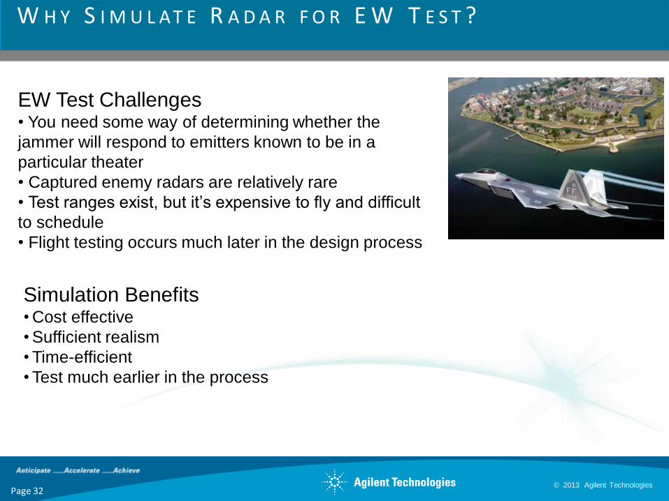
W H Y S I M U L AT E R A D A R F O R E W T E S T ?
EW Test Challenges • You need some way of determining whether the
jammer will respond to emitters known to be in a
particular theater
• Captured enemy radars are relatively rare
• Test ranges exist, but it’s expensive to fly and difficult
to schedule
• Flight testing occurs much later in the design process
Page 32
Simulation Benefits • Cost effective
• Sufficient realism
• Time-efficient
• Test much earlier in the process

© 2013 Agilent Technologies
What Radar Parameters Should Be
Simulated?
• Antenna Properties
• Pulse Parameters
• Pulse Repetition Interval
• Power Levels

© 2013 Agilent Technologies
•Bore-Sight – Maximum gain of the
antennas main lobe or beam pointing at the
target.
•Bearing Angle - The bearing angle of the
target can be determined by moving the
antenna beam to the maximum return.
•Beam width – ½ Power points in the main
lobe measured in angular width AZ/EL
degrees.
•Side Lobe Level - the level of energy on
the side lobes relative to the main lobe or
beam
•Back Lobe – the energy emitting in the
opposite direction of the main beam.
A N T E N N A P AT T E R N P R O P E R T I E S A N D D E F I N I T I O N S
Page 34

© 2013 Agilent Technologies
E X A M P L E 1 – C I R C U L A R A N T E N N A S C A N
(Elevation)
Degrees
Reciever
Vertical
Location
Receiver
Horizontal Location
(Azimuth) - Degrees
Circular ScanY
°
0°
+90°
+180°
+270°
Scan Rate RPM
X°
Page 35

© 2013 Agilent Technologies
E X A M P L E 2 – C O N I C A L A N T E N N A S C A N Feed horn nutating in a small circular orbit
Page 36

© 2013 Agilent Technologies
E X A M P L E 3 – B I D I R E C T I O N A L R A S T E R A N T E N N A S C A N
Page 37

© 2013 Agilent Technologies
Amplitude seen by the jammer due to scan
38
N7620B Signal Studio for pulse building

© 2013 Agilent Technologies
Pulse Repetition Interval
Choice of PRI • Crucial for range or doppler
measurement
• Helps reduce
mainlobe/sidelobe clutter
• Helps eliminate ground moving
targets
• Reduces range/doppler
ambiguities, blind zones and
blind speeds
• Aids in power management
• Helps reduce POI
• Mode switching
EW systems use radar PRI for identification

© 2013 Agilent Technologies
PRI Switching
B A
C t
A B
rf
1
PW
Range
C
uR
© 2013 Agilent Technologies
Pulse Parameters
• Pulse width: affects average power for a given peak power, affects time-bandwidth product and range resolution
• Rise Time/Fall Time: affected by analog BW of the radar
• Modulation-on-pulse: chosen for range resolution desired
• Jitter: may be intentional to eliminate blind speeds or clutter, may be due to thermal fluctuations or system impairments from power supplies

© 2013 Agilent Technologies
Scenario Name
Source Parameters
Pulse Envelope properties – tr, tf, PW
Pulse Width Patterns
PRI Patterns
Modulation on Pulse Properties – Chirp, Barker, FSK, etc
Antenna Scanning Type
Antenna Radiation Type
Antenna Beam Width – AZ, El
Antenna Null Depth
Receiver Location
S C E N A R I O D ATA B A S E – I M P O R T I N G & E X P O R T I N G
Page 42
Intelligence
Database Spreadsheet Simulation at RF (emulation)

© 2013 Agilent Technologies
Agilent N7620B Signal Studio
For Pulse Building Software
43
I Q
Features
• flexible GUI
• Complex pulse/PRI patterns/antenna scans
• wideband modulation on pulse
• corrected test signals
• .csv importing
• COM API

© 2013 Agilent Technologies 44
© 2013 Agilent Technologies
Summary
Transmitter Test
• Capture
• Measurement
Receiver Test
• Emulation
© 2013 Agilent Technologies 45
© 2013 Agilent Technologies
Summary
• More information can be found on our website:
www.agilent.com/find/pxa PXA Signal Analyzer
www.agilent.com/find/psg PSG Signal Generator
www.agilent.com/find/vsa 89600 VSA Software
www.agilent.com/find/n7620b Signal Studio for Pulse Building
www.agilent.com/find/n6171b MATLAB
www.agilent.com/find/xcom X-com systems
• The application note entitled “Making Wideband Measurements” (5990-
9108EN) is found here:
http://cp.literature.agilent.com/litweb/pdf/5990-9108EN.pdf
• VSA trial licenses available!
http://www.home.agilent.com/agilent/download.jspx?cc=US&lc=eng&nid=-
33713.958604&pageMode=DL