Embed Size (px)
Citation preview
1
EW00E.00TS-4
Printed May 10, 2021
TSUBAKI Worm Gear Reducer
EW/EWJ/EWM/EWJM series SW/SWJ/SWM/SWJM series
Instruction Manual
TSUBAKIMOTO CHAIN CO.
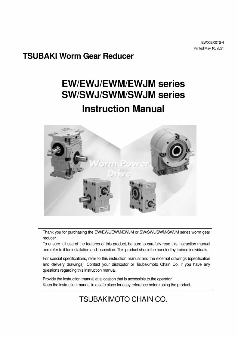
Thank you for purchasing the EW/EWJ/EWM/EWJM or SW/SWJ/SWM/SWJM series worm gear
reducer.
To ensure full use of the features of this product, be sure to carefully read this instruction manual
and refer to it for installation and inspection. This product should be handled by trained individuals.
For special specifications, refer to this instruction manual and the external drawings (specification
and delivery drawings). Contact your distributor or Tsubakimoto Chain Co. if you have any
questions regarding this instruction manual.
Provide the instruction manual at a location that is accessible to the operator.
Keep the instruction manual in a safe place for easy reference before using the product.
2
Contents Safety Precautions ··························································································· 3
1.After Purchase ······························································································ 5
1-1.Checking the contents ············································································· 5
1-2.Information to provide when contacting customer service ······························· 5
1-3.Model number designation ······································································· 5
2.Transport ····································································································· 11
3.Installation ···································································································· 11
3-1.Solid output shaft type ············································································· 11
3-2.Hollow output shaft type ··········································································· 13
4.Connection ··································································································· 15
4-1.Verifying the direction of rotation ································································ 15
4-2.Connection ···························································································· 15
5.Lubrication ··································································································· 17
5-1.Recommended lubrication oil ···································································· 17
5-2.Approximate oil volume ··········································································· 17
5-3.Replacing the lubrication oil ······································································ 17
5-4.Supplying grease (Semi-standard package) ················································ 18
6.Operation ····································································································· 19
6-1.Double checking before operation ······························································ 19
6-2.Trial run ································································································ 19
6-3.Load ···································································································· 19
6-4.Verification after operation starts ································································ 19
7.Maintenance ································································································· 20
7-1.Maintenance precautions ········································································· 20
7-2.Daily inspection ······················································································ 20
7-3.Inspection and replacement of the oil seal ··················································· 20
8.Handling the standard motor and brake specifications ··········································· 21
8-1.Standard motor specifications ········································································ 21
8-2.Specifications and construction of SLB brake (for 0.1 to 2.2 kW motor with brake)
and gap adjustment ····················································································· 33
8-3.Specifications and construction of VNB brake (for 3.7 to 5.5 kW motor with brake)
and gap adjustment ····················································································· 35
9.Handling a Semi-standard Package ·································································· 36
9-1.Handling POWER-LOCK specifications ······················································ 36
9-2.Handling the taper bush specifications ························································ 38
10.Disassembly and Assembly ··········································································· 39
11.Troubleshooting ··························································································· 40
12.Internal Construction and Parts List ································································· 40
12-1.Internal construction ·············································································· 40
12-2.Parts list ······························································································ 45
13.Storage ······································································································ 47
14.Others ······································································································· 48
15.Warranty ···································································································· 48
16.CE Certified Motor ························································································ 49
17.UL Listed Motor ··························································································· 50
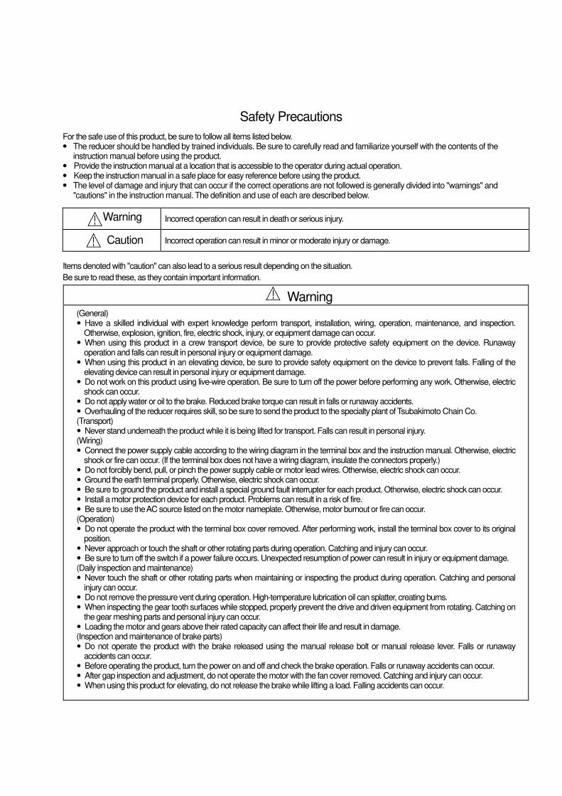
Safety Precautions
For the safe use of this product, be sure to follow all items listed below. � The reducer should be handled by trained individuals. Be sure to carefully read and familiarize yourself with the contents of the
instruction manual before using the product. � Provide the instruction manual at a location that is accessible to the operator during actual operation. � Keep the instruction manual in a safe place for easy reference before using the product. � The level of damage and injury that can occur if the correct operations are not followed is generally divided into "warnings" and
"cautions" in the instruction manual. The definition and use of each are described below.
Warning
Incorrect operation can result in death or serious injury.
Caution Incorrect operation can result in minor or moderate injury or damage.
Items denoted with "caution" can also lead to a serious result depending on the situation.
Be sure to read these, as they contain important information.
(General) � Have a skilled individual with expert knowledge perform transport, installation, wiring, operation, maintenance, and inspection.
Otherwise, explosion, ignition, fire, electric shock, injury, or equipment damage can occur. � When using this product in a crew transport device, be sure to provide protective safety equipment on the device. Runaway
operation and falls can result in personal injury or equipment damage. � When using this product in an elevating device, be sure to provide safety equipment on the device to prevent falls. Falling of the
elevating device can result in personal injury or equipment damage. � Do not work on this product using live-wire operation. Be sure to turn off the power before performing any work. Otherwise, electric
shock can occur. � Do not apply water or oil to the brake. Reduced brake torque can result in falls or runaway accidents. � Overhauling of the reducer requires skill, so be sure to send the product to the specialty plant of Tsubakimoto Chain Co. (Transport) � Never stand underneath the product while it is being lifted for transport. Falls can result in personal injury. (Wiring) � Connect the power supply cable according to the wiring diagram in the terminal box and the instruction manual. Otherwise, electric
shock or fire can occur. (If the terminal box does not have a wiring diagram, insulate the connectors properly.) � Do not forcibly bend, pull, or pinch the power supply cable or motor lead wires. Otherwise, electric shock can occur. � Ground the earth terminal properly. Otherwise, electric shock can occur. � Be sure to ground the product and install a special ground fault interrupter for each product. Otherwise, electric shock can occur. � Install a motor protection device for each product. Problems can result in a risk of fire. � Be sure to use the AC source listed on the motor nameplate. Otherwise, motor burnout or fire can occur. (Operation) � Do not operate the product with the terminal box cover removed. After performing work, install the terminal box cover to its original
position. � Never approach or touch the shaft or other rotating parts during operation. Catching and injury can occur. � Be sure to turn off the switch if a power failure occurs. Unexpected resumption of power can result in injury or equipment damage. (Daily inspection and maintenance) � Never touch the shaft or other rotating parts when maintaining or inspecting the product during operation. Catching and personal
injury can occur. � Do not remove the pressure vent during operation. High-temperature lubrication oil can splatter, creating burns. � When inspecting the gear tooth surfaces while stopped, properly prevent the drive and driven equipment from rotating. Catching on
the gear meshing parts and personal injury can occur. � Loading the motor and gears above their rated capacity can affect their life and result in damage. (Inspection and maintenance of brake parts) � Do not operate the product with the brake released using the manual release bolt or manual release lever. Falls or runaway
accidents can occur. � Before operating the product, turn the power on and off and check the brake operation. Falls or runaway accidents can occur. � After gap inspection and adjustment, do not operate the motor with the fan cover removed. Catching and injury can occur. � When using this product for elevating, do not release the brake while lifting a load. Falling accidents can occur.
Warning
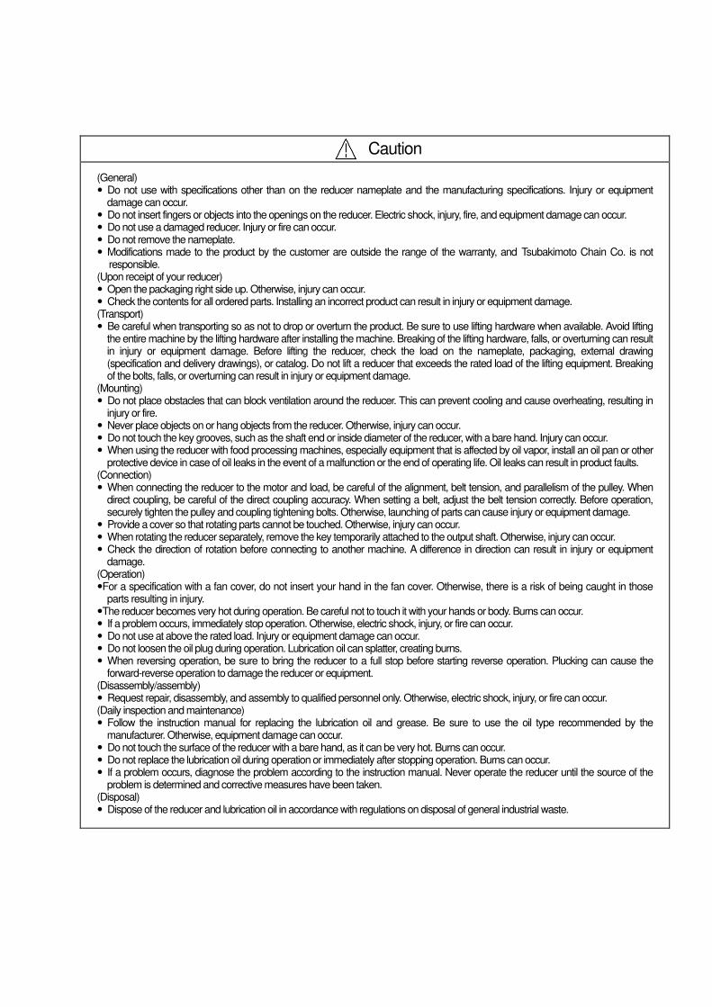
(General) � Do not use with specifications other than on the reducer nameplate and the manufacturing specifications. Injury or equipment
damage can occur. � Do not insert fingers or objects into the openings on the reducer. Electric shock, injury, fire, and equipment damage can occur. � Do not use a damaged reducer. Injury or fire can occur. � Do not remove the nameplate. � Modifications made to the product by the customer are outside the range of the warranty, and Tsubakimoto Chain Co. is not
responsible. (Upon receipt of your reducer) � Open the packaging right side up. Otherwise, injury can occur. � Check the contents for all ordered parts. Installing an incorrect product can result in injury or equipment damage. (Transport) � Be careful when transporting so as not to drop or overturn the product. Be sure to use lifting hardware when available. Avoid lifting
the entire machine by the lifting hardware after installing the machine. Breaking of the lifting hardware, falls, or overturning can result in injury or equipment damage. Before lifting the reducer, check the load on the nameplate, packaging, external drawing (specification and delivery drawings), or catalog. Do not lift a reducer that exceeds the rated load of the lifting equipment. Breaking of the bolts, falls, or overturning can result in injury or equipment damage.
(Mounting) � Do not place obstacles that can block ventilation around the reducer. This can prevent cooling and cause overheating, resulting in
injury or fire. � Never place objects on or hang objects from the reducer. Otherwise, injury can occur. � Do not touch the key grooves, such as the shaft end or inside diameter of the reducer, with a bare hand. Injury can occur. � When using the reducer with food processing machines, especially equipment that is affected by oil vapor, install an oil pan or other
protective device in case of oil leaks in the event of a malfunction or the end of operating life. Oil leaks can result in product faults. (Connection) � When connecting the reducer to the motor and load, be careful of the alignment, belt tension, and parallelism of the pulley. When
direct coupling, be careful of the direct coupling accuracy. When setting a belt, adjust the belt tension correctly. Before operation, securely tighten the pulley and coupling tightening bolts. Otherwise, launching of parts can cause injury or equipment damage.
� Provide a cover so that rotating parts cannot be touched. Otherwise, injury can occur. � When rotating the reducer separately, remove the key temporarily attached to the output shaft. Otherwise, injury can occur. � Check the direction of rotation before connecting to another machine. A difference in direction can result in injury or equipment
damage. (Operation) �For a specification with a fan cover, do not insert your hand in the fan cover. Otherwise, there is a risk of being caught in those
parts resulting in injury. �The reducer becomes very hot during operation. Be careful not to touch it with your hands or body. Burns can occur. � If a problem occurs, immediately stop operation. Otherwise, electric shock, injury, or fire can occur. � Do not use at above the rated load. Injury or equipment damage can occur. � Do not loosen the oil plug during operation. Lubrication oil can splatter, creating burns. � When reversing operation, be sure to bring the reducer to a full stop before starting reverse operation. Plucking can cause the
forward-reverse operation to damage the reducer or equipment. (Disassembly/assembly) � Request repair, disassembly, and assembly to qualified personnel only. Otherwise, electric shock, injury, or fire can occur. (Daily inspection and maintenance) � Follow the instruction manual for replacing the lubrication oil and grease. Be sure to use the oil type recommended by the
manufacturer. Otherwise, equipment damage can occur. � Do not touch the surface of the reducer with a bare hand, as it can be very hot. Burns can occur. � Do not replace the lubrication oil during operation or immediately after stopping operation. Burns can occur. � If a problem occurs, diagnose the problem according to the instruction manual. Never operate the reducer until the source of the
problem is determined and corrective measures have been taken. (Disposal) � Dispose of the reducer and lubrication oil in accordance with regulations on disposal of general industrial waste.
Caution
[ 1 ] After Purchase
1-1. Checking the contents
Check the following items upon receipt of your reducer.
Contact your distributor or Tsubakimoto Chain Co. if any defects are found.
Caution � Check the contents for all ordered parts. Installing an incorrect product can result in injury or equipment damage. � Open the packaging right side up. Otherwise, injury can occur.
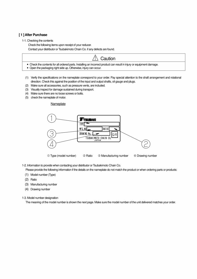
(1) Verify the specifications on the nameplate correspond to your order. Pay special attention to the shaft arrangement and rotational
direction. Check this against the position of the input and output shafts, oil gauge and plugs.
(2) Make sure all accessories, such as pressure vents, are included.
(3) Visually inspect for damage sustained during transport.
(4) Make sure there are no loose screws or bolts.
(5) check the nameplate of motor.
Nameplate
Type (model number) Ratio Manufacturing number Drawing number
1-2. Information to provide when contacting your distributor or Tsubakimoto Chain Co.
Please provide the following information if the details on the nameplate do not match the product or when ordering parts or products:
(1) Model number (Type)
(2) Ratio
(3) Manufacturing number
(4) Drawing number
1-3. Model number designation
The meaning of the model number is shown the next page. Make sure the model number of the unit delivered matches your order.
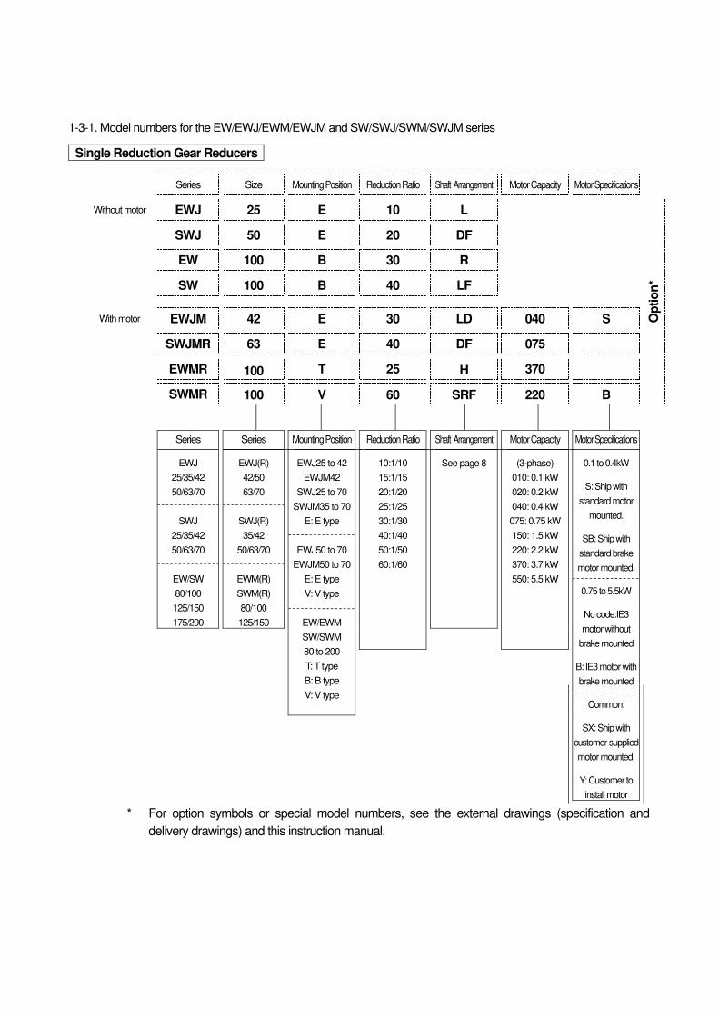
1-3-1. Model numbers for the EW/EWJ/EWM/EWJM and SW/SWJ/SWM/SWJM series
Single Reduction Gear Reducers
* For option symbols or special model numbers, see the external drawings (specification and
delivery drawings) and this instruction manual.
Series Size Mounting Position Reduction Ratio Shaft Arrangement Motor Capacity Motor Specifications
Without motor EWJ 25 E 10 L
Op
tio
n*
SWJ 50 E 20 DF
EW 100 B 30 R
SW 100 B 40 LF
With motor EWJM 42 E 30 LD 040 S
SWJMR 63 E 40 DF 075
EWMR 100 T 25 H 370
SWMR 100 V 60 SRF 220 B
Series
EWJ
25/35/42
50/63/70
SWJ
25/35/42
50/63/70
EW/SW
80/100
125/150
175/200
Series
EWJ(R)
42/50
63/70
SWJ(R)
35/42
50/63/70
EWM(R)
SWM(R)
80/100
125/150
Mounting Position
EWJ25 to 42
EWJM42
SWJ25 to 70
SWJM35 to 70
E: E type
EWJ50 to 70
EWJM50 to 70
E: E type
V: V type
EW/EWM
SW/SWM
80 to 200
T: T type
B: B type
V: V type
Reduction Ratio
10:1/10
15:1/15
20:1/20
25:1/25
30:1/30
40:1/40
50:1/50
60:1/60
Shaft Arrangement
See page 8
Motor Capacity
(3-phase)
010: 0.1 kW
020: 0.2 kW
040: 0.4 kW
075: 0.75 kW
150: 1.5 kW
220: 2.2 kW
370: 3.7 kW
550: 5.5 kW
Motor Specifications
0.1 to 0.4kW
S: Ship with
standard motor
mounted.
SB: Ship with
standard brake
motor mounted.
0.75 to 5.5kW
No code:IE3
motor without
brake mounted
B: IE3 motor with
brake mounted
Common:
SX: Ship with
customer-supplied
motor mounted.
Y: Customer to
install motor
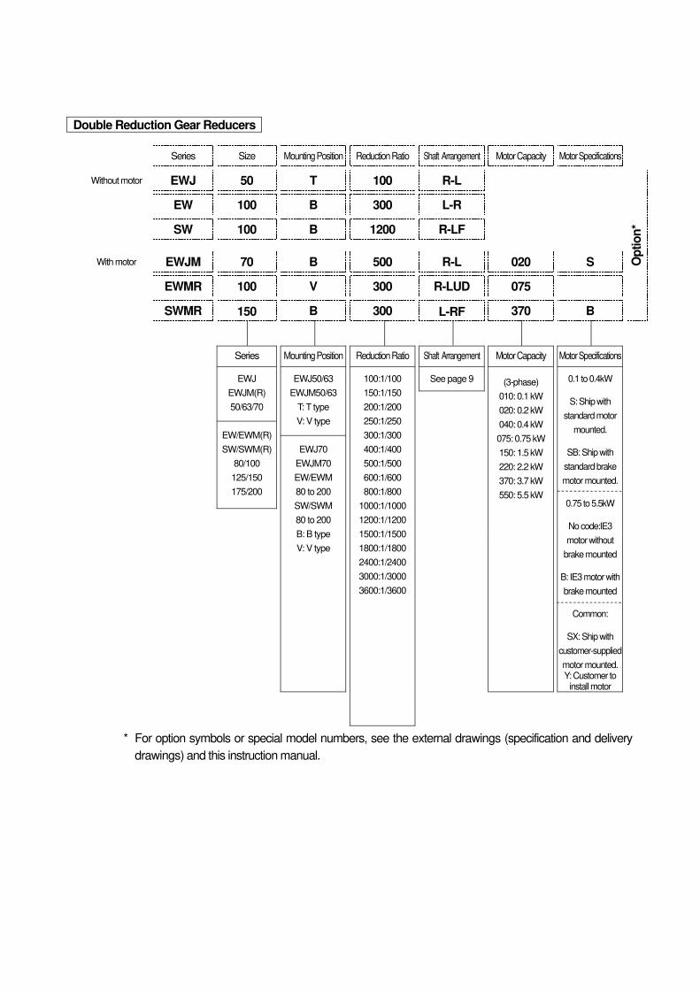
Double Reduction Gear Reducers
* For option symbols or special model numbers, see the external drawings (specification and delivery
drawings) and this instruction manual.
Series Size Mounting Position Reduction Ratio Shaft Arrangement Motor Capacity Motor Specifications
Without motor EWJ 50 T 100 R-L
Op
tio
n*
EW 100 B 300 L-R
SW 100 B 1200 R-LF
With motor EWJM 70 B 500 R-L 020 S
EWMR 100 V 300 R-LUD 075
SWMR 150 B 300 L-RF 370 B
Series
EWJ
EWJM(R)
50/63/70
EW/EWM(R)
SW/SWM(R)
80/100
125/150
175/200
Mounting Position
EWJ50/63
EWJM50/63
T: T type
V: V type
EWJ70
EWJM70
EW/EWM
80 to 200
SW/SWM
80 to 200
B: B type
V: V type
Reduction Ratio
100:1/100
150:1/150
200:1/200
250:1/250
300:1/300
400:1/400
500:1/500
600:1/600
800:1/800
1000:1/1000
1200:1/1200
1500:1/1500
1800:1/1800
2400:1/2400
3000:1/3000
3600:1/3600
Shaft Arrangement
See page 9
Motor Capacity
(3-phase)
010: 0.1 kW
020: 0.2 kW
040: 0.4 kW
075: 0.75 kW
150: 1.5 kW
220: 2.2 kW
370: 3.7 kW
550: 5.5 kW
Motor Specifications
0.1 to 0.4kW
S: Ship with
standard motor
mounted.
SB: Ship with
standard brake
motor mounted.
0.75 to 5.5kW
No code:IE3
motor without
brake mounted
B: IE3 motor with
brake mounted
Common:
SX: Ship with
customer-supplied
motor mounted. Y: Customer to
install motor
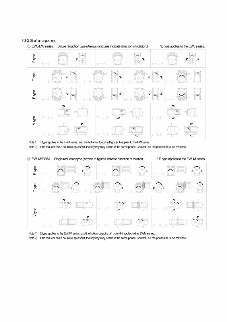
1-3-2. Shaft arrangement
① EWJ/EW series Single reduction type (Arrows in figures indicate direction of rotation.) *E type applies to the EWJ series.
Note 1) E type applies to the EWJ series, and the hollow output shaft type (-H) applies to the EW series.
Note 2) If the reducer has a double output shaft, the keyway may not be in the same phase. Contact us if the phases must be matched.
② EWJM/EWM Single reduction type (Arrows in figures indicate direction of rotation.) * E type applies to the EWJM series.
Note 1) E type applies to the EWJM series, and the hollow output shaft type (-H) applies to the EWM series.
Note 2) If the reducer has a double output shaft, the keyway may not be in the same phase. Contact us if the phases must be matched.
E ty
pe
T ty
pe
V ty
pe
E ty
pe
T ty
pe
B ty
pe
V ty
pe
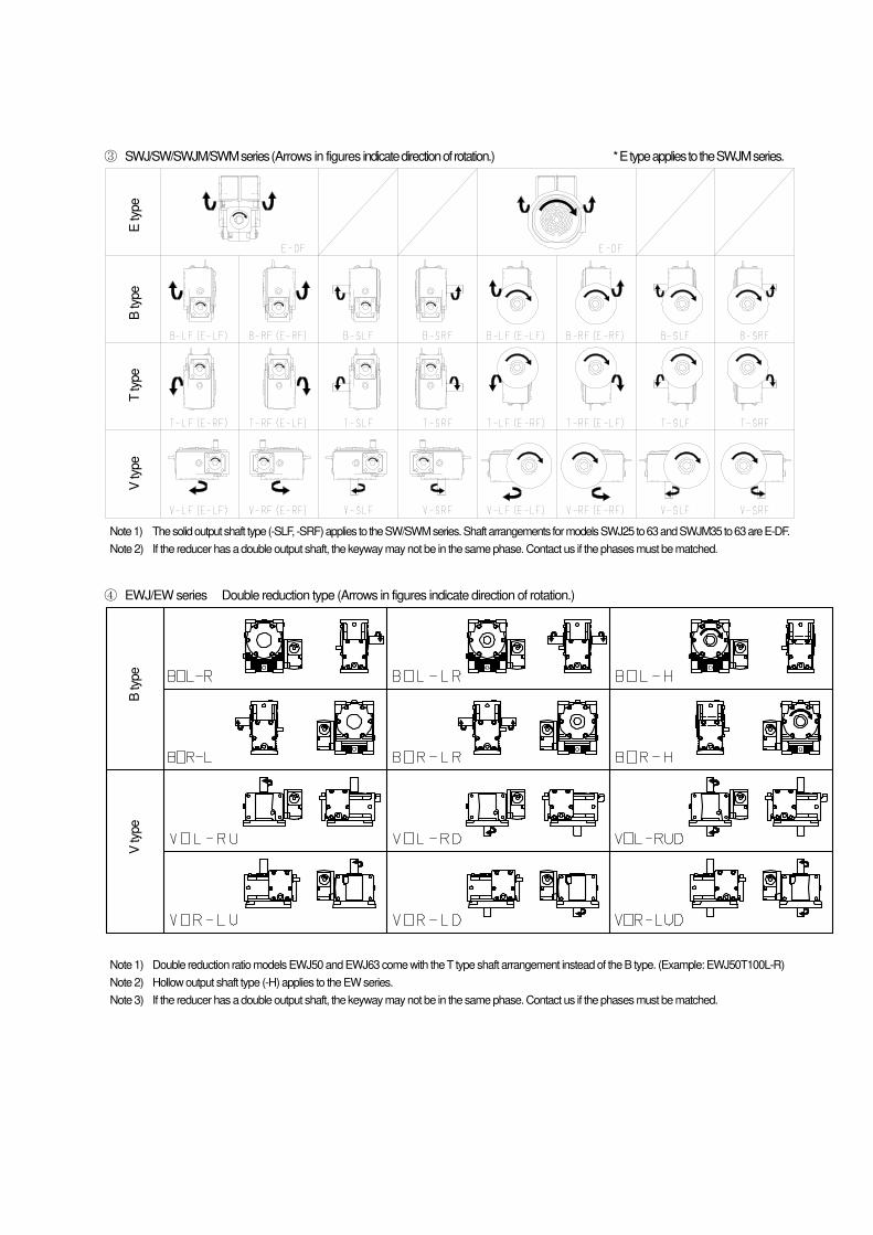
③ SWJ/SW/SWJM/SWM series (Arrows in figures indicate direction of rotation.) * E type applies to the SWJM series.
Note 1) The solid output shaft type (-SLF, -SRF) applies to the SW/SWM series. Shaft arrangements for models SWJ25 to 63 and SWJM35 to 63 are E-DF.
Note 2) If the reducer has a double output shaft, the keyway may not be in the same phase. Contact us if the phases must be matched.
④ EWJ/EW series Double reduction type (Arrows in figures indicate direction of rotation.)
Note 1) Double reduction ratio models EWJ50 and EWJ63 come with the T type shaft arrangement instead of the B type. (Example: EWJ50T100L-R)
Note 2) Hollow output shaft type (-H) applies to the EW series.
Note 3) If the reducer has a double output shaft, the keyway may not be in the same phase. Contact us if the phases must be matched.
E ty
pe
B ty
pe
T ty
pe
V ty
pe
B ty
pe
V ty
pe
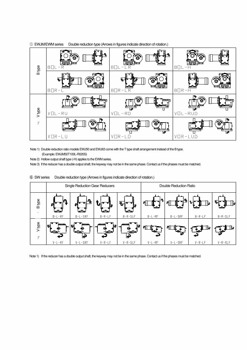
⑤ EWJM/EWM series Double reduction type (Arrows in figures indicate direction of rotation.)
Note 1) Double reduction ratio models EWJ50 and EWJ63 come with the T type shaft arrangement instead of the B type.
(Example: EWJM50T100L-R020S)
Note 2) Hollow output shaft type (-H) applies to the EWM series.
Note 3) If the reducer has a double output shaft, the keyway may not be in the same phase. Contact us if the phases must be matched.
⑥ SW series Double reduction type (Arrows in figures indicate direction of rotation.)
Note 1) If the reducer has a double output shaft, the keyway may not be in the same phase. Contact us if the phases must be matched.
B ty
pe
V ty
pe
Double Reduction Ratio Single Reduction Gear Reducers
B ty
pe
V ty
pe
[ 2 ] Transport
Warning
� Never stand underneath the product while it is being lifted for transport. Falls can result in personal injury.
Caution
(Transport) � Be careful when transporting so as not to drop or overturn the product. Be sure to use lifting hardware when available. Avoid lifting the entire
machine by the lifting hardware after installing the machine. Breaking of the lifting hardware, falls, or overturning can result in injury or equipment damage. Before lifting the reducer, check the load on the nameplate, packaging, external drawing (specification and delivery drawings), or catalog. Do not lift a reducer that exceeds the rated load of the lifting equipment. Breaking of the bolts, falls, or overturning can result in injury or equipment damage.
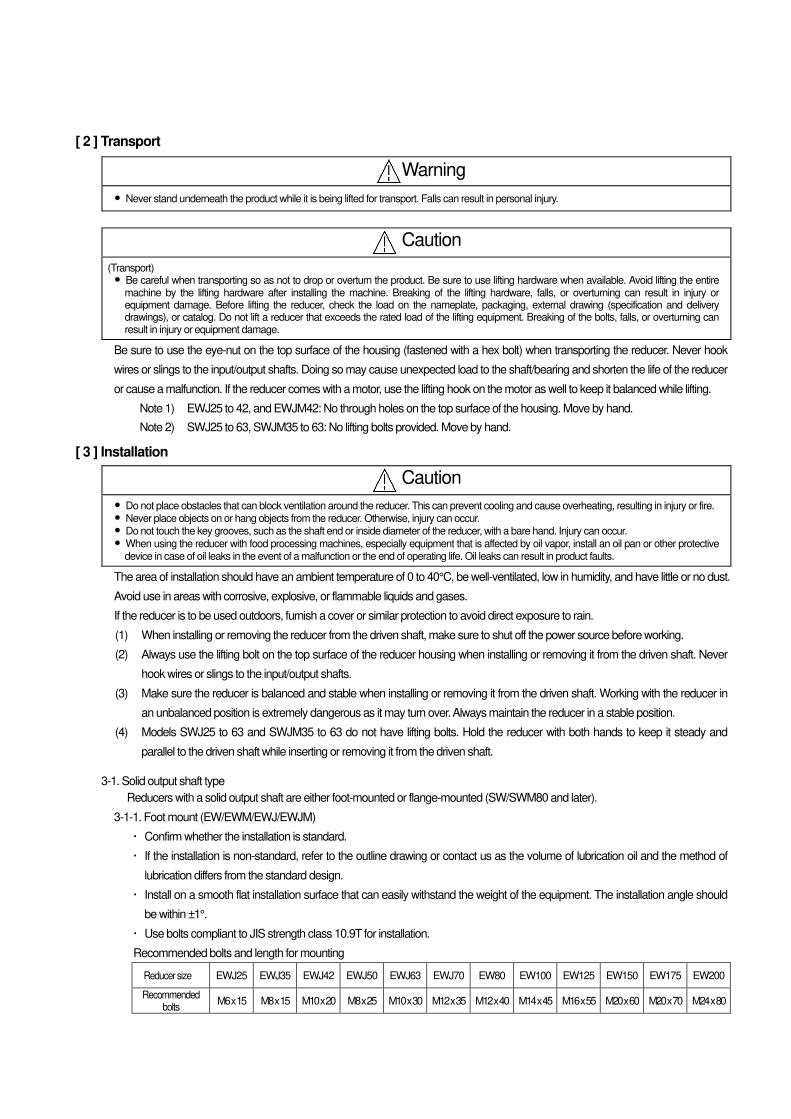
Be sure to use the eye-nut on the top surface of the housing (fastened with a hex bolt) when transporting the reducer. Never hook
wires or slings to the input/output shafts. Doing so may cause unexpected load to the shaft/bearing and shorten the life of the reducer
or cause a malfunction. If the reducer comes with a motor, use the lifting hook on the motor as well to keep it balanced while lifting.
Note 1) EWJ25 to 42, and EWJM42: No through holes on the top surface of the housing. Move by hand.
Note 2) SWJ25 to 63, SWJM35 to 63: No lifting bolts provided. Move by hand.
[ 3 ] Installation
Caution
� Do not place obstacles that can block ventilation around the reducer. This can prevent cooling and cause overheating, resulting in injury or fire. � Never place objects on or hang objects from the reducer. Otherwise, injury can occur. � Do not touch the key grooves, such as the shaft end or inside diameter of the reducer, with a bare hand. Injury can occur. � When using the reducer with food processing machines, especially equipment that is affected by oil vapor, install an oil pan or other protective
device in case of oil leaks in the event of a malfunction or the end of operating life. Oil leaks can result in product faults.
The area of installation should have an ambient temperature of 0 to 40°C, be well-ventilated, low in humidity, and have little or no dust.
Avoid use in areas with corrosive, explosive, or flammable liquids and gases.
If the reducer is to be used outdoors, furnish a cover or similar protection to avoid direct exposure to rain.
(1) When installing or removing the reducer from the driven shaft, make sure to shut off the power source before working.
(2) Always use the lifting bolt on the top surface of the reducer housing when installing or removing it from the driven shaft. Never
hook wires or slings to the input/output shafts.
(3) Make sure the reducer is balanced and stable when installing or removing it from the driven shaft. Working with the reducer in
an unbalanced position is extremely dangerous as it may turn over. Always maintain the reducer in a stable position.
(4) Models SWJ25 to 63 and SWJM35 to 63 do not have lifting bolts. Hold the reducer with both hands to keep it steady and
parallel to the driven shaft while inserting or removing it from the driven shaft.
3-1. Solid output shaft type
Reducers with a solid output shaft are either foot-mounted or flange-mounted (SW/SWM80 and later).
3-1-1. Foot mount (EW/EWM/EWJ/EWJM)
Confirm whether the installation is standard.
If the installation is non-standard, refer to the outline drawing or contact us as the volume of lubrication oil and the method of
lubrication differs from the standard design.
Install on a smooth flat installation surface that can easily withstand the weight of the equipment. The installation angle should
be within ±1°.
Use bolts compliant to JIS strength class 10.9T for installation.
Recommended bolts and length for mounting
Reducer size EWJ25 EWJ35 EWJ42 EWJ50 EWJ63 EWJ70 EW80 EW100 EW125 EW150 EW175 EW200
Recommended bolts
M6 x 15 M8 x 15 M10 x 20 M8 x 25 M10 x 30 M12 x 35 M12 x 40 M14 x 45 M16 x 55 M20 x 60 M20 x 70 M24 x 80
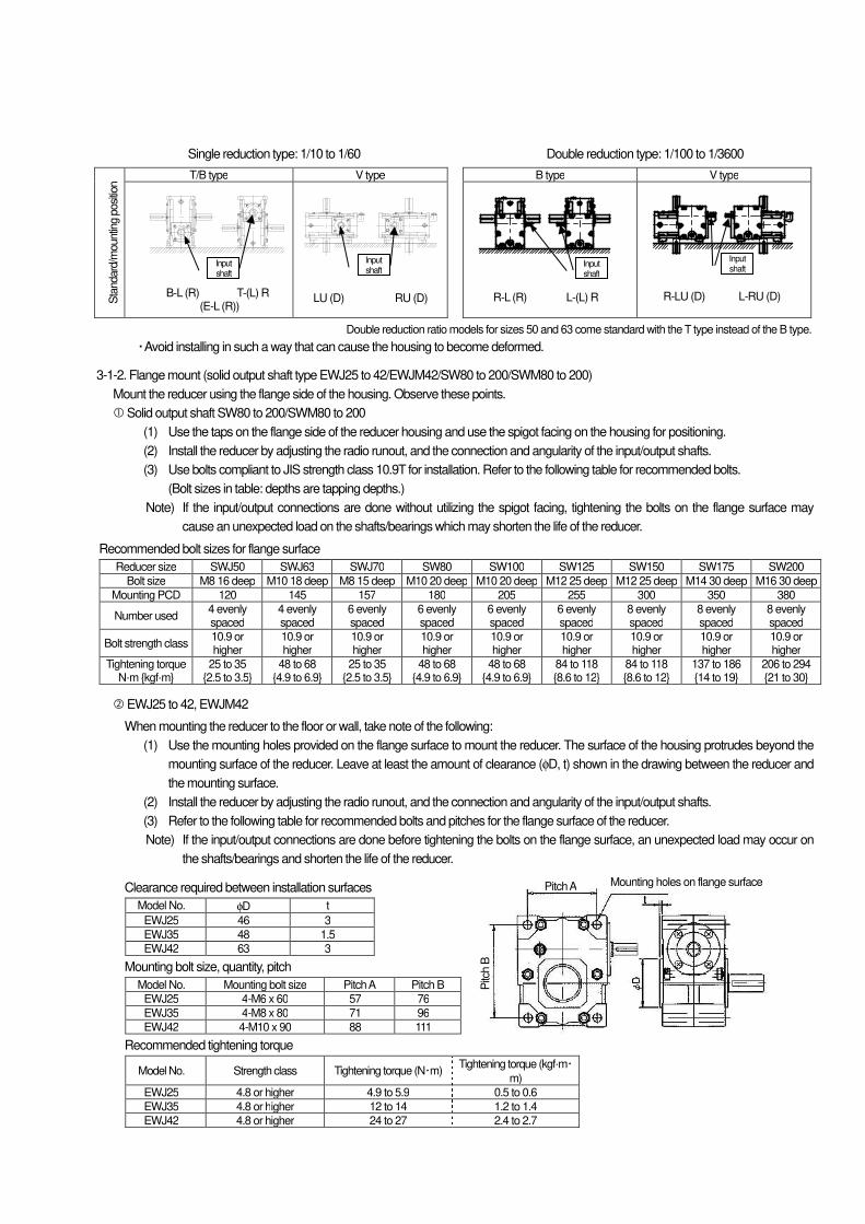
Single reduction type: 1/10 to 1/60 Double reduction type: 1/100 to 1/3600
Sta
ndard
/mountin
g p
osi
tion T/B type V type B type V type
Double reduction ratio models for sizes 50 and 63 come standard with the T type instead of the B type.
Avoid installing in such a way that can cause the housing to become deformed.
3-1-2. Flange mount (solid output shaft type EWJ25 to 42/EWJM42/SW80 to 200/SWM80 to 200)
Mount the reducer using the flange side of the housing. Observe these points.
Solid output shaft SW80 to 200/SWM80 to 200
(1) Use the taps on the flange side of the reducer housing and use the spigot facing on the housing for positioning.
(2) Install the reducer by adjusting the radio runout, and the connection and angularity of the input/output shafts.
(3) Use bolts compliant to JIS strength class 10.9T for installation. Refer to the following table for recommended bolts.
(Bolt sizes in table: depths are tapping depths.)
Note) If the input/output connections are done without utilizing the spigot facing, tightening the bolts on the flange surface may
cause an unexpected load on the shafts/bearings which may shorten the life of the reducer.
Recommended bolt sizes for flange surface
Reducer size SWJ50 SWJ63 SWJ70 SW80 SW100 SW125 SW150 SW175 SW200
Bolt size M8 16 deep M10 18 deep M8 15 deep M10 20 deep M10 20 deep M12 25 deep M12 25 deep M14 30 deep M16 30 deep
Mounting PCD 120 145 157 180 205 255 300 350 380
Number used 4 evenly spaced
4 evenly spaced
6 evenly spaced
6 evenly spaced
6 evenly spaced
6 evenly spaced
8 evenly spaced
8 evenly spaced
8 evenly spaced
Bolt strength class 10.9 or higher
10.9 or higher
10.9 or higher
10.9 or higher
10.9 or higher
10.9 or higher
10.9 or higher
10.9 or higher
10.9 or higher
Tightening torque N·m {kgf·m}
25 to 35 {2.5 to 3.5}
48 to 68 {4.9 to 6.9}
25 to 35 {2.5 to 3.5}
48 to 68 {4.9 to 6.9}
48 to 68 {4.9 to 6.9}
84 to 118 {8.6 to 12}
84 to 118 {8.6 to 12}
137 to 186 {14 to 19}
206 to 294 {21 to 30}
EWJ25 to 42, EWJM42
When mounting the reducer to the floor or wall, take note of the following:
(1) Use the mounting holes provided on the flange surface to mount the reducer. The surface of the housing protrudes beyond the
mounting surface of the reducer. Leave at least the amount of clearance (φD, t) shown in the drawing between the reducer and
the mounting surface.
(2) Install the reducer by adjusting the radio runout, and the connection and angularity of the input/output shafts.
(3) Refer to the following table for recommended bolts and pitches for the flange surface of the reducer.
Note) If the input/output connections are done before tightening the bolts on the flange surface, an unexpected load may occur on
the shafts/bearings and shorten the life of the reducer.
Clearance required between installation surfaces
Model No. φD t
EWJ25 46 3
EWJ35 48 1.5
EWJ42 63 3
Mounting bolt size, quantity, pitch
Model No. Mounting bolt size Pitch A Pitch B
EWJ25 4-M6 x 60 57 76
EWJ35 4-M8 x 80 71 96
EWJ42 4-M10 x 90 88 111
Recommended tightening torque
Model No. Strength class Tightening torque (N・m) Tightening torque (kgf·m・
m)
EWJ25 4.8 or higher 4.9 to 5.9 0.5 to 0.6
EWJ35 4.8 or higher 12 to 14 1.2 to 1.4
EWJ42 4.8 or higher 24 to 27 2.4 to 2.7
Input shaft
Input shaft
Input shaft
Input shaft
R-L (R) L-(L) R R-LU (D) L-RU (D) LU (D) RU (D) B-L (R) T-(L) R (E-L (R))
Pitch A Mounting holes on flange surface
Pitc
h B

3-2. Hollow output shaft type
There are three ways to prevent the reducer from rotating: torque arm mount, flange mount, and foot mount (EW-H only).
(1) Before inserting the driven shaft into the hollow output shaft, make sure the outside of the driven shaft and the inside of the hollow shaft
are free of scratches and dust.
(2) To make insertion easier, apply grease or molybdenum disulfide to the driven shaft.
(3) If the shafts fit very tightly, help the hollow shaft slide smoothly by tapping its opposite end with a plastic hammer. When you do this, be
careful not to damage the oil seal.
(4) The hollow shaft keyway is finished to New JIS standards for normal grade keyways. As for key length, refer to the following table,
Recommended driven shaft lengths.
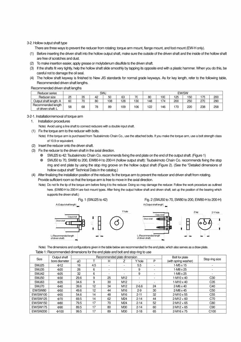
Recommended driven shaft lengths
Reducer series SWJ EW/SW
Reducer size 25 35 42 50 63 70 80 100 125 150 175 200
Output shaft length: A 60 70 80 108 128 130 148 174 200 250 270 290
Recommended length of driven shaft: L
58 68 78 89 109 106 122 146 170 220 238 258
3-2-1. Installation/removal of torque arm
1. Installation procedures
Note) Avoid using a line shaft to connect reducers with a double input shaft.
(1) Fix the torque arm to the reducer with bolts.
Note) If the torque arm is purchased from Tsubakimoto Chain Co., use the attached bolts. If you make the torque arm, use a bolt strength class
of 10.9 or equivalent.
(2) Insert the reducer onto the driven shaft.
(3) Fix the reducer to the driven shaft in the axial direction.
SWJ25 to 42: Tsubakimoto Chain Co. recommends fixing the end plate on the end of the output shaft. (Figure 1)
SWJ50 to 70, SW80 to 200, EW80-H to 200-H (hollow output shaft): Tsubakimoto Chain Co. recommends fixing the stop
ring and end plate by using the stop ring groove on the hollow output shaft (Figure 2). (See the "Detailed dimensions of
hollow output shaft" Technical Data in the catalog.)
(4) After finalizing the installation position of the reducer, fix the torque arm to prevent the reducer and driven shaft from rotating.
Provide sufficient room so that the torque arm is free to move in the axial direction.
Note) Do not fix the tip of the torque arm before fixing it to the reducer. Doing so may damage the reducer. Follow the work procedure as outlined
here. (EW80-H to 200-H are foot mount types. After fixing the output hollow shaft and driven shaft, set up the position of the bearing which
supports the driven shaft.)
Fig. 1 (SWJ25 to 42) Fig. 2 (SWJ50 to 70, SW80 to 200, EW80-H to 200-H)
Note) The dimensions and configurations given in the table below are recommended for the end plate, which also serves as a draw plate.
Table 1: Recommended dimensions for the end plate and bolt and stop ring to use
Size Output shaft
bore diameter
Recommended plate dimension Bolt for plate (with spring washer)
Stop ring size φD T H Z Y hole P
SWJ25 Φ12 16 4.5 - - 5.5 - 1-M5 x 15 -
SWJ35 Φ20 26 6 - - 9 - 1-M8 x 25 -
SWJ42 Φ25 32 6 - - 9 - 1-M8 x 25 -
SWJ50 Φ30 29.6 9 25 M12 - - 1-M10 x 40 C30
SWJ63 Φ35 34.6 9 30 M12 - - 1-M10 x 40 C35
SWJ70 Φ40 39.6 12 34 M12 2-6.6 24 2-M6 x 40 C40
EW/SW80 Φ50 49.6 12 44 M16 2-9 30 2-M8 x 45 C50
EW/SW100 Φ55 54.6 14 48 M16 2-11 32 2-M10 x 55 C55
EW/SW125 Φ70 69.5 14 62 M24 2-14 44 2-M12 × 60 C70
EW/SW150 Φ80 79.5 17 70 M24 2-14 52 2-M12 × 65 C80
EW/SW175 Φ90 89.5 17 80 M30 2-14 60 2-M12 × 65 C90
EW/SW200 Φ100 99.5 17 89 M30 2-18 65 2-M16 x 75 C100
A (Output shaft length)
Output shaft
Driven shaft
L (Recommended length of driven shaft)
A (Output shaft length)
Output shaft
Driven shaft
L (Recommended length of driven shaft)
Y hole Z tap 2-Y hole
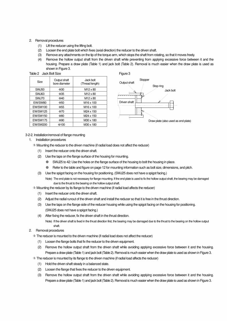
2. Removal procedures
(1) Lift the reducer using the lifting bolt.
(2) Loosen the end plate bolt which fixes (axial direction) the reducer to the driven shaft.
(3) Remove any attachments on the tip of the torque arm, which stops the shaft from rotating, so that it moves freely.
(4) Remove the hollow output shaft from the driven shaft while preventing from applying excessive force between it and the
housing. Prepare a draw plate (Table 1) and jack bolt (Table 2). Removal is much easier when the draw plate is used as
shown in Figure 3.
Table 2 Jack Bolt Size Figure 3
Size Output shaft
bore diameter Jack bolt
(Thread length)
SWJ50 Φ30 M12 x 80
SWJ63 Φ35 M12 x 80
SWJ70 Φ40 M12 x 80
EW/SW80 Φ50 M16 x 100
EW/SW100 Φ55 M16 x 100
EW/SW125 Φ70 M24 x 150
EW/SW150 Φ80 M24 x 150
EW/SW175 Φ90 M30 x 180
EW/SW200 Φ100 M30 x 180
3-2-2. Installation/removal of flange mounting
1. Installation procedures
Mounting the reducer to the driven machine (if radial load does not affect the reducer)
(1) Insert the reducer onto the driven shaft.
(2) Use the taps on the flange surface of the housing for mounting.
SWJ25 to 42: Use the holes on the flange surface of the housing to bolt the housing in place.
Refer to the table and figure on page 12 for mounting information such as bolt size, dimensions, and pitch.
(3) Use the spigot facing on the housing for positioning. (SWJ25 does not have a spigot facing.)
Note) The end plate is not necessary for flange mounting. If the end plate is used to fix the hollow output shaft, the bearing may be damaged
due to the thrust to the bearing on the hollow output shaft.
Mounting the reducer by its flange to the driven machine (if radial load affects the reducer)
(1) Insert the reducer onto the driven shaft.
(2) Adjust the radial runout of the driven shaft and install the reducer so that it is free in the thrust direction.
(3) Use the taps on the flange side of the reducer housing while using the spigot facing on the housing for positioning.
(SWJ25 does not have a spigot facing.)
(4) After fixing the reducer, fix the driven shaft in the thrust direction.
Note) If the driven shaft is fixed in the thrust direction first, the bearing may be damaged due to the thrust to the bearing on the hollow output
shaft.
2. Removal procedures
The reducer is mounted to the driven machine (if radial load does not affect the reducer)
(1) Loosen the flange bolts that fix the reducer to the driven equipment.
(2) Remove the hollow output shaft from the driven shaft while avoiding applying excessive force between it and the housing.
Prepare a draw plate (Table 1) and jack bolt (Table 2). Removal is much easier when the draw plate is used as shown in Figure 3.
The reducer is mounted by its flange to the driven machine (if radial load affects the reducer)
(1) Hold the driven shaft steady in a balanced state.
(2) Loosen the flange that fixes the reducer to the driven equipment.
(3) Remove the hollow output shaft from the driven shaft while avoiding applying excessive force between it and the housing.
Prepare a draw plate (Table 1) and jack bolt (Table 2). Removal is much easier when the draw plate is used as shown in Figure 3.
Output shaft Stopper
Stop ring
Jack bolt
Draw plate (also used as end plate)
Driven shaft
3-2-3. Installation/removal of foot mounting (EW-H hollow output shaft)
Make sure the driven machine and reducer are aligned properly by referring to these installation procedures: Section 3-1-1. Foot
mount; Section 3-1-2. Flange mount; Section 3-2-1. Installation/removal of torque arm. Improper alignment can cause unexpected
loads which may lead to breakage of the shaft/bearing.
[ 4 ] Connection
Caution
� When connecting the reducer to the motor and load, be careful of the alignment, belt tension, and parallelism of the pulley. When direct coupling, be careful of the direct coupling accuracy. When setting a belt, adjust the belt tension correctly. Before operation, securely tighten the pulley and coupling tightening bolts. Otherwise, launching of parts can cause injury or equipment damage.
� Provide a cover so that rotating parts cannot be touched. Otherwise, injury can occur. � When rotating the reducer separately, remove the key temporarily attached to the output shaft. Otherwise, injury can
occur. � Check the direction of rotation before connecting to another machine. A difference in direction can result in injury or
equipment damage.
4-1. Verifying the direction of rotation
Worms are always cut to a right-handed helix. Verify the rotational direction of the input and output shafts.
4-2. Connection
(1) Connecting to the input shaft and output shaft of the reducer
• Do not apply impact or excessive thrust loads to the shaft when installing pulleys, sprockets, or couplings to the reducer
input/output shafts.
• Align accurately. Refer to pulley, sprocket, or coupling catalogs/manuals to ensure alignment accuracy.
• Shaft eccentricity, and radial and axial loads that exceed allowable values may cause vibration or noise, possibly shortening gear,
bearing, and shaft life.
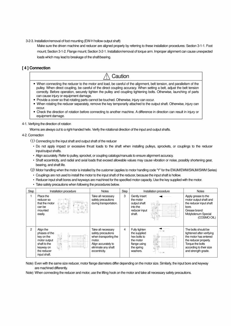
(2) Motor handling when the motor is installed by the customer (applies to motor handling code “Y” for the EWJM/EWM/SWJM/SWM Series)
• Couplings are not used to install the motor to the input shaft of the reducer, because the input shaft is hollow.
• Reducer input shaft bores and keyways are machined for the specified motor capacity. Use the key supplied with the motor.
• Take safety precautions when following the procedures below.
Step Installation procedure Notes Step Installation procedure Notes
1 Place the reducer so that the motor can be mounted easily.
Take all necessary safety precautions during transportation.
3
Gently insert the motor output shaft into the reducer input shaft.
Apply grease to the motor output shaft and the reducer input shaft bore. Grease brand: Molybdenum Special
(COSMO OIL)
2 Align the phases of the key on the motor output shaft to the keyway on the reducer input shaft.
Take all necessary safety precautions when transporting the motor. Align accurately to eliminate any shaft eccentricity.
4 Fully tighten the supplied hex bolts to the motor flange using the spring washers.
The bolts should be tightened after verifying the motor has entered the reducer properly. Torque the bolts according to their size and strength grade.
Note) Even with the same size reducer, motor flange diameters differ depending on the motor size. Similarly, the input bore and keyway
are machined differently.
Note) When connecting the reducer and motor, use the lifting hook on the motor and take all necessary safety precautions.
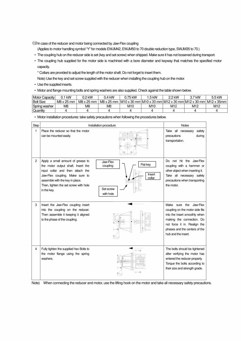
(3) In case of the reducer and motor being connected by Jaw-Flex coupling
(Applies to motor handling symbol “Y” for models EWJM42, EWJM50 to 70 double reduction type, SWJM35 to 70.)
• The coupling hub on the reducer side is set (key and set screw) when shipped. Make sure it has not loosened during transport.
• The coupling hub supplied for the motor side is machined with a bore diameter and keyway that matches the specified motor
capacity.
* Collars are provided to adjust the length of the motor shaft. Do not forget to insert them.
Note) Use the key and set screw supplied with the reducer when installing the coupling hub on the motor.
• Use the supplied inserts.
• Motor and flange mounting bolts and spring washers are also supplied. Check against the table shown below.
Motor Capacity 0.1 kW 0.2 kW 0.4 kW 0.75 kW 1.5 kW 2.2 kW 3.7 kW 5.5 kW
Bolt Size M8 x 25 mm M8 x 25 mm M8 x 25 mm M10 x 30 mm M10 x 30 mm M12 x 30 mm M12 x 30 mm M12 x 35mm
Spring washer M8 M8 M8 M10 M10 M12 M12 M12
Quantity 4 4 4 4 4 4 4 4
• Motor installation procedures: take safety precautions when following the procedures below.
Step Installation procedure Notes
1 Place the reducer so that the motor
can be mounted easily.
Take all necessary safety
precautions during
transportation.
2 Apply a small amount of grease to
the motor output shaft. Insert the
input collar and then attach the
Jaw-Flex coupling. Make sure to
assemble with the key in place.
Then, tighten the set screw with hole
in the key.
Do not hit the Jaw-Flex
coupling with a hammer or
other object when inserting it.
Take all necessary safety
precautions when transporting
the motor.
3 Insert the Jaw-Flex coupling insert
into the coupling on the reducer.
Then assemble it keeping it aligned
to the phase of the coupling.
Make sure the Jaw-Flex
coupling on the motor side fits
into the insert smoothly when
making the connection. Do
not force it in. Realign the
phases and the centers of the
hub and the insert.
4 Fully tighten the supplied hex Bolts to
the motor flange using the spring
washers.
The bolts should be tightened
after verifying the motor has
entered the reducer properly.
Torque the bolts according to
their size and strength grade.
Note) When connecting the reducer and motor, use the lifting hook on the motor and take all necessary safety precautions.
Insert collar
Flat key Jaw-Flex coupling
Set screw
with hole
[ 5 ] Lubrication
Worm gear reducers are filled with lubrication oil and sealed before shipment. They can be used as is without having to add oil.
5-1.Recommended lubrication oil Daphne Alpha Oil TE260 (IDEMITSU)
• Lubrication oil is vital to reducer capacity, life, and efficiency. Use only lubrication oil recommended by Tsubakimoto Chain Co.
.Do not mix the oil with other brands.
• Daphne Alpha Oil TE150 is recommended for reducers that have trouble starting in low temperature environments with an input
speed of 1500 r/min or faster.
• Do not mix with other lubrication oil. This can result in reduced performance and shortened operating life.
• Single reduction gear reducers running at an input speed of 500 r/min or slower can benefit from longer life by switching to Daphne
Alpha Oil TE380.
• Do not change the brand of lubrication oil. Contact your distributor or Tsubakimoto Chain Co. to have the lubrication oil changed.
• Contact your distributor or Tsubakimoto Chain Co. dealer for information about Daphne Alpha Oil TE.
Note) Contact us if the ambient temperature is below -10°C or above 50°C.
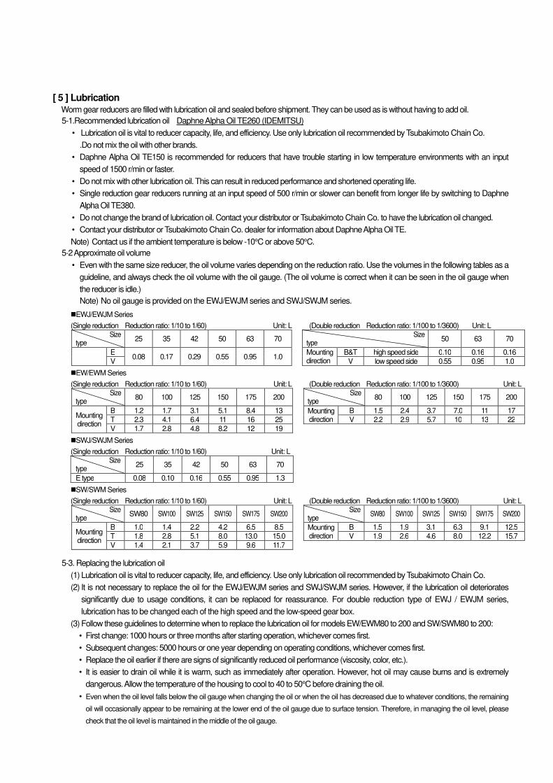
5-2 Approximate oil volume
• Even with the same size reducer, the oil volume varies depending on the reduction ratio. Use the volumes in the following tables as a
guideline, and always check the oil volume with the oil gauge. (The oil volume is correct when it can be seen in the oil gauge when
the reducer is idle.)
Note) No oil gauge is provided on the EWJ/EWJM series and SWJ/SWJM series.
EWJ/EWJM Series
(Single reduction Reduction ratio: 1/10 to 1/60) Unit: L (Double reduction Reduction ratio: 1/100 to 1/3600) Unit: L Size
type 25 35 42 50 63 70
Size type
50 63 70
E 0.08 0.17 0.29 0.55 0.95 1.0
Mounting direction
B&T high speed side 0.10 0.16 0.16
V V low speed side 0.55 0.95 1.0 EW/EWM Series
(Single reduction Reduction ratio: 1/10 to 1/60) Unit: L (Double reduction Reduction ratio: 1/100 to 1/3600) Unit: L Size
type 80 100 125 150 175 200
Size type
80 100 125 150 175 200
Mounting direction
B 1.2 1.7 3.1 5.1 8.4 13 Mounting direction
B 1.5 2.4 3.7 7.0 11 17
T 2.3 4.1 6.4 11 16 25 V 2.2 2.9 5.7 10 13 22
V 1.7 2.8 4.8 8.2 12 19
SWJ/SWJM Series
(Single reduction Reduction ratio: 1/10 to 1/60) Unit: L Size
type 25 35 42 50 63 70
E type 0.08 0.10 0.16 0.55 0.95 1.3
SW/SWM Series
(Single reduction Reduction ratio: 1/10 to 1/60) Unit: L (Double reduction Reduction ratio: 1/100 to 1/3600) Unit: L Size
type SW80 SW100 SW125 SW150 SW175 SW200
Size type
SW80 SW100 SW125 SW150 SW175 SW200
Mounting direction
B 1.0 1.4 2.2 4.2 6.5 8.5 Mounting direction
B 1.5 1.9 3.1 6.3 9.1 12.5
T 1.8 2.8 5.1 8.0 13.0 15.0 V 1.9 2.6 4.6 8.0 12.2 15.7
V 1.4 2.1 3.7 5.9 9.6 11.7
5-3. Replacing the lubrication oil
(1) Lubrication oil is vital to reducer capacity, life, and efficiency. Use only lubrication oil recommended by Tsubakimoto Chain Co.
(2) It is not necessary to replace the oil for the EWJ/EWJM series and SWJ/SWJM series. However, if the lubrication oil deteriorates
significantly due to usage conditions, it can be replaced for reassurance. For double reduction type of EWJ / EWJM series,
lubrication has to be changed each of the high speed and the low-speed gear box.
(3) Follow these guidelines to determine when to replace the lubrication oil for models EW/EWM80 to 200 and SW/SWM80 to 200:
• First change: 1000 hours or three months after starting operation, whichever comes first.
• Subsequent changes: 5000 hours or one year depending on operating conditions, whichever comes first.
• Replace the oil earlier if there are signs of significantly reduced oil performance (viscosity, color, etc.).
• It is easier to drain oil while it is warm, such as immediately after operation. However, hot oil may cause burns and is extremely
dangerous. Allow the temperature of the housing to cool to 40 to 50°C before draining the oil.
• Even when the oil level falls below the oil gauge when changing the oil or when the oil has decreased due to whatever conditions, the remaining
oil will occasionally appear to be remaining at the lower end of the oil gauge due to surface tension. Therefore, in managing the oil level, please
check that the oil level is maintained in the middle of the oil gauge.
• Tsubakimoto Chain Co. recommends flushing the inside of the housing with the new oil.
Note) Do not mix the oil with other brands.
Note) No oil gauge is provided on the EWJ/EWJM series and SWJ/SWJM series.
5-4. Supplying grease (Semi-standard package)
• If the mounting direction of the reducer causes the shaft bearing to be face up (where the bearing is located above the oil level), the
bearing must be greased periodically. (Applicable to sizes 80 and above, excludes sizes 70 and below.)
• Models that must be greased are provided with a tapped hole for mounting a grease nipple. (This is indicated on the external drawings (specification and delivery diagrams) as a grease nipple. See the external drawings
(specification and delivery drawings)).
• A stopper plug (M6 fine threaded hex bolt) is mounted before shipment to prevent oil leakage during transport. Replace it with the
grease nipple supplied with the reducer during installation or before operating. Note, the bearings are greased before shipment.
• Follow the procedures outlined below to supply grease every 1000 hours of operation. Greasing has to be done on installation,
before initial drive and every 1000 hours.
•
Step Replacement procedures
1 Add grease when the machine is stopped.
2 Supply grease from the grease nipple located on the top of the housing. Use only the recommended grease. Note) Do not over grease. Doing so may cause the reducer to heat up and cause the lubrication oil to deteriorate prematurely.
Grease nipple size: A-M6F
5-4-1. Recommended grease (standard package ambient temperature: -10°C to 40°C) Manufacturer Brand (industrial all-purpose grease JIS grade 2)
EMG Lubricants Mobilux EP2 (factory filled)
Idemitsu Daphne Eponex No. 2
Note) A different brand of grease may be used for special packages (high temperature, freezing, etc.) Always supply with the type of lubricant appropriate for the specifications. Also take note of any precautions documented on the external diagrams (specification and delivery diagrams).
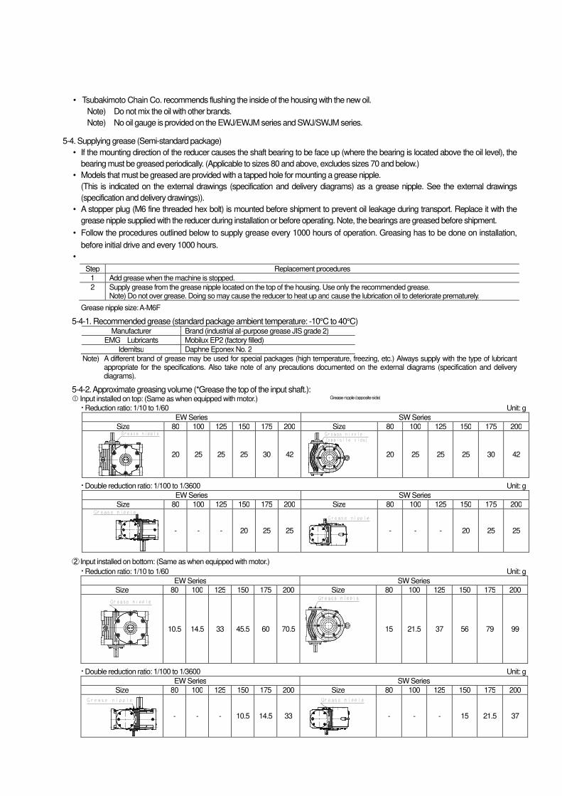
5-4-2. Approximate greasing volume (*Grease the top of the input shaft.): Input installed on top: (Same as when equipped with motor.)
Reduction ratio: 1/10 to 1/60 Unit: g
EW Series SW Series
Size 80 100 125 150 175 200 Size 80 100 125 150 175 200
20 25 25 25 30 42
20 25 25 25 30 42
Double reduction ratio: 1/100 to 1/3600 Unit: g
EW Series SW Series
Size 80 100 125 150 175 200 Size 80 100 125 150 175 200
- - - 20 25 25
- - - 20 25 25
② Input installed on bottom: (Same as when equipped with motor.)
Reduction ratio: 1/10 to 1/60 Unit: g
EW Series SW Series
Size 80 100 125 150 175 200 Size 80 100 125 150 175 200
10.5 14.5 33 45.5 60 70.5
15 21.5 37 56 79 99
Double reduction ratio: 1/100 to 1/3600 Unit: g
EW Series SW Series
Size 80 100 125 150 175 200 Size 80 100 125 150 175 200
- - - 10.5 14.5 33
- - - 15 21.5 37
Grease nipple (opposite side)
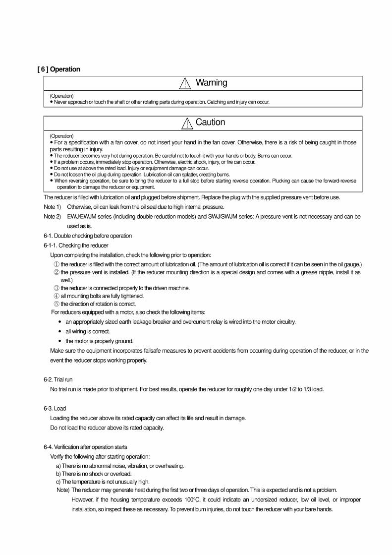
[ 6 ] Operation
Warning
(Operation) � Never approach or touch the shaft or other rotating parts during operation. Catching and injury can occur.
Caution
(Operation)
� For a specification with a fan cover, do not insert your hand in the fan cover. Otherwise, there is a risk of being caught in those parts resulting in injury. � The reducer becomes very hot during operation. Be careful not to touch it with your hands or body. Burns can occur. � If a problem occurs, immediately stop operation. Otherwise, electric shock, injury, or fire can occur. � Do not use at above the rated load. Injury or equipment damage can occur. � Do not loosen the oil plug during operation. Lubrication oil can splatter, creating burns. � When reversing operation, be sure to bring the reducer to a full stop before starting reverse operation. Plucking can cause the forward-reverse
operation to damage the reducer or equipment.
The reducer is filled with lubrication oil and plugged before shipment. Replace the plug with the supplied pressure vent before use.
Note 1) Otherwise, oil can leak from the oil seal due to high internal pressure.
Note 2) EWJ/EWJM series (including double reduction models) and SWJ/SWJM series: A pressure vent is not necessary and can be
used as is.
6-1. Double checking before operation
6-1-1. Checking the reducer
Upon completing the installation, check the following prior to operation:
① the reducer is filled with the correct amount of lubrication oil. (The amount of lubrication oil is correct if it can be seen in the oil gauge.)
② the pressure vent is installed. (If the reducer mounting direction is a special design and comes with a grease nipple, install it as
well.)
③ the reducer is connected properly to the driven machine.
④ all mounting bolts are fully tightened.
⑤ the direction of rotation is correct.
For reducers equipped with a motor, also check the following items:
� an appropriately sized earth leakage breaker and overcurrent relay is wired into the motor circuitry.
� all wiring is correct.
� the motor is properly ground.
Make sure the equipment incorporates failsafe measures to prevent accidents from occurring during operation of the reducer, or in the
event the reducer stops working properly.
6-2. Trial run
No trial run is made prior to shipment. For best results, operate the reducer for roughly one day under 1/2 to 1/3 load.
6-3. Load
Loading the reducer above its rated capacity can affect its life and result in damage.
Do not load the reducer above its rated capacity.
6-4. Verification after operation starts
Verify the following after starting operation:
a) There is no abnormal noise, vibration, or overheating.
b) There is no shock or overload.
c) The temperature is not unusually high.
Note) The reducer may generate heat during the first two or three days of operation. This is expected and is not a problem.
However, if the housing temperature exceeds 100°C, it could indicate an undersized reducer, low oil level, or improper
installation, so inspect these as necessary. To prevent burn injuries, do not touch the reducer with your bare hands.
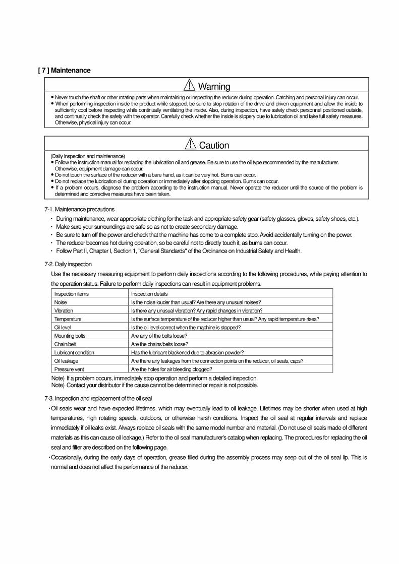
[ 7 ] Maintenance
Warning
� Never touch the shaft or other rotating parts when maintaining or inspecting the reducer during operation. Catching and personal injury can occur. � When performing inspection inside the product while stopped, be sure to stop rotation of the drive and driven equipment and allow the inside to
sufficiently cool before inspecting while continually ventilating the inside. Also, during inspection, have safety check personnel positioned outside, and continually check the safety with the operator. Carefully check whether the inside is slippery due to lubrication oil and take full safety measures. Otherwise, physical injury can occur.
Caution
(Daily inspection and maintenance) � Follow the instruction manual for replacing the lubrication oil and grease. Be sure to use the oil type recommended by the manufacturer.
Otherwise, equipment damage can occur. � Do not touch the surface of the reducer with a bare hand, as it can be very hot. Burns can occur. � Do not replace the lubrication oil during operation or immediately after stopping operation. Burns can occur. � If a problem occurs, diagnose the problem according to the instruction manual. Never operate the reducer until the source of the problem is
determined and corrective measures have been taken.
7-1. Maintenance precautions
・ During maintenance, wear appropriate clothing for the task and appropriate safety gear (safety glasses, gloves, safety shoes, etc.).
・ Make sure your surroundings are safe so as not to create secondary damage.
・ Be sure to turn off the power and check that the machine has come to a complete stop. Avoid accidentally turning on the power.
・ The reducer becomes hot during operation, so be careful not to directly touch it, as burns can occur.
・ Follow Part II, Chapter I, Section 1, "General Standards" of the Ordinance on Industrial Safety and Health.
7-2. Daily inspection
Use the necessary measuring equipment to perform daily inspections according to the following procedures, while paying attention to
the operation status. Failure to perform daily inspections can result in equipment problems.
Inspection items Inspection details
Noise Is the noise louder than usual? Are there any unusual noises?
Vibration Is there any unusual vibration? Any rapid changes in vibration?
Temperature Is the surface temperature of the reducer higher than usual? Any rapid temperature rises?
Oil level Is the oil level correct when the machine is stopped?
Mounting bolts Are any of the bolts loose?
Chain/belt Are the chains/belts loose?
Lubricant condition Has the lubricant blackened due to abrasion powder?
Oil leakage Are there any leakages from the connection points on the reducer, oil seals, caps?
Pressure vent Are the holes for air bleeding clogged?
Note) If a problem occurs, immediately stop operation and perform a detailed inspection. Note) Contact your distributor if the cause cannot be determined or repair is not possible.
7-3. Inspection and replacement of the oil seal
・ Oil seals wear and have expected lifetimes, which may eventually lead to oil leakage. Lifetimes may be shorter when used at high
temperatures, high rotating speeds, outdoors, or otherwise harsh conditions. Inspect the oil seal at regular intervals and replace
immediately if oil leaks exist. Always replace oil seals with the same model number and material. (Do not use oil seals made of different
materials as this can cause oil leakage.) Refer to the oil seal manufacturer's catalog when replacing. The procedures for replacing the oil
seal and filter are described on the following page.
・ Occasionally, during the early days of operation, grease filled during the assembly process may seep out of the oil seal lip. This is
normal and does not affect the performance of the reducer.
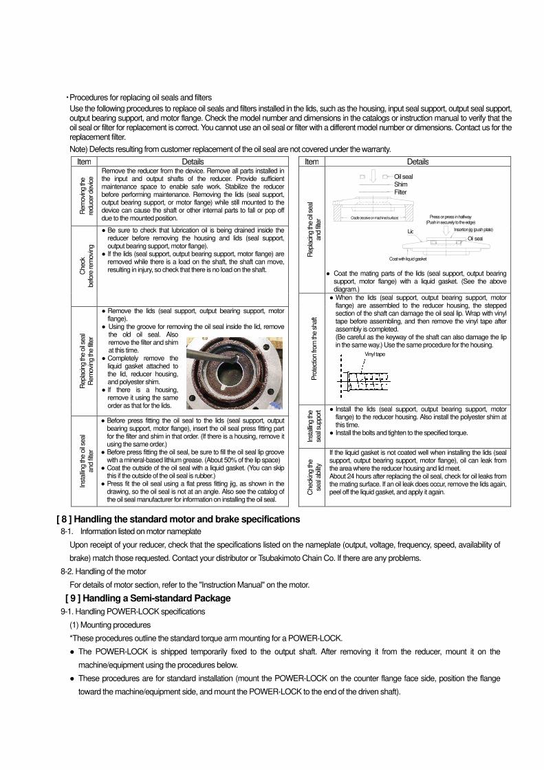
・ Procedures for replacing oil seals and filters
Use the following procedures to replace oil seals and filters installed in the lids, such as the housing, input seal support, output seal support, output bearing support, and motor flange. Check the model number and dimensions in the catalogs or instruction manual to verify that the oil seal or filter for replacement is correct. You cannot use an oil seal or filter with a different model number or dimensions. Contact us for the replacement filter.
Note) Defects resulting from customer replacement of the oil seal are not covered under the warranty.
Item Details Item Details
Rem
ovi
ng th
e
reduce
r devi
ce
Remove the reducer from the device. Remove all parts installed in the input and output shafts of the reducer. Provide sufficient maintenance space to enable safe work. Stabilize the reducer before performing maintenance. Removing the lids (seal support, output bearing support, or motor flange) while still mounted to the device can cause the shaft or other internal parts to fall or pop off due to the mounted position.
Repla
cing th
e o
il se
al
and fi
lter
● Coat the mating parts of the lids (seal support, output bearing support, motor flange) with a liquid gasket. (See the above diagram.)
Check
befo
re re
movi
ng
● Be sure to check that lubrication oil is being drained inside the reducer before removing the housing and lids (seal support, output bearing support, motor flange).
● If the lids (seal support, output bearing support, motor flange) are removed while there is a load on the shaft, the shaft can move, resulting in injury, so check that there is no load on the shaft.
Pro
tect
ion fr
om
the s
haft
● When the lids (seal support, output bearing support, motor flange) are assembled to the reducer housing, the stepped section of the shaft can damage the oil seal lip. Wrap with vinyl tape before assembling, and then remove the vinyl tape after assembly is completed. (Be careful as the keyway of the shaft can also damage the lip in the same way.) Use the same procedure for the housing.
Repla
cing th
e o
il se
al
Rem
ovi
ng th
e fi
lter
● Remove the lids (seal support, output bearing support, motor flange).
● Using the groove for removing the oil seal inside the lid, remove the old oil seal. Also remove the filter and shim at this time.
● Completely remove the liquid gasket attached to the lid, reducer housing, and polyester shim.
● If there is a housing, remove it using the same order as that for the lids.
Inst
allin
g th
e
seal s
upport ● Install the lids (seal support, output bearing support, motor
flange) to the reducer housing. Also install the polyester shim at this time.
● Install the bolts and tighten to the specified torque.
Inst
alling th
e o
il se
al
and fi
lter
● Before press fitting the oil seal to the lids (seal support, output bearing support, motor flange), insert the oil seal press fitting part for the filter and shim in that order. (If there is a housing, remove it using the same order.)
● Before press fitting the oil seal, be sure to fill the oil seal lip groove with a mineral-based lithium grease. (About 50% of the lip space)
● Coat the outside of the oil seal with a liquid gasket. (You can skip this if the outside of the oil seal is rubber.)
● Press fit the oil seal using a flat press fitting jig, as shown in the drawing, so the oil seal is not at an angle. Also see the catalog of the oil seal manufacturer for information on installing the oil seal.
Check
ing th
e
seal a
bility
If the liquid gasket is not coated well when installing the lids (seal support, output bearing support, motor flange), oil can leak from the area where the reducer housing and lid meet. About 24 hours after replacing the oil seal, check for oil leaks from the mating surface. If an oil leak does occur, remove the lids again, peel off the liquid gasket, and apply it again.
[ 8 ] Handling the standard motor and brake specifications
8-1. Information listed on motor nameplate
Upon receipt of your reducer, check that the specifications listed on the nameplate (output, voltage, frequency, speed, availability of
brake) match those requested. Contact your distributor or Tsubakimoto Chain Co. If there are any problems.
8-2. Handling of the motor
For details of motor section, refer to the "Instruction Manual" on the motor.
[ 9 ] Handling a Semi-standard Package
9-1. Handling POWER-LOCK specifications
(1) Mounting procedures
*These procedures outline the standard torque arm mounting for a POWER-LOCK.
● The POWER-LOCK is shipped temporarily fixed to the output shaft. After removing it from the reducer, mount it on the
machine/equipment using the procedures below.
● These procedures are for standard installation (mount the POWER-LOCK on the counter flange face side, position the flange
toward the machine/equipment side, and mount the POWER-LOCK to the end of the driven shaft).
Vinyl tape
Press or press in halfway
(Push in securely to the edge)
Insertion jig (push plate)
Oil seal
Coat with liquid gasket
Lid
Shim
Filter
Oil seal
Cradle (receive on machined surface)
● Recommended tolerance for driven shaft diameter: h6
1) Make sure there are no scratches or dust on the periphery of the driven shaft (recommended tolerance: h6), and the inside of
the hollow output shaft of the reducer. Using the lifting bolt on the top surface of the reducer, suspend the reducer and insert it
into the driven shaft.
2) Thoroughly clean all dust and oil from the periphery of the output shaft of the reducer and inner shaft of the POWER-LOCK
with a rag. Lightly push the POWER-LOCK onto the periphery of the reducer output shaft.
Note) If the POWER-LOCK is too heavy, disassemble it and reassemble it on the output shaft.
Note) The bolts and main unit of the POWER-LOCK SL Series are coated with a special lubricant and require no further
lubrication.
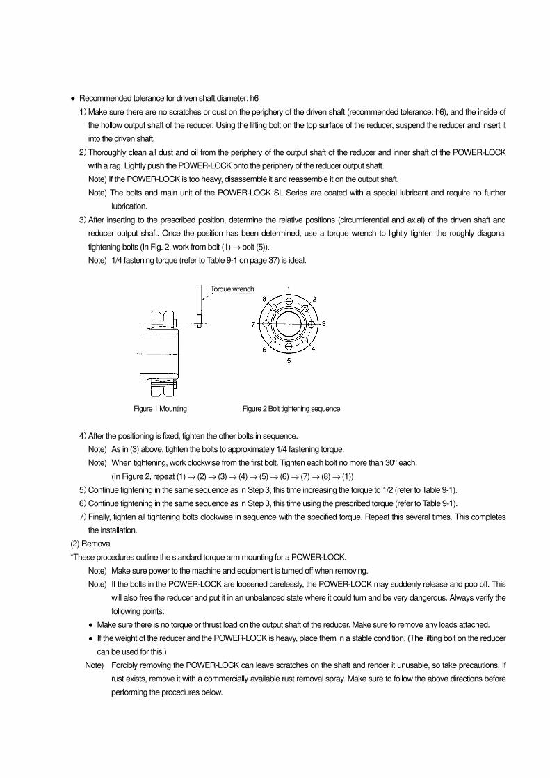
3) After inserting to the prescribed position, determine the relative positions (circumferential and axial) of the driven shaft and
reducer output shaft. Once the position has been determined, use a torque wrench to lightly tighten the roughly diagonal
tightening bolts (In Fig. 2, work from bolt (1) → bolt (5)).
Note) 1/4 fastening torque (refer to Table 9-1 on page 37) is ideal.
Figure 1 Mounting Figure 2 Bolt tightening sequence
4) After the positioning is fixed, tighten the other bolts in sequence.
Note) As in (3) above, tighten the bolts to approximately 1/4 fastening torque.
Note) When tightening, work clockwise from the first bolt. Tighten each bolt no more than 30° each.
(In Figure 2, repeat (1) → (2) → (3) → (4) → (5) → (6) → (7) → (8) → (1))
5) Continue tightening in the same sequence as in Step 3, this time increasing the torque to 1/2 (refer to Table 9-1).
6) Continue tightening in the same sequence as in Step 3, this time using the prescribed torque (refer to Table 9-1).
7) Finally, tighten all tightening bolts clockwise in sequence with the specified torque. Repeat this several times. This completes
the installation.
(2) Removal
*These procedures outline the standard torque arm mounting for a POWER-LOCK.
Note) Make sure power to the machine and equipment is turned off when removing.
Note) If the bolts in the POWER-LOCK are loosened carelessly, the POWER-LOCK may suddenly release and pop off. This
will also free the reducer and put it in an unbalanced state where it could turn and be very dangerous. Always verify the
following points:
● Make sure there is no torque or thrust load on the output shaft of the reducer. Make sure to remove any loads attached.
● If the weight of the reducer and the POWER-LOCK is heavy, place them in a stable condition. (The lifting bolt on the reducer
can be used for this.)
Note) Forcibly removing the POWER-LOCK can leave scratches on the shaft and render it unusable, so take precautions. If
rust exists, remove it with a commercially available rust removal spray. Make sure to follow the above directions before
performing the procedures below.
Torque wrench
1) Loosen the POWER-LOCK tightening bolts in sequence. As mentioned in the notes, do not completely remove the bolts at
once. Loosen each tightening bolt head by about 30°.
2) After confirming that the POWER-LOCK has fully released, suspend the reducer by its lifting bolt and remove it from the
driven shaft.
(3) General notes
1) Always use a torque wrench to tighten the tightening bolts. Failure to use a torque wrench with an adjustable dial is
inaccurate and can cause problems. Also note that using a pipe as a lever gives inaccurate tightening torque and should
never be done.
2) Do not use any bolts other than those supplied with this product. In case of damage or loss, contact your Tsubakimoto
Chain Co. dealer for replacement or new bolts.
(4) Reusability
● If reusing the removed POWER-LOCK, thoroughly remove any dirt from it with a rag. The bolts and main unit of the
POWER-LOCK/SL Series are coated with a special lubricant. If you notice the coating is peeling off, coat it with molybdenum
anti-friction grease (Molycoat, etc.) prior to reuse.
(5) Ambient conditions
● The POWER-LOCK SL Series can be used outdoors in an ambient temperature range of -30°C to +200°C. However, in this
case the POWER-LOCK is considered part of the reducer which limits it to the ambient conditions of the reducer motor. Use the
POWER-LOCK in accordance with "Installation" in section 3, in page 11.
Table 9-1. Tightening bolts and tightening torque according to the reducer size
Reducer size SWJ50 SWJ63 SWJ70 EW/SW80 EW/SW 100
EW/SW 125
EW/SW 150
EW/SW 175
EW/SW 200
Tightening torque
Nm 11.8 11.8 11.8 11.8 29.4 29.4 57.8 57.8 98.0
kgfm 1.2 1.2 1.2 1.2 3.0 3.0 5.9 5.9 10.0
Bolt size M6 x 20 M6 x 20 M6 x 25 M6 x 25 M8 x 30 M8 x 35 M10 x 40 M10 x 40 M12 x 45
No. of bolts 7 7 8 10 7 12 9 12 10
9-2. Handling the taper bush specifications
(1) Mounting procedures
These procedures outline the standard torque arm mounting.
● The taper bush is shipped temporarily fixed to the output shaft. After removing it from the reducer, mount it on the
machine/equipment using the procedures below.
● These procedures are for standard installation (mount the taper bush on the flange face side, position the flange toward the
machine/equipment side, and mount the taper bush between the machine/equipment and reducer).
● Recommended tolerance for driven shaft diameter: g7
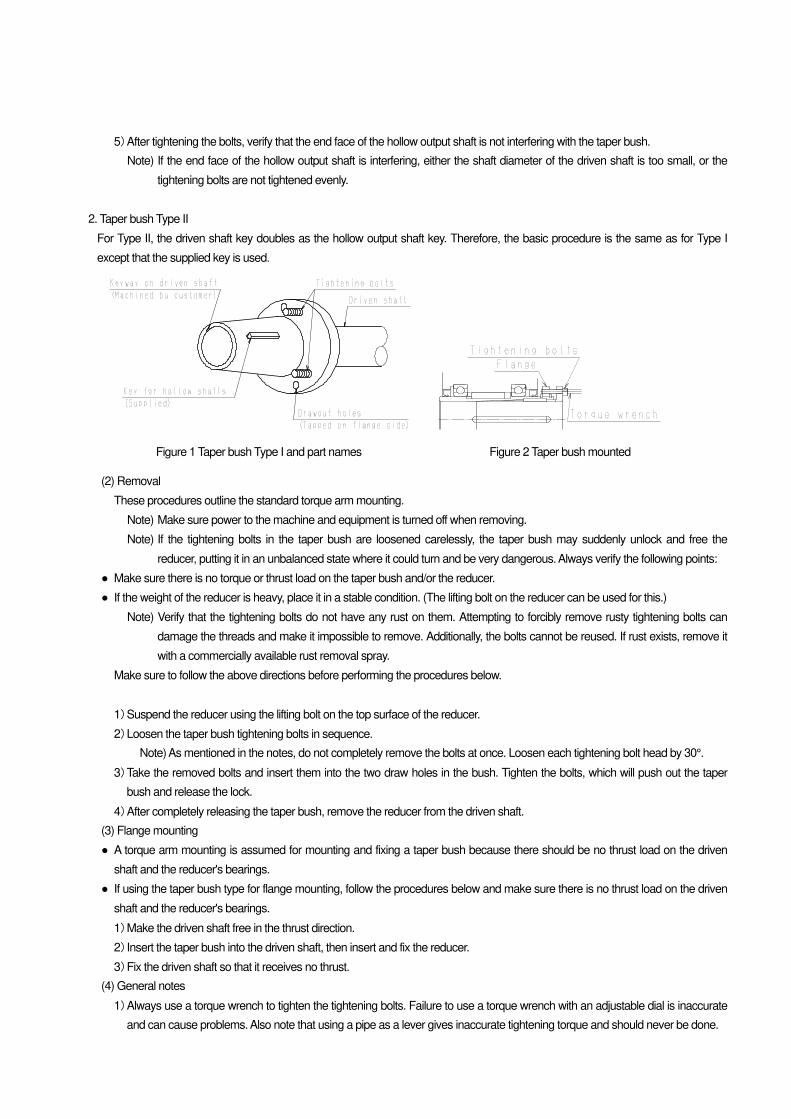
1. Taper bush Type I
1) Make sure there are no marks or dust on the outer periphery of the driven shaft and install the key prepared by the customer.
Note) Only the Type II driven shaft key is shipped with the reducer.
2) Thoroughly clean all dust and oil from the inner and outer peripheries of the taper bush with a rag. Then line up the driven shaft
key and insert the taper bush. Once inserted, install the provided key in the keyway on the outer periphery of the taper bush.
Note) Do not coat the taper bush with any oil.
3) Thoroughly clean all oil and dust from the inner periphery of the hollow output shaft on the reducer with a rag. Then suspend
the reducer by its lifting bolt and lineup the keyway as in Step 2 and insert it into the taper bush.
Note) SWJ50 to 63: No lifting bolts provided. Move by hand.
4) Verify that the reducer is installed in the correct position with respect to the machine/equipment. Align the tightening bolt to the
threads on the flange of the taper bush and tighten.
Note) Use a torque wrench set to the torque outlined in Table 9-2 on page 39 to accurately tighten the bolts.
5) After tightening the bolts, verify that the end face of the hollow output shaft is not interfering with the taper bush.
Note) If the end face of the hollow output shaft is interfering, either the shaft diameter of the driven shaft is too small, or the
tightening bolts are not tightened evenly.
2. Taper bush Type II
For Type II, the driven shaft key doubles as the hollow output shaft key. Therefore, the basic procedure is the same as for Type I
except that the supplied key is used.
Figure 1 Taper bush Type I and part names Figure 2 Taper bush mounted
(2) Removal
These procedures outline the standard torque arm mounting.
Note) Make sure power to the machine and equipment is turned off when removing.
Note) If the tightening bolts in the taper bush are loosened carelessly, the taper bush may suddenly unlock and free the
reducer, putting it in an unbalanced state where it could turn and be very dangerous. Always verify the following points:
● Make sure there is no torque or thrust load on the taper bush and/or the reducer.
● If the weight of the reducer is heavy, place it in a stable condition. (The lifting bolt on the reducer can be used for this.)
Note) Verify that the tightening bolts do not have any rust on them. Attempting to forcibly remove rusty tightening bolts can
damage the threads and make it impossible to remove. Additionally, the bolts cannot be reused. If rust exists, remove it
with a commercially available rust removal spray.
Make sure to follow the above directions before performing the procedures below.
1) Suspend the reducer using the lifting bolt on the top surface of the reducer.
2) Loosen the taper bush tightening bolts in sequence.
Note) As mentioned in the notes, do not completely remove the bolts at once. Loosen each tightening bolt head by 30°.
3) Take the removed bolts and insert them into the two draw holes in the bush. Tighten the bolts, which will push out the taper
bush and release the lock.
4) After completely releasing the taper bush, remove the reducer from the driven shaft.
(3) Flange mounting
● A torque arm mounting is assumed for mounting and fixing a taper bush because there should be no thrust load on the driven
shaft and the reducer's bearings.
● If using the taper bush type for flange mounting, follow the procedures below and make sure there is no thrust load on the driven
shaft and the reducer's bearings.
1) Make the driven shaft free in the thrust direction.
2) Insert the taper bush into the driven shaft, then insert and fix the reducer.
3) Fix the driven shaft so that it receives no thrust.
(4) General notes
1) Always use a torque wrench to tighten the tightening bolts. Failure to use a torque wrench with an adjustable dial is inaccurate
and can cause problems. Also note that using a pipe as a lever gives inaccurate tightening torque and should never be done.
2) Do not use any bolts other than those supplied with this product. In case of damage or loss, contact your Tsubakimoto Chain
Co. dealer for replacement or new bolts.
3) The taper bush tightening bolts are also used as draw bolts during removal. Provide enough room to remove the bolts by
referring to the detailed dimensions (bolt lengths and PCD) in the catalog.
(5) Reusability
● If reusing the removed taper bush, thoroughly remove any dirt from it with a rag.
(6) Ambient conditions
● The taper bush specifications are considered part of the reducer, which limits the specifications to the ambient conditions of the
reducer motor. Use the taper bush in accordance with "Installation" in section 3 in page 11.
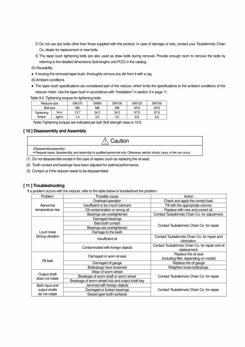
Table 9-2. Tightening torques for tightening bolts
Reducer size SWJ70 SW80 SW100 SW125 SW150
Bolt size M6 M8 M8 M10 M10
Tightening torque
Nm 13.7 34.3 34.3 67.6 67.6
kgfm 1.4 3.5 3.5 6.9 6.9
Note) Tightening torques are indicated per bolt. Bolt strength class is 10.9.
[ 10 ] Disassembly and Assembly
Caution
(Disassembly/assembly) � Request repair, disassembly, and assembly to qualified personnel only. Otherwise, electric shock, injury, or fire can occur.
(1) Do not disassemble except in the case of repairs (such as replacing the oil seal).
(2) Tooth contact and bearings have been adjusted for optimal performance.
(3) Contact us if the reducer needs to be disassembled.
[ 11 ] Troubleshooting
If a problem occurs with the reducer, refer to the table below to troubleshoot the problem.
Problem Possible cause Action
Abnormal temperature rise
Overload operation Check and apply the correct load.
Insufficient or too much lubricant Fill with the appropriate volume.
Oil contamination or wrong oil Replace with new and correct oil.
Bearings are overtightened Contact Tsubakimoto Chain Co. for adjustment.
Loud noise Strong vibration
Damaged bearings
Contact Tsubakimoto Chain Co. for repair. Bad tooth contact
Bearings are overtightened
Damage to the teeth
Insufficient oil Contact Tsubakimoto Chain Co. for repair and
lubrication.
Contaminated with foreign objects Contact Tsubakimoto Chain Co. for repair and oil
replacement.
Oil leak
Damaged or worn oil seal Replace the oil seal
(including filter, depending on model)
Damaged oil gauge Replace the oil gauge
Bolts/plugs have loosened Retighten loose bolts/plugs.
Output shaft does not rotate
Wear of worm wheel
Contact Tsubakimoto Chain Co. for repair. Breakage of worm shaft or worm wheel
Breakage of worm wheel hub and output shaft key
Both input and output shafts do not rotate
Jammed with foreign objects
Contact Tsubakimoto Chain Co. for repair. Damaged or broken bearings
Seized gear tooth surfaces
[ 12 ] Internal Construction and Parts List
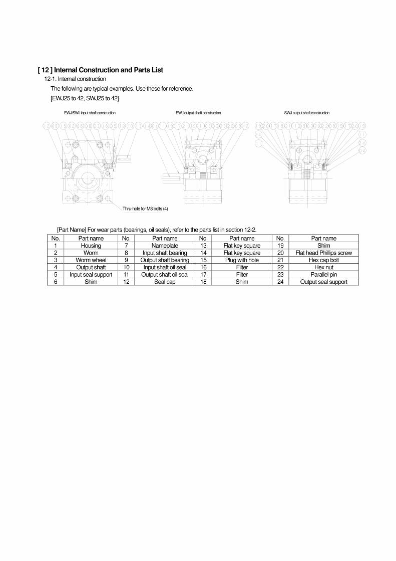
12-1. Internal construction
The following are typical examples. Use these for reference.
[EWJ25 to 42, SWJ25 to 42]
EWJ/SWJ input shaft construction EWJ output shaft construction SWJ output shaft construction
[Part Name] For wear parts (bearings, oil seals), refer to the parts list in section 12-2.
No. Part name No. Part name No. Part name No. Part name
1 Housing 7 Nameplate 13 Flat key square 19 Shim
2 Worm 8 Input shaft bearing 14 Flat key square 20 Flat head Phillips screw
3 Worm wheel 9 Output shaft bearing 15 Plug with hole 21 Hex cap bolt
4 Output shaft 10 Input shaft oil seal 16 Filter 22 Hex nut
5 Input seal support 11 Output shaft oil seal 17 Filter 23 Parallel pin
6 Shim 12 Seal cap 18 Shim 24 Output seal support
Thru-hole for M8 bolts (4)
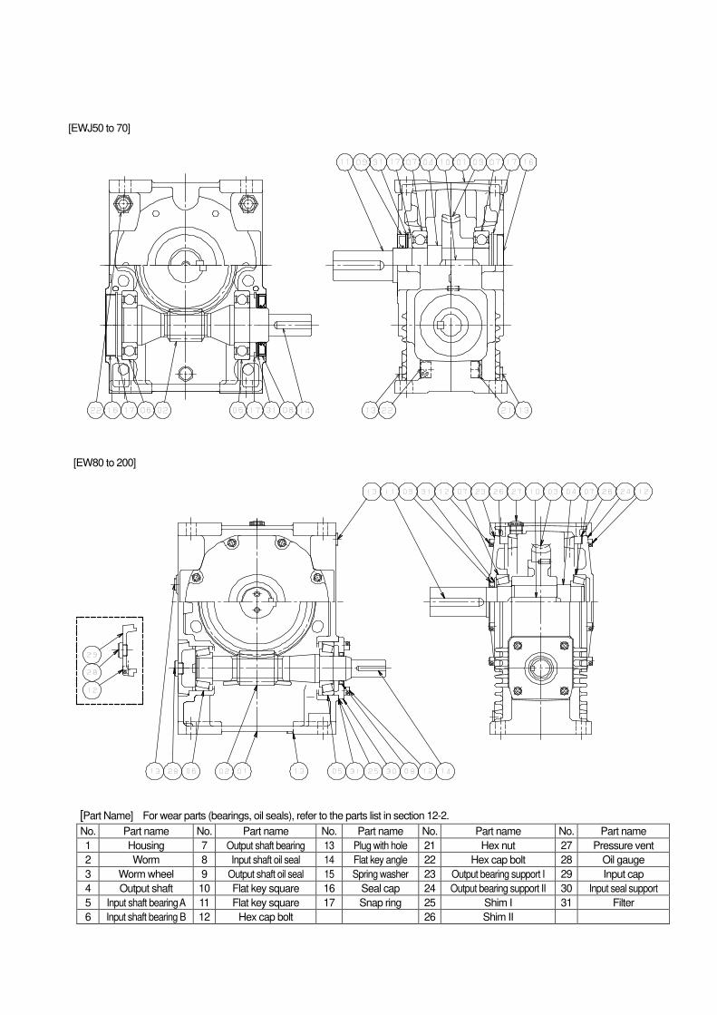
[EWJ50 to 70]
[EW80 to 200]
[Part Name] For wear parts (bearings, oil seals), refer to the parts list in section 12-2.
No. Part name No. Part name No. Part name No. Part name No. Part name
1 Housing 7 Output shaft bearing 13 Plug with hole 21 Hex nut 27 Pressure vent
2 Worm 8 Input shaft oil seal 14 Flat key angle 22 Hex cap bolt 28 Oil gauge
3 Worm wheel 9 Output shaft oil seal 15 Spring washer 23 Output bearing support I 29 Input cap
4 Output shaft 10 Flat key square 16 Seal cap 24 Output bearing support II 30 Input seal support
5 Input shaft bearing A 11 Flat key square 17 Snap ring 25 Shim I 31 Filter
6 Input shaft bearing B 12 Hex cap bolt 26 Shim II
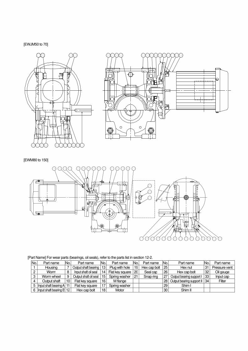
[EWJM50 to 70]
[EWM80 to 150]
[Part Name] For wear parts (bearings, oil seals), refer to the parts list in section 12-2.
No. Part name No. Part name No. Part name No. Part name No. Part name No. Part name
1 Housing 7 Output shaft bearing 13 Plug with hole 19 Hex cap bolt 25 Hex nut 31 Pressure vent
2 Worm 8 Input shaft oil seal 14 Flat key square 20 Seal cap 26 Hex cap bolt 32 Oil gauge
3 Worm wheel 9 Output shaft oil seal 15 Spring washer 21 Snap ring 27 Output bearing support I 33 Input cap
4 Output shaft 10 Flat key square 16 M flange 28 Output bearing support II 34 Filter
5 Input shaft bearing A 11 Flat key square 17 Spring washer 29 Shim I
6 Input shaft bearing B 12 Hex cap bolt 18 Motor 30 Shim II
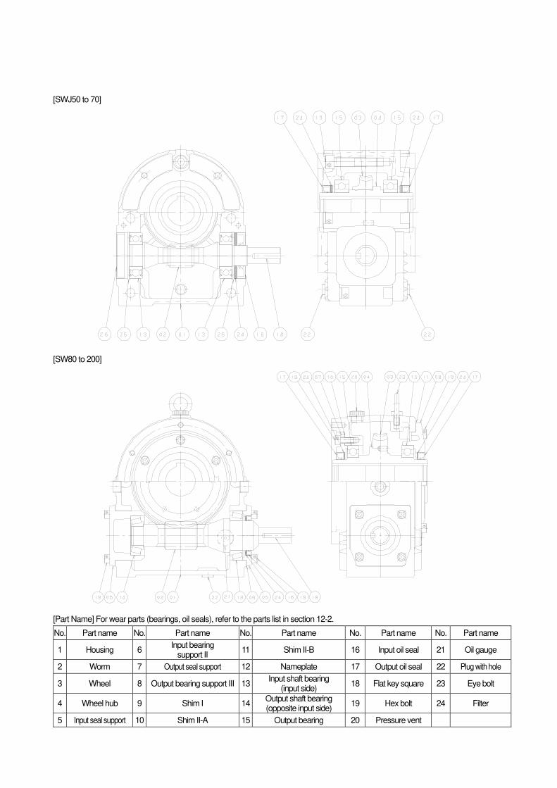
[SWJ50 to 70]
[SW80 to 200]
[Part Name] For wear parts (bearings, oil seals), refer to the parts list in section 12-2.
No. Part name No. Part name No. Part name No. Part name No. Part name
1 Housing 6 Input bearing
support II 11 Shim II-B 16 Input oil seal 21 Oil gauge
2 Worm 7 Output seal support 12 Nameplate 17 Output oil seal 22 Plug with hole
3 Wheel 8 Output bearing support III 13 Input shaft bearing
(input side) 18 Flat key square 23 Eye bolt
4 Wheel hub 9 Shim I 14 Output shaft bearing (opposite input side)
19 Hex bolt 24 Filter
5 Input seal support 10 Shim II-A 15 Output bearing 20 Pressure vent
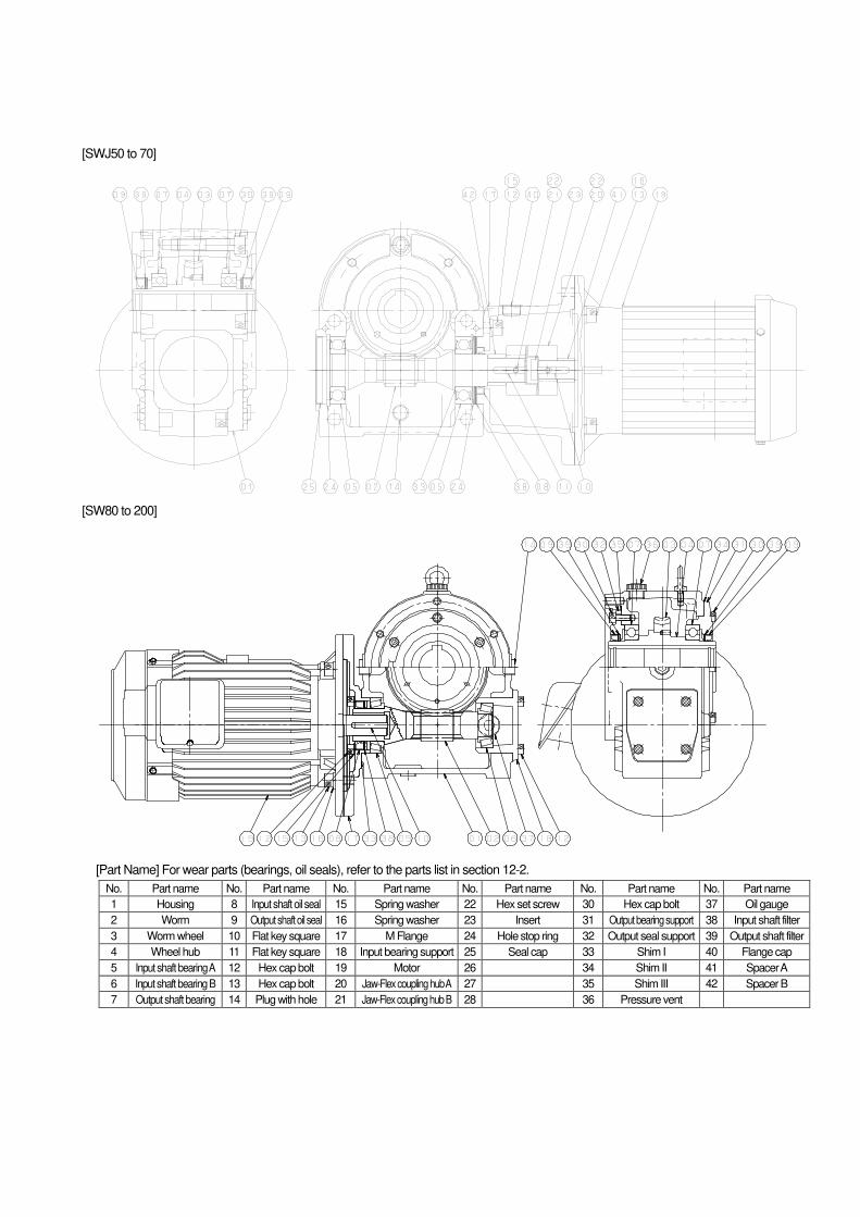
[SWJ50 to 70]
[SW80 to 200]
[Part Name] For wear parts (bearings, oil seals), refer to the parts list in section 12-2.
No. Part name No. Part name No. Part name No. Part name No. Part name No. Part name
1 Housing 8 Input shaft oil seal 15 Spring washer 22 Hex set screw 30 Hex cap bolt 37 Oil gauge
2 Worm 9 Output shaft oil seal 16 Spring washer 23 Insert 31 Output bearing support 38 Input shaft filter
3 Worm wheel 10 Flat key square 17 M Flange 24 Hole stop ring 32 Output seal support 39 Output shaft filter
4 Wheel hub 11 Flat key square 18 Input bearing support 25 Seal cap 33 Shim I 40 Flange cap
5 Input shaft bearing A 12 Hex cap bolt 19 Motor 26 34 Shim II 41 Spacer A
6 Input shaft bearing B 13 Hex cap bolt 20 Jaw-Flex coupling hub A 27 35 Shim III 42 Spacer B
7 Output shaft bearing 14 Plug with hole 21 Jaw-Flex coupling hub B 28 36 Pressure vent
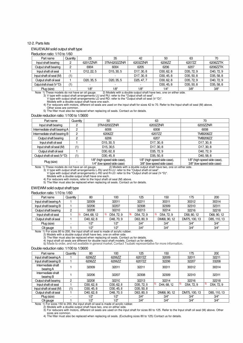
12-2. Parts lists
EWJ/EWJM solid output shaft type
Reduction ratio: 1/10 to 1/60 Part name Quantity 25 35 42 50 63 70
Input shaft bearing 2 6201ZZNR 3TM-6202ZZNR 6203ZZNR 6206ZZ 6207ZZ 6208ZZTK
Output shaft bearing 2 6904 6004 6205 6206 6207 6208ZZTK
Input shaft oil seal 1 D12, 22, 5 D15, 30, 5 D17, 30, 8 D30, 62, 8 D35, 72, 9 D40, 72, 9
Input shaft oil seal (M) (1) - - D17, 30, 8 D30, 45, 8 D35, 50, 8 D35, 58, 8
Output shaft oil seal 1 D20, 35, 5 D20, 35, 5 D25, 47, 7 D30, 62, 8 D35, 72, 9 D40, 72, 9
Output shaft oil seal (V-*D) (1) - - - D30, 45, 8 D35, 50, 8 D35, 58, 8
Plug (size) - 1/8" 1/8" 1/8" 1/4" 3/8" 3/8" Note 1) These models do not have an oil gauge. 2) Models with a double output shaft have two, one on either side.
3) V type with output shaft arrangements LU and RU: refer to the "Output shaft oil seal". V type with output shaft arrangements LD and RD: refer to the "Output shaft oil seal (V-*D)". Models with a double output shaft have one each.
4) For reducers with motors, different oil seals are used on the input shaft for sizes 42 to 70. Refer to the Input shaft oil seal (M) above. Other sizes are common.
5) The filter must also be replaced when replacing oil seals. Contact us for details.
Double reduction ratio: 1/100 to 1/3600
Part name Quantity 50 63 70
Input shaft bearing 2 3TM-6202ZZNR 6203ZZNR 6203ZZNR
Intermediate shaft bearing A 2 6006 6008 6008
Intermediate shaft bearing B 2 6206ZZ 6207ZZ TMB208ZZ
Output shaft bearing 2 6206 6207 TMB208ZZ
Input shaft oil seal 1 D15, 30, 5 D17, 30, 8 D17, 30, 8
Input shaft oil seal (M) (1) D15, 30,5 D17, 30, 8 D17, 30, 8
Output shaft oil seal 1 D30, 62, 8 D35, 72, 9 D40, 72, 9
Output shaft oil seal (V-*D) (1) D30, 45, 8 D35, 50, 8 D40, 58, 8
Plug (size) - 1/8" (high speed side case), 1/4" (low speed side case)
1/8" (high speed side case), 3/8" (low speed side case)
1/8" (high speed side case), 3/8" (low speed side case)
Note 1) These models do not have an oil gauge. 2) Models with a double output shaft have two, one on either side. 3) V type with output shaft arrangements L-RU and R-LU: refer to the "Output shaft oil seal".
V type with output shaft arrangements L-RD and R-LD: refer to the "Output shaft oil seal (V-*D)". Models with a double output shaft have one each.
4) For reducers with motors, refer to the Input shaft oil seal (M) above. 5) The filter must also be replaced when replacing oil seals. Contact us for details.
EW/EWM solid output shaft type
Reduction ratio: 1/10 to 1/60 Part name Quantity 80 100 125 150 175 200
Input shaft bearing A 1 32009 32011 32211 30311 30312 30314
Input shaft bearing B 1 32206 32207 32308 32309 32310 32311
Output shaft bearing 2 32208 32210 32213 32214 32216 32218
Input shaft oil seal 1 D44, 68, 12 D54, 72, 9 D54, 72, 9 D54, 72, 9 D58, 80, 12 D68, 90, 12
Output shaft oil seal 1 D40, 62, 8 D48, 70, 9 D63, 80, 9 DM68, 90, 12 DM75, 100, 13 D85, 110, 13
Plug (size) - 1/2" 1/2" 3/4" 3/4" 3/4" 3/4"
Oil gauge 1 1/2" 1/2" 3/4" 3/4" 3/4" 3/4" Note 1) For sizes 80 to 200, the input shaft oil seal is made of acrylic rubber.
2) Models with a double output shaft have two, one on either side. 3) The filter must also be replaced when replacing oil seals. Contact us for details. 4) Input shaft oil seals are different for double input shaft models. Contact us for details. 5) Made to order, and not available in general market. Contact Tsubaki representative for more information.
Double reduction ratio: 1/100 to 1/3600
Part name Quantity 80 100 125 150 175 200
Input shaft bearing A 1 6206ZZ 6206ZZ 6207ZZ 32009 32011 32211
Input shaft bearing B 1 6206ZZ 6206ZZ 6207ZZ 32206 32207 33208
Intermediate shaft bearing A
1 32009 32011 32211 30311 30312 30314
Intermediate shaft bearing B
1 32206 32207 32308 32309 32310 32311
Output shaft bearing 2 32208 32210 32213 32214 32216 32218
Input shaft oil seal 1 D30, 62, 8 D30, 62, 8 D35, 72, 9 D44, 68, 12 D54, 72, 9 D54, 72, 9
Input shaft oil seal (M) (1) D30, 45, 8 D30, 45, 8 D35, 50, 8 - - -
Output shaft oil seal 1 D40, 62, 8 D48, 70, 9 D63, 80, 9 DM68, 90, 12 DM75, 100, 13 D85, 110, 13
Plug (size) - 1/2" 1/2" 3/4" 3/4" 3/4" 3/4"
Oil gauge 1 1/2" 1/2" 3/4" 3/4" 3/4" 3/4" Note 1) For sizes 150 to 200, the input shaft oil seal is made of acrylic rubber.
2) Models with a double output shaft have two, one on either side. 3) For reducers with motors, different oil seals are used on the input shaft for sizes 80 to 125. Refer to the Input shaft oil seal (M) above. Other
sizes are common. 4) The filter must also be replaced when replacing oil seals. (Excluding sizes 80 to 125) Contact us for details.
5) 5) 5) 5)
5) 5) 5)
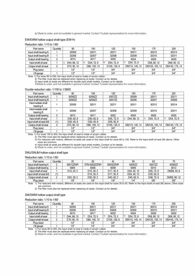
5) Made to order, and not available in general market. Contact Tsubaki representative for more information.
EW/EWM hollow output shaft type (EW-H)
Reduction ratio: 1/10 to 1/60
Part name Quantity 80 100 125 150 175 200
Input shaft bearing A 1 32009 32011 32211 30311 30312 30314
Input shaft bearing B 1 32206 32207 32308 32309 32310 32311
Output shaft bearing 2 6015 6017 6022 6024 6026 6030
Input shaft oil seal 1 D44, 68, 12 D54, 72, 9 D54, 72, 9 D54, 72, 9 D58, 80, 12 D68, 90, 12
Output shaft oil seal 2 D70, 90, 10 D80, 105, 13 D105, 135, 9 DM115, 145, 14 DM125, 155, 14 DM145, 175, 14
Plug (size) - 1/2" 1/2" 3/4" 3/4" 3/4" 3/4"
Oil gauge 1 1/2" 1/2" 3/4" 3/4" 3/4" 3/4" Note 1) For sizes 80 to 200, the input shaft oil seal is made of acrylic rubber.
2) The filter must also be replaced when replacing oil seals. Contact us for details. 3) Input shaft oil seals are different for double input shaft models. Contact us for details. 4)Made to order, and not available in general market. Contact Tsubaki representative for more information.
Double reduction ratio: 1/100 to 1/3600
Part name Quantity 80 100 125 150 175 200
Input shaft bearing A 1 6206ZZ 6206ZZ 6207ZZ 32009 32011 32211
Input shaft bearing B 1 6206ZZ 6206ZZ 6207ZZ 32206 32207 33208
Intermediate shaft bearing A
1 32009 32011 32211 30311 30312 30314
Intermediate shaft bearing B
1 32206 32207 32308 32309 32310 32311
Output shaft bearing 2 6015 6017 6022 6024 6026 6030
Input shaft oil seal 1 D30, 62, 8 D30, 62, 8 D35, 72, 9 D44, 68, 12 D54, 72, 9 D54, 72, 9
Input shaft oil seal (M) (1) D30, 45, 8 D30, 45, 8 D35, 50, 8 - - -
Output shaft oil seal 2 D70, 90, 10 D80, 105, 13 D105, 135, 9 DM115, 145, 14 DM125, 155, 14 DM145, 175, 14
Plug (size) - 1/2" 1/2" 3/4" 3/4" 3/4" 3/4"
Oil gauge 1 1/2" 1/2" 3/4" 3/4" 3/4" 3/4" Note 1) For sizes 150 to 200, the input shaft oil seal is made of acrylic rubber.
2) The filter must also be replaced when replacing oil seals. Contact us for details. 3) For reducers with motors, different oil seals are used on the input shaft for sizes 80 to 125. Refer to the Input shaft oil seal (M) above. Other
sizes are common. 4) Input shaft oil seals are different for double input shaft models. Contact us for details. 5) Made to order, and not available in general market. Contact Tsubaki representative for more information.
SWJ/SWJM hollow output shaft type
Reduction ratio: 1/10 to 1/60
Part name Quantity 25 35 42 50 63 70
Input shaft bearing A 2 6201ZZNR 3TM-6202ZZNR 6203ZZNR 6205ZZ 6207ZZ 6306ZZ
Output shaft bearing 2 6904 6006 6008 6009 6010 6012
Input shaft oil seal 1 D12, 22, 5 D15, 30. 5 D17, 30, 8 D24, 52, 10 D35, 72, 9 DM28, 40, 8
Input shaft oil seal (M) (1) - D15, 30, 5 D17, 30, 8 D24, 45, 10 D35, 50, 8 -
Output shaft oil seal 2 D20, 35, 5 D30, 50, 5 D40, 62, 5 D45, 62, 9 D48, 70, 9 DM58, 80, 12
Plug (size) - 1/8" 1/8" 1/8" 1/4" 3/8" 3/8" Note 1) For reducers with motors, different oil seals are used on the input shaft for sizes 35 to 63. Refer to the Input shaft oil seal (M) above. Other sizes
are common. 2) The filter must also be replaced when replacing oil seals. Contact us for details.
SW/SWM hollow output shaft type
Reduction ratio: 1/10 to 1/60
Part name Quantity 80 100 125 150 175 200
Input shaft bearing A 1 32009 32011 32211 30311 30312 30314
Input shaft bearing B 1 32206 32207 33208 32309 32310 32311
Output shaft bearing 2 6015 6017 6022 6024 6026 6030
Input shaft oil seal 1 D44, 68, 12 D54, 72, 9 D54, 72, 9 D54, 72, 9 D58, 80, 12 D68, 90, 12
Output shaft oil seal 2 D70, 90, 10 D80, 105, 13 D105, 135, 9 DM115, 145, 14 DM125, 155, 14 DM145, 175, 14
Plug (size) - 1/2" 1/2" 3/4" 3/4" 3/4" 3/4"
Oil gauge 1 1/2" 1/2" 3/4" 3/4" 3/4" 3/4" Note 1) For sizes 80 to 200, the input shaft oil seal is made of acrylic rubber.
2) The filter must also be replaced when replacing oil seals. Contact us for details. 3) Made to order, and not available in general market. Contact Tsubaki representative for more information.
4) 4) 4) 4)
5) 5) 5)
3) 3) 3) 3)
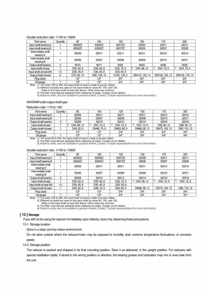
Double reduction ratio: 1/100 to 1/3600
Part name Quantity 80 100 125 150 175 200
Input shaft bearing A 1 6206ZZ 6206ZZ 6207ZZ 32009 32011 32211
Input shaft bearing B 1 6206ZZ 6206ZZ 6207ZZ 32206 32207 32208
Intermediate shaft bearing A
1 32009 32011 32211 30311 30312 30314
Intermediate shaft bearing B
1 32206 32207 33208 32309 32310 32311
Output shaft bearing 2 6015 6017 6022 6024 6026 6030
Input shaft oil seal 1 D30, 62, 8 D30, 62, 8 D35, 72, 9 D44, 68, 12 D54, 72, 9 D54, 72, 9
Input shaft oil seal (M) (1) D30, 45, 8 D30, 45, 8 D35, 50, 8 - - -
Output shaft oil seal 2 D70, 90, 10 D80, 105, 13 D105, 135, 9 DM115, 145, 14 DM125, 155, 14 DM145, 175, 14
Plug (size) - 1/2" 1/2" 3/4" 3/4" 3/4" 3/4"
Oil gauge 1 1/2" 1/2" 3/4" 3/4" 3/4" 3/4" Note 1) For sizes 150 to 200, the input shaft oil seal is made of acrylic rubber.
2) Different oil seals are used on the input shaft for sizes 80, 100, and 125. Refer to the Input shaft oil seal (M) above. Other sizes are common.
3) The filter must also be replaced when replacing oil seals. Contact us for details. 4) Made to order, and not available in general market. Contact Tsubaki representative for more information.
SW/SWM solid output shaft type
Reduction ratio: 1/10 to 1/60
Part name Quantity 80 100 125 150 175 200
Input shaft bearing A 1 32009 32011 32211 30311 30312 30314
Input shaft bearing B 1 32206 32207 33208 32309 32310 32311
Output shaft bearing 2 32208 32210 32213 32214 32216 32218
Input shaft oil seal 1 D44, 68, 12 D54, 72, 9 D54, 72, 9 D54, 72, 9 D58, 80, 12 D68, 90, 12
Output shaft oil seal 1 D40, 62, 8 DM48, 70, 9 DM63, 80, 9 DM68, 90, 12 DM75, 100, 13 D85, 110, 13
Plug (size) - 1/2" 1/2" 3/4" 3/4" 3/4" 3/4"
Oil gauge 1 1/2" 1/2" 3/4" 3/4" 3/4" 3/4" Note 1) For sizes 80 to 200, the input shaft oil seal is made of acrylic rubber.
2) The filter must also be replaced when replacing oil seals. Contact us for details. 3) Made to order, and not available in general market. Contact Tsubaki representative for more information.
Double reduction ratio: 1/100 to 1/3600
Part name Quantity 80 100 125 150 175 200
Input shaft bearing A 1 6206ZZ 6206ZZ 6207ZZ 32009 32011 32211
Input shaft bearing B 1 6206ZZ 6206ZZ 6207ZZ 32206 32207 33208
Intermediate shaft bearing A
1 32009 32011 32211 30311 30312 30314
Intermediate shaft bearing B
1 32206 32207 33208 32309 32310 32311
Output shaft bearing 2 32208 32210 32213 32214 32216 32218
Input shaft oil seal 1 D30, 62, 8 D30, 62, 8 D35, 72, 9 D44, 68, 12 D54, 72, 9 D54, 72, 9
Input shaft oil seal (M) (1) D30, 45, 8 D30, 45, 8 D35, 50, 8 - - -
Output shaft oil seal 1 D40, 62, 8 D48, 70, 9 D63, 80, 9 DM68, 90, 12 DM75, 100, 13 D85, 110, 13
Plug (size) - 1/2" 1/2" 3/4" 3/4" 3/4" 3/4"
Oil gauge 1 1/2" 1/2" 3/4" 3/4" 3/4" 3/4" Note 1) For sizes 150 to 200, the input shaft oil seal is made of acrylic rubber.
2) Different oil seals are used on the input shaft for sizes 80, 100, and 125. Refer to the Input shaft oil seal (M) above. Other sizes are common.
3) The filter must also be replaced when replacing oil seals. Contact us for details. 4) Made to order, and not available in general market. Contact Tsubaki representative for more information.
[ 13 ] Storage
If you will not be using the reducer immediately upon delivery, store it by observing these precautions.
13-1. Storage location
Store in a clean and dry indoor environment.
Do not store outside where the reducer/motor may be exposed to humidity, dust, extreme temperature fluctuations, or corrosive
gases.
13-2. Storage position
The reducer is packed and shipped in its final mounting position. Store it as delivered, in the upright position. For reducers with
special installation styles, if stored in the wrong position or direction, the bearing grease and lubrication may mix or even leak from
the unit.
3) 3) 3)
3) 3) 3) 3)
4) 4) 4)
13-3. Storage period
(1) The maximum storage period is six months.
(2) Special anti-rust treatment may be required for storage over six months. Contact us for details.
13-4. Operating the reducer after storage
(1) Non-metallic parts like oil seals, oil gauges, and oil plugs wear easily from environmental conditions such as extreme
temperatures and ultraviolet rays. Make sure to inspect these parts and replace them if damaged, before operation.
(2) Make sure there is no abnormal noise, vibration, or overheating. If you discover any abnormalities, stop operation
immediately and contact your distributor or Tsubakimoto Chain Co.
[ 14 ] Others
14-1. Disposal
Dispose of the reducer and lubrication oil in accordance with regulations on disposal of general industrial waste.
14-2. Painting
Painting of the product by the customer can cause oil leaks, so be sure to mask the oil seal parts to prevent paint from adhering to
them.
14-3. Motor specifications
See the instruction manual of the motor for the motor specifications.
14-4. Special specifications
For special specifications, refer to this instruction manual and the external drawings (specification and delivery drawings). Contact
your distributor or Tsubakimoto Chain Co. if you have any questions regarding this instruction manual.
[ 15 ] Warranty
15-1. Warranty period without charge
This period of warranty shall be 18 months from the time of shipment or 12 months from the time the product was first used (including completed assembly of this product to the equipment of the customer), whichever is shorter. However, the warranty period may vary, depending on the usage conditions.
15-2. Warranty coverage
During the limited warranty period, a failure in a Tsubaki product installed, used, and maintained according to the catalog, instruction manual, or other appropriate documents can be returned to Tsubaki for replacement or repair free of charge. However, please note that the limited warranty covers only Tsubaki products. The following expenses will not be covered by the warranty. (Instruction manuals and other appropriate documents include any documents specially submitted to the customer.)
(1) Any costs related to the removal or re-installation of Goods from the Buyer’s equipment or machine to repair or replace parts.
(2) Cost to transport Buyer’s equipment or machines to replace or repair.
(3) Costs to reimburse any profit loss due to any repair or damage and
15-3. Warranty with charge
Seller will charge for any investigation and repair of Goods (even during the warranty period without charge) caused by:
(1) Improper installation by failing to follow the instruction manual.
(2) Insufficient maintenance or improper operation by the Buyer.
(3) Incorrect installation of Goods onto other equipment or machines.
(4) Structure change of the Goods by any modifications or alterations by the Buyer.
(5) Any repair by engineers other than the Seller or those designated by the Seller.
(6) Operation in an inappropriate environment not specified in the manual.
(7) Force Majeure or forces beyond the Seller’s control such as a natural disaster and injustices committed by a third party.
(8) Secondary damage or problems incurred by the Buyer’s equipment or machines.
(9) Defective parts supplied or specified by the Buyer.
(10) Product failures due to wiring failures caused by the Buyer.
(11) The product reaching the end of its normal service life according to the operating conditions.
(12) Loss or damage not liable to the Seller.
15-4. Dispatching of Tsubaki engineers
Service expenses such as those incurred when dispatching engineers to perform an investigation, adjustment, or trial operation of a Tsubaki product will be charged separately.

[MENO]
TSUBAKIMOTO CHAIN CO.
Global Associated Partners:
Tsubakimoto Singapore Pte. Ltd.
https://tsubaki.sg/
U.S. Tsubaki Power Transmission, LLC
https://www.ustsubaki.com/
Taiwan Tsubakimoto Co.
https://tsubakimoto.com.tw/
Tsubaki of Canada Limited
https://tsubaki.ca/
Tsubakimoto Chain (Shanghai) Co., Ltd.
https://tsubaki.cn/
Tsubaki Australia Pty. Limited
https://tsubaki.com.au/
Tsubakimoto Europe B.V.
https://tsubaki.eu/
Tsubakimoto U.K. Ltd.
https://tsubaki.eu/
Tsubakimoto Korea Co., Ltd.
https://tsubakimoto-tck.co.kr/
1-1, Kohtari-Kuresumi, Nagaokakyo
Kyoto 617- 0833
Japan
Website: https://tsubakimoto.com/