Embed Size (px)
Citation preview
CSE386- Advanced Programming Lab Manual
KALASALINGAM UNIVERSITY(Kalasalingam Academy of Research and Education)
DEPARTMENT OF COMPUTER SCIENCE AND ENGINEERING
LAB MANUAL
ADVANCED PROGRAMMING LAB(CSE386)
III YEAR B.TECH
ACADEMIC YEAR 2011-2012
1
CSE386- Advanced Programming Lab Manual
Aim
To introduce the necessary background, the basic algorithms, and the applications
of computer graphics and image processing. To make the students to be familiar with
various image editing and animation software for developing multimedia applications.
Prerequisites:
General understanding of programming concepts and algorithms
Good programming experience in C.
Familiarity with an image editing software and animation software.
Good creativity and imagination skill.
Objectives:
To implement various line, circle and ellipse drawing algorithms.
To implement 2D and 3D transformations.
To implement various clipping algorithms.
To perform conversion of color models.
To implement the simple animations.
To implement the projections of 3D objects.
Software and Hardware Requirements:
Software:
Operating System – Windows XP, 2000, MS-DOS
Turbo C with graphics packages, Flash
Hardware:
Intel Pentium4 processor
Color Monitor, keyboard, mouse
2
CSE386- Advanced Programming Lab Manual
Do’s and Don’ts:
Do’s:
Be punctual.
Follow the dress code.
Remove the foot wears outside the lab and arrange them neatly.
Keep your personal belongings in the allotted place.
Submit the observation for current experiment and record of previous
experiments.
Use the allotted system and login as per the given instruction.
Take the printouts regularly.
While leaving the lab, arrange the chairs in a proper way.
Maintain discipline and silence inside the lab.
Don’ts:
Don’t use the system for typing letters, reports etc., during lab hours.
Don’t use others login.
Don’t change the configuration and system’s settings.
Don’t bring floppies, CD’s inside the lab without permission.
Don’t load unauthorized software.
Method of Assessment:
Aim = 5
Algorithm = 20
Coding = 30
Execution of program = 30
Results = 5
Viva Voce = 10
Total = 100
3
CSE386- Advanced Programming Lab Manual
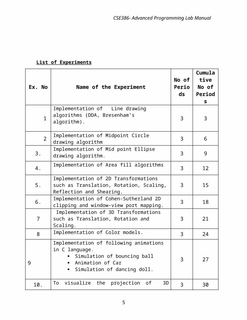
List of Experiments
Ex. No Name of the Experiment No of Periods
Cumulative No of Periods
1Implementation of Line drawing algorithms (DDA, Bresenham’s algorithm). 3 3
2 Implementation of Midpoint Circle drawing algorithm 3 6
3.Implementation of Mid point Ellipse drawing algorithm.
3 9
4.Implementation of Area fill algorithms
3 12
5.Implementation of 2D Transformations such as Translation, Rotation, Scaling, Reflection and Shearing. 3 15
6.Implementation of Cohen-Sutherland 2D clipping and window-view port mapping. 3 18
7 Implementation of 3D Transformations such as Translation, Rotation and Scaling. 3 21
8 Implementation of Color models. 3 24
9
Implementation of following animations in C language. Simulation of bouncing ball Animation of Car Simulation of dancing doll.
3 27
10. To visualize the projection of 3D images 3 30
4
CSE386- Advanced Programming Lab Manual
************************************************************************
EX. NO. 1 a DDA LINE DRAWING ALGORITHM
************************************************************************
Aim:
To draw a straight line using DDA Line Drawing Algorithm.
Logical Description:
DDA = Digital Differential AnalyzerIdea: Determine the pixel’s y coordinate by evaluating the change in y position of the ideal line when x increases by 1
y = x + b=x2-x1=y2-y1
• Suppose the k-th pixel along the line has been drawn and is (xk, yk)• What is the y value of the next pixel to be drawn?• yk+1 = yk+m =mAn incremental algorithm - next step uses only values from theprevious step to reduce computation
Derivation of DDA incremental algorithm
Consider a step then the subsequent step:kth step: yk = m xk + b (true given any xk)k+1th step: xk+1 = xk + 1yk+1 = m xk+1 + b= m (xk + 1) + b= m xk + m + b= ( yk ) + my = x + bx2-x1y2-y1=myk+1 = yk+m
5
CSE386- Advanced Programming Lab Manual
Algorithm:
Step 1: Input the two line end points and store the left end point in (xa,ya) and right end point in (xb,yb).
Step 2: Calculate the x intervals and y intervals ∆x = xa – xb and ∆y = ya – yb.
Step 3: Check the condition if ∆x > ∆y then assign Steps = ∆x
elseSteps = ∆y
Step 4: Increment the values of x and y as followsxinc = ∆x / Stepsyinc = ∆y / Steps
Step 5: Assign the value of xa to x and ya to y .Step 6: Using the command setpixel assign the pixel intensity a follows
setpixel (x,y,1)Step 7: Assign a loop for k = 0 to stepsStep 8: Assign the value x = x + xinc and y = y + yincStep 9: Using the command setpixel assign the pixel intensity a follows
setpixel (x,y,1)Step 10: Repeat the steps 8 and 9 until steps.
Sample Input:
Enter the line end points:
100
100
300
400
Sample output:
6
CSE386- Advanced Programming Lab Manual
************************************************************************EX. NO. 1 b BRESENHAM’S LINE DRAWING ALGORITHM
************************************************************************
Aim:
To draw a straight line using Bresenham’s line drawing algorithm.
Logical Description: The endpoints of the line are the pixels at (x0, y0) and (x1, y1), where the first
coordinate of the pair is the column and the second is the row. The algorithm will be initially presented only for the octant in which the segment
goes down and to the right (x0≤x1 and y0≤y1 ) Its horizontal projection x1 − x0 is longer than the vertical projection y1 − y0 (in
other words, the line has a slope less than 1 and greater than 0.) In this octant, for each column x between x0 and x1, there is exactly one row y
(computed by the algorithm) containing a pixel of the line, while each row between y0 and y1 may contain multiple rasterized pixels.
Bresenham's algorithm chooses the integer y corresponding to the pixel center that is closest to the ideal (fractional) y for the same x; on successive columns y can remain the same or increase by 1. The general equation of the line through the endpoints is given by:
Since we know the column, x, the pixel's row, y, is given by rounding this quantity to the nearest integer:
The slope (y1 − y0) / (x1 − x0) depends on the endpoint coordinates only and can be precomputed, and the ideal y for successive integer values of x can be computed starting from y0 and repeatedly adding the slope.
Algorithm:
Step 1: Input the two line end points and store the left end point in (x0,y0)Step 2: Load (x0,y0) into the frame buffers and plot the first point.Step 3: Calculate the constants ∆x, ∆y, 2∆y, and 2∆y - 2∆x and obtain the starting Decision parameter as
P0 = 2∆y - ∆xStep 4: At each xk along the line, starting at k=0 perform the following test.
If pk<0, the next point to plot is (xk + 1, yk) andPk + 1 = Pk+ 2∆y
Otherwise the next point to plot is (xk + 1, yk + 1) andPk+ 1 = pk + 2∆y - 2∆x
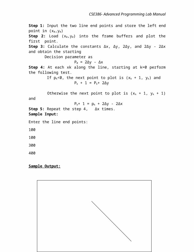
Step 5: Repeat the step 4, ∆x times.Sample Input:
7
CSE386- Advanced Programming Lab Manual
Enter the line end points:
100
100
300
400
Sample Output:
8
CSE386- Advanced Programming Lab Manual
************************************************************************EX. NO. 2 MID POINT CIRCLE DRAWING USING BRESENHAM’S ALGORITHM
************************************************************************
Aim:
To draw a circle using mid-point circle drawing algorithm.
Logical Description: The algorithm starts accordingly with the circle equation x2 + y2 = r2. We consider
first only the first octant and draw a curve which starts at point (r,0) and proceeds to the top right, reaching the angle of 45°.
The "fast" direction here is the y direction. The algorithm always does a step in the positive y direction (upwards), and every now and then also has to do a step in the "slow" direction, the negative x direction.
The frequent computations of squares in the circle equation, trigonometric expressions or square roots can again be avoided by dissolving everything into single steps and recursive computation of the quadratic terms from the preceding ones.
From the circle equation we obtain the transformed equation 0=x²+y²-r², with r² to be computed only a single time during initialization, x2 = (xpreceding − 1)2 = xpreceding2 − 2 × xpreceding + 1 (according for y), where x2 (or xpreceding2) is kept as an own variable. Additionally we need to add the mid point coordinates when setting a pixel. These frequent integer additions do not limit the performance much, as we can spare those square (root) computations in the inner loop in turn. Again the zero in the transformed circle equation is replaced by the error term.
The initialization of the error term is derived from an offset of ½ pixel at the start. Until the intersection with the perpendicular line, this leads to an accumulated value of r in the error term, so that this value is used for initialization.
Algorithm:
Step 1: Input radius r and circle center (xc,yc) and obtain the first point on the circumference of a circle centered on the origin as
(x0,y0) = (0,r)Step 2: Calculate the initial value of the decision parameter as
P0 = 5/4 – rStep 3: At each xk position , starting at k=0, perform the following test:
If pk<0, the next point to plot along the circle centered on (0,0) is (xk + 1, yk) and Pk + 1 = Pk+ 2 xk+1 + 1
Otherwise the next point to plot is (xk + 1, yk - 1) and
9
CSE386- Advanced Programming Lab Manual
Pk+ 1 = pk + 2 xk+1 + 1 - 2 yk+1
Where 2 xk+1 = 2 xk + 2 and 2 yk+1 = 2 yk - 2Step 4: Determine symmetry points in other seven octants.Step 5: Move each calculated pixel position (x,y) onto the circular path centered
on (xc,yc) and plot the coordinate values:x = x + xc
y = y + yc
Step 6: Repeat steps 3 through 5 until x ≥ y.
Sample Input
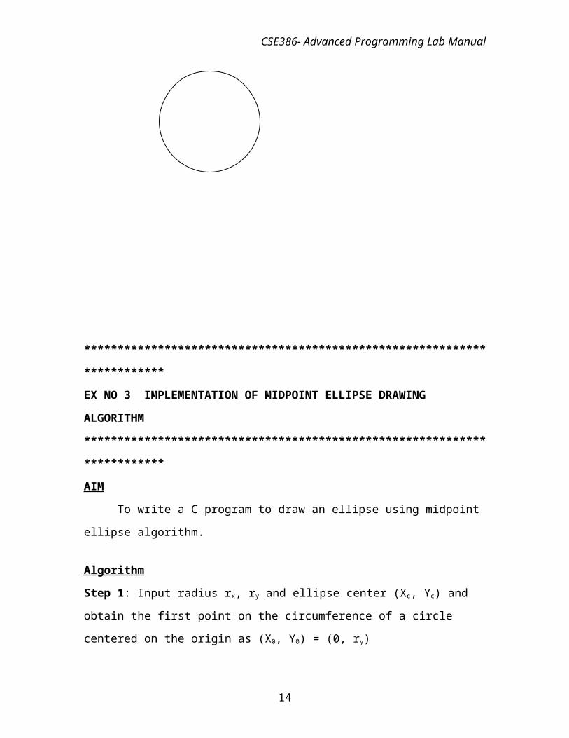
Enter the center point of the circle:100200Enter the radius of the circle:30
Output:
************************************************************************
10
CSE386- Advanced Programming Lab Manual
EX NO 3 IMPLEMENTATION OF MIDPOINT ELLIPSE DRAWING
ALGORITHM
************************************************************************
AIM
To write a C program to draw an ellipse using midpoint ellipse algorithm.
Algorithm
Step 1: Input radius rx, ry and ellipse center (Xc, Yc) and obtain the first point on the
circumference of a circle centered on the origin as (X0, Y0) = (0, ry)
Step 2: Calculate the initial values of the decision parameter in region 1 as
P10 = r2y – r2
x ry + 1/4 r2x
Step 3: At each Xk position in region 1, starting at k = 0, perform the following test:
If P1k < 0, the next point to plot is (Xk+1, Yk) and
P1k+1 = P1k+2 r2yXk+1 + r2
y
Otherwise the next point is (Xk+1, Yk-1) and
P1k+1 = P1k+2 r2yXk+1 - 2r2
xYk+1 + r2y
With
2 r2yXk+1=2 r2
yXk+ 2r2y
2r2xYk+1=2r2
xYk- 2r2x
Step 4: Calculate the initial values of the decision parameter in region 2 as
P20 = r2y(X0+1/2)2+ r2
x(Y0 – 1)2- r2x r2
y
Step 5: At each position starting at Yk position in region 2, starting at k = 0,
perform the following test:
If P2k > 0, the next point to plot is (Xk, Yk-1) and
P2k+1 = P2k - 2 r2yYk+1 + r2
x
Otherwise the next point is (Xk+1, Yk-1) and
P2k+1 = P2k - 2 r2yXk+1 - 2r2
xYk+1 + r2x
Step 6: Determine symmetry points in the other three octants
Step 7: Move each pixel position(X, Y) onto the circular path centered on
(Xc, Yc) and plot the coordinate values as
X = X + Xc Y = Y + Yc
11
CSE386- Advanced Programming Lab Manual
Step 8: Repeat steps for region 1 until 2 r2yX>=2 r2
xY.
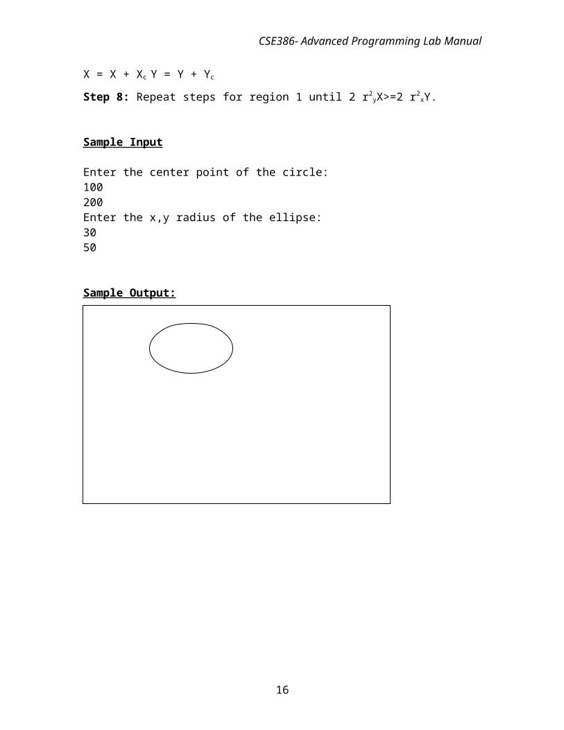
Sample Input
Enter the center point of the circle:100200Enter the x,y radius of the ellipse:3050
Sample Output:
12
CSE386- Advanced Programming Lab Manual
***********************************************************************
EX NO 4 IMPLEMENTATION OF AREA FILL ALGORITHMS
**********************************************************************
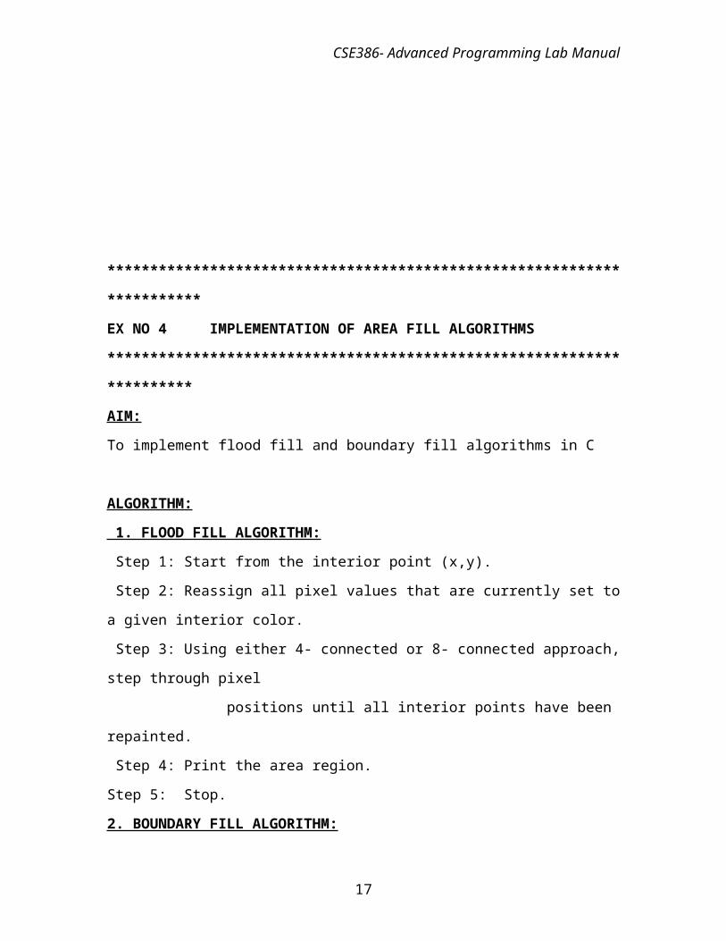
AIM:
To implement flood fill and boundary fill algorithms in C
ALGORITHM:
1. FLOOD FILL ALGORITHM:
Step 1: Start from the interior point (x,y).
Step 2: Reassign all pixel values that are currently set to a given interior color.
Step 3: Using either 4- connected or 8- connected approach, step through pixel
positions until all interior points have been repainted.
Step 4: Print the area region.
Step 5: Stop.
2. BOUNDARY FILL ALGORITHM:
Step 1: Start from the interior point (x,y).
Step 2: The Neighboring positions to determine whether they are of the boundary color.
Step 3: It not, they are painted with the fill color, and their neighbors are tested.
Step 4 : This process continues until all pixels up to the boundary color for the area have
been tested.
Step 5: Stop
Sample Input and output :
************************************************************************
13
CSE386- Advanced Programming Lab Manual
EX. NO. 5 2D TRANSFORMATIONS
************************************************************************
Aim:
To implement the 2D transformations such as Scaling, Rotation and Translation.
Logical Description
Given a 2D object, transformation is to change the object’s Position (translation)Size (scaling)Orientation (rotation)Shapes (shear)
TranslationRe-position a point along a straight line Given a point (x,y), and the translation distance (tx,ty)
The new point: (x’, y’) x’ = x + tx y’ = y + ty OR P’ = P + T where P’ = x’ p = x T = tx y’ y ty
Scaling Alter the size of an object by a scaling factor (Sx, Sy), i.e.
x’ = x . Sx = x’ Sx 0 xy’ = y . Sy = y’ = 0 Sy y
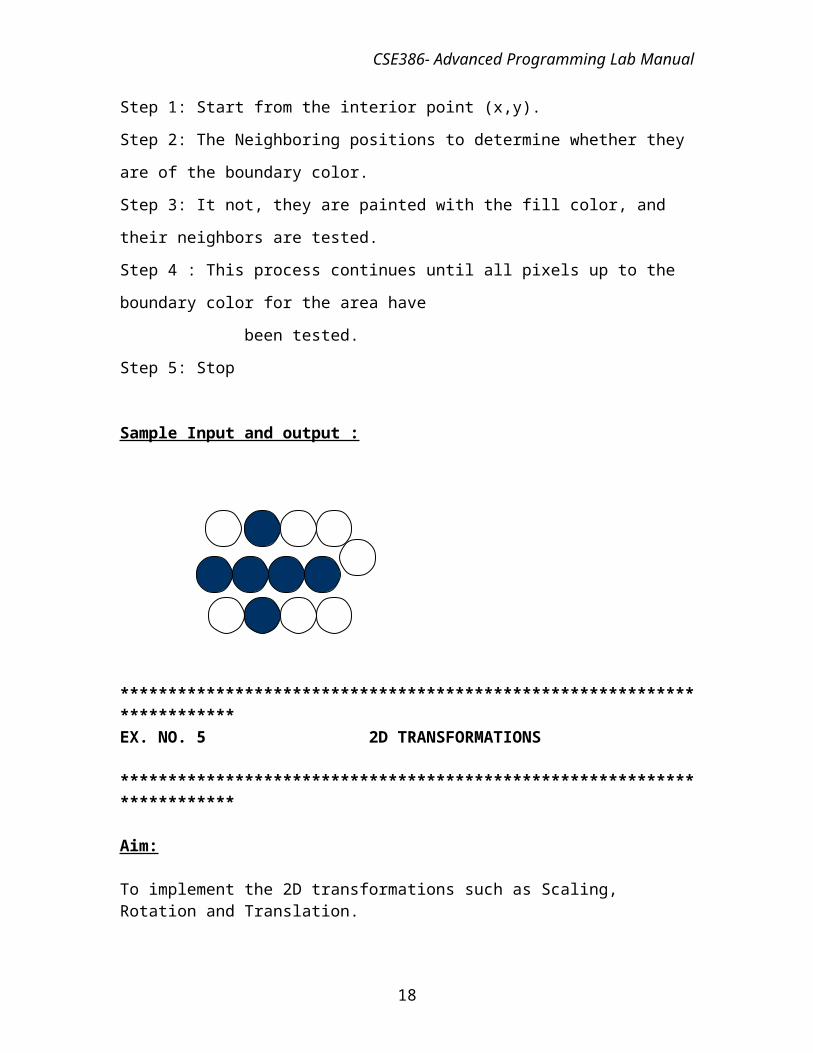
Rotation
Default rotation center: Origin (0,0)
> 0 : Rotate counter clockwise
< 0 : Rotate clockwise
14
CSE386- Advanced Programming Lab Manual
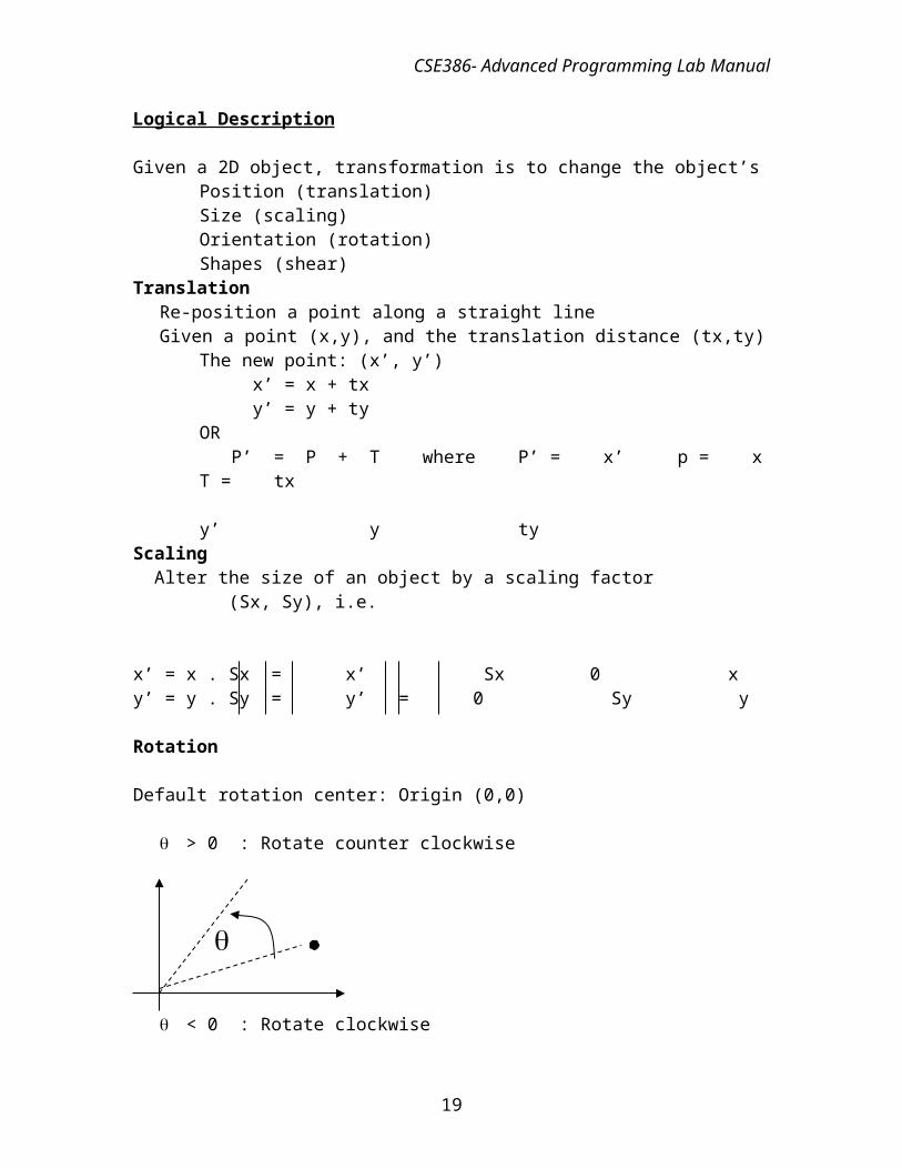
Reflection:
To produce mirror image of an object.
It can be obtained by rotating a object by 180 degree
Y axis
X axis
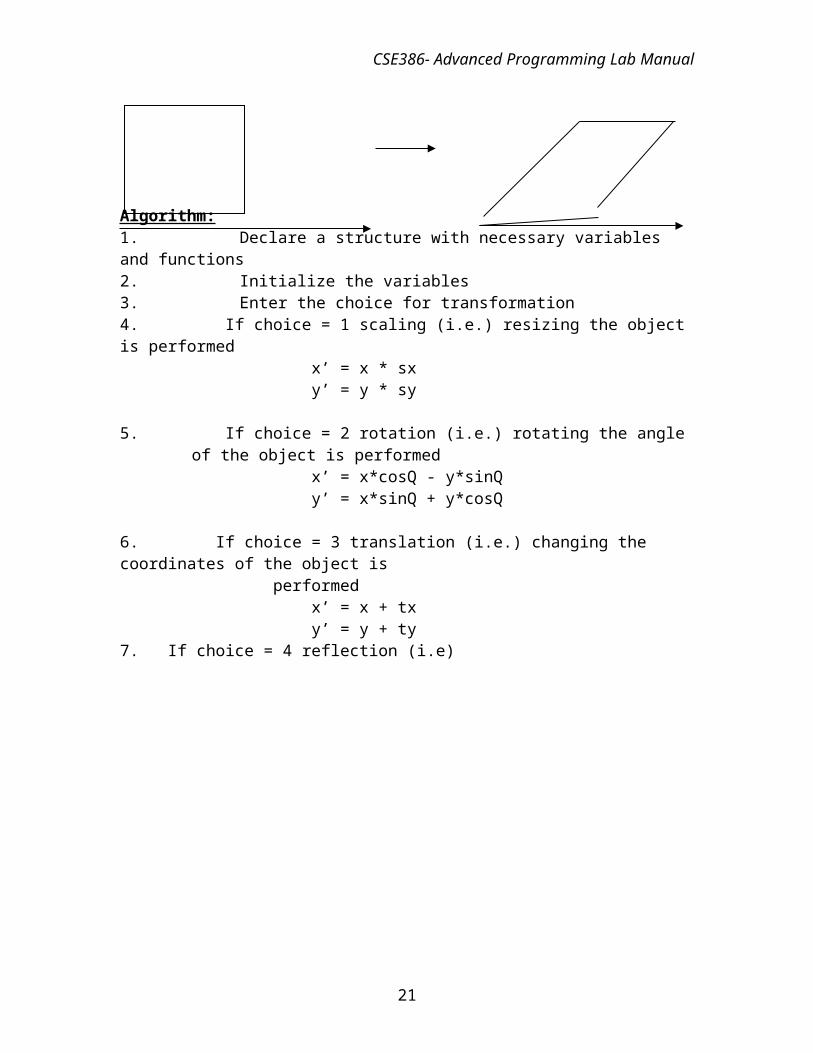
Shearing:
A transformation that distorts the shape of an object.
It can be composed of internal layers that had been caused to slide over each other is called shearing
Algorithm:1. Declare a structure with necessary variables and functions
15
CSE386- Advanced Programming Lab Manual
2. Initialize the variables3. Enter the choice for transformation4. If choice = 1 scaling (i.e.) resizing the object is performed
x’ = x * sx y’ = y * sy
5. If choice = 2 rotation (i.e.) rotating the angle of the object is performedx’ = x*cosQ - y*sinQ y’ = x*sinQ + y*cosQ
6. If choice = 3 translation (i.e.) changing the coordinates of the object is performed
x’ = x + txy’ = y + ty
7. If choice = 4 reflection (i.e)
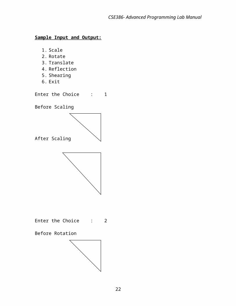
Sample Input and Output:
1. Scale2. Rotate3. Translate4. Reflection5. Shearing6. Exit
Enter the Choice : 1
Before Scaling
After Scaling
16
CSE386- Advanced Programming Lab Manual
Enter the Choice : 2
Before Rotation
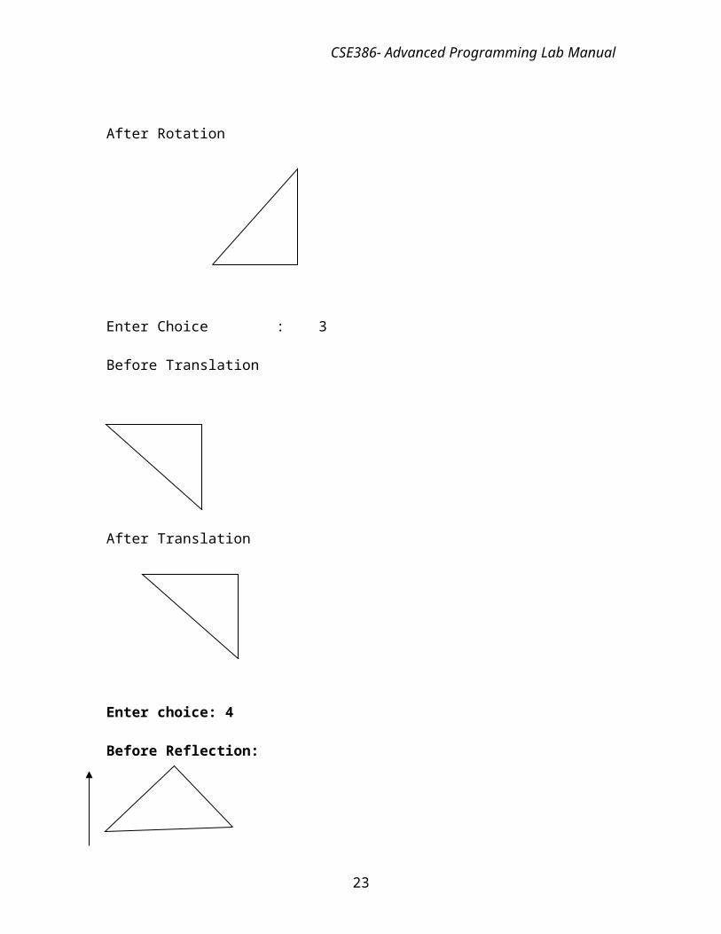
After Rotation
Enter Choice : 3
Before Translation
After Translation
17
CSE386- Advanced Programming Lab Manual
Enter choice: 4
Before Reflection:
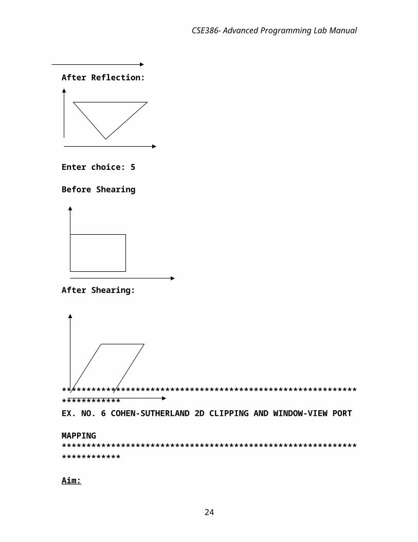
After Reflection:
Enter choice: 5
Before Shearing
After Shearing:
************************************************************************EX. NO. 6 COHEN-SUTHERLAND 2D CLIPPING AND WINDOW-VIEW PORT
18
CSE386- Advanced Programming Lab Manual
MAPPING ************************************************************************
Aim:
To implement line clipping using the line clipping algorithm.
Logical Description:
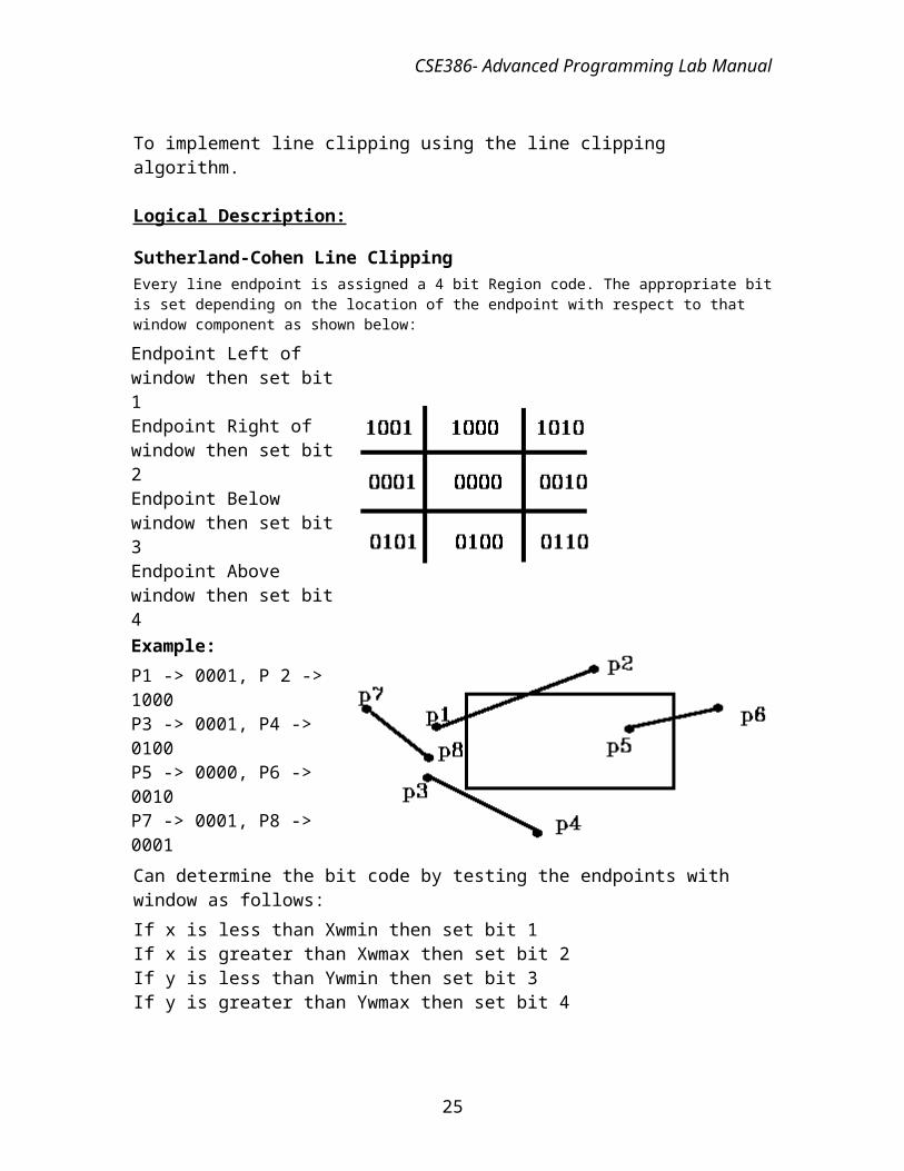
Sutherland-Cohen Line Clipping Every line endpoint is assigned a 4 bit Region code. The appropriate bit is set depending on the location of the endpoint with respect to that window component as shown below:Endpoint Left of window then set bit 1Endpoint Right of window then set bit 2Endpoint Below window then set bit 3Endpoint Above window then set bit 4
Example:P1 -> 0001, P 2 -> 1000P3 -> 0001, P4 -> 0100P5 -> 0000, P6 -> 0010 P7 -> 0001, P8 -> 0001
Can determine the bit code by testing the endpoints with window as follows:If x is less than Xwmin then set bit 1If x is greater than Xwmax then set bit 2If y is less than Ywmin then set bit 3If y is greater than Ywmax then set bit 4We can use 4 element Boolean matrix and set C[Left] = true / false (1/0). If both endpoints = 0000 (in window) then display line. If both endpoints have a bit set in same position (P7, P8) then the line is completely outside the window and is rejected.So: can do logical AND of region codes and reject if result is 0000Can do logical OR of region codes and accept if result = 0000For the rest of the lines we must check for intersection with window. May still be outside, e.g. P3 - P4 in the above image. If point is to Left of window then compute intersection with Left window boundary. Do the same for Right, Bottom, and Top. Then recompute region code restest. So the algorithm is as follows:
1. Compute region code for endpoints
19
CSE386- Advanced Programming Lab Manual
2. Check for trivial accept or reject 3. If step 2 unsuccessful then compute window intersections in order: Left, Right,
Bottom, Top (only do 1) 4. Repeat steps 1, 2,3 until done.
Algorithm:Step 1: First test whether both endpoints are inside (and hence draw the line segment) or
whether both are left of , right of , below ,
or above Step 2: Then ignore line segment. Otherwise split the line segment into two pieces at a
clipping edge and thus reject one part. Now we proceed iteratively. Step 3: A rather simple accept-reject test is the following:
o Bit 1 : outside halfplane of top edge, above top edgeY > Ymax
o Bit 2 : outside halfplane of bottom edge, below bottom edgeY < Ymin
o Bit 3 : outside halfplane of right edge, to the right of right edgeX > Xmax
o Bit 4 : outside halfplane of left edge, to the left of left edgeX < Xmin
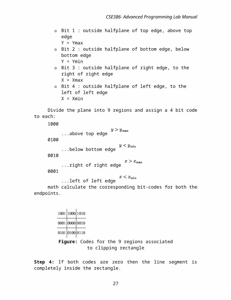
Divide the plane into 9 regions and assign a 4 bit code to each: 1000
...above top edge 0100
...below bottom edge 0010
...right of right edge 0001
...left of left edge math calculate the corresponding bit-codes for both the endpoints.
20
CSE386- Advanced Programming Lab Manual
Figure: Codes for the 9 regions associated to clipping rectangle
Step 4: If both codes are zero then the line segment is completely inside the rectangle. If the bitwise-and of these codes is not zero then the line does not hit since both endpoints lie on the wrong side of at least one boundary line (corresponding to a bit equal to 1).
Step 5: Otherwise take a line which is met by the segment (for this find one non-zero bit), divide the given line at the intersection point in two parts and reject the one lying in the outside half plane.
Sample Input and Output:
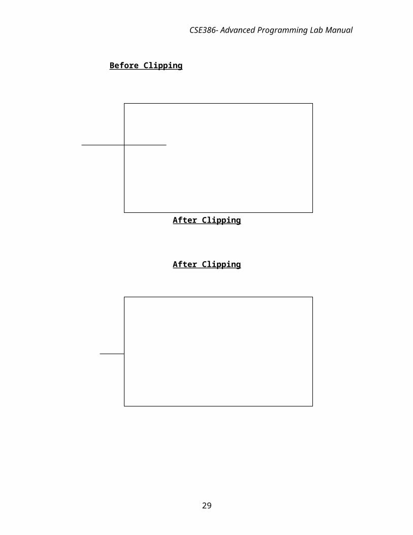
Clipping Window
Before Clipping
21
CSE386- Advanced Programming Lab Manual
After Clipping
After Clipping
**********************************************************************EX. NO. 7 3-D TRANSFORMATIONS
************************************************************************
AIM
22
CSE386- Advanced Programming Lab Manual
To perform the various 3-dimensional transformations such as translation,
scaling, rotation.
Algorithm
Step 1: Input the figure.
Step 2: Display the menu as 1.Translation 2.Scaling 3.Rotation 4.Exit
Step 3: Get the choice from the user.
Step 4: If the choice is 1 a point or an object is translated from position P to position P '
with the operation P'=T.P where tx,ty and tz specifying translation distances.
x'=x+ tx
y'=y+ ty
z'=z+ tz
Step 5: If the choice is 2 the scaling transformation of a position P can be written as
P'=S.P where scaling parameters sx,sy and sz are assigned any positive values.
x'=x.sx
y'=y.sy
z'=z.sz
Step 6: If the choice is 3 get the rotation angle. Rotate the figure with respect to the axis
of rotation.
Step 6a: About z axis rotation
x'=xcosӨ-ysinӨ
y'=xsinӨ+ycosӨ
z'=z
Rotation can be expressed as P'=Rz(Ө).P
Step 6b: About x axis rotation
y'=ycosӨ-zsinӨ
z'=ysinӨ+zcosӨ
x'=x
Rotation can be expressed as P'=Rx(Ө).P
Step 6c: About y axis rotation
z'=zcosӨ-xsinӨ
23
CSE386- Advanced Programming Lab Manual
x'=zsinӨ+xcosӨ
y'=y
Rotation can be expressed as P'=Ry(Ө).P
Step 7: If choice is 4 exit the program.
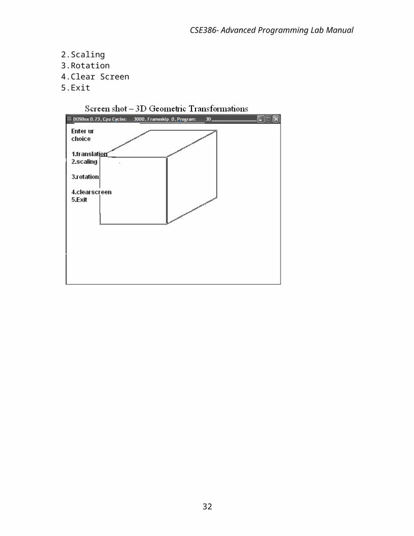
Sample Input/Output :Enter ur Choice1.Translation2.Scaling3.Rotation4.Clear Screen5.Exit
24
CSE386- Advanced Programming Lab Manual
2
25
CSE386- Advanced Programming Lab Manual
3.
26
CSE386- Advanced Programming Lab Manual
************************************************************************
EX. NO. 8 IMPLEMENTATION OF COLOR MODELS
************************************************************************Aim: To implement the color models RGB color in C program
Algorithm:
Step 1: Start the program for color model
Step 2: Include the necessary package.
Step3: Get the Character through getche()function.
Step 4: Depends upon the key value increase the RGB range in appropriate rectangle box using the following functions:
Setrgbpalette(1,R,G,B);
Setfillstyle(1);
bar(x,y,x1,y1);
Rectangle(x1,y1,x2,y2);
Step5: Draw the Color model
Step 6: Finally terminate the color model programSample Input/Output :ENTER UR CHOICE1.RGB TO YIQ2.YIQ TO RGB3.CMY TO RGB4.RGB TO CMY5.EXIT1enter the RGB value234the YIQ value is 2.935000 -0.917000
27
CSE386- Advanced Programming Lab Manual
0.084000ENTER UR CHOICE1.RGB TO YIQ2.YIQ TO RGB3.CMY TO RGB4.RGB TO CMY5.EXIT3enter the CMY value234the RGB value is: -1.000000 -2.000000 -3.000000ENTER UR CHOICE1.RGB TO YIQ2.YIQ TO RGB3.CMY TO RGB4.RGB TO CMY5.EXIT4enter the RGB value -1.000000 -2.000000 .000000the CMY value is: 2.000000 3.000000 4.000000ENTER UR CHOICE1.RGB TO YIQ2.YIQ TO RGB3.CMY TO RGB4.RGB TO CMY5.EXIT2enter the YIQ value234the RGB value is: 6.348000 -3.404000 2.49600
28
CSE386- Advanced Programming Lab Manual
************************************************************************
EX. NO. 9 IMPLEMENTATION OF ANIMATIONS
************************************************************************Aim:To Simulate Car animation and Ball bouncing using C program
Algorithm:
Step 1: Get the coordinates to draw the line,Circle.
Step2:Use floodfill() to fill the circle region.
Step3:To set car in motion get stating point(x,y) values
Step 4:Using putpixel () plot the initial point of car.
Step 5:Increment x& y values to set the car in motion .
Sample Output:
29
CSE386- Advanced Programming Lab Manual
Algoithm:Step1:Get the coordinates to draw circle.
Step2: Use floodfill() to fill the circle region.
Step3:Using line() get boundary region .
Step4:Get values of (x,y) and fix the ball using putpixel(()
Step5:Increment and Decreament (x,y) values to set the ball in motion.
30
CSE386- Advanced Programming Lab Manual
************************************************************************EX. NO. 10 PROJECTIONS OF 3D IMAGES
************************************************************************
AIM
To write a C program to show the perspective projection of a 3D image.
Algorithm
Step1: Get the coordinates to draw the cube.
Step 2: Read the reference point.
Step 3: Read the view plane.
Step 4: For a perspective projection object positions are transformed to the view plane
along lines that converge to a point called the projection reference point.
Step 5: The projected view of an object is determined by calculating the intersection
point of the projection lines with the view plane.
31
CSE386- Advanced Programming Lab Manual
Sample input and output:
32