Embed Size (px)
Citation preview
Bundesstelle fürFlugunfalluntersuchung German Federal Bureau of Aircraft Accident Investigation
Investigation Report Identification
Type of Occurrence: Serious Incident
Date: 3 November 2011
Location: Munich
Aircraft: Transport aircraft
Manufacturer / Model: Boeing / B 777-300 ER
Injuries to Persons: None
Damage: None
Other Damage: Crop damage
State File Number: BFU EX010-11
Investigation Report BFU EX010-11
- 2 -
This investigation was conducted in accordance with the regulation (EU) No. 996/2010 of the European Parliament and of the Council of 20 October 2010 on the investigation and prevention of accidents and incidents in civil aviation and the Federal German Law relat-ing to the investigation of accidents and incidents associated with the operation of civil aircraft (Flugunfall-Untersuchungs-Gesetz - FlUUG) of 26 August 1998. The sole objective of the investigation is to prevent future accidents and incidents. The investigation does not seek to ascertain blame or apportion legal liability for any claims that may arise. This document is a translation of the German Investigation Report. Although every effort was made for the translation to be accurate, in the event of any discrepancies the original German document is the authentic version.
Published by:
Bundesstelle für Flugunfalluntersuchung Hermann-Blenk-Str. 16 38108 Braunschweig
Phone +49 531 35 48 - 0 Fax +49 531 35 48 – 246 Email: [email protected] Internet: www.bfu-web.de
Investigation Report BFU EX010-11
- 3 -
Content Page
Identification .............................................................................................................. 1
Abbreviations ............................................................................................................ 5
Synopsis .................................................................................................................... 7
1. Factual Information ...................................................................................... 8
1.1 History of the Flight ......................................................................................... 8
1.2 Injuries to Persons ........................................................................................ 10
1.3 Damage to Aircraft ........................................................................................ 10
1.4 Other damage ............................................................................................... 10
1.5 Personnel Information ................................................................................... 10
1.5.1 Pilot in Command ......................................................................................... 10
1.5.2 Co-pilot ......................................................................................................... 11
1.5.3 Air Traffic Service Personnel ........................................................................ 12
1.6 Aircraft Information ....................................................................................... 12
1.6.1 Automatic Flight Control System................................................................... 13
1.6.1.2 Operating Mode of the Auto Flight System ............................................... 15
1.7 Meteorological Information ........................................................................... 15
1.8 Aids to Navigation ......................................................................................... 16
1.8.1 Instrument Landing System .......................................................................... 16
1.8.2. ILS dysfunctions due to outer influences ...................................................... 20
1.9 Radio Communications ................................................................................. 22
1.10 Aerodrome Information ................................................................................. 23
1.11 Flight Recorders ........................................................................................... 23
1.12 Wreckage and Impact Information ................................................................ 26
1.13 Medical and Pathological Information ........................................................... 28
1.14 Fire ............................................................................................................... 28
1.15 Survival Aspects ........................................................................................... 28
1.16 Tests and Research ...................................................................................... 28
1.17 Organisational and Management Information ............................................... 29
1.17.1. Air Traffic Service Procedures ...................................................................... 29
1.17.1.1 General National Regulations .................................................................. 30
1.17.1.2 International Regulations .......................................................................... 30
1.17.1.3 ICAO PANS ATM DOC 4444.................................................................... 31
1.17.1.4 ICAO DOC 9365 All Weather Operations ................................................. 31
1.17.1.5 European Regulations .............................................................................. 31
1.17.1.6 Categories for Precision Approaches and Landings ................................. 32
Investigation Report BFU EX010-11
- 4 -
1.17.1.7 Guideline for All-Weather Operations ......................................................... 32
1.17.1.8 Air Traffic Order Para 42 Go-Around ....................................................... 33
1.17.2 Flight Operations of the Operator ................................................................. 33
1.17.2.1 Flight Operations Regulations and Indications ......................................... 33
1.17.3 Procedures of the Aircraft Manufacturer ...................................................... 37
2. Analysis ...................................................................................................... 38
2.1 Technical Aspects ........................................................................................ 38
2.2 Crew Behaviour ............................................................................................ 38
2.3 Relocation of the Instrument Landing System .............................................. 39
2.4 Behaviour of the Air Traffic Controller .......................................................... 40
2.6 Accident Site ................................................................................................ 40
2.7 Automatic Landing ....................................................................................... 40
3. Conclusions ................................................................................................ 42
3.1 Findings ....................................................................................................... 42
3.2 Causes ......................................................................................................... 44
4. Safety Recommendations ......................................................................... 44
5. Appendix ..................................................................................................... 45

Investigation Report BFU EX010-11
- 5 -
Abbreviations
AAL Above Aerodrome Level
AFCS Automatic Flight Control System
AFDC Autopilot Flight Director Computer
AFDS Autopilot Flight Director System
AGIS Air Ground Indication System
AIP Aeronautical Information Publication
AMSL Above Mean Sea Level
ATIS Automatic Terminal Information Service
ATPL Air Transport Pilot's Licence
CET Central European Time
CMC Centralised Monitoring Computer
CRM Crew Resource Management
CSB Carrier Sideband
CVR Cockpit Voice Recorder
DDM Difference in Depth of Modulation
DFS Deutsche Flugsicherung (German Air Traffic Service Provider)
DH Decision Height
DME Distance Measuring Equipment
F/D Flight Director
FCOM Flight Crew Operations Manual
FCTM Flight Crew Training Manual
FDR Flight Data Recorder
FMC Flight Management Computer
GP Glide Path
ICAO International Civil Aviation Organization
ILS Instrument Landing System
Investigation Report BFU EX010-11
- 6 -
KIAS Knots Indicated Airspeed
LIP Line Instructor Pilot
LOC Localizer
LVP Low Visibility Procedures
LW Landing Weight
MCP Mode Control Panel
METAR Meteorological Aerodrome Report
NDB Non Directional Beacon
NfL Nachrichten für Luftfahrer (notices for airmen)
NM Nautical Mile
PF Pilot Flying
PFD Primary Flight Display
PIC Pilot in Command
PM Pilot Monitoring
RVR Runway Visual Range
SBO Side Band Only
SOP Standard Operating Procedures
SPD Speed Mode
TO/GA Take-off/Go-around
TOW Take-off Weight
UTC Universal Time Coordinated
VOR VHF omnidirectional Radio Range
WOW Weight on Wheels

Investigation Report BFU EX010-11
- 7 -
Synopsis
During the landing shortly after touch-down the airplane veered left off the runway,
then crossed the runway and came to a stop on the other side next to the runway.
The serious incident was caused by the following:
Immediate Causes:
The crew decided to conduct an autoland landing even though the conditions
on the ground for a safe conduct were not given.
Shortly before touch-down the airplane was deviated to the left of its flight di-
rection by a disturbed LOC signal. A BAE 146-RJ85 taking off a short distance
ahead of the B 777 caused the interference.
The two pilots could not keep the airplane on the runway after touch-down be-
cause the autopilot was still engaged.
The crew was confused by the behaviour of the airplane. They had not noticed
that the go-around mode had already been deactivated by the initial touch-
down of the left main landing gear.
Systemic Causes:
The recommendation concerning the conduct of autoland landings under
CAT I conditions published in the FCOM of the operator allowed the decision
for an autoland landing without having to consider the required conditions on
the ground.
Investigation Report BFU EX010-11
- 8 -
1. Factual Information
1.1 History of the Flight On 1 November 2011 the crew had conducted the flight from Singapore to Munich.
After a 48-hour stay, on 3 November 2011, the crew conducted the flight from Munich
to Manchester and back. Both pilots stated they had slept well, felt rested, and al-
most adjusted to Central European Time (CET). At 0515 hrs1 the crew reported for
duty. The flight to Manchester occurred without incident. On the subsequent return
flight to Munich 147 passengers, 13 flight attendants and 2 pilots were on board.
According to crew statements the co-pilot was initially Pilot Flying (PF) during the
flight Manchester - Munich. Based on the latest weather information at Munich, visi-
bility 2,000 m, cloud base 300 ft, the Pilot in Command (PIC) decided to assume the
role of PF, as the SOPs (FCOM/NORMAL PROCEDURES/OPERATION) of the op-
erator required, and the co-pilot became Pilot Monitoring (PM). The PIC decided to
conduct an automatic approach and autoland.
At 1152:13 hrs during descent to Flight Level (FL) 110 the crew contacted Munich
approach control for the first time. The crew did not acknowledge receiving the valid
ATIS Information X of 1150 hrs (1050 UTC). The crew received several instructions,
such as heading and rate of descent, from the controller.
At 1158:19 hrs the crew was advised to call Munich Director on frequency
118,825 MHz.
At 1158:42 hrs the crew contacted Munich Director and received heading and de-
scent instructions for the final approach to the Instrument Landing System (ILS) of
runway 08R.
At 1200:43 hrs the crew received the approach clearance to runway 08R "[…] de-
scend 5,000 feet cleared ILS zero eight."
At 1203:23 hrs the crew was instructed to reduce speed to 170 kt and contact Munich
Tower on 120,500 MHz.
1 All times local, unless otherwise stated.

Investigation Report BFU EX010-11
- 9 -
At 1204:37 hrs the crew contacted Munich Tower.
At 1208:47 hrs the crew received the latest wind information and was cleared to land:
“[…] one three zero degrees, seven knots runway zero eight right, cleared to land”.
As the B 777 was about 50 ft above the runway in the flare phase the airplane began
to slowly bank left up to 3.5°. The PIC called out: “Okay, flaps twenty.” At approxi-
mately 420 m beyond the runway threshold the airplane touched down with the left
main landing gear and 132 kt (KIAS). At that time the Auto Flight System (AFS)
switched to rollout mode.
The autopilot was still engaged as the airplane moved toward the left runway edge
and veered off the runway with a speed of 123 kt (KIAS) about 944 m beyond the
threshold in the area of taxiway B4. For about 400 m the airplane rolled through the
grass north of runway 08R in a slightly curved right hand turn. The largest lateral de-
viation from the runway was reached at about 1,242 m beyond the threshold; speed
was 109 kt KIAS. Because of the system design the autopilot disengaged due to
crew inputs via the rudder pedals. The airplane turned right by about 40°, re-entered
the runway close to the intersection with taxiway B6, about 1,566 m beyond the
threshold. The aircraft crossed the runway with a heading of about 120°. Speed was
still 71 kt KIAS. The airplane veered off the runway again, turned left by about 40°,
and came to a stop in the grass south of and parallel to runway 08R. At 1209:09 hrs
the airplane crossed the threshold; at 1209:51 hrs it came to a stop.
According to the pilots there was no need to evacuate the passengers via the slides,
because no one had suffered any injuries and the airplane was apparently not dam-
aged. About two minutes after the airplane had come to a stop the fire brigade ar-
rived at the scene. The passengers disembarked the airplane via two stairs from the
fire brigade.
The crew stated that during the approach and the landing there were no indications
as to malfunctions or system failures. The PIC stated he had tried to initiate a go-
around procedure by pushing the TO/GA buttons on the thrust levers and thereby
triggering the go-around mode once it had been noticed that the airplane banked to
the left. But the airplane did not respond. At the same time he retracted the ground
spoilers manually which had automatically been deployed at the time of the touch-
down.
Investigation Report BFU EX010-11
- 10 -
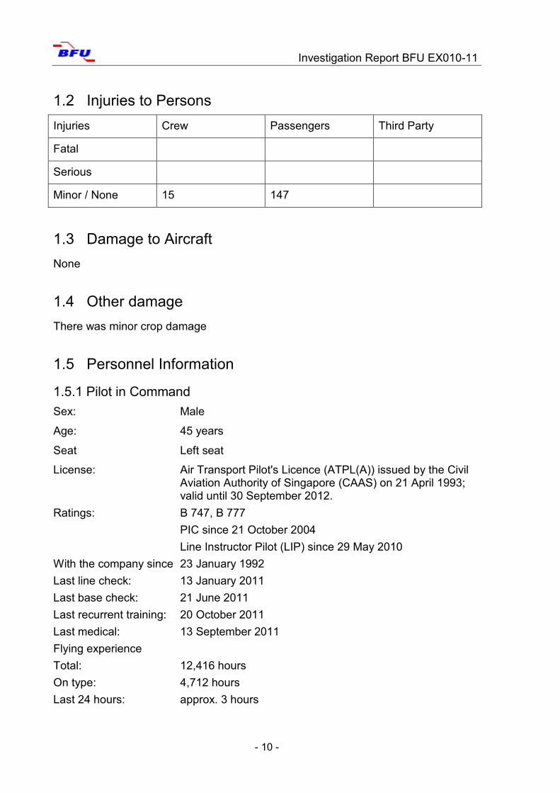
1.2 Injuries to Persons
Injuries Crew Passengers Third Party
Fatal
Serious
Minor / None 15 147
1.3 Damage to Aircraft
None
1.4 Other damage
There was minor crop damage
1.5 Personnel Information
1.5.1 Pilot in Command
Sex: Male
Age: 45 years
Seat Left seat
License: Air Transport Pilot's Licence (ATPL(A)) issued by the Civil Aviation Authority of Singapore (CAAS) on 21 April 1993; valid until 30 September 2012.
Ratings: B 747, B 777
PIC since 21 October 2004
Line Instructor Pilot (LIP) since 29 May 2010
With the company since 23 January 1992
Last line check: 13 January 2011
Last base check: 21 June 2011
Last recurrent training: 20 October 2011
Last medical: 13 September 2011
Flying experience
Total: 12,416 hours
On type: 4,712 hours
Last 24 hours: approx. 3 hours
Investigation Report BFU EX010-11
- 11 -
Last 90 days: 219 hours
Crew Resource Management
Initial Training: 18 March 2005
Recurrent: 6 May 2010
Last day of duty: 1 November 2011 (Singapore – Munich)
Rest period: 48 hours.
1.5.2 Co-pilot
Sex: Male
Age: 35 years
Seat: Right seat
Licence: Air Transport Pilot's Licence (ATPL(A)) issued by the Civil
Aviation Authority of Singapore (CAAS) on
1 February 2008; valid until 29 February 2012
Ratings: B 777
With the company since: 5 September 2002
Last line check: 19 January 2011
Last base check: 8 August 2011
Last recurrent training: 22 November 2010
Last medical: 21 January 2011
Flying experience
Total: 3,681 hours
On type: 3,681 hours
Last 24 hours: Approx. 3 hours
Last 90 days: 182 hours
Crew Resource Management
Initial Training: 16 June 2006
Recurrent: 7 December 2009
Last day of duty: 1 November 2011 (Singapore - Munich)
Rest period: 48 hours
Investigation Report BFU EX010-11
- 12 -
1.5.3 Air Traffic Service Personnel
Approach controller (pick-up)
Sex: Male
Age: 37 years
Licences / Ratings: Approach and area control including Flight Information Ser-
vice; training rating
With the company Since January 1999
At the day of the occurrence a trainee was trained.
Director (feeder)
Sex: Female
Age: 33 years
Licences / Ratings: Approach and area control including Flight Information Ser-
vice; training rating;
With the company Since November 1999 At the day of the occurrence a trainee was trained.
Tower Controller
Sex: Male
Age: 26 years
Licences / Ratings: Aerodrome control with radar including Flight Information
Service;
With the company Since January 2010
1.6 Aircraft Information
Aircraft type: B 777-300 ER
Manufacturer: Boeing Commercial Airplane Group, Seattle,
Washington, USA
Year of manufacture: 2008
Serial number: 34582
Engine: Two General Electric GE90-115B/2-115BL
Maximum Take-off Mass (MTOM): 351,534 kg
Maximum Landing Mass (MLM): 251,291 kg
Investigation Report BFU EX010-11
- 13 -
Actual landing mass: 210,300 kg
Airframe operating hours: 5,539 hours and 25 seconds
The tech log did not list any entries relevant for the serious incident.
The airplane was certified for CAT IIIB approaches with a Runway Visibility Range
(RVR) of 100 m and a Decision Height (DH) of 20 ft.
There were no restrictions concerning the airplane's equipment.
The last autoland was conducted on 26 October 2011 in Singapore.
The last C-check was conducted on 28 November 2010.
1.6.1 Automatic Flight Control System
General Description
The Automatic Flight Control System (AFCS) consists of the Autopilot Flight Director
System (AFDS) and the autothrottle system. Both, AFDS and autothrottle, are oper-
ated via the Mode Control Panel (MCP) and the Flight Management Computer
(FMC). During normal operation the FMC supplies the AFDS with data. The AFDS
controls the airplane during climb, cruise flight, descent, and approach until the land-
ing.
Autopilot Flight Director System
The AFDS consists of three Autopilot Flight Director Computers (AFDCs) and the
Mode Control Panel (MCP).
The MCP provides control of the autopilot, the flight director, the altitude alert, and
the autothrottle system. The MCP is used to select and activate the AFDS modes
and to enter parameters such as altitude, speed, climb and descent profiles. The
Primary Flight Display (PFD) displays the flight director information. The autopilot
controls the elevator, the ailerons, the flaperons and spoilers through the fly-by-wire-
system. The autopilot can control the rudder only during approach and landing. The
autopilot controls the nose wheel steering after an automatic landing.
Engaging the Autopilot
The autopilot is engaged by pushing either one of the two MCP autopilot engage
switches.
Disengaging the Autopilot
Investigation Report BFU EX010-11
- 14 -
During normal operation the autopilot can be disengaged via the autopilot disconnect
switch on either of the two control columns. The autopilot can also be disengaged on
the MCP autopilot disengage bar.
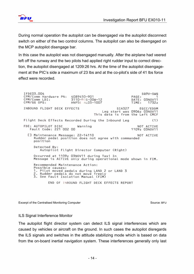
In this case the autopilot was not disengaged manually. After the airplane had veered
left off the runway and the two pilots had applied right rudder input to correct direc-
tion, the autopilot disengaged at 1209:26 hrs. At the time of the autopilot disengage-
ment at the PIC’s side a maximum of 23 lbs and at the co-pilot’s side of 41 lbs force
effect were recorded.
ILS Signal Interference Monitor
The autopilot flight director system can detect ILS signal interferences which are
caused by vehicles or aircraft on the ground. In such cases the autopilot disregards
the ILS signals and switches in the attitude stabilizing mode which is based on data
from the on-board inertial navigation system. These interferences generally only last
Excerpt of the Centralised Monitoring Computer Source: BFU
Investigation Report BFU EX010-11
- 15 -
for short periods of time and no error is indicated. If the interferences last longer the
flight director mode is downgraded from LAND3 or LAND2, for example.
1.6.1.2 Operating Modes of the Auto Flight System
Flare Mode
During an autoland the airplane in flare mode is guided toward the ground in a slight
flare curve. The flare mode is only active if the PFD indicates LAND2 or LAND3 and
starts about 50 ft above the runway. Between 50 ft and 25 ft the thrust levers are au-
tomatically pulled into idle. On the PFD the indication changes from SPD to IDLE. Af-
ter touch-down of the nose landing gear on the runway the indication on the PFD
changes from Flare into Rollout Mode.
Rollout Mode
The rollout mode is armed when the airplane is at about 1,500 ft radio height and be-
comes active once the aircraft is below 2 ft above the runway. After touch-down the
autoflight system uses rudder and nose wheel steering to follow the localizer signal.
Go-Around Mode
The automatic go-around mode is on stand-by when the flaps are beyond their neu-
tral position or the ILS glide slope is activated. The automatic go-around becomes
active once one of the two push switches on the thrust levers (TO/GA button) is
pushed.
The manufacturer stated that the go-around mode is deactivated when the AFDC
logic signals that the airplane is on the ground. This logic takes into account the radio
height and the Weight on Wheels (WOW) signal from the Air Ground Indication Sys-
tem (AGIS). The autopilot calculates the height of the landing gear based on the ra-
dio altitude and the aircraft geometry. The calculated landing gear height has to be
less than 2 ft and the left or right WOW signal has to be present.
1.7 Meteorological Information
Until 0920 UTC fog and visibilities between 600 and 900 m prevailed at Munich Air-
port. After 0940 UTC visibility improved slowly to 2,000 m at the time of the landing.
Prior to landing, the crew had received two aviation routine weather reports (METAR)
via the Air Traffic Information Service (ATIS) Munich. Information W of 1030 UTC and
Information X of 1050 UTC included:
Investigation Report BFU EX010-11
- 16 -
Slight wind from easterly directions with 8 kt; visibility 2 km with light mist. Cloud base
at 300 ft, partially descending to 200 ft. Temperature and dewpoint were 4°C. Baro-
metric air pressure was 1,011 hPa. No significant weather changes were to be ex-
pected.
1.8 Aids to Navigation
For the approach to runway 08R an Instrument Landing System (ILS), a Distance
Measuring Equipment (DME), a Non-Directional Beacon (NDB), and an Omnidirec-
tional Radio Beacon (VOR) were available. The ILS used the frequency 109.3 MHz
with the identifier IMSE and had a glide slope of 3°. The ILS glide slope transmitter
(GP) was a GP 422 dual-frequency system manufactured by Thales.
The ILS localizer (LOC) was a LOC 421 dual-frequency system manufactured by
Thales. The system had been installed in May 2010. The location of the antenna had
been changed to about 650 m farther east of the old location which means about
1,000 m from the end of runway 08R. Initial survey took place between 8 and 12 May
2010. On 31 May 2010 the technical clearance for CAT I occurred. The technical
clearance to CAT II and CAT III occurred on 28 July 2010 and the operational clear-
ance on 3 August 2010. Technical clearance to CAT II and CAT III occurred on
28 July 2010 and operational clearance on 3 August 2010.
On 20 October 2011 the Aeronautical Information Publication (AIP) published these
changes on the respective aerodrome chart. The pages AD 2 EDDM 1-9 Radio Navi-
gation and Landing Aids still showed the coordinates for the old location of the an-
tenna.
The last recurring calibration flight took place on 17 May 2011. The calibration record
was made available to the BFU.
1.8.1 Instrument Landing System
The ILS is a radio-navigation system and basically consists of ground based localizer
and glide slope systems and the respective receivers and indicators on board an air-
craft. The localizer provides the indication of the deviation from the extended runway
centre line for the approaching airplane; the glide slope provides signals for the indi-
cation of the deviation from the optimal descent profile to the touch-down point. This
part of the system does not play any part in further considerations.
Investigation Report BFU EX010-11
- 17 -
Purpose of the Localizer
The localizer generates and emits high-frequency signals which provide course guid-
ance to the runway during the approach. The localizer also provides course guidance
during rollout if equipment and runways are certified for all-weather operations in ac-
cordance with CAT III.
Course and Clearance
The deviation from the extended runway centre line indicated in the aircraft is de-
duced from an angular information: the indication varies depending on the difference
between the direction of the extended runway centre line and the direction of the pre-
vailing flight direction in relation to the localizer antenna. Therefore, the displacement
sensitivity of the indication, in regard to the absolute deviation, is in reverse propor-
tion to the distance to the antenna.
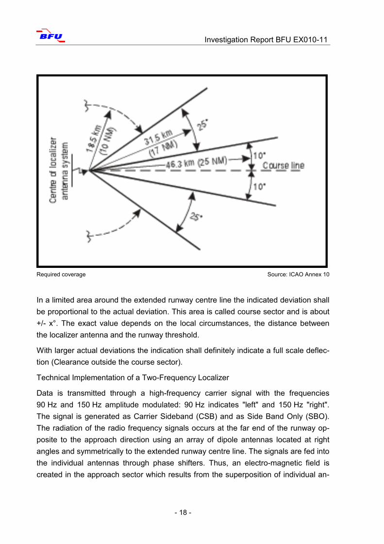
ICAO Annex 10 requires a coverage, i.e. a clear indication, [...] The localizer cover-
age sector shall extend from the centre of the localizer antenna system to distances
of: 46.3 km (25 NM) within plus or minus 10 degrees from the front course line;
31.5 km (17 NM) between 10 degrees and 35 degrees from the front course line [...].
Investigation Report BFU EX010-11
- 18 -
In a limited area around the extended runway centre line the indicated deviation shall
be proportional to the actual deviation. This area is called course sector and is about
+/- x°. The exact value depends on the local circumstances, the distance between
the localizer antenna and the runway threshold.
With larger actual deviations the indication shall definitely indicate a full scale deflec-
tion (Clearance outside the course sector).
Technical Implementation of a Two-Frequency Localizer
Data is transmitted through a high-frequency carrier signal with the frequencies
90 Hz and 150 Hz amplitude modulated: 90 Hz indicates "left" and 150 Hz "right".
The signal is generated as Carrier Sideband (CSB) and as Side Band Only (SBO).
The radiation of the radio frequency signals occurs at the far end of the runway op-
posite to the approach direction using an array of dipole antennas located at right
angles and symmetrically to the extended runway centre line. The signals are fed into
the individual antennas through phase shifters. Thus, an electro-magnetic field is
created in the approach sector which results from the superposition of individual an-
Required coverage Source: ICAO Annex 10
Investigation Report BFU EX010-11
- 19 -
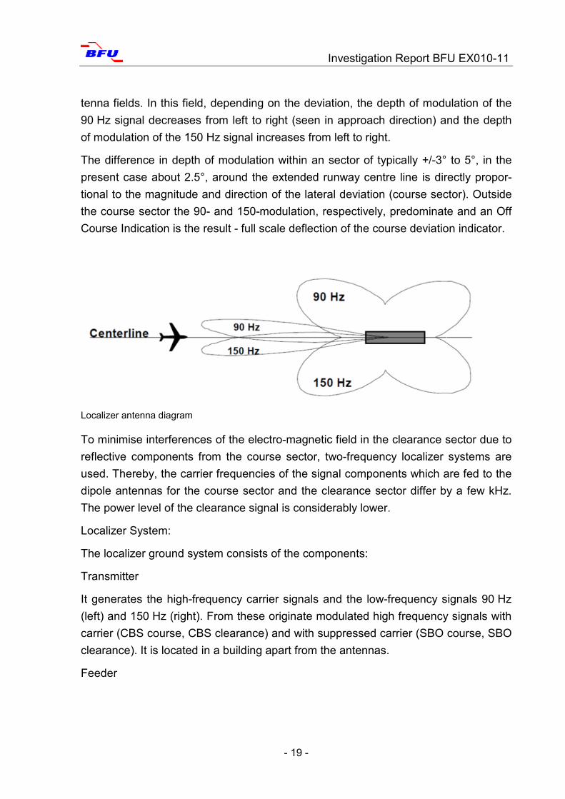
tenna fields. In this field, depending on the deviation, the depth of modulation of the
90 Hz signal decreases from left to right (seen in approach direction) and the depth
of modulation of the 150 Hz signal increases from left to right.
The difference in depth of modulation within an sector of typically +/-3° to 5°, in the
present case about 2.5°, around the extended runway centre line is directly propor-
tional to the magnitude and direction of the lateral deviation (course sector). Outside
the course sector the 90- and 150-modulation, respectively, predominate and an Off
Course Indication is the result - full scale deflection of the course deviation indicator.
To minimise interferences of the electro-magnetic field in the clearance sector due to
reflective components from the course sector, two-frequency localizer systems are
used. Thereby, the carrier frequencies of the signal components which are fed to the
dipole antennas for the course sector and the clearance sector differ by a few kHz.
The power level of the clearance signal is considerably lower.
Localizer System:
The localizer ground system consists of the components:
Transmitter
It generates the high-frequency carrier signals and the low-frequency signals 90 Hz
(left) and 150 Hz (right). From these originate modulated high frequency signals with
carrier (CBS course, CBS clearance) and with suppressed carrier (SBO course, SBO
clearance). It is located in a building apart from the antennas.
Feeder
Localizer antenna diagram
Investigation Report BFU EX010-11
- 20 -
Through phase splitters or dispatchers, respectively, the four signal parts are fed to
the antennas. The phase and amplitude relations of the signal components to each
other for each dipole of the antenna array are set.
Antenna Array
The antenna array consists of a row of dipole antennas which are located at right an-
gles and symmetrically to the runway. In general, the antennas are located about
300 m to 400 m beyond the end of the runway; in this case it was approximately
1,000 m.
Near Field Monitor
It consists of antenna, receiver and signal analysis. Its antenna is located some 10 m
ahead of the localizer antennas. The near field monitor monitors the localizer signal
to detect possible corruption due to dysfunctional system components. The near field
monitor is not mandatory.
Far Field Monitor
It, too, consists of antenna, receiver and signal analysis. Its antenna is located some
km ahead of the localizer antennas often prior to the beginning of the runway in the
area of the approach lighting. The far field monitor monitors the localizer signal to de-
tect possible corruption coming from the area of the runway and its surroundings, e.
g. signal reflections. The far field monitor is mandatory for the all-weather operations
CAT II and CAT III.
Integral Monitor
In the antenna array the emitted signals are probed via sensors, recombined into
signal components and monitored.
Monitoring System
It signals and records, respectively, the disturbances detected by the near field, the
far field and integral monitors and either shuts down the system or switches to the
back-up transmitter.
1.8.2. ILS Dysfunctions due to Outside Influences
Antenna Characteristics
The antenna characteristics describe the directionality of the radiation viewed from
the antenna.
Investigation Report BFU EX010-11
- 21 -
The electromagnetic field of the localizer transmitter antenna originates from the su-
perposition of the four signal components, CSB and SBO for the course sector and
the CSB and SBO for the clearance sector (see chapter Technical Realisation) which
are fed to the antenna components via adjusted phase shifters.
Due to the phase-shifted and amplitude adjusted feed-in, each of the four signal
components has its own antenna characteristic; the superposition of these character-
istics constitutes the antenna radiation pattern.
The relation between the DDM of the signal received on board the aircraft and the
lateral deviation from the extended runway centre line is required to be proportional.
This is achieved with a zero within the antenna characteristic of the SBO component
for the course sector.
Therefore originating from this signal component no power is radiated along the cen-
tre line. However in the proximity of the centre line the radiated power increases sub-
stantially, even if the lateral deviation is small compared to the width of the course
sector.
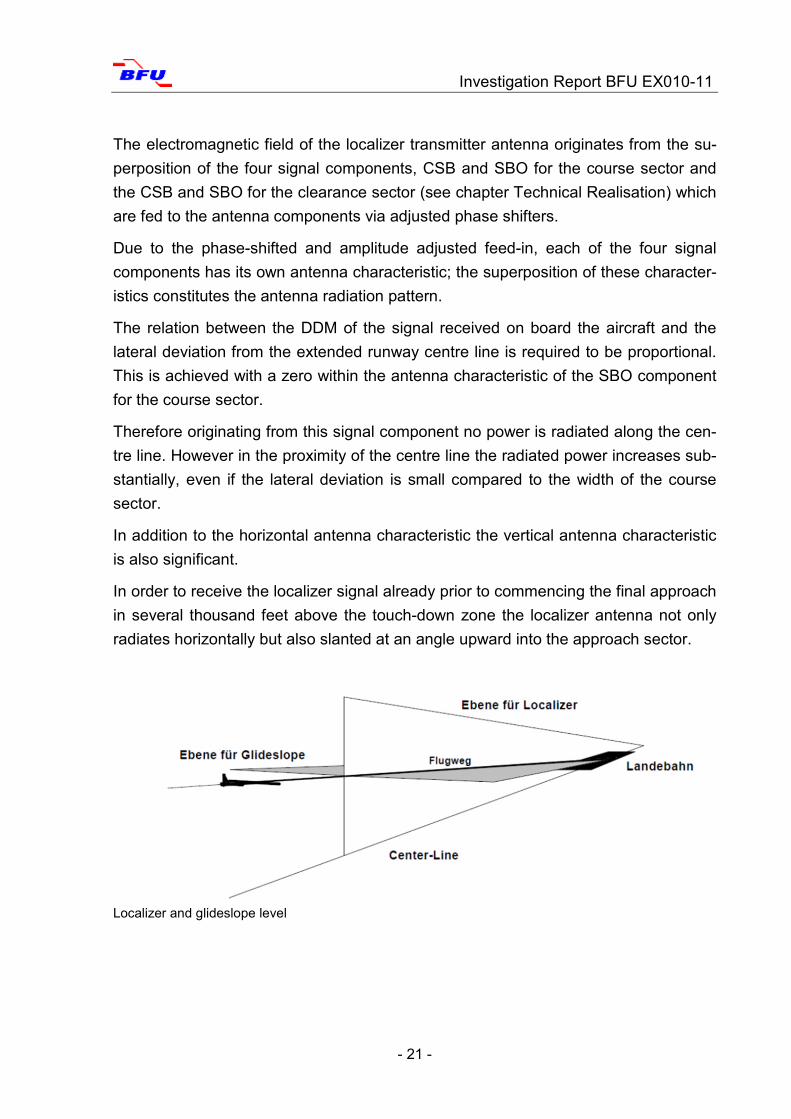
In addition to the horizontal antenna characteristic the vertical antenna characteristic
is also significant.
In order to receive the localizer signal already prior to commencing the final approach
in several thousand feet above the touch-down zone the localizer antenna not only
radiates horizontally but also slanted at an angle upward into the approach sector.
Localizer and glideslope level
Investigation Report BFU EX010-11
- 22 -
Electromagnetic Interference
Basically electromagnetic waves propagate in a straight line. This can be affected by:
Refraction - is the change in direction of a wave due to a change in its trans-
mission medium (while propagating in an inhomogeneous medium it is bend
toward the denser area).
Diffraction - waves are bend around edges.
Diffusion - radiation originally propagating in one direction is being diffused by
an object and then propagates in different directions.
Reflection - whenever radiation meets a plain or slightly bent surface it is be-
ing refracted (like a mirror).
Interference Sources
Surfaces and edges of objects affect the propagation of electromagnetic waves. Me-
tallic surfaces have a special importance due to their electromagnetic characteristics.
Objects in the area of the extended runway centre line are directly in the propagation
path from the localizer antenna to the approaching or rolling-out aircraft.
Outside the course sector full scale deflection of the course deviation indicator is re-
quired and in order to ensure it, electromagnetic energy is also radiated in areas
which are further away from the extended runway centre line.
Sources of interference can therefore be:
Buildings such as terminals, hangars, antenna support and masts
Aircraft and other vehicles on the ground
Aircraft flying ahead in the area of the approach path or above the approach
path.
They can be divided in stationary and moving sources of interference (e.g. hangar
doors, airplanes, vehicles, etc.).
1.9 Radio Communications
Radio communications in English were initially conducted on frequency
118.825 MHz, Munich Director, and later on frequency 120.5 MHz, Munich Tower.
The BFU received transcripts of the recorded radio communications.
Investigation Report BFU EX010-11
- 23 -
1.10 Aerodrome Information
Munich Airport is located 28.5 km north-east of Munich at an aerodrome elevation of
1,487 ft AMSL. It has two parallel 4,000-meter-long runways each with a width of
60 m. Their true bearings are 082° and 262°, respectively. The lateral distance be-
tween the two runways is 2,280 m.
Runway 08R has a grooved concrete surface. At the time of the landing, the runway
was dry and braking action good.
All runways were equipped with an instrument landing system for all-weather opera-
tions up to CAT IIIb.
The installation of the instrument landing system for runway 08R was conducted in
accordance with the guide line for the installation of ILS equipment dated
1 July 2008, version 2.2. It corresponded with ICAO Annex 10, Chapter 3, Specifica-
tions for Radio Navigation Aids.
The ILS was subject to continuous control. Regular calibration flights or surface sur-
veys were conducted.
1.11 Flight Recorders
The Flight Data Recorder (FDR) and the Cockpit Voice Recorder (CVR) were re-
moved from the airplane in the presence of the BFU and transported to Braun-
schweig for analysis.
The FDR was a Honeywell Solid State Flight Data Recorder (SSFDR) with the part
number 980-4700-042 and the serial number 14429. It can record 1,312 parameters.
The CVR was a Honeywell Solid State Cockpit Voice Recorder (SSCVR); it had five
recording channels of 3 x 30 minutes and 2 x 120 minutes recording capacity.
The recordings of the aerodrome surface movement radar were seized and analysed
at the BFU.
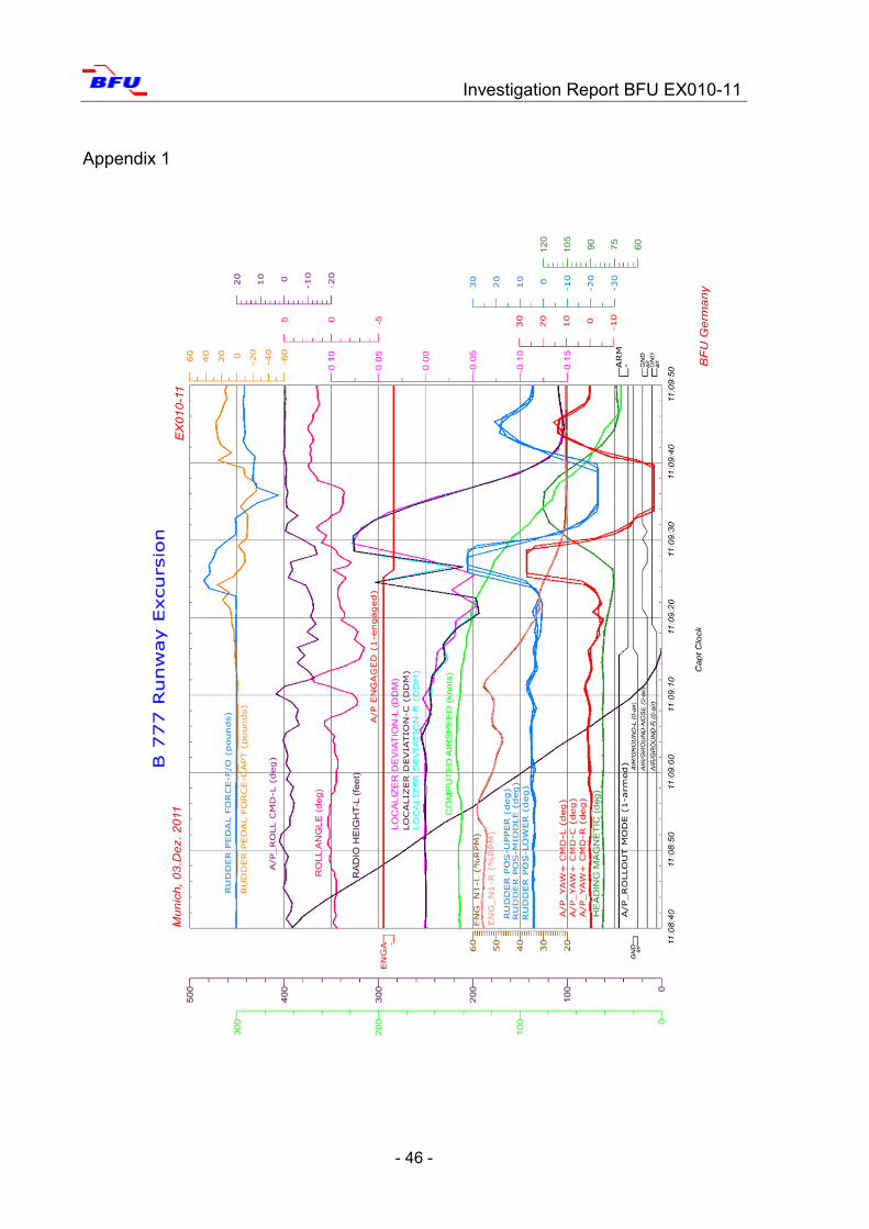
The analysis of the FDR determined (Appendix 1):
Until 1209:00 hrs (1109:00 UTC) approach occurred without incidents. Between
1209:02 hrs (altitude about 110 ft) and 1209:10 hrs (altitude about 30 ft) the three
parallel working localizer antennas on board the airplane recorded signals which
showed an irregular beam deviation. From 1209:10 hrs on signals were recorded
Investigation Report BFU EX010-11
- 24 -
which showed an increasing beam deviation from the extended runway centre line or
runway centre line, respectively, towards the right.
The airplane began to roll to the left and on touch-down reached a maximum bank
angle of 3.5°. At 1209:16 hrs the airplane touched down with the left main landing
gear, three seconds later the right main landing gear followed and a further two sec-
onds later the nose landing gear touched down on the runway.
At the time the autopilot was still engaged; the localizer mode changed to rollout
mode.
The autopilot followed the LOC signal with rudder inputs and steered the airplane left.
According to the FDR data, at about 1109:18 UTC the PIC began to apply the right
rudder to keep the airplane on the runway. At this time the autopilot was still engaged
and therefore the control inputs remained ineffective.
According to FDR data at 1209:23 hrs the co-pilot also applied right rudder pedal in-
put. At 1209:23 hrs the airplane veered off the runway.
The maximum recorded force on the pedal was 23 lbs on the PIC's side and 41 lbs
on the co-pilot's. Immediately afterwards, the autopilot disengaged.
At 1209:28 hrs the airplane reached the largest lateral deviation from the runway
centre line.
Between 1209:16 hrs and 1209:24 hrs the ground spoilers deployed briefly and re-
tracted again.
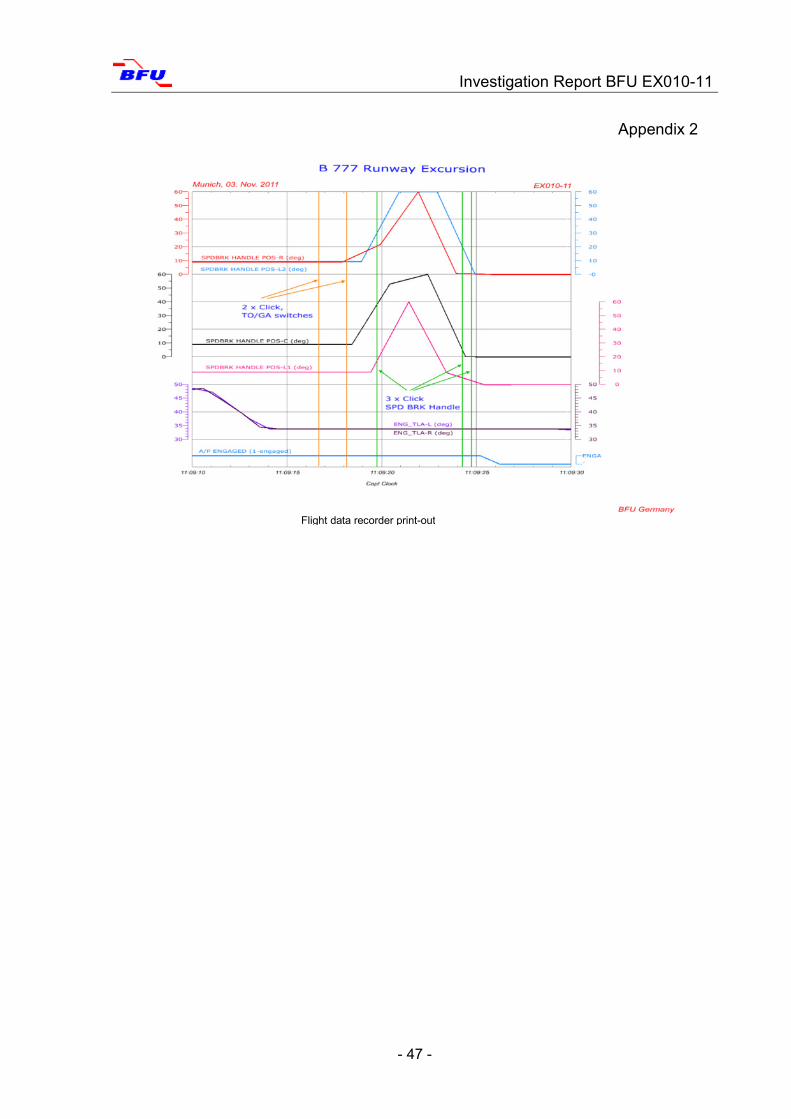
The FDR did not show any indications for the initiation of a go-around procedure.
However, at the time of the touch-down the CVR recorded the PIC's command "okay,
flaps twenty" together with several sounds which indicate the clicking of the TO/GA
button and the movement of speed brake handle.
Preparation of a Sonogram:
The BFU compiled a sonogram in order to analyse the sounds recorded on the CVR
and assign them with crew actions at the time of touchdown. The first two sounds in
the sonogram could be from pushing the TO/GA buttons. The subsequent three
sounds could be from the activation of the speed brake handle (deploying and re-
tracting the speed brakes). It could confirm the crew's statement that the PIC had
tried to initiate a go-around procedure; it is not an unambiguous proof, however.
Investigation Report BFU EX010-11
- 25 -
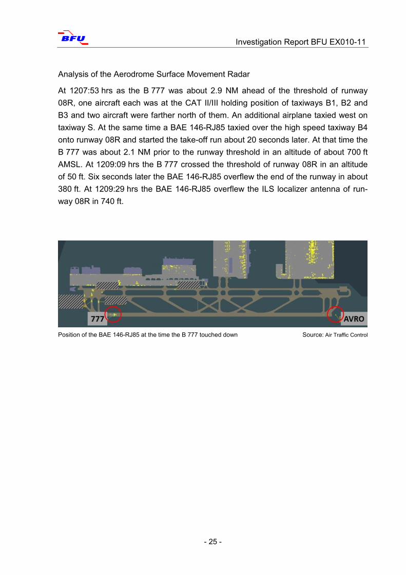
Analysis of the Aerodrome Surface Movement Radar
At 1207:53 hrs as the B 777 was about 2.9 NM ahead of the threshold of runway
08R, one aircraft each was at the CAT II/III holding position of taxiways B1, B2 and
B3 and two aircraft were farther north of them. An additional airplane taxied west on
taxiway S. At the same time a BAE 146-RJ85 taxied over the high speed taxiway B4
onto runway 08R and started the take-off run about 20 seconds later. At that time the
B 777 was about 2.1 NM prior to the runway threshold in an altitude of about 700 ft
AMSL. At 1209:09 hrs the B 777 crossed the threshold of runway 08R in an altitude
of 50 ft. Six seconds later the BAE 146-RJ85 overflew the end of the runway in about
380 ft. At 1209:29 hrs the BAE 146-RJ85 overflew the ILS localizer antenna of run-
way 08R in 740 ft.
Position of the BAE 146-RJ85 at the time the B 777 touched down Source: Air Traffic Control
Investigation Report BFU EX010-11
- 26 -
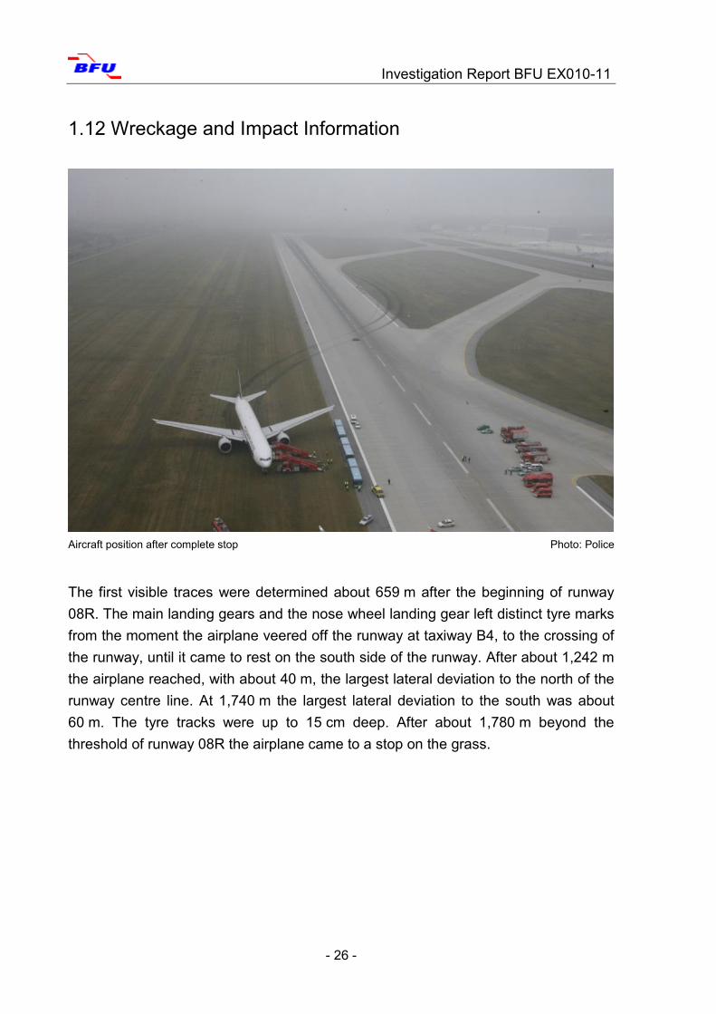
1.12 Wreckage and Impact Information
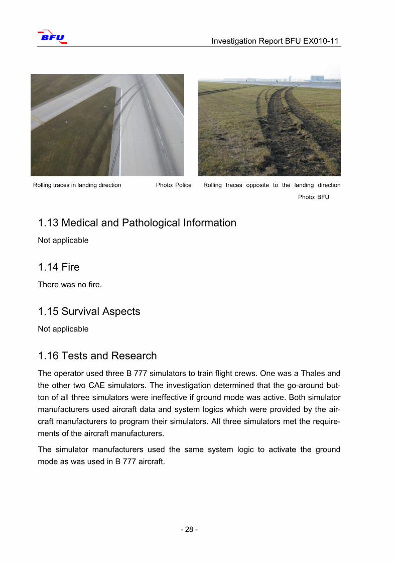
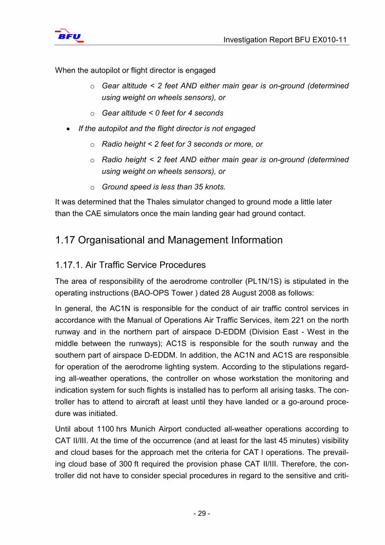
The first visible traces were determined about 659 m after the beginning of runway
08R. The main landing gears and the nose wheel landing gear left distinct tyre marks
from the moment the airplane veered off the runway at taxiway B4, to the crossing of
the runway, until it came to rest on the south side of the runway. After about 1,242 m
the airplane reached, with about 40 m, the largest lateral deviation to the north of the
runway centre line. At 1,740 m the largest lateral deviation to the south was about
60 m. The tyre tracks were up to 15 cm deep. After about 1,780 m beyond the
threshold of runway 08R the airplane came to a stop on the grass.
Aircraft position after complete stop Photo: Police

Investigation Report BFU EX010-11
- 27 -
There were no damages on the airplane safe for some grass and dirt on the right en-
gine and the landing gear.
Rolling traces of the airplane Source: Munich Airport
Right main landing gear and contamination on the right engine Photos: BFU
Investigation Report BFU EX010-11
- 28 -
Rolling traces in landing direction Photo: Police Rolling traces opposite to the landing direction
Photo: BFU
1.13 Medical and Pathological Information
Not applicable
1.14 Fire
There was no fire.
1.15 Survival Aspects
Not applicable
1.16 Tests and Research
The operator used three B 777 simulators to train flight crews. One was a Thales and
the other two CAE simulators. The investigation determined that the go-around but-
ton of all three simulators were ineffective if ground mode was active. Both simulator
manufacturers used aircraft data and system logics which were provided by the air-
craft manufacturers to program their simulators. All three simulators met the require-
ments of the aircraft manufacturers.
The simulator manufacturers used the same system logic to activate the ground
mode as was used in B 777 aircraft.
Investigation Report BFU EX010-11
- 29 -
When the autopilot or flight director is engaged
o Gear altitude < 2 feet AND either main gear is on-ground (determined
using weight on wheels sensors), or
o Gear altitude < 0 feet for 4 seconds
If the autopilot and the flight director is not engaged
o Radio height < 2 feet for 3 seconds or more, or
o Radio height < 2 feet AND either main gear is on-ground (determined
using weight on wheels sensors), or
o Ground speed is less than 35 knots.
It was determined that the Thales simulator changed to ground mode a little later
than the CAE simulators once the main landing gear had ground contact.
1.17 Organisational and Management Information
1.17.1. Air Traffic Service Procedures
The area of responsibility of the aerodrome controller (PL1N/1S) is stipulated in the
operating instructions (BAO-OPS Tower ) dated 28 August 2008 as follows:
In general, the AC1N is responsible for the conduct of air traffic control services in
accordance with the Manual of Operations Air Traffic Services, item 221 on the north
runway and in the northern part of airspace D-EDDM (Division East - West in the
middle between the runways); AC1S is responsible for the south runway and the
southern part of airspace D-EDDM. In addition, the AC1N and AC1S are responsible
for operation of the aerodrome lighting system. According to the stipulations regard-
ing all-weather operations, the controller on whose workstation the monitoring and
indication system for such flights is installed has to perform all arising tasks. The con-
troller has to attend to aircraft at least until they have landed or a go-around proce-
dure was initiated.
Until about 1100 hrs Munich Airport conducted all-weather operations according to
CAT II/III. At the time of the occurrence (and at least for the last 45 minutes) visibility
and cloud bases for the approach met the criteria for CAT I operations. The prevail-
ing cloud base of 300 ft required the provision phase CAT II/III. Therefore, the con-
troller did not have to consider special procedures in regard to the sensitive and criti-
Investigation Report BFU EX010-11
- 30 -
cal areas for runway 08R. Due to the prevailing weather the increased separation
minima which are required for CAT II/III did not have to be applied.
Use of the ILS
It is known that ILS (localizer and glide slope) are very sensitive to outer influences.
Different reports from different operators indicate that during autoland approaches
under CAT I conditions the localizer and/or glide slope can dysfunction due to air-
planes taking off or vehicles on the ground which may lead to a critical situation for
approaching airplanes.
1.17.1.1 General National Regulations
In accordance with the guidelines for all-weather operations (NfL I/1-99 in combina-
tion with NfL I/188-10) Low Visibility Procedures (LVP) are applied when the following
conditions prevail: a Runway Visibility Range (RVR) of less than or equal to 600 m
and/or a cloud base of 200 ft. Under the above-mentioned conditions and as soon as
the approaching airplane is within 2 NM ahead of the runway threshold, the separa-
tion between an approaching aircraft and another approaching or departing airplane
has to be such that the ILS signals will not be distorted by departing or approaching
aircraft. Item 5.7.2 of the NfL stipulates that during approaches (also trainings) under
better weather conditions than CAT II or CAT III the pilot has to specifically request
the application of all-weather operations on the ground if the higher (more restrictive)
category is desired. The air traffic control unit informs the pilot if and with which re-
strictions all-weather operations on the ground can be conducted. The stipulations
published in the guidlines for all-weather operations are in accordance with the Man-
ual of Operations Air Traffic Services (MO-ATS) of 2011.
1.17.1.2 International Regulations
Excerpt EUR DOC 13 "Third Edition" (June 2008):
Item 6.1.1 The type of operations that may be considered in Low Visibility Conditions
are departure operations in RVR conditions less than a value of 550 m and CAT II
and CAT III approach and landing operations. The primary focus for developing these
procedures must be a safety driven exercise to ensure the protection of the runway
and of the guidance signals […]
Item 6.8.3: Autoland operations when LVP are not in operation: When LVP are not in
operation, it is possible that aircraft and vehicles may cause disturbance to ILS sig-
nal. This may result in sudden and unexpected flight control movements at very low
Investigation Report BFU EX010-11
- 31 -
altitude or during the landing and rollout when the autopilot attempts to follow the
beam bends. As a result pilots are advised to exercise caution during these opera-
tions according to the instructions provided in their operation manual.
EUR DOC 013 Draft 8 of the Fourth Edition Items 7.5.6.1.1.12 and 13 stipulate this.
1.17.1.3 ICAO PANS ATM DOC 4444
Item 7.12.5. f 2. stipulates the following:
Provisions regarding low visibility operations should specify special procedures for
the control of traffic on the maneuvering area, including the minimum distance be-
tween an arriving and a departing aircraft to ensure protection of the sensitive and
critical area.
These stipulations were implemented with the publication of the guideline for all-
weather operations and the Manual of Operations Air Traffic Services (MO-ATS).
1.17.1.4 ICAO DOC 9365 All Weather Operations
This document is to be viewed as guideline not as standard or recommended prac-
tices.
Item 3.2.7 stipulates the following:
Critical areas must be protected if the weather conditions are less than 250 m (800 ft)
cloud base or 3,000 m visibility when instrument approach operations are being car-
ried out.
ILS critical and sensitive areas must always be protected if the weather conditions
are lower than 60 m (200 ft) cloud base or 600 m RVR when instrument approach
operations are being carried out. In the latter case, aircraft which will overfly the
localizer transmitter antenna after take-off should be passed the antenna be-
fore an aircraft making an approach has descended to a height of 60 m (200 ft)
above the runway […]
1.17.1.5 European Regulations
European Interim Guidance Material on Management of ILS Localizer critical and
sensitive Areas.
Departure-Arriving Operations
Investigation Report BFU EX010-11
- 32 -
Departing aircraft may cause short-time ILS signal distortions due to shadowing ef-
fects by the aircraft body. These fluctuations are considered acceptable in CAT I op-
erations. This is applicable irrespective of arriving aircraft position.
1.17.1.6 Categories for Precision Approaches and Landings
For ILS precision approaches and landings, the guideline for all-weather operations
of 13 November 1998 of the Deutsche Flugsicherung (German air traffic service pro-
vider, DFS) stipulates the following categories:
Category I (CAT I)
Approaches and landings at a decision height of not less than 200 ft and a RVR of
not less than 550 m; if a RVR is not available than a RVR of not less than 550 m cal-
culated from the meteorological visibility.
Category II (CAT II)
Approaches and landings at a decision height of less than 200 ft but not less than
100 ft and a RVR of not less than 300 m.
Category IIIa (CAT IIIa)
Approaches and landings at a decision height of less than 100 ft but not less than 50
ft and a RVR of not less than 200 m.
Category IIIb (CAT IIIb)
and landings at a decision height of less than 50 ft or without any decision height and
a RVR of less than 200 m but not less than 75 m.
Category IIIc (CAT IIIc)
Approaches and landings without decision height and no minimum RVR.
1.17.1.7 Guideline for All-Weather Operations
Item 5.2 stipulates the following:
If a RVR of 600 m is reached or infringed and or the cloud base of 200 ft is infringed
ATIS will broadcast that CAT II is in operation on the ground with the wording "Low
Visibility Procedures CAT II in Operation. The visual approach slope indicator and the
electronic flash approach lighting is deactivated.
5.2.1 At RVR of 400 m at the latest, the stop bars and runway centre line lighting are
activated. If the are no stop bar, the protection of the runway for unintended line-up is
to be ensured.
Investigation Report BFU EX010-11
- 33 -
5.2.2 Provision of Low Visibility Take-Off procedures (LVTO) is broadcast via ATIS
with the following wording: Low Visibility Take-Off Procedures in Operation.
5.2.3 If RVR of 325 m is reached or infringed TIS will broadcast that CAT III is in op-
eration on the ground with the wording "Low Visibility Procedures CAT III in Opera-
tion.
5.2.4 As soon as the approaching airplane is within 2 NM ahead of the runway
threshold, the separation between an approaching aircraft and another approaching
or departing airplane has to be such that the ILS signals will not distorted by depart-
ing or approaching or rolling aircraft or vehicles.
5.7.1 A special requirement of the pilot to ask for clearance to conduct an approach
in accordance with CAT II, CAT IIIa, or CAT IIIb at the commensurate weather situa-
tion is not necessary. If the runway and the approach direction are certified for such
approaches and ATIS has broadcast all-weather operations on the ground, all prepa-
rations on the ground for such approaches have been made.
[…]
5.7.2 During approaches (also trainings) under better weather conditions than CAT II
or CAT III a special requirement of the pilot is necessary if the use of all-weather op-
erations on the ground for the higher (more restrictive) category is desired. The air
traffic control unit informs the pilot if and with which restrictions all-weather opera-
tions on the ground can be conducted. Emergency power supply for visual and non-
visual approach aids can only be provided under the conditions listed under 5.1.
1.17.1.8 Air Traffic Order Para 42 Go-Around
The pilot has to reject the approach and initiate a missed approach procedure in ac-
cordance with para 27a if, for the used instrument approach procedure, the required
values for the missed approach are reached and he cannot finish the approach with
visual flight rules.
1.17.2 Flight Operations of the Operator
1.17.2.1 Flight Operations Regulations and Indications
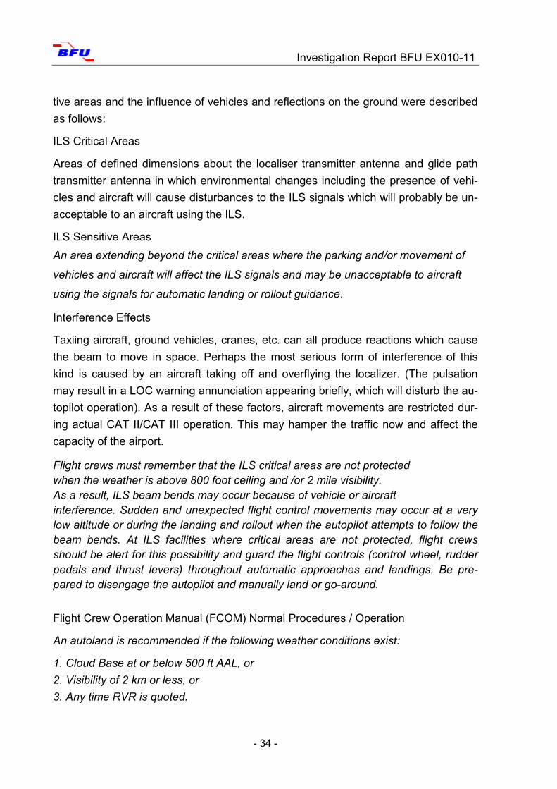
The Flight Crew Training Manual (FTCM) of the operator indicated the possibility of
interferences of the ILS localizer and glide slope if automatic approaches and land-
ings under CAT I conditions are conducted. Special ILS critical areas and ILS sensi-
Investigation Report BFU EX010-11
- 34 -
tive areas and the influence of vehicles and reflections on the ground were described
as follows:
ILS Critical Areas
Areas of defined dimensions about the localiser transmitter antenna and glide path
transmitter antenna in which environmental changes including the presence of vehi-
cles and aircraft will cause disturbances to the ILS signals which will probably be un-
acceptable to an aircraft using the ILS.
ILS Sensitive Areas
An area extending beyond the critical areas where the parking and/or movement of
vehicles and aircraft will affect the ILS signals and may be unacceptable to aircraft
using the signals for automatic landing or rollout guidance.
Interference Effects
Taxiing aircraft, ground vehicles, cranes, etc. can all produce reactions which cause
the beam to move in space. Perhaps the most serious form of interference of this
kind is caused by an aircraft taking off and overflying the localizer. (The pulsation
may result in a LOC warning annunciation appearing briefly, which will disturb the au-
topilot operation). As a result of these factors, aircraft movements are restricted dur-
ing actual CAT II/CAT III operation. This may hamper the traffic now and affect the
capacity of the airport.
Flight crews must remember that the ILS critical areas are not protected when the weather is above 800 foot ceiling and /or 2 mile visibility. As a result, ILS beam bends may occur because of vehicle or aircraft interference. Sudden and unexpected flight control movements may occur at a very low altitude or during the landing and rollout when the autopilot attempts to follow the beam bends. At ILS facilities where critical areas are not protected, flight crews should be alert for this possibility and guard the flight controls (control wheel, rudder pedals and thrust levers) throughout automatic approaches and landings. Be pre-pared to disengage the autopilot and manually land or go-around. Flight Crew Operation Manual (FCOM) Normal Procedures / Operation
An autoland is recommended if the following weather conditions exist:
1. Cloud Base at or below 500 ft AAL, or
2. Visibility of 2 km or less, or
3. Any time RVR is quoted.
Investigation Report BFU EX010-11
- 35 -
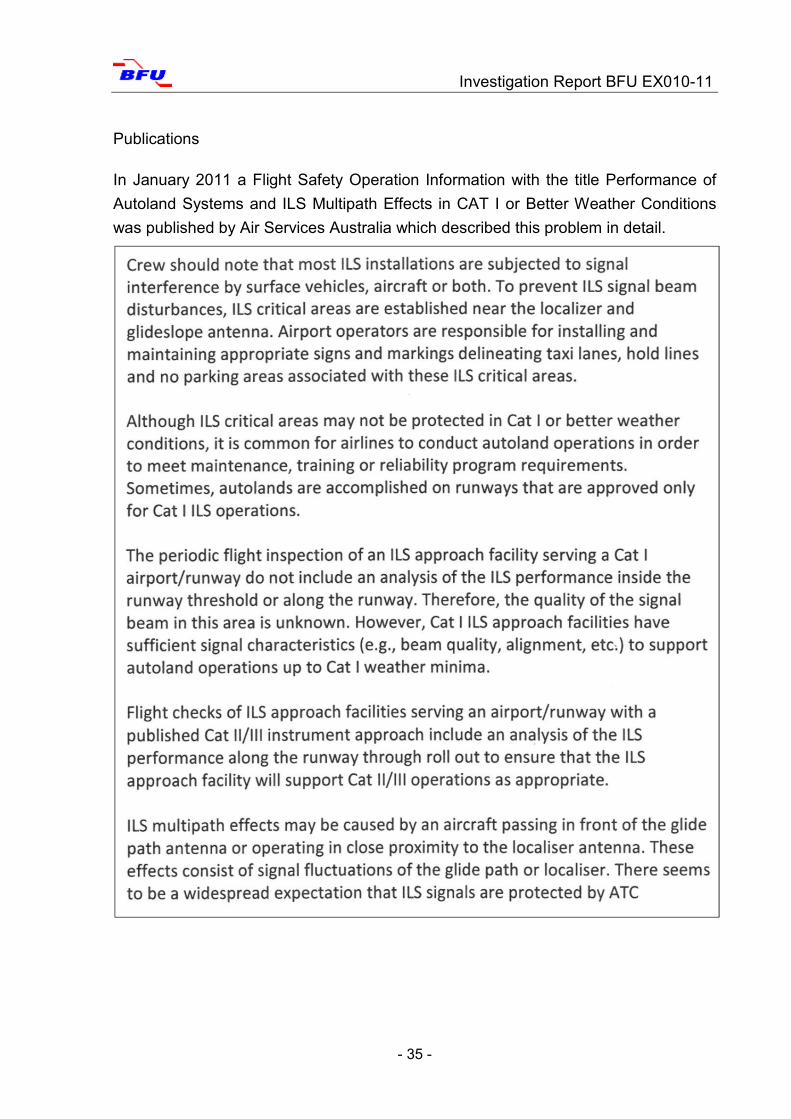
Publications
In January 2011 a Flight Safety Operation Information with the title Performance of
Autoland Systems and ILS Multipath Effects in CAT I or Better Weather Conditions
was published by Air Services Australia which described this problem in detail.
Investigation Report BFU EX010-11
- 36 -
The summary indicated that interferences of the localizer and/or the glide slope can
occur during automatic approaches under CAT I conditions. The crew has to be pre-
pared to immediately disconnect the autopilot and take over manual control.
This article was published within the operator to call the pilots' attention to the danger
of interference of ILS due to external influences during automatic approaches under
CAT I conditions.
The flight crew operations manual and the training manual stipulate the following:
B 777 Flight Crew Operations Manual
NORMAL PROCEDURES
Operation
Investigation Report BFU EX010-11
- 37 -
Note: When low visibility procedures are not in effect, the ILS critical areas are not
protected and ILS signal interference may occur. Pilots must, therefore, guard the
controls throughout the approach and landing.
SQ.NP.3.56, 15 Mar 2011
B 777 Flight Crew Training Manual
Flight crews must remember that the ILS critical areas are not protected when the
weather is above 800 foot ceiling and /or 2 mile visibility. As a result, ILS beam bends
may occur because of vehicle or aircraft interference. Sudden and unexpected �ight
control movements may occur at a very low altitude or during the landing and rollout
when the autopilot attempts to follow the beam bends. At ILS facilities where critical
areas are not protected, �ight crews should be alert for this possibility and guard the
�ight controls (control wheel, rudder pedals and thrust levers) throughout automatic
approaches and landings. Be prepared to disengage the autopilot and manually land
or go-around.
The Autopilot Flight Director System (AFDS) includes a monitor to detect signi�cant
ILS signal interference. If localizer or glideslope signal interference is detected by the
monitor, the autopilot disregards erroneous ILS signals and remains engaged in an
attitude stabilizing mode based on inertial data. Most ILS signal interferences last on-
ly a short period of time, in which case there is no annunciation to the �ight crew
other than erratic movement of the ILS raw data during the time the interference is
present.
No immediate crew action is required unless erratic or inappropriate autopilot activity
is observed.
1.17.3 Procedures of the Aircraft Manufacturer
The aircraft manufacturer Boeing writes the following regarding a go-around proce-
dures after touch-down:
If a go-around is initiated after touchdown but before thrust reverser selection, auto
speedbrakes retract and autobrakes disarm as thrust levers are advanced. The F/D
go-around mode will not be available until go-around is selected after becoming air-
borne. Once reverse thrust is initiated following touchdown, a full stop landing must
be made.
Investigation Report BFU EX010-11
- 38 -
2. Analysis
2.1 Technical Aspects
After analysing and assessing the facts, the BFU came to the conclusion that the air-
plane veered off the runway because the localizer signals had been distorted by a
departing aircraft. All three receiver antennas of the airplane received identical sig-
nals from the localizer on the ground so that on board no malfunction was indicated.
Because there was only a short interference of the localizer signal neither the near
field nor the far field monitor - which monitor the proper function of the ILS - regis-
tered a malfunction of the ILS. This means, the airplane followed the localizer signal.
The crew only realised about 30 ft above the runway that something was not correct
as the airplane slightly banked to the left and then drifted left. The left main landing
gear touched down directly afterwards which resulted in the disengagement of the
go-around mode. This prevented the crew from being able to initiate an automatic go-
around.
2.2 Crew Behaviour
The preparation and conduct of the approach and the intended automatic landing
were in accordance with the valid flight operations procedures of the operator. The
fact that both pilots had arrived from Singapore two days prior to this flight suggests
that, at the time of the occurrence, they did not experience an increase in psycholog-
ical stress due to jet lag. The flight occurred at a favourable time for the crew - in
Singapore it would have been afternoon - and therefore fatigue is not really feasible.
The crew did not inform the approach controller of their intention to conduct an auto-
matic landing.
The crew knew that under the prevailing CAT I flight operations the safety measures
of all-weather operations CAT II/III were not present.
Therefore, the crew had to take into consideration that ILS interferences due to other
airplanes on the ground or in the air were possible.
Based on the crew statements the BFU is of the opinion that the crew was prepared
to initiate a go-around procedure in case of an incident. The PIC stated that as the
airplane dipped the left wing shortly before touch-down he wanted to initiate a go-
around and pushed the TO/GA button. Even though the PIC’s command “Okay, flaps
Investigation Report BFU EX010-11
- 39 -
twenty.” did not completely meet the requirements of the standard phraseology for a
go-around “Go-Around Flaps 20” it was his command to go-around. The analysis of
the FDR showed that the co-pilot did not set the flaps to 20°. The crew stated that in
their estimate a go-around procedure initiated manually with an airplane already on
the ground would have been much more dangerous than remaining on the ground.
The FDR analysis in combination with the sonogram indicates that the TO/GA button
was pushed simultaneously with the initial ground contact of the left main landing
gear. The crew anticipated that the Go-Around Mode would initiate a go-around, but
nothing happened. The Go-Around Mode had deactivated as designed by Boeing
(system logic) by the initial ground contact of the main landing gear.
The PIC realised that the ground spoilers had already been deployed automatically
and retracted them manually. This would not have been necessary. Had he pushed
the thrust levers forward the ground spoilers would have been retracted automatically
and the autobrake function deactivated.
The BFU is of the opinion that both pilots, the PIC due to him being an instructor pilot
and the co-pilot having enough flying experience on type, were sufficiently familiar
with the go-around procedure. These procedures were sufficiently described in the
FCTM and had been trained sufficiently in the simulator in accordance with effective
regulations.
2.3 Relocation of the Instrument Landing System At Munich Airport the localizer antennas were moved from 350 m to 1,000 m beyond
the runway threshold. The air traffic service provider stated that it had become nec-
essary because of the Airbus A380 operation to prevent localizer interferences
through reflections off airplanes.
The BFU is of the opinion that the position change of the LOC antenna effected the
separation of approaching and departing aircraft. In order to prevent interferences
with the LOC antenna separation inevitably would have to be increased. Further-
more, the broadcast antenna diagram has to be pooled better by about 3.6° to en-
sure the required accuracy for CAT II and CAT III approaches which results in an in-
crease in energy supply by approximately 0.1 W.
Investigation Report BFU EX010-11
- 40 -
2.4 Behaviour of the Air Traffic Controllers The controller stated that he had been under a high workload, because of all-weather
operations in the morning (CAT II/III), delays had occurred which, at the time of the
occurrence, resulted in an increased departure rate in combination with approaches
on runway 08R. This forced the controller to work on the edge of the separation min-
imum so that aircraft waiting to depart could do so quickly and traffic situation would
become normal. Since the controller did not have any information that the crew in-
tended to conduct an automatic landing he did not separate the aircraft in accord-
ance with the required separation minima for CAT II/III but for CAT I conditions; i.e.
separation between departing and approaching aircraft was one runway length. The
air navigation service provider stated that if the controller had been informed he
would not have allowed the BAE 146-RJ85, waiting on taxiway B4, to take off ahead
of the B 777.
At the time of the occurrence the provision phase for CAT II/III was still active even
though the weather situation would have allowed for the cancellation of all-weather
operations CAT II/III in accordance with the Manual of Operations Air Traffic Services
(MO-ATS). Air traffic had already begun to separate the aircraft in accordance with
CAT I. Provided the crew had informed the controller about the planned autoland the
option would have existed to return to CAT III operations. This would have been pos-
sible with relatively little effort because the protection zones were still free since the
change from CAT II/III to CAT I conditions and the waiting departing aircraft still
stopped at the CAT II/III holding point.
2.5 Accident Site
Because the shoulders of the runway had been paved with macadam and it had not
rained in quite some time, the wheels of the airplane did not sink in too much and the
landing gear was not damaged.
2.6 Automatic Landing
The investigation determined that autoland landings under CAT I conditions are con-
ducted without informing air traffic control. If an international regulation for such cas-

Investigation Report BFU EX010-11
- 41 -
es existed that air traffic control had to be informed about an intended autoland the
controllers would have been better prepared and might have made appropriate prep-
arations.
If the airport does not operate on LVP, it should become global standard to inform air
traffic control on time about an intended autoland landing.
Investigation Report BFU EX010-11
- 42 -
3. Conclusions
3.1 Findings Both pilots held the required licenses and ratings for the conduct of the flight.
The airplane was properly certificated and maintained in accordance with exist-ing regulations and approved procedures.
At the time of the occurrence the airplane was in proper technical condition.
Two days prior to the flight the crew had arrived from Singapore. Considering the time lag of six hours the flight took place during the day (according to their circadian rhythm) and therefore fatigue was not a factor.
At a visibility of 2 km and a cloud base of 300 ft CAT I was in operation.
Due to the CAT II/III provision phase the protection zones of the ILS 08R were ensured but the separation criteria for CAT II/III were no longer in use.
The separation of the airplanes corresponded with CAT I.
The crew did not inform the controller of the intended autoland landing.
The decision to conduct an automatic landing under the prevailing weather con-ditions was understandable.
The position of the localizer antenna for landing direction 08R was moved from 350 m beyond the runway threshold 26L to 1,000 m.
To avoid interferences the relocation of the localizer antenna requires a larger separation of airplanes when all-weather operation CAT II/III is in service.
The larger distance of the localizer antenna to the runway requires a stronger pooling (about 0.36°) of the signal which results in an increased energy supply (about 0.1 W) which increases the susceptibility to dysfunction slightly. These effects were taken into account and the respective protection areas extended.
A BAE 146-RJ85 taxied along taxiway B4 to runway 08R as the B 777 was about 2.9 NM ahead of the runway threshold 08R and 3.4 NM behind the BAE 146-RJ85 when it received take-off clearance.
As the B 777 flew above the runway threshold 08R, the BAE 146-RJ85 was in front of the localizer antenna and interfered with the localizer signal.
The BAE 146-RJ85 was significantly lower in front of the localizer antenna compared to other airplanes having taken off earlier due to it taken off from the taxiway B4 intersection and its lower climb rate. This resulted in a significantly greater localizer interference.
The B 777 followed the disturbed localizer signal with engaged autopilot.
The crew realised the interference too late and was confused by the deviation of the airplane to the left.
Investigation Report BFU EX010-11
- 43 -
Neither the near nor the far field monitor recorded a dysfunction of the ILS due to the shortness of the interference.
The intention of the PIC to conduct a missed approach procedure with engaged autopilot failed because the go-around mode had been deactivated by the initial ground contact.
The airplane touched down with a bank angle of 3.5° to the left and about 7 seconds later veered off the runway to the left.
The autopilot was not disconnected in time because the PIC had been prepared for an automatic go-around. The PIC decided against a manual go-around pro-cedure due to safety reasons because the airplane had switched to ground mode.
Due to the sudden disconnection of the autopilot and the rudder full deflection induced by the pilots, the airplane turned back around the yaw axis by about 40° to the right.
The airplane crossed the runway in about 45° to the approach direction and came to rest at the right side of the runway in the direction of the flight.
Because of the gravel runway shoulder area and the long dry weather the air-plane did not sink in very far and remained almost undamaged.
The passengers and the crew could leave the airplane without injuries via at-tached stairways.
Investigation Report BFU EX010-11
- 44 -
3.2 Causes
The Serious Incident was caused by the following:
Immediate Causes:
The crew decided to conduct an automatic landing even though the conditions
on the ground for a safe conduct were not given.
Shortly before touch-down the airplane was deviated to the left of its flight di-
rection by the disturbed LOC signal. A BAE 146-RJ85 taking off a short dis-
tance ahead of the B 777 caused the interference.
The two pilots could not keep the airplane on the runway after touch-down be-
cause the autopilot was still engaged.
The crew was confused by the behaviour of the airplane. They had not noticed
that the go-around mode had already been deactivated by the initial touch-
down of the left main landing gear.
Systemic Causes:
The recommendation concerning the conduct of autoland landings under
CAT I conditions published in the FCOM of the operator allowed the decision
for an autoland landing without having to consider the required conditions on
the ground.
4. Safety Recommendations
Actions by the Operator
After the occurrence the operator implemented the following safety actions:
Additional guidelines for flight crews for the successful conduct of go-around proce-
dures after touch-down.
Improved simulator training for flight crews during recurring and re-training to train
go-around procedures after the aicraft has switched to ground mode.
Improved simulator training for flight crews to train LOC deviations during flare mode
below 50 ft.

Investigation Report BFU EX010-11
- 45 -
Investigator in charge: L. Müller
Assistance: Himmler
Ritschel
Blanke
Report finalisation: Friedemann
5. Appendix
Investigation Report BFU EX010-11
- 46 -
Appendix 1
Investigation Report BFU EX010-11
- 47 -
Appendix 2
Flight data recorder print-out