Embed Size (px)
Citation preview
Finite Elements in Analysis and Design 9 (1991) 23-32 23 Elsevier
Exact stiffness matrix for twisted helix beam
A.Y.T. Leung
Department of Civil and Structural Engineering, University of Hong Kong, Pokfulam Road, Hong Kong
Received January 1990 Revised September 1990
Abstract. Natural shape functions are derived for curved and twisted beam finite elements including shear deformation. Natural shape functions are exact solutions of the governing equations subject to boundary forces only. Rigid-body modes are completely satisfied and all complications associated with curved finite elements by assumed shaped functions, parametric transformation, and numerical integration are eliminated. The formula- tion of the stiffness matrix is given in detail.
Introduction
To develop a good stiffness matrix for a spatially curved and twisted beam finite element requires many special techniques [1-4]. Natura l shape functions, satisfying the requirements of r igid-body modes and constant strain (and curvature change), were developed recently for twisted [8] and for untwisted [9] spatially curved helix elements.
It is the purpose of this paper to derive the natural shape functions for uniformly twisted helix elements without approximations except those using the governing equations. For a brief review of the historical development of the governing equations, the reader is referred to Ref.
[81. Mottershead [10] also used exact shape functions, employing an energy approach. The
stiffness matrix is obtained by integrating the matrix produc t of shape funct ion differentials. N o explicit forms were given. The explicit stiffness matrix is derived here by means of the transfer matrix [11].
Governing equations
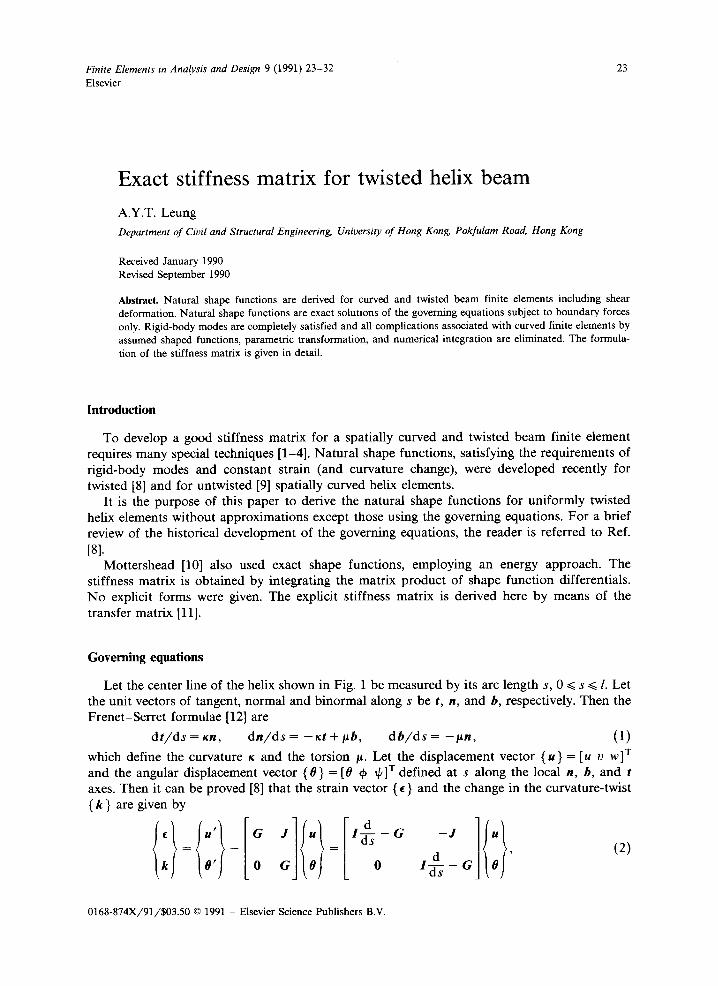
Let the center line of the helix shown in Fig. 1 be measured by its arc length s, 0 ~< s ~< l. Let the unit vectors of tangent, normal and binormal along s be t, n, and b, respectively. Then the Frene t -Ser re t formulae [12] are
d t / d s = Kn, d n / d s = - x t + # b , d b / d s = - gn , (1)
which define the curvature x and the torsion g. Let the displacement vector ( u ) = [u v w]T and the angular displacement vector ( 0 ) = [0 q, tp] T defined at s along the local n, b, and t axes. Then it can be proved [8] that the strain vector ( c ) and the change in the curvature-twist { k } are given by
i d _ (2) 0' 0 G 0 0 ds G 0
0168-874X/91/$03.50 © 1991 - Elsevier Science Publishers B.V.
24 A.Y.T. Leung / Stiffness matrix for twisted helix beam
/ \
' " - ~ / 7
I i , I
I IB
~:+1 2 o " , j / (2
:Helix ~ I centre-I in ~.
I
f I / i "" ""
r + X
x /
V Ov
I Sv
/, ~u~. ¢x ~ , .
M w
Fig. 1. Definition of displacements, rota- tion, forces and moments.
where pr imes denote derivatives with respect to s, the skew-symmetr ic matr ices are given by [0+ [010] [ G ] = -~" 0 # and [ J ] = - 1 0 0 , (3)
x - t~ 0 0 0 0
[ I ] is the identi ty matrix, and ~" is the twist of the pr incipal axes. The local shear {V} = [ V x Vy Vz] T and m o m e n t { M } = [ M x My Mz] v
and { k } by the consti tutive equation, are related to { ~ }
I:l=[ +u +u O,das'+]In} ' (4)
where [E,] = diag[GA x, GAy, EAz] and [Eo} = diag[EI x, Ely, EIz], in which A x and /ly are the effective shear areas, A z the cross-sectional area of the beam, I x and Iy the second moments of area about the x and y-axes respectively, 1 z the torsional constants , and E and G denote Young ' s modulus and the shear modulus respectively. The rigidity matr ices [E,] and leo] may be fully popula ted if the axes are not pr incipal and are not a long the shear center.
Since the equil ibrium of { V } and { M } is conjugated to the compat ib i l i ty of { ¢ } and { x } [13], the equil ibrium equation, in the absence of internal forces, is given by
I °lI ll:l t & - ~ = {o}, J ds G E o 0 I - G
(5)
A. Y. 72 Leung / Stiffness matrix for twisted helix beam 25
o r
,d ds - G 0 V
1d____ - J ds G M
{0}. (6)
Equation (5) defines a self-adjoint system. To solve the governing eqn. (5) for the twelve sets of boundary conditions at which each of
the six components of (/~(s)}, {0(s)} at each of the two end nodes, s = sl, s2, attains a unit value while all the others are zero is our primary aim for the natural shape functions. The construction of the stiffness matrix is our second goal.
Solution of the governing equations
Before solving eqn. (5), we consider the solution of a set of linear ordinary differential equations of the following form:
{ x ' ( s ) } = [ r ] { x ( s ) } + { / ( s ) } , (7)
where IF] is a given constant matrix, { f(s)} a given force vector dependent on s, and {x(s)} is the unknown vector to be determined. The solution of eqn. (7) is given by [14]
{x(s )} = [ e " l { A } + [ e " l f [ e - ' S ] { / ( s ) } ds, (8)
where { A } is a constant vector to be determined by the boundary conditions. Now, eqn. (5) is written in factorized form and can be solved in two stages: (i) eqn. (6) for
equilibrium, and (ii) eqn. (4) for the displacements. Solving the first equation of (6) for { V }, one has
{ V(s)) = [eaS]{A1}, (9)
where {A1} is a vector with three constants of integration which are determined by the boundary conditions; the evaluation of the matrix [e as] will be discussed in the next section. Solving the second equation of (6), where the force vector is given by
{ f ( s ) } = [J]{V(s)} = [J l [eaS] {A , } , (10)
one has
{ M (s )} = [ea ' ]{A2} + [L0(s)] {A1}, (11)
where { A 2 } is again a vector of integration constants and
[L0(s)] = [ e a ' l f [ e asl[Jl[ea '~] ds (12)
will be evaluated later. Similarly, one can solve the second row of equation (4) for { 0 } and then the first for { u } to give,
= + [ t , ( s ) ] + [ t : ( s ) ] { A , ) , (13)
and
{ I / ( S ) } = [eGS](A4} Jr-[L3(s)]{A3} + [L4(s ) ] {A2} q- [L5 (s ) ] {A I } , (14)
26
where
A. Y. T. Leung / Stiffness matrix for twisted helix beam
[Ll(S)]
[t:(s)]
[L4(s)]
Its(s)]
=[eas]f[e-aS][Eel][eaS]ds,
=[eas]f[e-aS][Egl][Lo(s)] ds,
= [eas]f [e-a*][ J][e as] d s = [L0(s)] ,
= [ e a s ] f [ e - a q [ J ] [ t , ( s ) ] ds,
= [eas]f [e a s ] [ J L 2 ( s ) + E u l e as] ds
will be evaluated using the Cay ley -Hami l ton theorem in the next sections, and { A i} , i = 1, 2, 3, 4, are vectors of integration constants that are determined by the appropr ia te boundary conditions.
Evaluation of le as ]
The Cay ley -Hami l ton theorem [15] states that a matr ix satisfies its own characteristic equation. Therefore, one can express a matr ix in power series form as
[e as] = ~ [G]Js ' / j ! (15) j=0
by powers not exceeding [G] 2, since [G] is of order three. That is,
[e as] = a2[G]2s 2 + a,[G]s + a 0 [ I ] , (16)
where the constants a i satisfy
e ~'s = ~2)k2r $2 -1- OllXrS + OgO, (17)
in which ~r is an eigenvalue of [G]. Now, the eigenvalues of [G] are
2~1 = O, )% = ias, ~3 = - i a s , (18)
where a 2 = r 2 + x2+ / ,2 and i = f Z 1 . Substituting eqns. (18) into (17) gives three equations for the determinat ion of ai, i = 0, 1, 2, namely
a0 = 1, a 1 = (sin as) /as , a2 = (1 - cos as)/a2s 2, (19)
and the matrix exponent is obtained from eqn. (16). The integrations for [L~(s)] are algebrai- cally involved. The results are listed in the Appendix for reference.
Boundary conditions
One can combine eqns. (13) and (14) into the following form:
0(S) LL2(s) t i c s ) e as 0 A3 ~A4
(2o)
A. Y. T. Leung / Stiffness matrix for twisted helix beam 27
The vector of integration constants { A } is determined by the boundary conditions at s = 0 and l,
{q} ~ u ( l ) [ [L( I ) {A} = [ R ] - I ( A } or {A} = [ R ] { q } , (21)
[o ( t ) )
Therefore, one can express the displacement functions in terms of the nodal displacement vector (q } by means of the natural shape functions [N(s)],
.<s)) = = [N(s)] {q}. (22) O(s)
Stiffness matrix
The stiffness matrix is usually obtained by consideration of the strain energy. A simple alternative not using integration has been adopted here, because eqns. (9) and (11) give the
Forces
kN Moments
0.5 1.0 1.5 2.0 rad
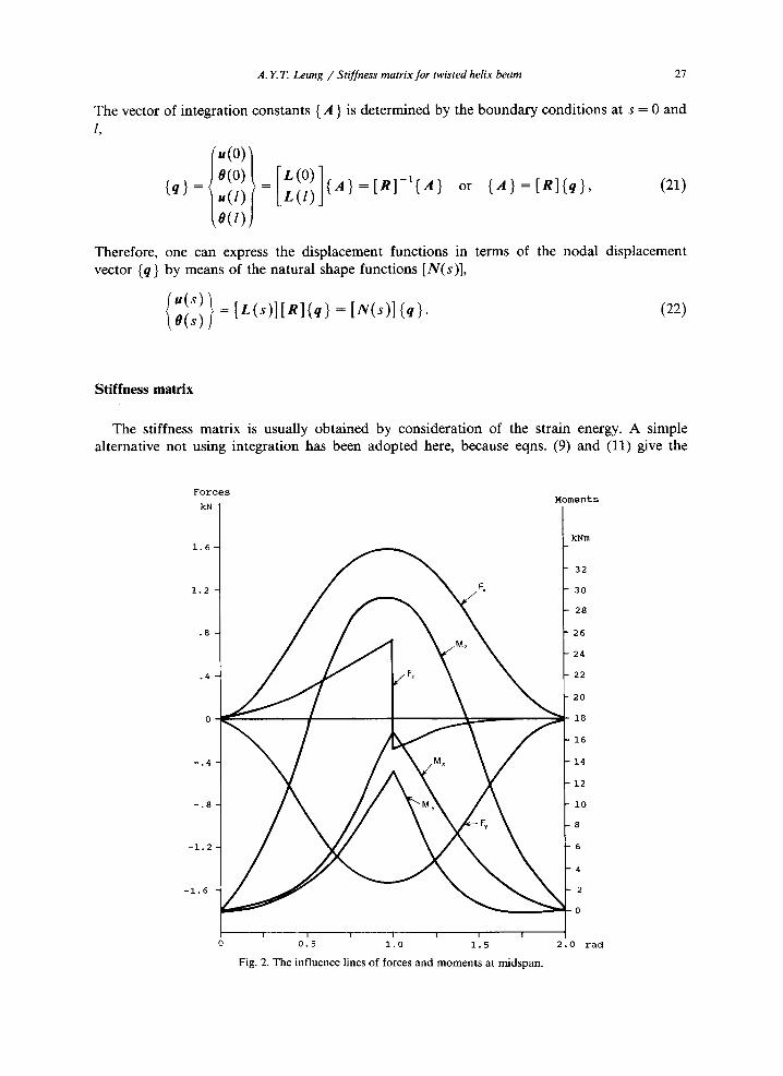
Fig. 2. The influence lines of forces and moments at midspan.
1.6 I kNm
32
1.2 30
28
.8 26
24
.4 22
20
18
16
-.4 14
12
-.8 i0
8
-1.2 6
4
-1.6 2
0
28 A. Y. T. Leung / Stiffness matrix for twisted helix beam
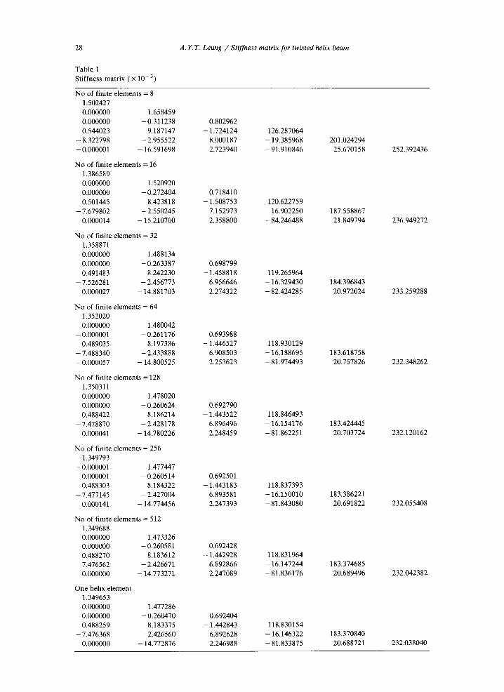
T a b l e 1
S t i f f n e s s m a t r i x ( x 10 - 3 )
N o o f f in i t e e l e m e n t s = 8
1 . 5 0 2 4 2 7
0 . 0 0 0 0 0 0 1 . 6 5 8 4 5 9
0 . 0 0 0 0 0 0 - 0 . 3 1 1 2 3 8
0 . 5 4 4 0 2 3 9 . 1 8 7 1 4 7
- 8 . 3 2 2 7 9 8 - 2 . 9 5 5 5 2 2
- 0 . 0 0 0 0 0 1 - 1 6 . 5 9 1 6 9 8
N o o f f in i t e e l e m e n t s = 16
1 . 3 8 6 5 8 9
0 . 0 0 0 0 0 0 1 . 5 2 0 9 2 0
0 . 0 0 0 0 0 0 - 0 . 2 7 2 4 0 4
0 . 5 0 1 4 4 5 8 . 4 2 3 8 1 8
- 7 . 6 7 9 8 0 2 - 2 . 5 5 0 2 4 5
0 . 0 0 0 0 1 4 - 1 5 . 2 1 0 7 0 0
N o o f f i n i t e e l e m e n t s = 32
1 . 3 5 8 8 7 1
0 . 0 0 0 0 0 0 1 . 4 8 8 1 3 4
0 . 0 0 0 0 0 0 - 0 . 2 6 3 3 8 7
0 . 4 9 1 4 8 3 8 . 2 4 2 2 3 0
- 7 . 5 2 6 2 8 1 - 2 . 4 5 6 7 7 3
0 . 0 0 0 0 2 7 - 1 4 . 8 8 1 7 0 3
N o o f f i n i t e e l e m e n t s = 6 4
1 . 3 5 2 0 2 0
0 . 0 0 0 0 0 0 1 . 4 8 0 0 4 2
- 0 . 0 0 0 0 0 1 - 0 . 2 6 1 1 7 6
0 . 4 8 9 0 3 5 8 . 1 9 7 3 8 6
- 7 . 4 8 8 3 4 0 - 2 . 4 3 3 8 8 8
- 0 . 0 0 0 0 5 7 - 1 4 . 8 0 0 5 2 5
N o o f f in i t e e l e m e n t s = 128
1 . 3 5 0 3 1 1
0 . 0 0 0 0 0 0 1 . 4 7 8 0 2 0
0 . 0 0 0 0 0 0 - 0 . 2 6 0 6 2 4
0 . 4 8 8 4 2 2 8 . 1 8 6 2 1 4
- 7 . 4 7 8 8 7 0 - 2 . 4 2 8 1 7 8
0 . 0 0 0 0 4 1 - 1 4 . 7 8 0 2 2 6
N o o f f in i t e e l e m e n t s = 256
1 . 3 4 9 7 9 3
- 0 . 0 0 0 0 0 1 1 . 4 7 7 4 4 7
0 . 0 0 0 0 0 1 - 0 . 2 6 0 5 1 4
0 . 4 8 8 3 0 3 8 . 1 8 4 3 2 2
- 7 . 4 7 7 1 4 5 - 2 . 4 2 7 0 0 4
0 . 0 0 0 1 4 1 - 1 4 . 7 7 4 4 5 6
N o o f f in i t e e l e m e n t s = 512
0 . 8 0 2 9 6 2
- 1 . 7 2 4 1 2 4 1 2 6 . 2 8 7 0 6 4
8 . 0 0 0 1 8 7 - 1 9 . 3 8 5 9 6 8 2 0 1 . 0 2 4 2 9 4
2 . 7 2 3 9 4 0 - 9 1 . 9 1 0 8 4 6 2 5 . 6 7 0 1 5 8
0 . 7 1 8 4 1 0
- 1 . 5 0 8 7 5 3 1 2 0 . 6 2 2 7 5 9
7 . 1 5 2 9 7 3 - 1 6 . 9 0 2 2 5 0 1 8 7 . 5 5 8 8 6 7
2 . 3 5 8 8 0 0 - 8 4 . 2 4 6 4 8 8 2 1 . 8 4 9 7 9 4
0 . 6 9 8 7 9 9
- 1 . 4 5 8 8 1 8 1 1 9 . 2 6 5 9 6 4
6 . 9 5 6 6 4 6 - 1 6 . 3 2 9 4 3 0 1 8 4 . 3 9 6 8 4 3
2 . 2 7 4 3 2 2 - 8 2 . 4 2 4 2 8 5 2 0 . 9 7 2 0 2 4
0 . 6 9 3 9 8 8
- 1 . 4 4 6 5 2 7 1 1 8 . 9 3 0 1 2 9
6 . 9 0 8 5 0 3 - 1 6 . 1 8 8 6 9 5 1 8 3 . 6 1 8 7 5 8
2 . 2 5 3 6 2 3 - 8 1 . 9 7 4 4 9 3 2 0 . 7 5 7 8 2 6
0 . 6 9 2 7 9 0
- 1 . 4 4 3 5 2 2 1 1 8 . 8 4 6 4 9 3
6 . 8 9 6 4 9 6 - 1 6 . 1 5 4 1 7 6 1 8 3 . 4 2 4 4 4 5
2 . 2 4 8 4 5 9 - 8 1 . 8 6 2 2 5 1 2 0 . 7 0 3 7 2 4
0 . 6 9 2 5 0 1
- 1 . 4 4 3 1 8 3 1 1 8 . 8 3 7 3 9 3
6 . 8 9 3 5 8 1 - 1 6 . 1 5 0 0 1 0 1 8 3 . 3 8 6 2 2 1
2 . 2 4 7 3 9 3 - 8 1 . 8 4 3 0 8 0 2 0 . 6 9 1 8 2 2
1 . 3 4 9 6 8 8
0 . 0 0 0 0 0 0 1 . 4 7 3 3 2 6
0 . 0 0 0 0 0 0 - 0 . 2 6 0 5 8 1 0 . 6 9 2 4 2 8
0 . 4 8 8 2 7 0 8 . 1 8 3 6 1 2 - 1 . 4 4 2 9 2 8 1 1 8 . 8 3 1 9 6 4
- 7 . 4 7 6 5 6 2 - 2 . 4 2 6 6 7 1 6 . 8 9 2 8 6 6 - 1 6 . 1 4 7 2 4 4 1 8 3 . 3 7 4 6 8 5
0 . 0 0 0 0 0 0 - 1 4 . 7 7 3 2 7 1 2 . 2 4 7 0 8 9 - 8 1 . 8 3 6 1 7 6 2 0 . 6 8 9 4 9 6
O n e he l ix e l e m e n t
1 . 3 4 9 6 5 3
0 . 0 0 0 0 0 0 1 . 4 7 7 2 8 6
0 . 0 0 0 0 0 0 - 0 . 2 6 0 4 7 0 0 . 6 9 2 4 0 4
0 . 4 8 8 2 5 9 8 . 1 8 3 3 7 5 - 1 . 4 4 2 8 4 3 1 1 8 . 8 3 0 1 5 4
- 7 . 4 7 6 3 6 8 - 2 . 4 2 6 5 6 0 6 . 8 9 2 6 2 8 - 1 6 . 1 4 6 3 2 2 1 8 3 . 3 7 0 8 4 0
0 . 0 0 0 0 0 0 - 1 4 . 7 7 2 8 7 6 2 . 2 4 6 9 8 8 - 8 1 . 8 3 3 8 7 5 2 0 . 6 8 8 7 2 1
2 5 2 . 3 9 2 4 3 6
2 3 6 . 9 4 9 2 7 2
2 3 3 . 2 5 9 2 8 8
2 3 2 . 3 4 8 2 6 2
2 3 2 . 1 2 0 1 6 2
2 3 2 . 0 5 5 4 0 8
2 3 2 . 0 4 2 3 8 2
2 3 2 . 0 3 8 0 4 0
A. Y.T. Leung / Stiffness matrix for twisted helix beam 29
exact internal resistance already,
(v s, 01<A1 ) ,23, M ( s ) } = LLo(s) e ~s A2 "
The components of (V(s)} and (M(s)) are physical quantities having physical dimensions. When they are arranged in an order corresponding to those of (q } at the two nodes,
- v ( o ) ] -M(0)~=
o= v(t) [ M(I) )
- I 0 0
-to(O) - I o e ~l 0 0
Lo(I ) e ~l 0
A2
A3
A 4
= [ S ] ( A ) = [ S ] [ R ] ( q ) = [ K ] ( q } , (24)
where [S] is the square matrix, [R] is given by eqn. (21) and
[x]=[s ] [R] (25)
is the exact stiffness matrix.
Forces
kN
1,6
1.2
.8
.4
Mz
Moments
kNm
80
60
40
2 0
- . 4 - M×
-20
- . 8
- 1 . 2
- 1 . 6
F v ~- -40
-60
v I -80
I I I I ] I I 0.5 1.0 1.5 2.0 rad
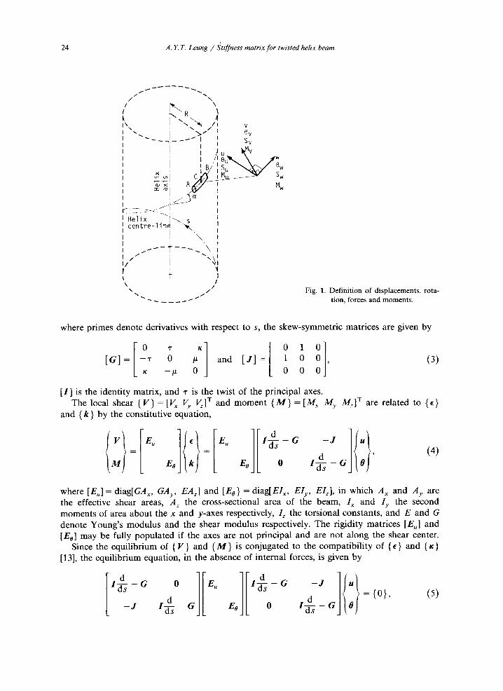
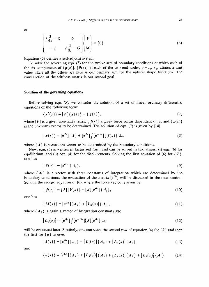
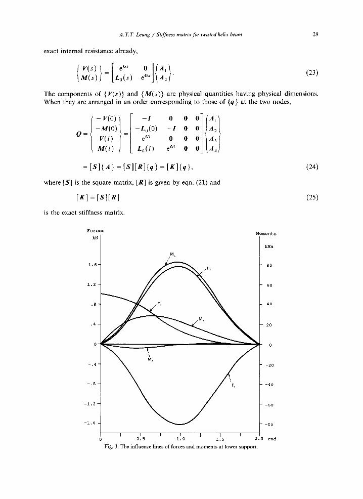
Fig. 3. The influence lines of forces and moments at lower support.
30 A.Y.T. Leung / Stiffness matrix for twisted helix beam
Numerical examples
Consider a circularly cylindrical helix of centroidal radius R = 10 and cross-sect ional radius r = 0.1. The other properties are ~ = 10 °, Young's modulus E = 69 × 10 9, shear modulus G = 26 × 10 9, shear factor 1.2. The lower end is fixed and the height is 2,~R tan 10 ° = 11.079. The stiffness matrix is checked by straight finite e lement segments using 8, 16, 32, 64, 128, 256, and 512 e lements and the results are tabulated in Table 1. It is found that one helix e lement is as good as 512 conventional finite e lements .
The calculation of the influence lines of a helically elevated ( c l a m p e d - c l a m p e d ) bridge by two helix e lements is taken as a second example. The physical properties of the rectangular cross-section are b = 8, d = 1.5, E = 30 × 10 9, G = 12.5 x 10 9, J = 7.937, R = 100, and the height is 2 R tan 1.432 ° = 5. For a downward concentrated force P = 1, the influence lines of the reactions at the midspan and at the lower end are plotted in Figs. 2 and 3 respectively.
References
[1] D.G. ASHWELL and R.H. GALLAGHER (eds.), Finite Elements for Thin Shells and Curved Members, Wiley, London, 1976.
[2] O.C. ZIENKIEWICZ, The Finite Element Method, McGraw-Hill, London, 1977. [3] H. KARDESTUNCER (ed.), Finite Element Handbook, McGraw-Hill, New York, 1987. [4] R.D. COOK, Concepts and Applications of Finite Element Analysis, Wiley, New York, 1981. [5] J.S. PREMIENIECKI, Theory of Matrix Structural Analysis, McGraw-Hill, New York, 1968. [6] J.R. BANERJEE and F.W. WILLIAMS, "Exact Bernoulli-Euler dynamic stiffness matrix for a range of taper beams",
Int. ~L Num. Methods Eng. 21, pp. 2289-2302, 1985. [7] J. HENRYCH, The Dynamics of Arches and Frames, Elsevier, Amsterdam, 1981. [8] B. TABARROK, A.N. SINCLAIR, M. FARSHAD and H. YI, "On the dynamics of spatially curved and twisted rods--A
finite element formulation", J. Sound Vib. 123, pp. 315-326, 1988. [9] M.R. BANAN, G. KARAMI and M. FARSHAD, "Finite element analysis of curved beams on elastic foundations",
Comput. Struct. 32, pp. 45-53, 1989. [10] J.E. MOTTERSHEAD, "Finite elements for dynamical analysis of helical rods", Int. J. Mech. Sci. 22, pp. 267-283,
1980. [11] D. PEARSON, "The transfer matrix method for the vibration of compressed helical springs", Int. J. Mech. Sci. 24,
pp. 163-171, 1982. [12] K.L. WARDLE, Differential Geometry, Routledge and Kegan Paul, London, 1965. [13] W.H. WITTRICK, "On elastic wave propagation in helical springs", Int. J. Mech. Sci. 8, pp. 25-47, 1966. [14] R. BRONSON, Differential Equations, McGraw-Hill, New York, 1973. [15] L.A. PIPES, Matrix Methods for Engineers, Prentice Hall, Englewood Cliffs, N J, 1973.
Appendix
Let
and
{ k } = [ ~ k "7"] T,
- /~k [ B ] = k T k j = - k 2
- k - r
l = E o 1 ,
/~2 0
~tk 0 /~- 0
I ix2,r ixk,r
[ C ] = k k T J G = - I.tk'r k2'r
p,,r 2 k r 2
Y = E ~ 1, 6 = a s ,
/zk 2 _ ~3 ]
k3 - # 2 k / '
k 2r -/.te'r J
A. Y.T. Leung / Stiffness matrix for twisted helix beam 31
then
a l 1 (~'s cos 3 ) G + 1 ( 1 rs sin 3 ) GG + C T, Lo(s ) = (sin 8 ) B - (cos 3 ) C + - ~ a3 ~-g
L~(s)=-~skkTZkkT +-~(sin S)kkTZGTG--~Z(cos S)kkXZG
1 _~ + ~ (8 cos 8 + sin 8 )G TGZG *G + GZkk T
1 (8 cos 8 - sin 8) GZG + 2 - ~ (8 sin 8 ) GZG TG 2a 3
1 + 2~--~(8 sin 3) GTGZG,
L2(s ) = - (cos 3)kkWZB- 4(Sina 3)kkTZC+ ~--g (cos 3 + 3 sin 3)kkTZG
+ -~-y (sin 3 -- 3 cos 3)kkTZGG + kkTZC w + (3 sin 3)GTGZB
1 (sin 3 + 3 cos 3)GTGZC 2a 7
+ -~a6 (cos 3 + 23 sin 3 + 282 cos 3)GTGZG
--T---r (sin 3 - 28 cos 3 + 232 sin 3)GXGZGG + 8 a 7
+ 2 - ~ ( s i n 3 - 3 c ° s 3 ) G Z B - 1 2a 6 (3 sin 3)GZC ,j-
+ 8a 5 ( - s i n 3 + 23 cos 3 + 232 sin 3)GZG
+ ~-ga6 (cos 3+23 sin 3 - 232 cos 3)GZGG+ GZC T,
L4 = 1_1 _ ( ~ 2 a 6 sin 3)BZGTG+ -~CZkk T - 2a 61 (3 sin 3 + 2 cos 3)CZG
1 1 + 2a 7 (sin 3 - 3 cos 3)CZGTG+ 2a 5 (sin 3 - 3 cos 3)BZG
lgBTZkkT_ 1 1 (3 cos 3 + sin 3)BTZG 2a 6 (8 sin 3)BTZGTG + 2a 5
q- ~ a 6 ( 3 2 COS 3 q- 3 sin 3 - c o s 3 ) G Z G T G
__r (3 sin 3 - 32 cos 3 - cos 3)GTGZG+ -~gCXZkk T 4a 6
1 + (sin 8 - 8 cos 8)C~ZG~G- 1 (8 sin a)C~ZG
2a 7 2a 6
rs (3 sin 3 - c o s 3)GTGZGTG+ rs (cos 3 + 3 sin 3)GZG 4a 6 4a 4
a 6 GZkkT,
32 A.Y.T. Leung / Stiffness matrix for twisted helix beam
Ls(s )= 1 . ( s i n ~ - S c o s S ) B Z B - 1 2a" 2a 8 (8 sin 8)BZC
i" (262 sin 8 + 28 cos 8 - sin 8)BZG + 8 a 7
~" (28 sin 8 - 282 cos 8 + cos 8)BZGG + 8a 8
1 (6 sin 8 + 2 cos 8)CZB- ~ a 9 (sin 8 - 8 cos 8)CZC 2a 8
r (68 sin 8 - 282 cos 8 + 7 cos 8)CZG + 8a 8
+ 8a9 ( - 282 sin S - 66 cos S + 7 sin S )CZGG + CZC "r
+ 21a 7 (8 cos 8 + sin 8)BTZB + 1---1-(8 sin 8)BTZC 2a 8
L (26 cos 8 + 262 sin 8 + 3 sin 8)BTZG 8 a 7
+ ~-aS (282 cos 8 - 2 8 s i n S + 3cosS )BTZGG-~BTZC "r
r (28 cos 8 + 282 sin 8 - sin 8)GZB- "rs + 8 a 7 4 a 7 (8 cos 8 + sin 8)GZ(_
i- 2 + 24a7 (3 sin 8 -- 38 cos 8 + 283 cos 8)GZG
,1.2 + 24a8 ( - 3 cos 8 - 38 sin 8 + 283 sin 8)GZGG
---5--~- (262 cos 8 - 28 sin 8 + cos 8)GTGZB + 8a 8
r (a82 sin 8 + sin 8 - 8 cos 6)GvGZC + 4 a 9
,7.2 + 2-~aSa8 ( - 38 sin 8 - 3 cos 8 - 283 sin 8)GTGZG
,i- 2 + 2 4 ~ ( 3 8 cos 8 - 3 sin 8 + 283 cos 8)GTGZGG
217-(~ sin 8)c.rzB+ 2a 91 (8 cos 8 - sin 8 )cTzc
+ ~-a8 (68 sin as + 3 cos 8 -- 282 cos 8)CTZG
+ ~ - a 9 ( - 6 8 cos 8 + 3 sin 8 - 282 sin 8)CTZGG+ S~C'VZCTa8
a 8 Gzc'r+ ~kkVykkT+a (sin 8)kk'ryG'rG - a 1~ (c°s 8)kkTYG
1 (8 cos 8 + sin 8)GXGYGTG+ ~ G Y k k "r + 2a 5
1 ( S c o s S _ s i n S ) G Y G + 1 2a 3 2a 4 (8 sin 8)GYG'rG
1 (8 sin 8)GXGYG. + 2a n