Embed Size (px)
Citation preview
Exawatt-class Laser-Plasma Acceleration
Kazuhisa NakajimaKazuhisa NakajimaKEK
SJTU/SIOM
ILE meetingILE meetingDec. 13, 2010
KEK, Tsukuba, Japan
Electron accelerationElectron acceleration
OutlineOutline
HadronHadron accelerationacceleration
Laser focusing and Laser Micro Collider Laser focusing and Laser Micro Collider
PairPair--beam production and acceleration beam production and acceleration
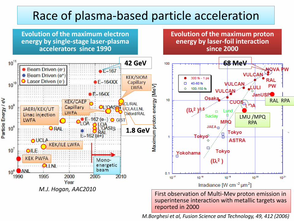
Race of plasma-based particle acceleration Race of plasma-based particle acceleration
M.Borghesi et al, Fusion Science and Technology, 49, 412 (2006)
M.J. Hogan, AAC2010
Evolution of the maximum electron Evolution of the maximum electron energy by single-stage laser-plasma
accelerators since 1990
Evolution of the maximum proton Evolution of the maximum proton energy by laser-foil interaction
since 2000
First observation of Multi-Mev proton emission in superintense interaction with metallic targets was reported in 2000
First observation of Multi-Mev proton emission in superintense interaction with metallic targets was reported in 2000
LMU /MPQ LMU /MPQ RPA
RAL RPARAL RPA
42 GeV42 GeV
1.8 GeV1.8 GeV
68 MeV68 MeV
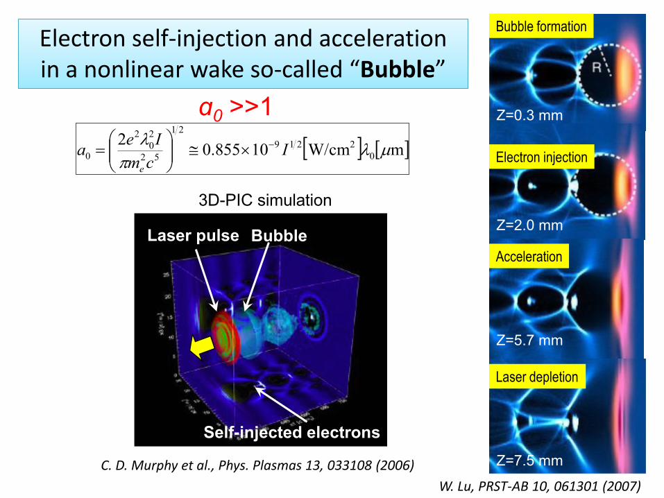
Laser pulse Bubble
Self-injected electrons
C. D. Murphy et al., Phys. Plasmas 13, 033108 (2006)
Z=0.3 mm
Z=2.0 mm
Z=5.7 mm
Z=7.5 mm
W. Lu, PRST-AB 10, 061301 (2007)
Bubble formation
Electron injection
Acceleration
Laser depletion
Electron self-injection and acceleration Electron self-injection and acceleration in a nonlinear wake so-called “Bubble”
3D-PIC simulation
ɑ0 >>1
mW/cm10855.02
0
2219
21
52
2
0
2
0
I
cm
Iea
e
34
0
32
3-
1831
m
8.0
cm
10
100
TW7.1GeV
pn
PW
100
TW8.3GeV
32
P
P
PW
c
3132
0
216.0
e
c
r n
n
P
P
w
cmcW
0aRk bp
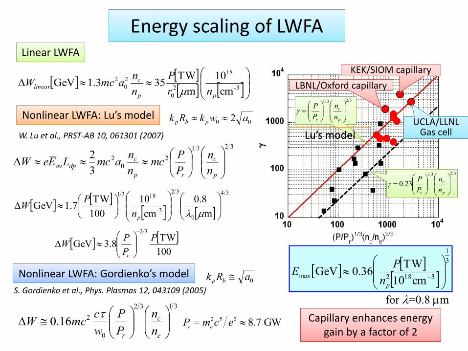
Linear LWFALinear LWFA
Nonlinear LWFA: Lu’s modelNonlinear LWFA: Lu’s model
Nonlinear LWFA: Gordienko’s modelNonlinear LWFA: Gordienko’s model
W. Lu et al., PRST-AB 10, 061301 (2007)
S. Gordienko et al., Phys. Plasmas 12, 043109 (2005)
3
1
3182maxcm10
TW36.0GeV
pn
PE
for =0.8 m
Pr m
e
2c5 e2 8.7 GW
Lu’s modelLu’s model
323/1
p
c
r n
n
P
P
323/1
23.0
p
c
r n
n
P
P
Energy scaling of LWFA Energy scaling of LWFA
00 2 awkRk pbp
3-
18
2
0
2
0
2
cm
10
m
TW353.1GeV
pp
clinear
nr
P
n
namcW
3231
2
0
2
3
2
p
c
rp
cdpav
n
n
P
Pmc
n
namcLEeW
KEK/SIOM capillaryKEK/SIOM capillary
LBNL/Oxford capillaryLBNL/Oxford capillary
UCLA/LLNLUCLA/LLNLGas cell
Capillary enhances energy Capillary enhances energy gain by a factor of 2
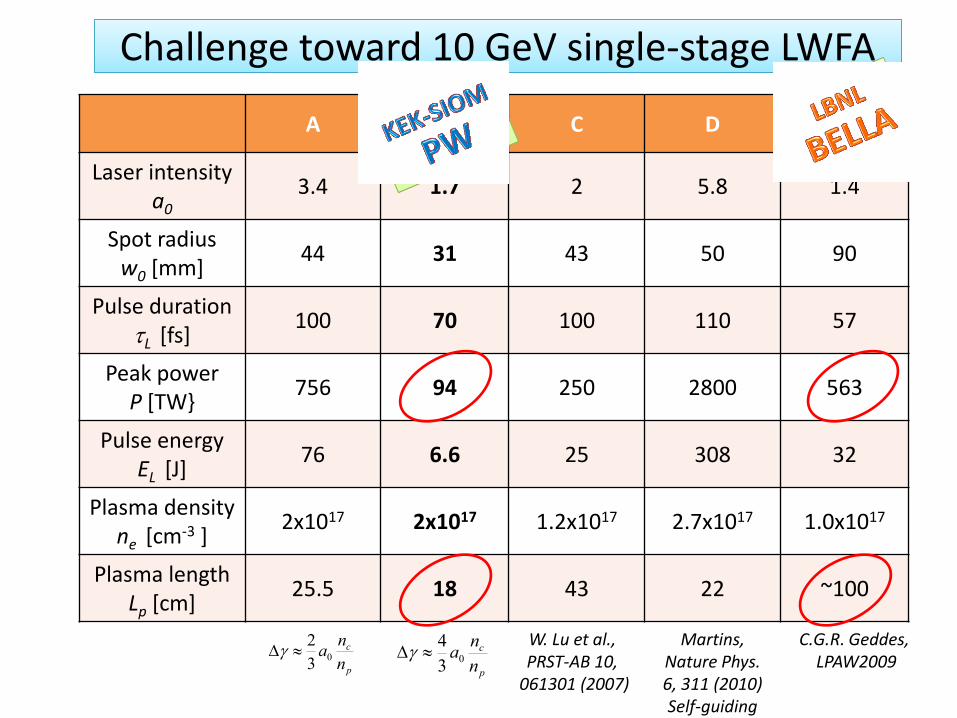
A B C D E
Laser intensitya0
3.4 1.7 2 5.8 1.4
Spot radius w0 [mm]
44 31 43 50 90
Pulse duration L [fs]
100 70 100 110 57
Peak power P [TW}
756 94 250 2800 563
Pulse energy EL [J]
76 6.6 25 308 32
Plasma density ne [cm-3 ]
2x10¹⁷ 2x10¹⁷ 1.2x10¹⁷ 2.7x10¹⁷ 1.0x10¹⁷
Plasma lengthLp [cm]
25.5 18 43 22 ~100
Challenge toward 10 GeV single-stage LWFAChallenge toward 10 GeV single-stage LWFA
p
c
n
na0
3
2
p
c
n
na0
3
4
Martins, Nature Phys. 6, 311 (2010)Self-guiding
W. Lu et al., PRST-AB 10,
061301 (2007)
C.G.R. Geddes, LPAW2009
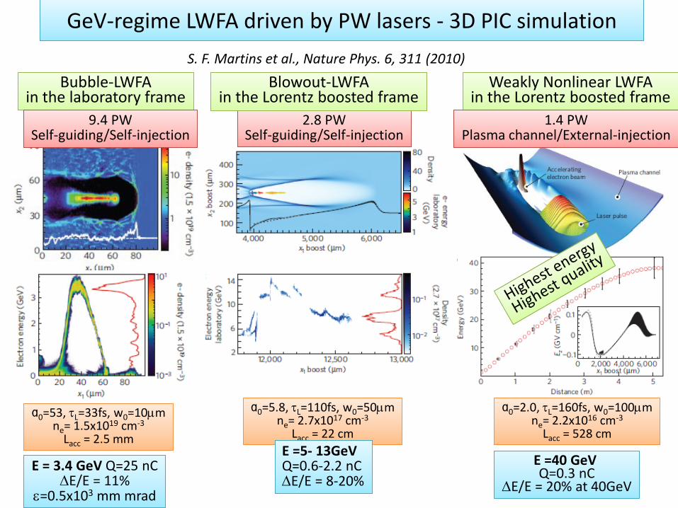
GeV-regime LWFA driven by PW lasers - 3D PIC simulation
S. F. Martins et al., Nature Phys. 6, 311 (2010)
Bubble-LWFAin the laboratory frame
Bubble-LWFAin the laboratory frame
ɑ =53, =33fs, w =10mɑ0=53, L=33fs, w0=10mne= 1.5x1019 cm-3
Lacc = 2.5 mm
9.4 PWSelf injection
9.4 PWSelf-guiding/Self-injection
E = 3.4 GeV Q=25 nCE = 3.4 GeV Q=25 nCE/E = 11%
e=0.5x103 mm mrad
2.8 PWSelf injection
2.8 PWSelf-guiding/Self-injection
Blowout-LWFAin the Lorentz boosted frame
Blowout-LWFAin the Lorentz boosted frame
ɑ =5.8, =110fs, w =50mɑ0=5.8, L=110fs, w0=50mne= 2.7x1017 cm-3
Lacc = 22 cm
E =5- 13GeV Q=0.6 20%
E =5- 13GeV Q=0.6-2.2 nCE/E = 8-20%
Weakly Nonlinear LWFAin the Lorentz boosted frame
Weakly Nonlinear LWFAin the Lorentz boosted frame
1.4 PWPlasma channel/External
1.4 PWPlasma channel/External-injection
ɑ =2.0, =160fs, w =100mɑ0=2.0, L=160fs, w0=100mne= 2.2x1016 cm-3
Lacc = 528 cm
E =40 GeV
E/E = 20% at 40GeV
E =40 GeVQ=0.3 nC
E/E = 20% at 40GeV
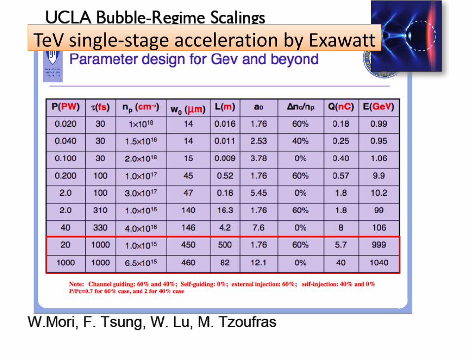
TeV single-stage acceleration by ExawattTeV single-stage acceleration by Exawatt
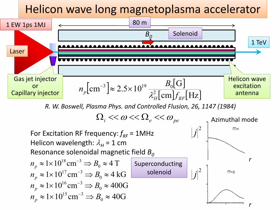
Hzcm
G105.2cm
2
0193
RFH
pf
Bn
R. W. Boswell, Plasma Phys. and Controlled Flusion, 26, 1147 (1984)
peei
B0
Helicon wave long acceleratorHelicon wave long magnetoplasma accelerator
For Excitation RF frequency: fRF = 1MHz Helicon wavelength: H = 1 cmResonance solenoidal magnetic field B0
T4cm101 0
318 Bnp
kG4cm101 0
317 BnpG400cm101 0
316 Bnp
G40cm101 0
315 Bnp
r
r
Azimuthal mode2j
2j
Gas jet injector
Capillary injector
Gas jet injectoror
Capillary injector
LaserLaser
Helicon wave Helicon wave excitation antenna
80 m80 m1 EW 1ps 1MJ1 EW 1ps 1MJ
1 TeV1 TeV
SolenoidSolenoid
Superconducting Superconducting solenoid
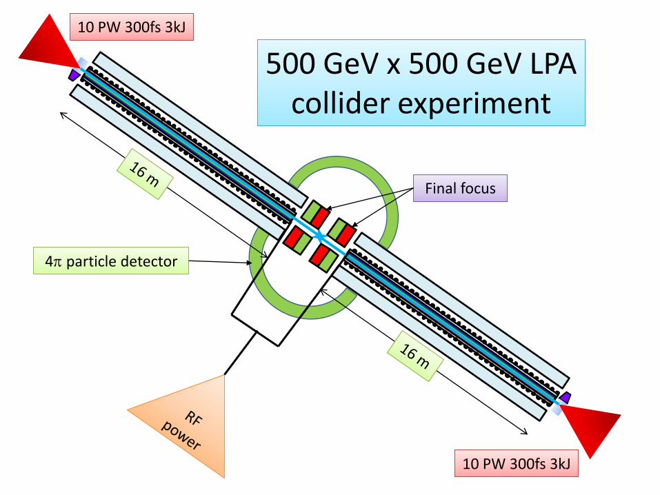
10 PW 300fs 3kJ10 PW 300fs 3kJ
10 PW 300fs 3kJ10 PW 300fs 3kJ
500 GeV x 500 GeV LPA 500 GeV x 500 GeV LPA collider experiment
Final focusFinal focus
4 particle detector4 particle detector
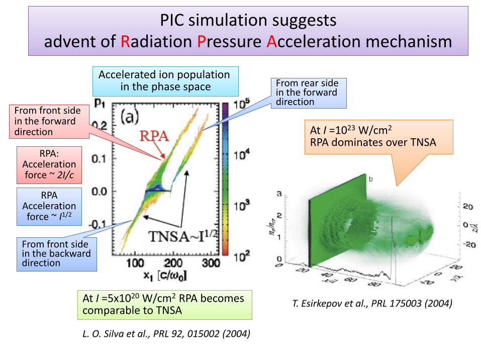
PIC simulation suggests PIC simulation suggests advent of Radiation Pressure Acceleration mechanism
L. O. Silva et al., PRL 92, 015002 (2004)
RPA:Acceleration
RPA:Acceleration force ~ 2I/c
From rear side in the forward direction
From rear side in the forward direction
From front side in the backward direction
From front side in the backward direction
From front side in the forward direction
From front side in the forward direction
T. Esirkepov et al., PRL 175003 (2004)
At I =10 W/cmRPA dominates over TNSAAt I =1023 W/cm2
RPA dominates over TNSA
RPAAcceleration
RPAAcceleration force ~ I1/2
At I =5x10²⁰ W/cm2 RPA becomes comparable to TNSAAt I =5x10²⁰ W/cm2 RPA becomes comparable to TNSA
Accelerated ion population Accelerated ion population in the phase space
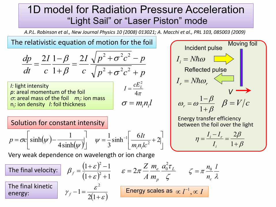
1D model for Radiation Pressure Acceleration1D model for Radiation Pressure Acceleration“Light Sail” or “Laser Piston” mode
pcp
pcp
c
I
c
I
dt
dp
222
2222
1
12
The relativistic equation of motion for the foilThe relativistic equation of motion for the foil
Solution for constant intensitySolution for constant intensity
I: light intensitypn
I: light intensityp: areal momentum of the foil: areal mass of the foil mi: ion mass ni: ion density l: foil thickness
4
2
LcEI
lnm ii
sinh4
1sinhcp
2
6sinh
3
12
1
lcnm
It
ii
V
NIi
rr NI
Incident pulse
Reflected pulse
Moving foil
1
1r cV
Energy transfer efficiency between the foil over the light
1
2
i
ri
I
II
The final velocity:The final velocity: 11
112
2
e
e f
A.P.L. Robinson et al., New Journal Physics 10 (2008) 013021; A. Macchi et al., PRL 103, 085003 (2009)
e L
p
e a
m
m
A
Z 2
02
l
n
n
c
0
Very weak dependence on wavelength or ion charge
ee
12
12
f
The final kinetic energy:The final kinetic energy: Energy scales as Il ,1
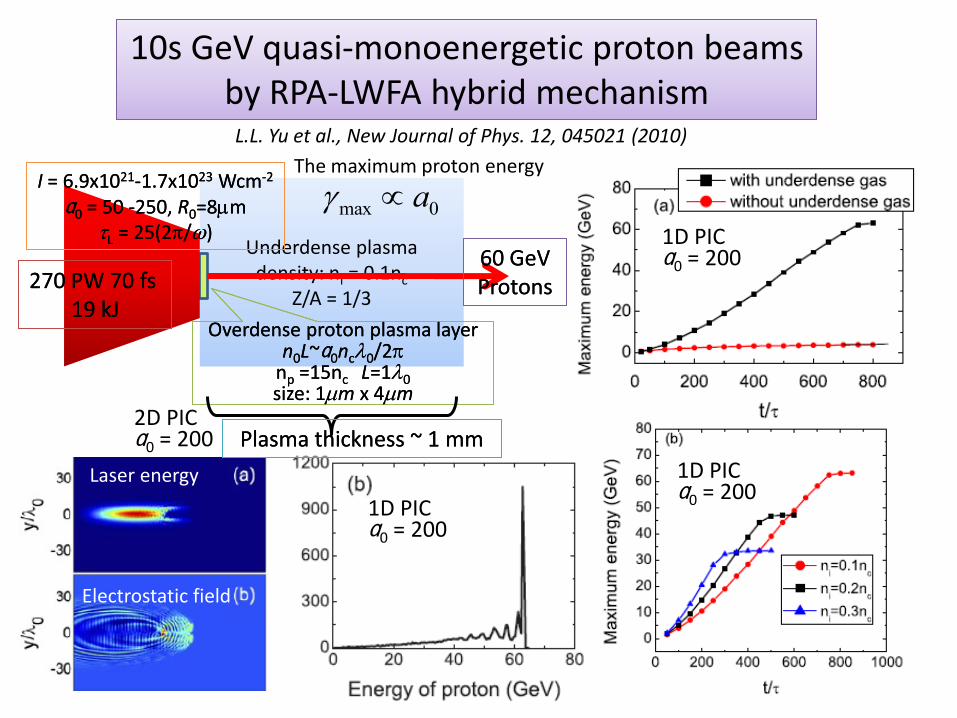
Underdense plasmadensity: ni = 0.1nc
Z/A = 1/3
10s GeV quasi-monoenergetic proton beams10s GeV quasi-monoenergetic proton beamsby RPA-LWFA hybrid mechanism
L.L. Yu et al., New Journal of Phys. 12, 045021 (2010)
I = 6.9x10²¹-1.7x10²³ Wcm-2
ɑ0 = 50 -250, R0=8mL = 25(2/)
I = 6.9x10²¹-1.7x10²³ Wcm-2
ɑ0 = 50 -250, R0=8mL = 25(2/)
Overdense proton plasma layer n0L~ɑ0nc0/2
np =15nc L=10 size: 1m x 4m
Overdense proton plasma layer n0L~ɑ0nc0/2
np =15nc L=10 size: 1m x 4m
1D PICɑ0 = 200
1D PICɑ0 = 200
1D PICɑ0 = 200
2D PICɑ0 = 200
Laser energy
Electrostatic field
0max aThe maximum proton energy
270 PW 70 fs19 kJ
270 PW 70 fs19 kJ
60 GeVProtons60 GeVProtons
Plasma thickness ~ 1 mmPlasma thickness ~ 1 mm
Virtual photonVirtual photon
e-e- e-e-
e in the laser e- in the laser field
e+e+
Coulomb fieldCoulomb fieldof nuclear charge Z
Virtual photonVirtual photon
mec2
0
E
V0
V0 -mec2
V0 +mec2
e+
e-e-
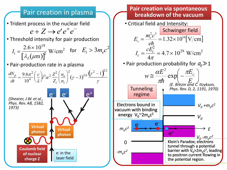
dNp
dt
9.6 2
104
c
l3 2 Z2
Zi
ne
nc
2
3 3.6 2 1
1 2
e Z e ee
Ei 3mec2
It 2.61019
L m 2 W/cm
2
Pair creation in plasmaPair creation in plasma
• Trident process in the nuclear field
• Threshold intensity for pair production
• Pair-production rate in a plasma
Pair creation via spontaneous Pair creation via spontaneous breakdown of the vacuum
Ic cEc
2
4 4.7 10
29W/cm
2
• Critical field and Intensity:
for
cmV1032.1 1632
e
cmE ec
Schwinger fieldSchwinger field
(Shearer, J.W. et al., Phys. Rev. A8, 1582, 1973)
• Pair production probability for ɑ0≫1
E
EEw c
exp
2
(E. Brezin and C. Itzykson, Phys. Rev. D, 2, 1191, 1970)Tunneling Tunneling
regime
Electrons bound in vacuum with binding
energy V0~2mec2
Electrons bound in vacuum with binding
energy V0~2mec2
Klein’s Paradox; electrons tunnel through a potential barrier with V0>2mec2, leading to positron current flowing in the potential region.
Klein’s Paradox; electrons tunnel through a potential barrier with V0>2mec2, leading to positron current flowing in the potential region.
-mec2
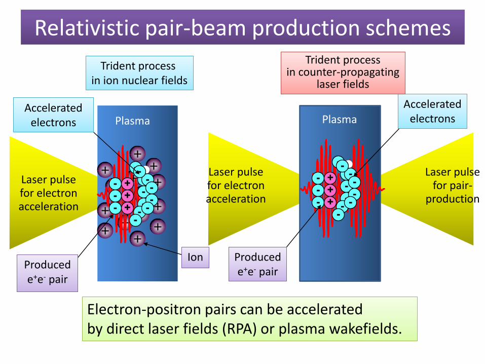
Relativistic pair-beam production schemesRelativistic pair-beam production schemes
+
++
+
++
+
+
+
+
+
+
+
+
+
----
-
--
--
-
----
++
+
IonIon
AcceleratedAcceleratedelectrons
ProducedProducede+e- pair
Plasma
Trident process in ion nuclear fields
Trident process in ion nuclear fields
----
-
--
--
-
----
++
+
AcceleratedAcceleratedelectrons
ProducedProducede+e- pair
Plasma
Laser pulsefor electronacceleration
Laser pulsefor electronacceleration
Laser pulsefor pair-
production
Trident processin counter propagating
Trident processin counter-propagating
laser fields
Electron-positron pairs can be accelerated by . Electron-positron pairs can be accelerated by direct laser fields (RPA) or plasma wakefields.
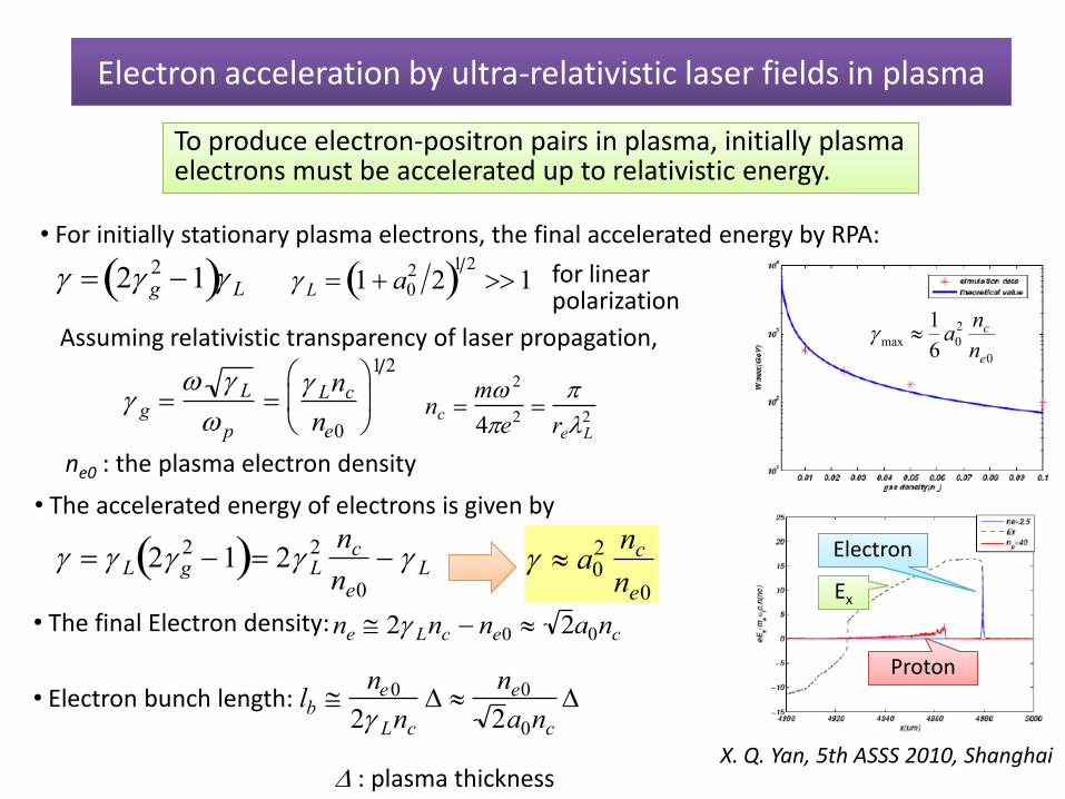
Electron acceleration by ultra-relativistic laser fields in plasma
• For initially stationary plasma electrons, the final accelerated energy by RPA:
2 g21 L L 1 a0
22
1 21
Assuming relativistic transparency of laser propagation,
g L
p
Lnc
ne0
1 2
nc m 2
4e2
reL2
• The accelerated energy of electrons is given by
L 2 g2 1 2 L
2 nc
ne0
L
To produce electron-positron pairs in plasma, initially plasma electrons must be To produce electron-positron pairs in plasma, initially plasma electrons must be accelerated up to relativistic energy.
a02 nc
ne0
• The final Electron density:ne 2 Lnc ne0 2a0nc
• Electron bunch length: lb ne0
2 Lnc
ne0
2a0nc
ne0 : the plasma electron density
for linear polarization
: plasma thickness
0
2
0max6
1
e
c
n
na
X. Q. Yan, 5th ASSS 2010, Shanghai
ProtonProton
ElectronElectron
EEx
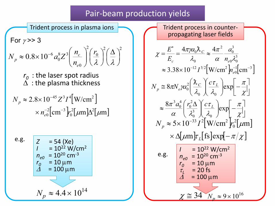
Trident process in plasma ions Trident process in plasma ions
Pair-beam production yieldsPair-beam production yields
22
0
2
0
38
0
6108.0
r
n
nZaN
e
cp
For >> 3
r0 : the laser spot radius : the plasma thickness
mmcm
W/cm108.2
22
0
32
0
24345
rn
IZN
e
p
e.g.
Np 4.4 1014
Z = 54 (Xe)I nr
Z = 54 (Xe)I = 1022 W/cm2
ne0 = 1020 cm-3
r0 = 10 m = 100 m
Trident process in counter-Trident process in counter-propagating laser fields
31
0
22312
3
00
3
0
2
0
0
cmW/cm1038.3
44
e
e
C
c
nI
n
aa
E
E
exp8
exp8
0
3
0
2
0
4
0
3
00
2
0
L
LCep
cra
caNN
expfsm
mW/cm105 2
0
2233
L
p rIN
I = 1022 W/cm2
nr
I = 1022 W/cm2
ne0 = 1020 cm-3
r0 = 10 mL = 20 fs = 100 m
34 Np 9 1016
e.g.
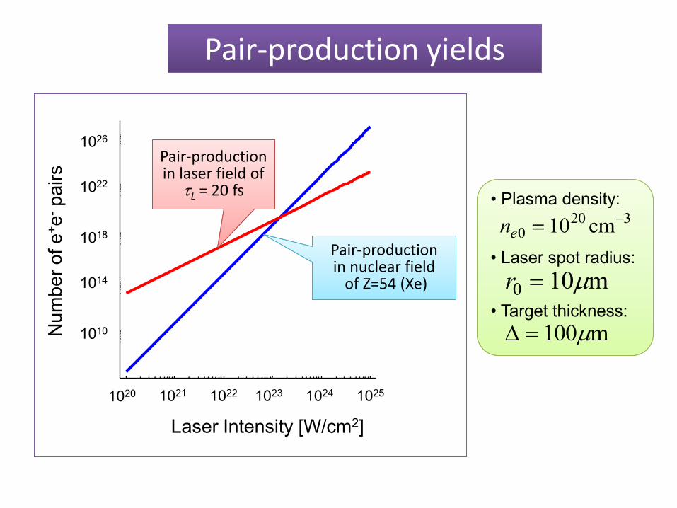
Pair-production yieldsPair-production yields
1020 1021 1022 1023 1024 1025
Laser Intensity [W/cm2]
1010
1014
1018
1022
1026
Nu
mb
er
of e
+e
-p
air
s
Pair-production Pair-production in nuclear field
of Z=54 (Xe)
Pair productionPair-productionin laser field of
L = 20 fs
ne0 1020 cm3
r0 10m
100m
• Plasma density:
• Laser spot radius:
• Target thickness:
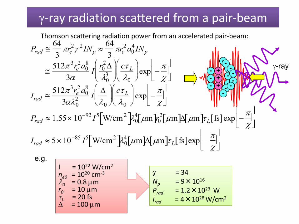
-ray radiation scattered from a pair-beam-ray radiation scattered from a pair-beamThomson scattering radiation power from an accelerated pair-beam:
Prad 64
3re
2 2INp 64
3re
2a04INp
Irad 5123re
2a08
302 I
0
c L
0
exp
Prad 1.551092 I 5 W/cm 2 04 m r0
2 m m L fs exp
e.g.
For
512 3re
2a08
3I
r02
03
c L
0
exp
Irad 5 1085 I5 W/cm2 04 m m L fs exp
----
-
--
--
-
----
++
+
-ray
I = 10nr
I = 1022 W/cm2
ne0 = 1020 cm-3
0 = 0.8 mr0 = 10 mL = 20 fs = 100 m
= 34NPI
= 34Np = 9×10¹⁶
Prad = 1.2×10²³ WIrad = 4×1028 W/cm2
Intensity
Radius
ElectronElectron
Fpond Fpond
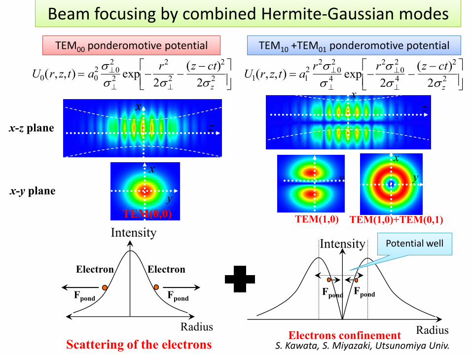
Scattering of the electrons
x
z
x
x-z plane
x-y plane
z
x
y
x
TEM(0,0)
y
TEM(1,0)
x
y
TEM(1,0)+TEM(0,1)
U0 r, z,t a02 0
2
2 exp
r2
22
z ct 2
2 z2
U1 r, z,t a1
2 r202
4 exp
r2 02
24
z ct 2
2 z2
TEM ponderomotive potentialTEM00 ponderomotive potential TEM +TEM ponderomotive potentialTEM10 +TEM01 ponderomotive potential
Intensity
Radius
FpondFpond
Electrons confinement
Potential well
S. Kawata, S. Miyazaki, Utsunomiya Univ.
Beam focusing by combined Hermite-Gaussian modes
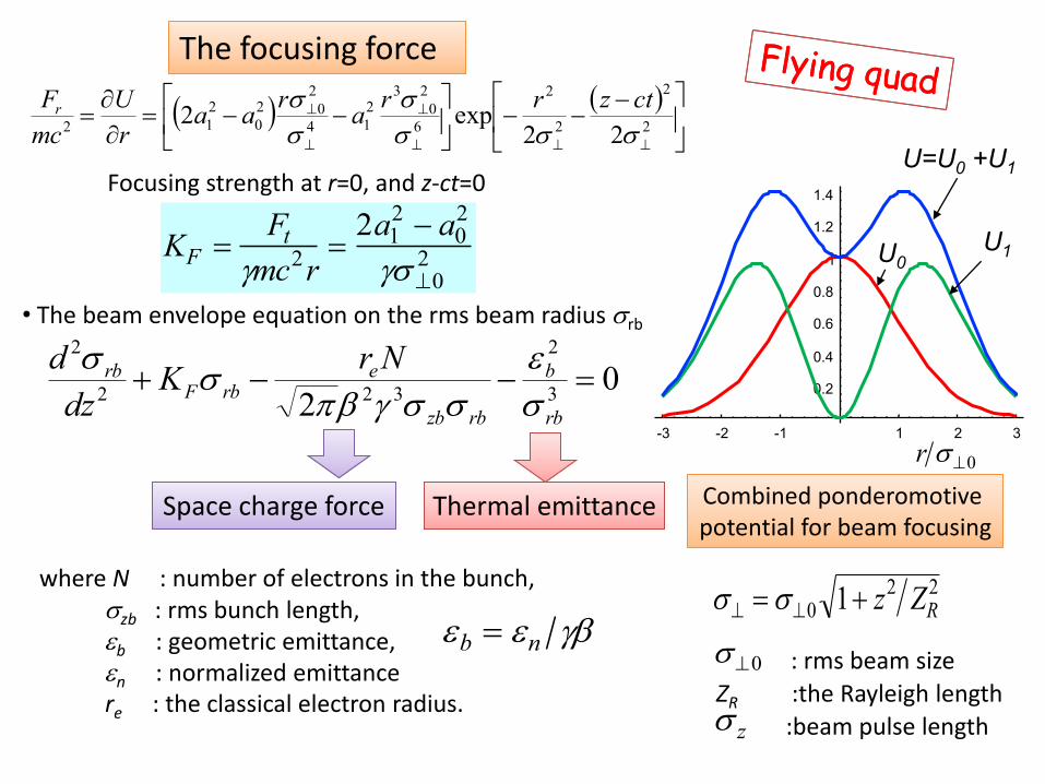
Focusing strength at r=0, and z-ct=0
KF Ft
mc2r
2a12 a0
2
02
• The beam envelope equation on the rms beam radius rb
02 3
2
322
2
rb
b
rbzb
erbF
rb NrK
dz
d
e
where N : number of electrons in the bunch,zb : rms bunch length, eb : geometric emittance,en : normalized emittancere : the classical electron radius.
eb en
Space charge forceSpace charge force Thermal emittanceThermal emittance
The focusing forceThe focusing force
2
2
2
2
6
2
0
32
14
2
02
0
2
12 22exp2
ctzrra
raa
r
U
mc
Fr
-3 -2 -1 1 2 3
0.2
0.4
0.6
0.8
1
1.2
1.4
U0U1
U=U0 +U1
r 0
Combined ponderomotivepotential for beam focusingCombined ponderomotivepotential for beam focusing
0 : rms beam size
ZR :the Rayleigh length z :beam pulse length
0 1 z2
ZR2
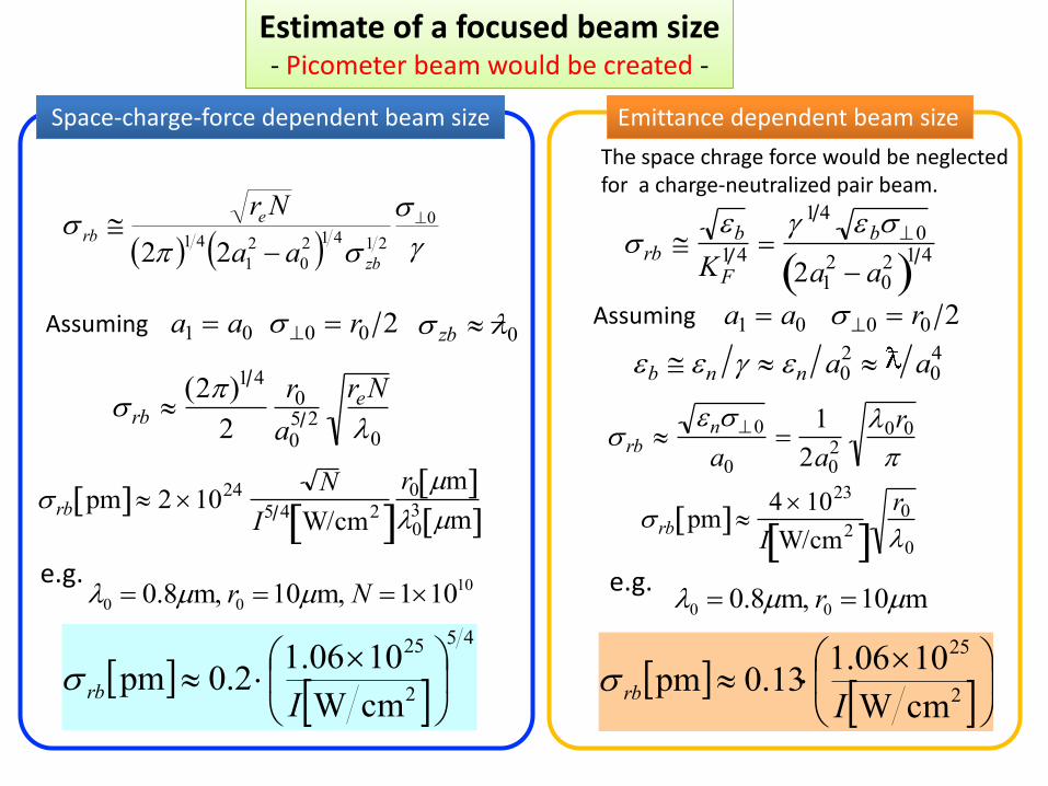
Estimate of a focused beam sizeEstimate of a focused beam size- Picometer beam would be created -
0
21412
0
2
1
4122
zb
erb
aa
Nr
a1 a0Assuming 0 r0 2 zb 0
rb 2 1 4
2
r0
a05 2
reN
0
rb pm 2 1024 N
I5 4 W/cm2 r0 m 0
3 m
e.g.10
00 101 m,10 m,8.0 Nr
45
2
25
cmW
1006.12.0pm
I
rb
Assuming a1 a0
rb en0
a0
1
2a02
0r0
eb en en a02 a0
4
0 r0 2
rb pm 4 1023
I W/cm2 r0
0
rb eb
KF1 4
1 4 eb0
2a12 a0
2 1 4
e.g.
The space chrage force would be neglected for a charge-neutralized pair beam.
m10 m,8.0 00 r
2
25
cmW
1006.113.0pm
Irb
Space-charge-force dependent beam sizeSpace-charge-force dependent beam size Emittance dependent beam sizeEmittance dependent beam size
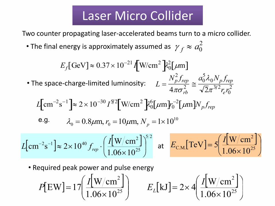
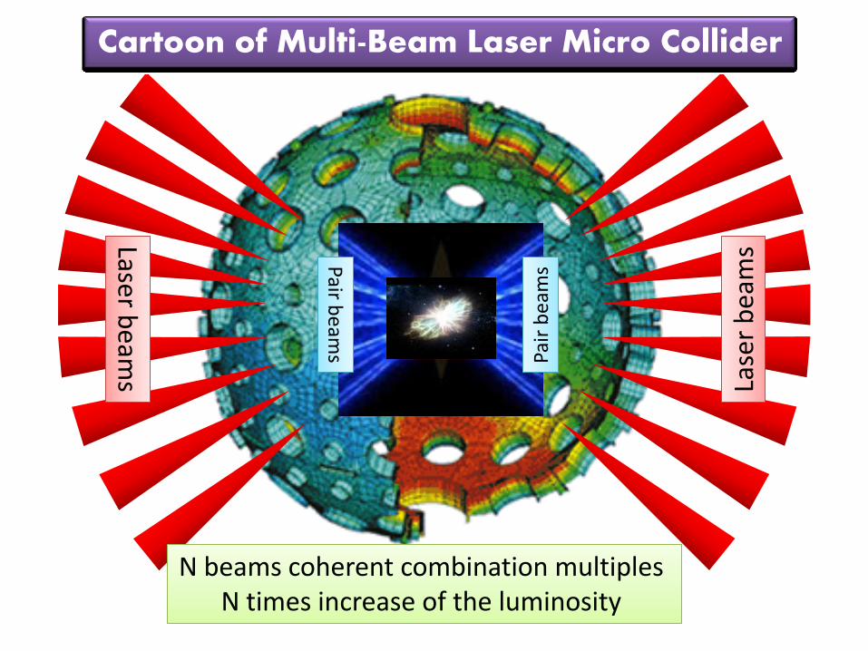
Laser Micro ColliderLaser Micro ColliderTwo counter propagating laser-accelerated beams turn to a micro collider.
• The space-charge-limited luminosity: L Np
2 frep
4 rb2
a050Np frep
2 3 2rer02
L cm2s1 2 1030 I5 2 W/cm2 06 m r0
2 m N p frep
25
2
C.M.101.06
cmW5TeVI
E
e.g.
25
25
24012
1006.1
cmW102scm
I
fL rep
• Required peak power and pulse energy
• The final energy is approximately assumed as f a02
E f GeV 0.37 1021 I W/cm2 02 m
10
00 101 m,10 m,8.0 pNr
at
25
2
101.06
cmW17EW
IP
25
2
101.06
cmW42kJI
EL
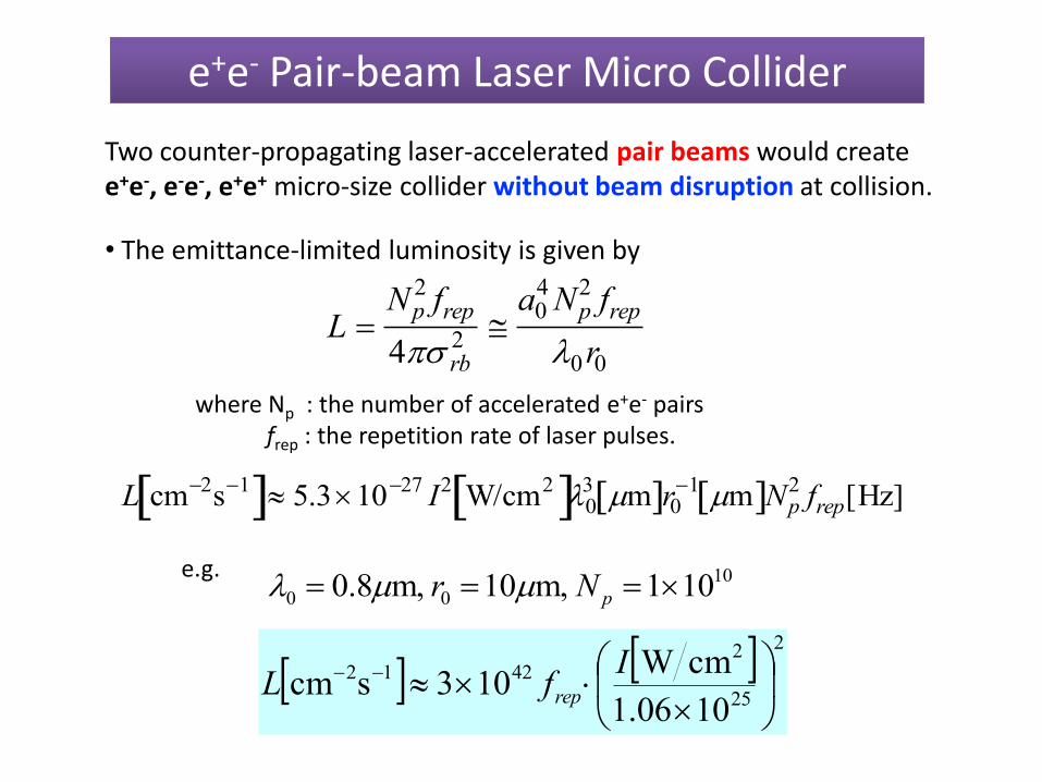
e+e- Pair-beam Laser Micro Collidere+e- Pair-beam Laser Micro Collider
Two counter-propagating laser-accelerated pair beams would createe+e-, e-e-, e+e+ micro-size collider without beam disruption at collision.
L Np
2 frep
4 rb2
a04 Np
2 frep
0r0
• The emittance-limited luminosity is given by
where Np : the number of accelerated e+e- pairs frep : the repetition rate of laser pulses.
L cm2s1 5.31027 I2 W/cm2 03 m r0
1 m Np2 frep[Hz]
e.g.
2
25
24212
101.06
cmW103scm
I
fL rep
10
00 101 m,10 m,8.0 pNr
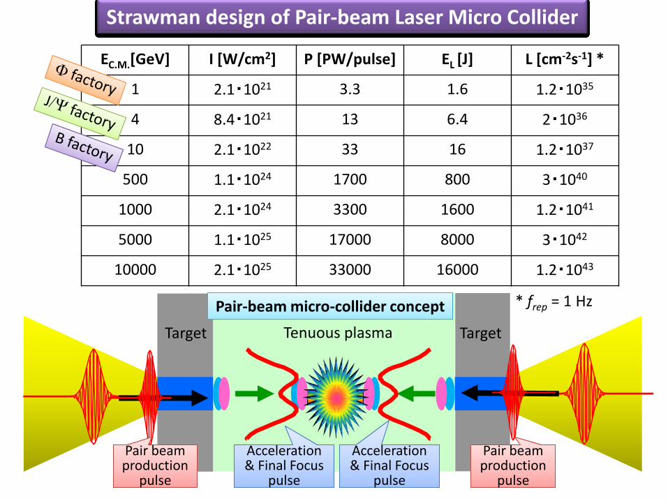
EC.M.[GeV] I [W/cm2] P [PW/pulse] EL [J] L [cm-2s-1] *
1 2.1・1021 3.3 1.6 1.2・1035
4 8.4・1021 13 6.4 2・1036
10 2.1・1022 33 16 1.2・1037
500 1.1・1024 1700 800 3・1040
1000 2.1・1024 3300 1600 1.2・1041
5000 1.1・1025 17000 8000 3・1042
10000 2.1・1025 33000 16000 1.2・1043
* frep = 1 HzPair-beam micro-collider conceptPair-beam micro-collider concept
Tenuous plasmaTarget Target
Strawman design of Pair-beam Laser Micro Collider
Pair beam
pulse
Pair beam production
pulse
Pair beam
pulse
Pair beam production
pulse
Acceleration & Final Focus
pulse
Acceleration & Final Focus
pulse
Acceleration & Final Focus
pulse
Acceleration & Final Focus
pulse
Laser beam
sLaser b
eams La
ser
bea
ms
Lase
r b
eam
sPair be
ams
Pair be
ams Pa
ir b
eam
sPa
ir b
eam
s
Cartoon of Multi-Beam Laser Micro Collider
N beams coherent combination multiples N beams coherent combination multiples N times increase of the luminosity
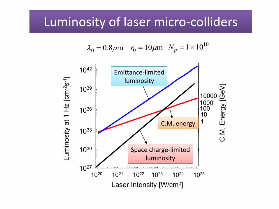
Luminosity of laser micro-collidersLuminosity of laser micro-colliders
1042
1039
1036
1033
1030
1027
Lum
inosity a
t 1 H
z [cm
-2s
-1]
100
110
C.M
. E
nerg
y [
GeV
]
100010000
1020 1021 1022 1023 1024 1025
Laser Intensity [W/cm2]
C.M. energyC.M. energy
Emittance-limitedEmittance-limitedluminosity
Space charge-limitedSpace charge-limitedluminosity
0 0.8m r0 10m Np 11010
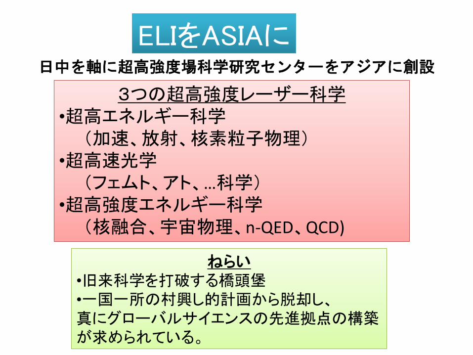
ELIをASIAにELIをASIAに日中を軸に超高強度場科学研究センターをアジアに創設
3つの超高強度レーザー科学•
•
•
3つの超高強度レーザー科学•超高エネルギー科学(加速、放射、核素粒子物理)
•超高速光学(フェムト、アト、…科学)
•超高強度エネルギー科学(核融合、宇宙物理、n-QED、QCD)
ねらい•
•
真にグローバルサイエンスの先進拠点の構築が求められている。
ねらい•旧来科学を打破する橋頭堡•一国一所の村興し的計画から脱却し、真にグローバルサイエンスの先進拠点の構築が求められている。
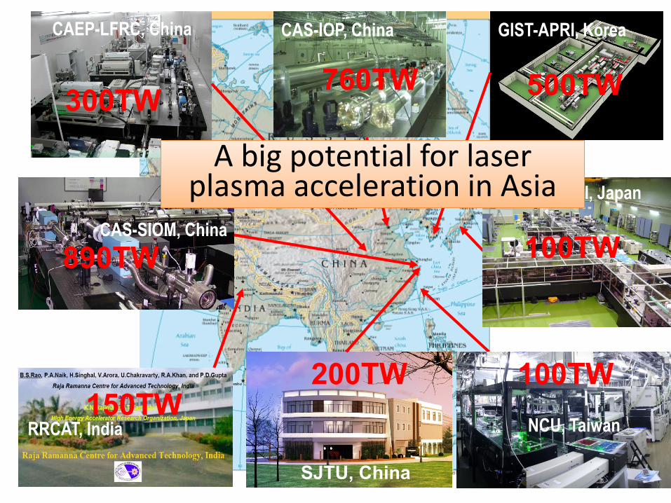
CAS-IOP, ChinaCAEP-LFRC, China
300TW760TW
GIST-APRI, Korea
500TW
JAEA-KPSI, Japan
100TW
RRCAT, India150TW
NCU, Taiwan
100TW
CAS-SIOM, China
890TW
A big potential for laser A big potential for laser plasma acceleration in Asia
200TW
SJTU, China
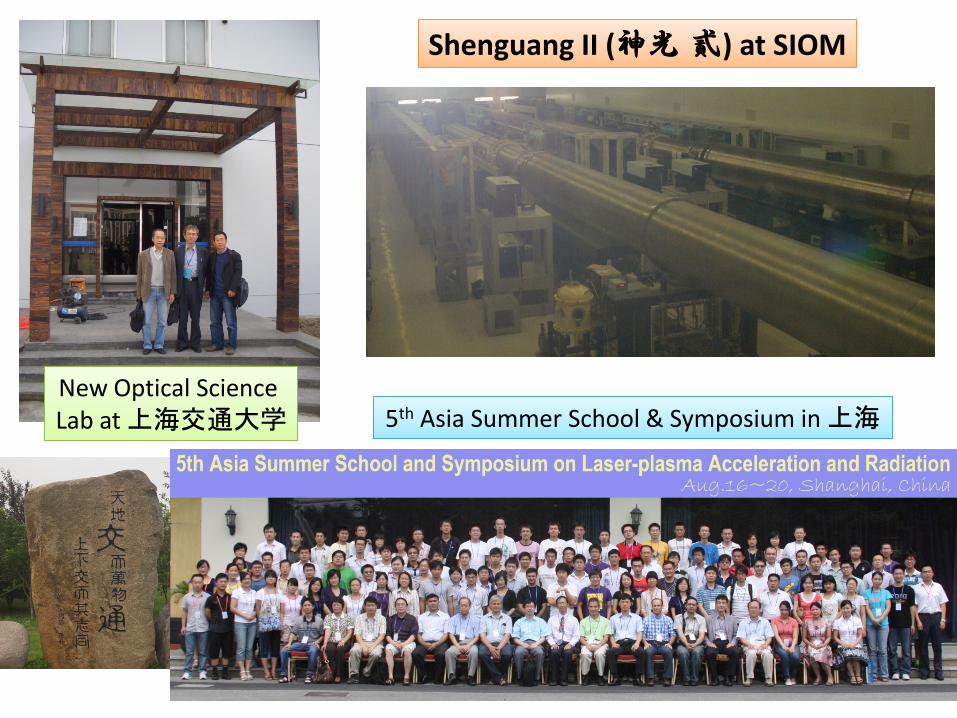
Shenguang II (神光 貳) at SIOMShenguang II (神光 貳) at SIOM
New Optical Science Lab at 上海交通大学New Optical Science Lab at 上海交通大学 5 Asia Summer School & Symposium in 上海5th Asia Summer School & Symposium in 上海