Embed Size (px)
Citation preview
ARTICLE
Exceptional catalytic effects of black phosphorusquantum dots in shuttling-free lithium sulfurbatteriesZheng-Long Xu1,2, Shenghuang Lin1, Nicolas Onofrio1, Limin Zhou3, Fangyi Shi3, Wei Lu1, Kisuk Kang2,
Qiang Zhang 4 & Shu Ping Lau 1
Lithium sulfur batteries with high energy densities are promising next-generation energy
storage systems. However, shuttling and sluggish conversion of polysulfides to solid lithium
sulfides limit the full utilization of active materials. Physical/chemical confinement is useful
for anchoring polysulfides, but not effective for utilizing the blocked intermediates. Here, we
employ black phosphorus quantum dots as electrocatalysts to overcome these issues. Both
the experimental and theoretical results reveal that black phosphorus quantum dots effec-
tively adsorb and catalyze polysulfide conversion. The activity is attributed to the numerous
catalytically active sites on the edges of the quantum dots. In the presence of a small amount
of black phosphorus quantum dots, the porous carbon/sulfur cathodes exhibit rapid reaction
kinetics and no shuttling of polysulfides, enabling a low capacity fading rate (0.027% per
cycle over 1000 cycles) and high areal capacities. Our findings demonstrate application of a
metal-free quantum dot catalyst for high energy rechargeable batteries.
DOI: 10.1038/s41467-018-06629-9 OPEN
1 Department of Applied Physics, The Hong Kong Polytechnic University, Hong Kong, China. 2 Department of Materials Science and Engineering, ResearchInstitute of Advanced Materials (RIAM), and Center for Nanoparticle Research at Institute of Basic Science (IBS), Seoul National University, Seoul 08826,Republic of Korea. 3 Department of Mechanical Engineering, The Hong Kong Polytechnic University, Hong Kong, China. 4 Beijing Key Laboratory of GreenChemical Reaction Engineering and Technology, Department of Chemical Engineering, Tsinghua University, 100084 Beijing, China. These authors contributedequally: Zheng-Long Xu, Shenghuang Lin, Nicolas Onofrio. Correspondence and requests for materials should be addressed toQ.Z. (email: [email protected]) or to S.P.L. (email: [email protected])
NATURE COMMUNICATIONS | (2018) 9:4164 | DOI: 10.1038/s41467-018-06629-9 | www.nature.com/naturecommunications 1
1234
5678
90():,;
The development of portable electronic devices drives asearch for energy storage systems with lower cost, higherenergy density, and better safety than current Li-ion bat-
teries. Among alternative batteries, lithium-sulfur batteries (LSBs)generate interest due to advantages of a high energy density of2600W h kg−1 and the low cost of sulfur feedstock1,2. However,the practical application of LSBs has been plagued by severalfundamental challenges3–5, including the insulating nature ofsulfur and lithium sulfides, the large volume expansion of sulfur,and the diffusion of lithium polysulfides (LiPSs) intermediatesduring charge/discharge cycles. The last obstacle further inducesshuttling effects, self-discharge phenomena, and re-distribution ofactive particles, leading to rapid capacity degradation. Therefore,achieving the confinement of polysulfides in cathodes is a highpriority among the primary research of LSBs.
Research over the past decade has brought progress in stabi-lizing LiPSs by physical and chemical immobilization approaches.Carbon nanomaterials have been systematically designed withhigh electrical conductivities, desirable pores, and controlleddimensions to host sulfur particles to physically confine LiPSs6–9.Unfortunately, weak interactions between non-polar carbon andpolar LiPSs lead to failure in long-term performance of LSBs,causing gradual capacity decay and poor rate performance10.Chemical trapping of LiPSs with a polar host11, such as N-dopedcarbon12 and metal dichalchogenide13, has proven effective forpreventing diffusion of LiPSs via polar–polar interactions14 orLewis acid-based bonding.15 However, in most cases, chemicalimmobilization is rather limited for improving battery perfor-mance because the blocked LiPSs cannot be effectivelyreused16,17. For example, LiPSs can be strongly adsorbed by TiO2,but full conversion to Li2S is difficult due to the low electricalconductivity of TiO2
18. Although polar, conductive chemicaltraps, such as CoS219 and WS220, have been prepared as sulfurhosts, the high gravimetric density of metal-containing com-pounds and the limited number of adsorption sites discourageshigh energy density of sulfur cathodes. Therefore, the effectivetrapping and conversion of LiPSs remain as important challengestoward achieving high-performance LSBs.
Black phosphorus (BP) is the most thermodynamically stableallotrope of phosphorus, with low resistivity ranging between 0.48and 0.77Ω cm21 and an exceptionally high room-temperature holemobility of ~1000 cm2 V−1 s−1 22. BP also possesses a low densityof 2.69 g cm−3 23, a good bulk conductivity of ~3 S cm−1 24, a fastLi-ion diffusion constant25, and high binding energies withsulfur26. These properties suggest that BP can chemically bindwith LiPSs and convert them immediately to Li2S through goodelectrical conductivity and fast Li-ion diffusion, without dis-cernibly compensating the mass fraction of active materials. Few-layered BP flakes have been adopted in separators26 or currentcollectors27 to suppress the diffusion of LiPSs, leading toenhanced cyclic stability of LSBs. However, to trap flooded LSPsby the terrace sites of micro-sized BP flakes, a high loading(≈1 wt% with respect to the sulfur weight in electrodes) of BP wasemployed27. Considering the Li2S6 catholyte with a theoreticalcapacity of 1299 mA h g−1 that was used in that work, the 10 wt%of electrochemically inert BP may reduce the energy densityadvantage of LSBs. If edge sites of BP are also effective in trappingLiPSs, the amount of BP additives could be significantly decreasedby using nanoscale BP particles, for example, BP quantum dots(BPQDs).
In this contribution, we systematically investigate the catalyticproperties of the nanostructured BP and propose a metal-freeBPQD as a robust catalyst for advanced LSBs. Based on adsorp-tion and electrocatalytic studies, we find that the edge sites of thenanostructured BP are key to the effective immobilization ofLiPSs. The edge-selective catalytic property of the BPQDs is
further validated using density functional theoretical (DFT) cal-culations, where the zig-zag (ZZ) terminated BP flakes presentstronger binding energies with Li2S at the edges than at terracesites. These results suggest that adsorptivity of LiPS in BP can belargely increased by downsizing BP flakes to QDs. As a proof ofconcept, we integrate a small amount of BPQDs (2 wt% of thecathode weight) with a sulfur/porous carbon fiber cathode, theLSBs exhibit no diffusion of polysulfides as well as excellent bat-tery performance, including high-rate capability (784 mA h g−1 at4 C) and exceptional cyclic stability (0.027% capacity fade percycle for 1000 cycles). Finally, an impressive capacity retention ofnear 90% is observed for high sulfur loading cathodes (up to 8mg cm−1) for 200 deep cycles under lean electrolyte conditions.
ResultsRational design of a black phosphorus catalyst. Two-dimensional (2D)-layered crystals usually exhibit strong intera-tomic covalent bonding and weak interlayer van der Waalsinteractions, rendering different chemical activities of the atomsat terrace and edge sites. The edge sites tend to possess higherelectrochemical catalytic activity than the terrace counterparts incatalysis due to their under-coordinated atomic structures28–31.Understanding edge-selective catalytic feature is beneficial indesigning catalysts by downsizing the particle size to introducemore active sites. BP is a single-element layered material with onephosphorus atom bonded to three adjacent neighbors to form ahoneycomb network, similar to graphite and metaldichalcogenides.
To explore whether BP also possesses such unique edge-selective catalytic properties in LSBs, we rationally prepareddifferent-sized BP flakes through probe sonication and centrifu-gation of bulk BP crystals in N-methyl-2-pyrrolidone (NMP)solution32,33. The as-obtained BP products were designated asBP-4K, BP-8K according to their centrifugation rates of 4000 and8000 rpm, respectively, and BPQD (centrifuged at 12,000 rpm). Itis noted that the concentrations of the three BP solutions werecontrolled as about 0.55 mgmL−1, as determined by inductivecoupled plasma with atomic emission spectroscopy (ICP-AES)23.
Figure 1a and b shows the transmission electron microscopy(TEM) images of the BP-4K and BP-8K flakes, which reveal sizesof about 800 and 300 nm, respectively, indicating that smallerflakes were obtained at higher centrifugation rate. The structuralfeatures of the BP flakes were investigated by high-resolutionTEM (HRTEM) and the selected area electron diffraction patterns(SAED). As shown in Fig. 1c, the lattice constant of 0.21 nm isindexed to (002) plane of BP crystal34, consistent with the sharpdiffraction spots in the inset. The TEM image of the BPQD inFig. 1d shows an impressive monodispersion of the BPQDs. TheQD size is approximatively 4.5 nm with lattice fringes of 0.33 and0.21 nm (Fig. 1e, f), assigned to (021) and (002) planes of BPcrystal32,33, respectively. The dimensions of the three BP sampleswere also characterized with atomic force microscope (AFM).Supplementary Fig. 1 shows the BP-4K, BP-8K, and BPQD withthickness × particle size of about 6.1 × 800 nm, 4.3 × 300 nm, and2.5 × 4.5 nm, respectively. Based on the dimensions of different-sized BP flakes, we can roughly estimate the exposed edge densityby Sedge/Swhole, where Sedge and Swhole refer to the area of exposededge and the whole surface, respectively. For simplicity, we set theflake as a rectangle prism with two equal edge lengths and QD asa cylinder. The BP-4K, BP-8K and BPQD present Sedge/Swhole of1.5%, 2.8%, and 52.6%, respectively, implying the highest exposededge density of QD structure35. The chemical structure of theBPQDs was further probed by Raman spectroscopy. Figure 1gshows three featured Raman peaks at 360.8, 438.1, and 466.2 cm−1,referring to Ag
1, B2g, and Ag2 modes, respectively. Compared to
ARTICLE NATURE COMMUNICATIONS | DOI: 10.1038/s41467-018-06629-9
2 NATURE COMMUNICATIONS | (2018) 9:4164 | DOI: 10.1038/s41467-018-06629-9 | www.nature.com/naturecommunications
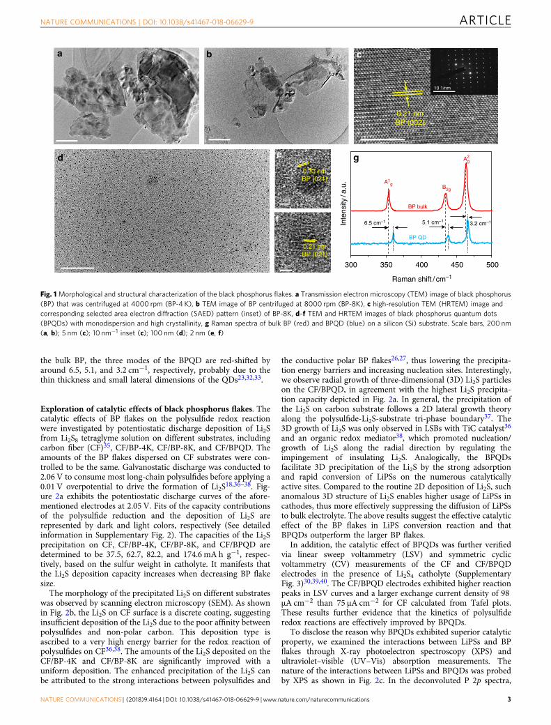
the bulk BP, the three modes of the BPQD are red-shifted byaround 6.5, 5.1, and 3.2 cm−1, respectively, probably due to thethin thickness and small lateral dimensions of the QDs23,32,33.
Exploration of catalytic effects of black phosphorus flakes. Thecatalytic effects of BP flakes on the polysulfide redox reactionwere investigated by potentiostatic discharge deposition of Li2Sfrom Li2S8 tetraglyme solution on different substrates, includingcarbon fiber (CF)35, CF/BP-4K, CF/BP-8K, and CF/BPQD. Theamounts of the BP flakes dispersed on CF substrates were con-trolled to be the same. Galvanostatic discharge was conducted to2.06 V to consume most long-chain polysulfides before applying a0.01 V overpotential to drive the formation of Li2S18,36–38. Fig-ure 2a exhibits the potentiostatic discharge curves of the afore-mentioned electrodes at 2.05 V. Fits of the capacity contributionsof the polysulfide reduction and the deposition of Li2S arerepresented by dark and light colors, respectively (See detailedinformation in Supplementary Fig. 2). The capacities of the Li2Sprecipitation on CF, CF/BP-4K, CF/BP-8K, and CF/BPQD aredetermined to be 37.5, 62.7, 82.2, and 174.6 mA h g−1, respec-tively, based on the sulfur weight in catholyte. It manifests thatthe Li2S deposition capacity increases when decreasing BP flakesize.
The morphology of the precipitated Li2S on different substrateswas observed by scanning electron microscopy (SEM). As shownin Fig. 2b, the Li2S on CF surface is a discrete coating, suggestinginsufficient deposition of the Li2S due to the poor affinity betweenpolysulfides and non-polar carbon. This deposition type isascribed to a very high energy barrier for the redox reaction ofpolysulfides on CF36,38. The amounts of the Li2S deposited on theCF/BP-4K and CF/BP-8K are significantly improved with auniform deposition. The enhanced precipitation of the Li2S canbe attributed to the strong interactions between polysulfides and
the conductive polar BP flakes26,27, thus lowering the precipita-tion energy barriers and increasing nucleation sites. Interestingly,we observe radial growth of three-dimensional (3D) Li2S particleson the CF/BPQD, in agreement with the highest Li2S precipita-tion capacity depicted in Fig. 2a. In general, the precipitation ofthe Li2S on carbon substrate follows a 2D lateral growth theoryalong the polysulfide-Li2S-substrate tri-phase boundary37. The3D growth of Li2S was only observed in LSBs with TiC catalyst36
and an organic redox mediator38, which promoted nucleation/growth of Li2S along the radial direction by regulating theimpingement of insulating Li2S. Analogically, the BPQDsfacilitate 3D precipitation of the Li2S by the strong adsorptionand rapid conversion of LiPSs on the numerous catalyticallyactive sites. Compared to the routine 2D deposition of Li2S, suchanomalous 3D structure of Li2S enables higher usage of LiPSs incathodes, thus more effectively suppressing the diffusion of LiPSsto bulk electrolyte. The above results suggest the effective catalyticeffect of the BP flakes in LiPS conversion reaction and thatBPQDs outperform the larger BP flakes.
In addition, the catalytic effect of BPQDs was further verifiedvia linear sweep voltammetry (LSV) and symmetric cyclicvoltammetry (CV) measurements of the CF and CF/BPQDelectrodes in the presence of Li2S4 catholyte (SupplementaryFig. 3)30,39,40. The CF/BPQD electrodes exhibited higher reactionpeaks in LSV curves and a larger exchange current density of 98µA cm−2 than 75 µA cm−2 for CF calculated from Tafel plots.These results further evidence that the kinetics of polysulfideredox reactions are effectively improved by BPQDs.
To disclose the reason why BPQDs exhibited superior catalyticproperty, we examined the interactions between LiPSs and BPflakes through X-ray photoelectron spectroscopy (XPS) andultraviolet–visible (UV–Vis) absorption measurements. Thenature of the interactions between LiPSs and BPQDs was probedby XPS as shown in Fig. 2c. In the deconvoluted P 2p spectra,
300
3.2 cm–15.1 cm–1
BP QD
BP bulk
A2g
B2g
A1g
Inte
nsity
/a.u
.
Raman shift / cm–1
6.5 cm–1
ba c
d e
f
g
0.21 nmBP (002)
350 400 450 500
0.33 nmBP (021)
0.21 nmBP (021)
2 nm
2 nm
10 1/nm
Fig. 1 Morphological and structural characterization of the black phosphorus flakes. a Transmission electron microscopy (TEM) image of black phosphorus(BP) that was centrifuged at 4000 rpm (BP-4 K), b TEM image of BP centrifuged at 8000 rpm (BP-8K), c high-resolution TEM (HRTEM) image andcorresponding selected area electron diffraction (SAED) pattern (inset) of BP-8K, d–f TEM and HRTEM images of black phosphorus quantum dots(BPQDs) with monodispersion and high crystallinity, g Raman spectra of bulk BP (red) and BPQD (blue) on a silicon (Si) substrate. Scale bars, 200 nm(a, b); 5 nm (c); 10 nm−1 inset (c); 100 nm (d); 2 nm (e, f)
NATURE COMMUNICATIONS | DOI: 10.1038/s41467-018-06629-9 ARTICLE
NATURE COMMUNICATIONS | (2018) 9:4164 | DOI: 10.1038/s41467-018-06629-9 | www.nature.com/naturecommunications 3
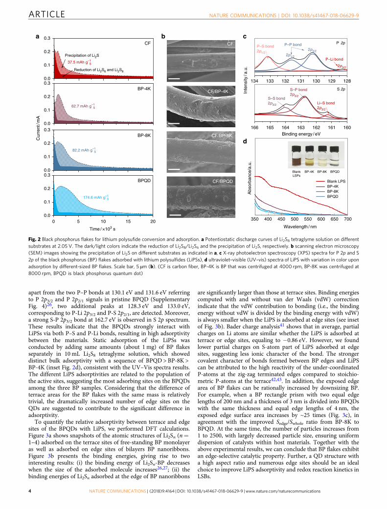
apart from the two P–P bonds at 130.1 eV and 131.6 eV referringto P 2p3/2 and P 2p2/1 signals in pristine BPQD (SupplementaryFig. 4)26, two additional peaks at 128.3 eV and 133.0 eV,corresponding to P-Li 2p3/2 and P-S 2p2/1, are detected. Moreover,a strong S-P 2p3/2 bond at 162.7 eV is observed in S 2p spectrum.These results indicate that the BPQDs strongly interact withLiPSs via both P–S and P-Li bonds, resulting in high adsorptivitybetween the materials. Static adsorption of the LiPSs wasconducted by adding same amounts (about 1 mg) of BP flakesseparately in 10 mL Li2S8 tetraglyme solution, which showeddistinct bulk adsorptivity with a sequence of BPQD > BP-8K >BP-4K (inset Fig. 2d), consistent with the UV–Vis spectra results.The different LiPS adsorptivities are related to the population ofthe active sites, suggesting the most adsorbing sites on the BPQDsamong the three BP samples. Considering that the difference ofterrace areas for the BP flakes with the same mass is relativelytrivial, the dramatically increased number of edge sites on theQDs are suggested to contribute to the significant difference inadsorptivity.
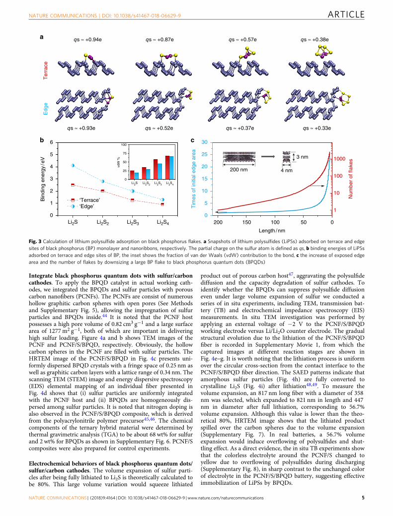
To quantify the relative adsorptivity between terrace and edgesites of the BPQDs with LiPS, we performed DFT calculations.Figure 3a shows snapshots of the atomic structures of Li2Sn (n=1–4) adsorbed on the terrace sites of free-standing BP monolayeras well as adsorbed on edge sites of bilayers BP nanoribbons.Figure 3b presents the binding energies, giving rise to twointeresting results: (i) the binding energy of Li2Sn-BP decreaseswhen the size of the adsorbed molecule increases26,27; (ii) thebinding energies of Li2Sn adsorbed at the edge of BP nanoribbons
are significantly larger than those at terrace sites. Binding energiescomputed with and without van der Waals (vdW) correctionindicate that the vdW contribution to bonding (i.e., the bindingenergy without vdW is divided by the binding energy with vdW)is always smaller when the LiPS is adsorbed at edge sites (see insetof Fig. 3b). Bader charge analysis41 shows that in average, partialcharges on Li atoms are similar whether the LiPS is adsorbed atterrace or edge sites, equaling to −0.86 eV. However, we foundlower partial charges on S-atom part of LiPS adsorbed at edgesites, suggesting less ionic character of the bond. The strongercovalent character of bonds formed between BP edges and LiPScan be attributed to the high reactivity of the under-coordinatedP-atoms at the zig-zag terminated edges compared to stoichio-metric P-atoms at the terrace42,43. In addition, the exposed edgearea of BP flakes can be rationally increased by downsizing BP.For example, when a BP rectangle prism with two equal edgelengths of 200 nm and a thickness of 3 nm is divided into BPQDswith the same thickness and equal edge lengths of 4 nm, theexposed edge surface area increases by ~25 times (Fig. 3c), inagreement with the improved Sedge/Swhole ratio from BP-8K toBPQD. At the same time, the number of particles increases from1 to 2500, with largely decreased particle size, ensuring uniformdispersion of catalysts within host materials. Together with theabove experimental results, we can conclude that BP flakes exhibitan edge-selective catalytic property. Further, a QD structure witha high aspect ratio and numerous edge sites should be an idealchoice to improve LiPS adsorptivity and redox reaction kinetics inLSBs.
00.0
0.1
0.2
0.3BPQD
174.6 mAh g–1S
0.0
0.1
0.2
0.3BP-4K
62.7 mAh g–1S
350
Blank LPSBP-4KBP-8KBPQD
Abs
orba
nce/
a.u.
Wavelength / nm
BP-4K
0.0
0.1
0.2
0.3
Precipitation of Li2S
37.5 mAh g–1S
Reduction of Li2S6 and Li2S8
CFC
urre
nt/m
A
Time / ×103 s
c
d
a
0.0
0.1
0.2
0.3BP-8K
82.2 mAh g–1S
bCF
CF/BP-4K
CF/BP-8K
CF/BPQD
166
S 2p
S–S bond2p3/2
S–P bond2p3/2
Li–S bond2p3/2
134
2p3/2
P 2pP–S bond2p1/2
2p1/2
P–P bond
2p3/2
P–Li bond
Binding energy / eV
Inte
nsity
/a.u
.
700650600550500450400
BlankLSPs
BPQDBP-8K
133 132 131 130 129 128
165 164 163 162 161 160
5 10 15 20
Fig. 2 Black phosphorus flakes for lithium polysufide conversion and adsorption. a Potentiostatic discharge curves of Li2S8 tetraglyme solution on differentsubstrates at 2.05 V. The dark/light colors indicate the reduction of Li2S8/Li2S6 and the precipitation of Li2S, respectively. b scanning electron microscopy(SEM) images showing the precipitation of Li2S on different substrates as indicated in a, c X-ray photoelectron spectroscopy (XPS) spectra for P 2p and S2p of the black phosphorus (BP) flakes adsorbed with lithium polysulfides (LiPSs), d ultraviolet–visible (UV–vis) spectra of LiPS with variation in color uponadsorption by different-sized BP flakes. Scale bar, 5 µm (b). (CF is carbon fiber, BP-4K is BP that was centrifuged at 4000 rpm, BP-8K was centrifuged at8000 rpm, BPQD is black phosphorus quantum dot)
ARTICLE NATURE COMMUNICATIONS | DOI: 10.1038/s41467-018-06629-9
4 NATURE COMMUNICATIONS | (2018) 9:4164 | DOI: 10.1038/s41467-018-06629-9 | www.nature.com/naturecommunications
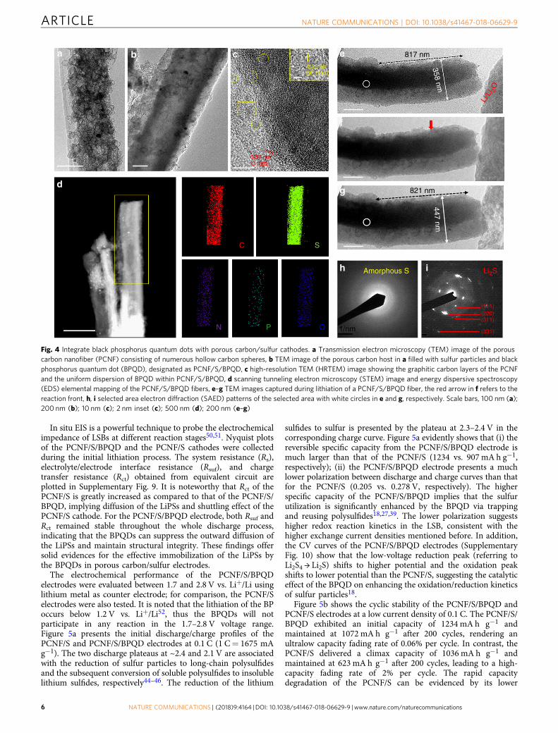
Integrate black phosphorus quantum dots with sulfur/carboncathodes. To apply the BPQD catalyst in actual working cath-odes, we integrated the BPQDs and sulfur particles with porouscarbon nanofibers (PCNFs). The PCNFs are consist of numeroushollow graphitic carbon spheres with open pores (See Methodsand Supplementary Fig. 5), allowing the impregnation of sulfurparticles and BPQDs inside.44 It is noted that the PCNF hostpossesses a high pore volume of 0.82 cm3 g−1 and a large surfacearea of 1277 m2 g−1, both of which are important in deliveringhigh sulfur loading. Figure 4a and b shows TEM images of thePCNF and PCNF/S/BPQD, respectively. Obviously, the hollowcarbon spheres in the PCNF are filled with sulfur particles. TheHRTEM image of the PCNF/S/BPQD in Fig. 4c presents uni-formly dispersed BPQD crystals with a fringe space of 0.25 nm aswell as graphitic carbon layers with a lattice range of 0.34 nm. Thescanning TEM (STEM) image and energy dispersive spectroscopy(EDS) elemental mapping of an individual fiber presented inFig. 4d shows that (i) sulfur particles are uniformly integratedwith the PCNF host and (ii) BPQDs are homogeneously dis-persed among sulfur particles. It is noted that nitrogen doping isalso observed in the PCNF/S/BPQD composite, which is derivedfrom the polyacrylonitrile polymer precursor45,46. The chemicalcomponents of the ternary hybrid material were determined bythermal gravimetric analysis (TGA) to be about 68 wt% for sulfurand 2 wt% for BPQDs as shown in Supplementary Fig. 6. PCNF/Scomposites were also prepared for control experiments.
Electrochemical behaviors of black phosphorus quantum dots/sulfur/carbon cathodes. The volume expansion of sulfur parti-cles after being fully lithiated to Li2S is theoretically calculated tobe 80%. This large volume variation would squeeze lithiated
product out of porous carbon host47, aggravating the polysulfidediffusion and the capacity degradation of sulfur cathodes. Toidentify whether the BPQDs can suppress polysulfide diffusioneven under large volume expansion of sulfur we conducted aseries of in situ experiments, including TEM, transmission bat-tery (TB) and electrochemical impedance spectroscopy (EIS)measurements. In situ TEM investigation was performed byapplying an external voltage of −2 V to the PCNF/S/BPQDworking electrode versus Li/Li2O counter electrode. The gradualstructural evolution due to the lithiation of the PCNF/S/BPQDfiber is recorded in Supplementary Movie 1, from which thecaptured images at different reaction stages are shown inFig. 4e–g. It is worth noting that the lithiation process is uniformover the circular cross-section from the contact interface to thePCNF/S/BPQD fiber direction. The SAED patterns indicate thatamorphous sulfur particles (Fig. 4h) are fully converted tocrystalline Li2S (Fig. 4i) after lithiation48,49. To measure thevolume expansion, an 817 nm long fiber with a diameter of 358nm was selected, which expanded to 821 nm in length and 447nm in diameter after full lithiation, corresponding to 56.7%volume expansion. Although this value is lower than the theo-retical 80%, HRTEM image shows that the lithiated productspilled over the carbon spheres due to the volume expansion(Supplementary Fig. 7). In real batteries, a 56.7% volumeexpansion would induce overflowing of polysulfides and shut-tling effect. As a direct evidence, the in situ TB experiments showthat the colorless electrolyte around the PCNF/S changed toyellow due to overflowing of polysulfides during discharging(Supplementary Fig. 8), in sharp contrast to the unchanged colorof electrolyte in the PCNF/S/BPQD battery, suggesting effectiveimmobilization of LiPSs by BPQDs.
2000
5
10
15
20
25
30
Tim
es o
f ini
tial e
dge
area
Length /nm
1
10
100
1000
Num
ber
of fl
akes
0
1
2
3
4
5
6
0
25
50
75
100
vdW
%
Li2S Li2S2 Li2S3 Li2S4
‘Terrace’‘Edge’
Bin
ding
ene
rgy
/eV
Li2S Li2S2 Li2S3 Li2S4
Ter
race
Edg
e
a
b c
200 nm 4 nm
3 nm
150 100 50 0
qs ≈ +0.94e
qs ≈ +0.93e qs ≈ +0.52e qs ≈ +0.37e qs ≈ +0.33e
qs ≈ +0.87e qs ≈ +0.57e qs ≈ +0.38e
Fig. 3 Calculation of lithium polysulfide adsorption on black phosphorus flakes. a Snapshots of lithium polysulfides (LiPSs) adsorbed on terrace and edgesites of black phosphorus (BP) monolayer and nanoribbons, respectively. The partial charge on the sulfur atom is defined as qs, b binding energies of LiPSsadsorbed on terrace and edge sites of BP, the inset shows the fraction of van der Waals (vdW) contribution to the bond, c the increase of exposed edgearea and the number of flakes by downsizing a large BP flake to black phosphorus quantum dots (BPQDs)
NATURE COMMUNICATIONS | DOI: 10.1038/s41467-018-06629-9 ARTICLE
NATURE COMMUNICATIONS | (2018) 9:4164 | DOI: 10.1038/s41467-018-06629-9 | www.nature.com/naturecommunications 5
In situ EIS is a powerful technique to probe the electrochemicalimpedance of LSBs at different reaction stages50,51. Nyquist plotsof the PCNF/S/BPQD and the PCNF/S cathodes were collectedduring the initial lithiation process. The system resistance (Rs),electrolyte/electrode interface resistance (Rsuf), and chargetransfer resistance (Rct) obtained from equivalent circuit areplotted in Supplementary Fig. 9. It is noteworthy that Rct of thePCNF/S is greatly increased as compared to that of the PCNF/S/BPQD, implying diffusion of the LiPSs and shuttling effect of thePCNF/S cathode. For the PCNF/S/BPQD electrode, both Rsuf andRct remained stable throughout the whole discharge process,indicating that the BPQDs can suppress the outward diffusion ofthe LiPSs and maintain structural integrity. These findings offersolid evidences for the effective immobilization of the LiPSs bythe BPQDs in porous carbon/sulfur electrodes.
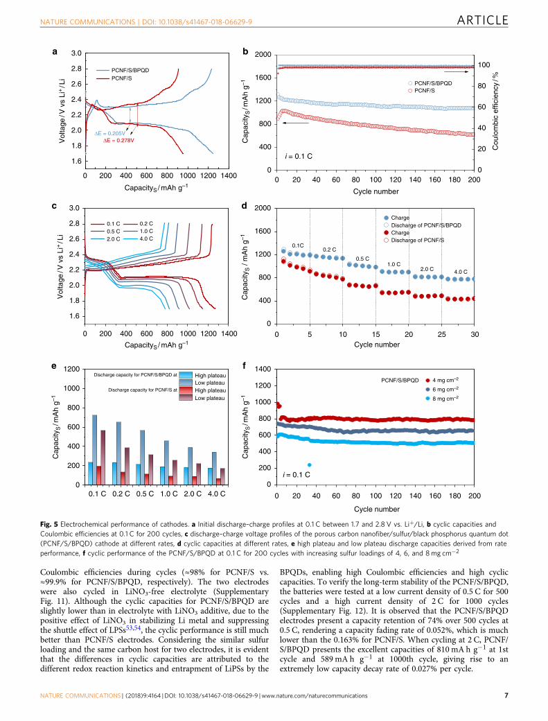
The electrochemical performance of the PCNF/S/BPQDelectrodes were evaluated between 1.7 and 2.8 V vs. Li+/Li usinglithium metal as counter electrode; for comparison, the PCNF/Selectrodes were also tested. It is noted that the lithiation of the BPoccurs below 1.2 V vs. Li+/Li52, thus the BPQDs will notparticipate in any reaction in the 1.7–2.8 V voltage range.Figure 5a presents the initial discharge/charge profiles of thePCNF/S and PCNF/S/BPQD electrodes at 0.1 C (1 C= 1675 mAg−1). The two discharge plateaus at ~2.4 and 2.1 V are associatedwith the reduction of sulfur particles to long-chain polysulfidesand the subsequent conversion of soluble polysulfides to insolublelithium sulfides, respectively44–46. The reduction of the lithium
sulfides to sulfur is presented by the plateau at 2.3–2.4 V in thecorresponding charge curve. Figure 5a evidently shows that (i) thereversible specific capacity from the PCNF/S/BPQD electrode ismuch larger than that of the PCNF/S (1234 vs. 907 mA h g−1,respectively); (ii) the PCNF/S/BPQD electrode presents a muchlower polarization between discharge and charge curves than thatfor the PCNF/S (0.205 vs. 0.278 V, respectively). The higherspecific capacity of the PCNF/S/BPQD implies that the sulfurutilization is significantly enhanced by the BPQD via trappingand reusing polysulfides18,27,39. The lower polarization suggestshigher redox reaction kinetics in the LSB, consistent with thehigher exchange current densities mentioned before. In addition,the CV curves of the PCNF/S/BPQD electrodes (SupplementaryFig. 10) show that the low-voltage reduction peak (referring toLi2S4 → Li2S) shifts to higher potential and the oxidation peakshifts to lower potential than the PCNF/S, suggesting the catalyticeffect of the BPQD on enhancing the oxidation/reduction kineticsof sulfur particles18.
Figure 5b shows the cyclic stability of the PCNF/S/BPQD andPCNF/S electrodes at a low current density of 0.1 C. The PCNF/S/BPQD exhibited an initial capacity of 1234 mA h g−1 andmaintained at 1072 mA h g−1 after 200 cycles, rendering anultralow capacity fading rate of 0.06% per cycle. In contrast, thePCNF/S delivered a climax capacity of 1036 mA h g−1 andmaintained at 623 mA h g−1 after 200 cycles, leading to a high-capacity fading rate of 2% per cycle. The rapid capacitydegradation of the PCNF/S can be evidenced by its lower
a b e
f
g
h
d
N
C
0.25 nmBP (111)
0.34 nmC (002)
817 nm
821 nm
Amorphous S Li2S
(111)
(311)
(331)
(220)
447 nm
Li/L
i 2O
358 nm
P
S
O
c
i
1/nm
Fig. 4 Integrate black phosphorus quantum dots with porous carbon/sulfur cathodes. a Transmission electron microscopy (TEM) image of the porouscarbon nanofiber (PCNF) consisting of numerous hollow carbon spheres, b TEM image of the porous carbon host in a filled with sulfur particles and blackphosphorus quantum dot (BPQD), designated as PCNF/S/BPQD, c high-resolution TEM (HRTEM) image showing the graphitic carbon layers of the PCNFand the uniform dispersion of BPQD within PCNF/S/BPQD, d scanning tunneling electron microscopy (STEM) image and energy dispersive spectroscopy(EDS) elemental mapping of the PCNF/S/BPQD fibers, e–g TEM images captured during lithiation of a PCNF/S/BPQD fiber, the red arrow in f refers to thereaction front, h, i selected area electron diffraction (SAED) patterns of the selected area with white circles in e and g, respectively. Scale bars, 100 nm (a);200 nm (b); 10 nm (c); 2 nm inset (c); 500 nm (d); 200 nm (e–g)
ARTICLE NATURE COMMUNICATIONS | DOI: 10.1038/s41467-018-06629-9
6 NATURE COMMUNICATIONS | (2018) 9:4164 | DOI: 10.1038/s41467-018-06629-9 | www.nature.com/naturecommunications
Coulombic efficiencies during cycles (≈98% for PCNF/S vs.≈99.9% for PCNF/S/BPQD, respectively). The two electrodeswere also cycled in LiNO3-free electrolyte (SupplementaryFig. 11). Although the cyclic capacities for PCNF/S/BPQD areslightly lower than in electrolyte with LiNO3 additive, due to thepositive effect of LiNO3 in stabilizing Li metal and suppressingthe shuttle effect of LPSs53,54, the cyclic performance is still muchbetter than PCNF/S electrodes. Considering the similar sulfurloading and the same carbon host for two electrodes, it is evidentthat the differences in cyclic capacities are attributed to thedifferent redox reaction kinetics and entrapment of LiPSs by the
BPQDs, enabling high Coulombic efficiencies and high cycliccapacities. To verify the long-term stability of the PCNF/S/BPQD,the batteries were tested at a low current density of 0.5 C for 500cycles and a high current density of 2 C for 1000 cycles(Supplementary Fig. 12). It is observed that the PCNF/S/BPQDelectrodes present a capacity retention of 74% over 500 cycles at0.5 C, rendering a capacity fading rate of 0.052%, which is muchlower than the 0.163% for PCNF/S. When cycling at 2 C, PCNF/S/BPQD presents the excellent capacities of 810 mA h g−1 at 1stcycle and 589mA h g−1 at 1000th cycle, giving rise to anextremely low capacity decay rate of 0.027% per cycle.
0
1.6
1.8
2.0
2.2
2.4
2.6
2.8
3.0
ΔE = 0.205V
PCNF/S/BPQDPCNF/S
Vol
tage
/V v
s Li
+/L
i
CapacityS / mAh g–1
Cap
acity
S /
mA
h g–1
Cap
acity
S/m
Ah
g–1
Cap
acity
S/m
Ah
g–1
ΔE = 0.278V
1.6
1.8
2.0
2.2
2.4
2.6
2.8
3.0
0.1 C 0.2 C0.5 C 1.0 C2.0 C 4.0 C
Vol
tage
/V v
s Li
+/L
i
0
200
400
600
800
1000
1200
1400
4 mg cm–2
6 mg cm–2
8 mg cm–2
Cycle number
i = 0.1 C
PCNF/S/BPQD
a b
c d
fe
0
200
400
600
800
1000
1200Discharge capacity for PCNF/S/BPQD at High plateau
Low plateauDischarge capacity for PCNF/S at High plateau
Low plateau
0.1 C 0.2 C 0.5 C 1.0 C 2.0 C 4.0 C
0
0
400
800
1200
1600
2000ChargeDischarge of PCNF/S/BPQDChargeDischarge of PCNF/S
Cycle number
0.1C0.2 C
0.5 C1.0 C
2.0 C 4.0 C
0
400
800
1200
1600
2000
PCNF/S/BPQDPCNF/S
Cap
acity
S/m
Ah
g–1
Cycle number
i = 0.1 C
0
20
40
60
80
100
Cou
lom
bic
effic
ienc
y/%
200 400 140012001000800600
0
CapacityS / mAh g–1
200 400 140012001000800600
0 20 40 140 160 180 2001201008060
0 20 40 140 160 180 2001201008060
5 10 15 20 25 30
Fig. 5 Electrochemical performance of cathodes. a Initial discharge–charge profiles at 0.1 C between 1.7 and 2.8 V vs. Li+/Li, b cyclic capacities andCoulombic efficiencies at 0.1 C for 200 cycles, c discharge–charge voltage profiles of the porous carbon nanofiber/sulfur/black phosphorus quantum dot(PCNF/S/BPQD) cathode at different rates, d cyclic capacities at different rates, e high plateau and low plateau discharge capacities derived from rateperformance, f cyclic performance of the PCNF/S/BPQD at 0.1 C for 200 cycles with increasing sulfur loadings of 4, 6, and 8mg cm−2
NATURE COMMUNICATIONS | DOI: 10.1038/s41467-018-06629-9 ARTICLE
NATURE COMMUNICATIONS | (2018) 9:4164 | DOI: 10.1038/s41467-018-06629-9 | www.nature.com/naturecommunications 7
The catalytic effect of the BPQDs can be more clearly evaluatedby cycling batteries at high rates, which require faster chargetransfer and higher redox reaction kinetics at the electrode/electrolyte interface. The PCNF/S/BPQD exhibits reversiblecapacities of 1266, 1172, 1030, 910, 821, and 784 mA h g−1 at0.1, 0.2, 0.5, 1, 2, and 4 C, respectively (Fig. 5c). Both thedischarge and charge curves overlap well below the currentdensity of 1 C, suggesting excellent kinetics and small polariza-tions of the PCNF/S/BPQD electrodes. The apparent platformsare still maintained even at high rates above 1 C, which can beattributed to the firm chemical interactions between LiPSs andBPQD and the facilitated conversion reactions. The decreasedcapacity and increased polarization for the PCNF/S/BPQD maybe ascribed to the high ohmic resistance at higher currentdensities55,56. In contrast, the PCNF/S displays much lowercapacities (Fig. 5d) under the same rate cycling conditions. Toelucidate reasons for the difference, we separated out the highplateau (at about 2.35 V, referring to generation of polysulfides)and the low plateau (at about 2.1 V, referring to nucleation/growth of lithium sulfides) discharge contributions to the totalcapacities at different current rates for the PCNF/S/BPQD andPCNF/S electrodes (Fig. 5c and Supplementary Fig. 10). The highplateau capacity for PCNF/S/BPQD decreases by ca. 25% (from232 to 173 mA h g−1) with current density increasing from 0.1 to4 C (Fig. 5e), which is much lower than ca. 67 % (from 191 to 63mA h g−1) for PCNF/S, confirming the strong immobilization ofLiPSs by BPQD in the PCNF/S/BPQD electrode. We also findthat the low plateau discharge capacity at 4 C for the PCNF/S/BPQD maintains 47% of the capacity at 0.1 C, greater than the30% for the PCNF/S electrodes. The high discharge capacityretention at low plateau indicates the facilitated conversionreactions catalyzed by the BPQD in PCNF/S/BPQD electrodes. Inaddition, Supplementary Fig. 10 shows the high and lowdischarge plateau voltages of PCNF/S and PCNF/S/BPQDelectrodes at different C-rates. In contrast to the sharp decreaseof low discharge plateau voltage for PCNF/S at high rate (i.e.,from 2.12 V at 0.1 C to 1.76 V at 4 C), the PCNF/S/BPQD systemdisplays much better performance (i.e., from 2.11 V at 0.1 C to1.99 V at 4 C), indicating the low polarization and fast redoxreaction from the catalytic effect of BPQD in LSBs27. As a finalpiece of evidence, the PCNF/S/BPQD electrodes exhibit cycliccapacity retentions of 95%, 90%, and 89% after 200 cycles at 0.1 Cat high areal sulfur loadings of 4, 6, and 8 mg cm−2 (Fig. 5f),respectively. The impressive stability at high sulfur loadingssuggests that the BPQDs can effectively immobilize floodedpolysulfides of thick electrodes. It is noteworthy that the 89%capacity retention for PCNF/S/BPQD cycled under an electrolyte/sulfur (E/S) ratio of 6.5 mL g−1 for 200 cycles is competitive to thestate-of-the-art LSBs with low E/S ratios10,57. It is believed thatbetter performance under lean electrolyte conditions can beachieved by combining our findings of using BPQD catalysts andoptimizations in other components of LSBs58,59. Overall, theexcellent electrochemical performance of the PCNF/S/BPQDdemonstrates that the BPQDs are highly effective in improvingLSB performance with sulfur/carbon cathodes.
DiscussionWe have demonstrated the catalytic effect of the BPQDs forefficient trapping and conversion of LiPSs via a suite of experi-mental and theoretical studies. To identify the superiority ofBPQDs to other reported catalysts for LSBs, we have comparedthe physicochemical properties and their corresponding electro-chemical performance in LSBs in Supplementary Table 1 andTable 2. The unique advantages of the BPQD catalyst for LSBscan be summarized as following: (i) the BPQD as a metal-free
catalyst holds the lowest gravimetric density among reportedcatalysts (Supplementary Table 1) to the best of our knowledge,thus for the same weight fraction of catalyst, the active surfacearea will far exceed that of metals (Pt, Ni)39,40, metal oxide phases(Fe2O3, MnO2)60,61 and metal nitride materials (VN, TiN)56,62.(ii) The BPQDs with unique edge-preferential LiPS immobiliza-tion ability offer more active sites than routine 2D structures. TheQD structure with exposed edge sites outperforms bulk flakesbased on the amount of active sites, thus leading to better elec-trochemical performance. For example, both WS2 and MoS2flakes exhibited an edge-selective catalytic property for LiPSs;however, the reported rate capacities (~400 mA h g−1 at 2 C forMoS2/CNF/Li2S8 and 380 mA h g−1 at 1 C for WS2/Li2S6)30 aremuch lower than the current BPQD modified cathode (784 mA hg−1 at 4 C). (iii) The BPQD with few-layer thickness is expectedto possess high electrical conductivity27, which is higher thanthose for metal oxides60,61 and metal carbides36, thus ensuringrapid conversion kinetics for trapped LiPS to Li2S particles. Inaddition, the physical confinement from the PCNF host alsocontributes to the excellent electrochemical performance. Post-cycled analysis reveals that the overall morphology of the PCNF/S/BPQD composite was almost intact (Supplementary Fig. 13),indicating the robust structural stability of PCNF host. HRTEMimages and elemental mappings show that BPQD crystals andsulfur particles are uniformly confined within the fibers, sug-gesting the chemical and structural integrity of PCNF/S/BPQDduring cycling. Consequently, our PCNF/S/BPQD cathodesexhibit one of the best electrochemical performances amongreported catalyst-modified cathodes in terms of cyclic capacities,high-rate capability, and areal capacities at high sulfur loadings(Supplementary Table 2). PCNF/S/BPQD electrodes with a highsulfur loading of 8 mg cm−2 and a low E/S ratio of ~6.5 mL g−1
delivered an area capacity of 4.4 mA h cm−2 after 200 cycles,which is higher than the 4.0 mA h cm−2 for commercial LiCoO2
cathodes57. It is worth noting that high sulfur loading and low E/Sratio are recently considered critical challenges for fabricatingpractical LSBs to outperform commercial LIBs10. We believe thatincorporating our highly effective BPQD catalyst with highlyconcentrated polysulfide catholyte would be a promising strategyto mitigate these issues (Supplementary Fig. 14). Moreover,thanks to the high yield of the top-down synthetic procedure27 aswell as the low content (2 wt%) needed to boost the LSB per-formance, the large scale application of BPQDs in LSBs is notproblematic.
In summary, we demonstrated the effectiveness of the BPQDsas a catalyst for polysulfide immobilization and conversion inLSBs. By downsizing the particle size of 2D BP flakes, we foundthat the BPQDs exhibited higher LiPS adsorptivity and larger Li2Sprecipitation capacity than the large BP flakes. DFT calculationsrevealed that the edge sites of the 2D BP materials showed pre-ferential adsorption of polysulfides, inducing more catalyticallyactive sites than bulk BP flakes, thus dictating the superior cat-alytic performance of the BPQD. To apply the BPQD in actualcathodes, a small amount of the BPQD was integrated withporous carbon/sulfur composite. Time-sequence TEM imagesshowed a large volume expansion and overflowing of reactionproducts of the PCNF/S/BPQD fiber during lithiation, however,there was neither diffusion of yellow LiPS in a transparent batterynor an increase in battery impedance for the PCNF/S/BPQDelectrodes in EIS measurements, thus demonstrating the effec-tiveness of the BPQD in immobilizing LiPSs. As a result, thePCNF/S/BPQD electrode exhibited impressive electrochemicalperformance, including a reversible capacity of 1072 mA h g−1
after 200 deep discharge/charge cycles at 0.1 C, a high-ratecapacity of 784 mA h g−1 at 4 C and remarkable capacity reten-tion of near 90% at high sulfur loadings up to 8 mg cm−2. We
ARTICLE NATURE COMMUNICATIONS | DOI: 10.1038/s41467-018-06629-9
8 NATURE COMMUNICATIONS | (2018) 9:4164 | DOI: 10.1038/s41467-018-06629-9 | www.nature.com/naturecommunications
believe that these findings open a new avenue toward the designof high energy rechargeable batteries through the exploration ofmetal-free catalyst materials.
MethodsMaterials preparation. For BPQD preparation, BP crystal was purchased fromSmart Elements. We added 45 mg BP crystals into 20 mL NMP solution and ultra-sonicated using an ultrasonic bath (400W) at a temperature of 20 °C through thewhole experiment for 8.0 h. The obtained BP solution was purified by cen-trifugation, with rates of 1000–3000 rpm for 30 min, to remove large particles atbottom. Then the BP suspension was further sonicated using probe sonication. Theas-obtained BP/NMP solution was centrifuged at 4000, 8000, and 12,000 rpm for30 min, and the precipitates were collected and designated as BP-4K, BP-8K, andBPQD, respectively. The yield of BPQD produced in this work is discussed inSupplementary Note 1. The as-obtained BP NMP solutions were stored in an Ar-filled glove box to ensure their stability. Without mention, all below experimentsrelated to BP flakes were conducted in the glove box.
For porous carbon nanofiber synthesis, 0.5 g polyacrylonitrile was dissolved in20 ml N,N-dimethylformamide solvent and magnetically stirred for 8 h at 80 °C.Then, 1.0 g iron (III) acethylacetonate was added to the above solution and stirredfor another 8 h. The polymer mixture was electrospun into nanofibers using anelectrospiner at 18 kV with a constant flow rate of 1 mL h−1. The neat fibers werestabilized in air for 3 h at 220 °C and sequentially carbonized in Ar atmosphere for1 h at 650 °C at a ramp rate of 3 °C min−1. The resultant carbon nanofiberscontaining Fe3C particles were soaked in fuming HNO3 for 10 h to create hollowgraphitic carbon spheres via removing the Fe3C catalyst. To open the graphiticcarbon walls, the as-obtained porous carbon nanofibers were mixed with KOH at amass ratio of 1:4 and transferred to a tube furnace and heated at 750 °C for 0.5 hunder Ar gas flow. Then the resulting product was washed with flooded amount ofHCl (0.1 M) and DI water subsequently, before drying in vacuum oven for 8 h at100 °C.
For PCNF/S composite preparation, the PCNF was mixed with sulfur particlesat a mass ratio of 25:75. The PCNF/S mixture was then placed in a tube furnacewith Ar flow and heated at 155 °C for 12 h to infiltrate molten sulfur within PCNFhost. The PCNF/S/BPQD composites were prepared by adding about 3 wt% BPQDin PCNF/S composite in CS2 solution. CS2 can dissolve sulfur particles thus theBPQD and sulfur would be simultaneously re-infiltrated into PCNF host bycapillary force. It is worth noting that the morphology and stability of BPQD wouldnot be affected by CS2 solvent (Supplementary Fig. 15).
Materials characterization. For structural characterization of BP, Raman spectrawere obtained from a Horiba Jobin Yvon HR800 Raman microscopic systemequipped with a 488 nm laser operating at 180 mW. The spot size of Raman laserwas controlled near 1 µm. A TEM (JEOL 2100F) working at 200 kV was used toestimate the morphological information of BP flakes and BPQD.
For PCNF and PCNF/S/BPQD characterization, the morphologies wereinvestigated using a SEM (JEOL 6700) and a TEM. The STEM image and elementalmapping of PCNF/S/BPQD were conducted on the JEOL 2100-TEM equipped withEDS detector. The surface area and pore size distribution of PCNF host weredetermined from N2 adsorption/desorption isotherms at 77 K using an automatedadsorption apparatus (Micromeritics, ASAP 2020). The chemical compositions ofsulfur/carbon composites were evaluated by TGA (Q5000) at a ramp rate of 5.0 °Cmin−1 in nitrogen atmosphere.
Adsorption and catalytic studies of black phosphorus quantum dots. Li2S8solution was prepared by mixing sulfur particles and Li2S with a molar ratio of 7:1in tetraglyme solvent, followed by stirring at 50 °C for 8 h in an Ar-filled glove box.1 mg of BP-4K, BP-8K, and PBQD powders were dispersed individually in 10 mLLi2S8/tetraglyme solution with a concentration of 5 mmol L−1 in sulfur. To observethe color change, the mixtures were kept standing for 12 h. The supernatant andthe BP precipitates of the mixtures were studied by UV–vis spectrophotometry andXPS, respectively. The precipitates were obtained by centrifugation.
The nucleation and growth of Li2S from soluble polysulfides were studied bypotentiostatic deposition of Li2S8 tetraglyme solution (0.2 mol L−1 based on sulfur)on CF-based current collectors. CF papers were punched into disks with a diameterof 14 mm and about 0.40 mg of BP-4K, BP-8K, and BPQD powders were separatelydispersed on CF papers using pure ethanol as solvent. 25 µL Li2S8 was droppedonto the CF/BP current collectors as cathode. Lithium foil was employed at thecounter electrode, which was separated with cathode by Celgard 2400 membraneand dropped with 25 µL 0.50 mol L−1 lithium bis(trifluoromethanesulfonyl)imide(LiTFSI) tetraglyme electrolyte on the Li metal side. The cells were galvanostaticallydischarged to 2.06 V at a constant current density of 0.112 mA, and then keptpotentiostatically at 2.05 V for Li2S to nucleate and grow until the current droppedbelow 10−5 A. It took about 60,000 s and the energy was integrated to evaluate thecapacities from deposition of lithium sulfide on various surfaces according toFaraday’s law.
The catalytic property of the BPQDs was further studied by CV test ofsymmetric cells. The CF/BPQD and CF symmetric cells were prepared byassembling identical electrodes with a Celgard 2400 membrane as separator, and
25 µL Li2S4 (0.2 mol L−1) tetraglyme electrolyte was added. CV was performance atCHI 660c electrochemical workstation at a scan rate of 1 mV s−1 between −1.0 and1.0 V. LSV studies were conducted using CF/BPQD or CF as working electrode,lithium foil as counter electrode and 0.2 mol L−1 Li2S4 as catholyte. The cells weretested at electrochemical workstation between 1.7 and 2.8 V at a scan rate of 0.1mV s−1.
In situ characterization. In situ TEM experiment was conducted on a JEOL 2100-TEM equipped with a Nanofactory scanning tunneling microscope (STM) holder.A thin layer of Li metal was scratched on the tip of a sharp Cu rode as referenceelectrode, while PCNF/S/BPQD fibers were dispersed on the tip of another Cu wireas working electrode. During the transfer of the STM holder assembled with twoelectrodes in TEM chamber, Ar gas flow was used to protect Li metal frommoisture and oxygen. A potential of −2.0 V vs. Li/Li2O was applied to workingelectrode to drive the lithiation reaction once a physical contact is confirmedbetween two electrodes. In situ TB experiment was conducted by sealing a PCNF/S/BPQD or PCNF/S cathode and a Li metal anode in a glass bottle filled with about12.0 mL 1.0 mol L−1 LiTFSI 1,3-dioxolane: 1,2-dimethoxy (DOL: DME, 1/1 v/v)electrolyte. The transparent batteries were galvanostatically discharged at 0.10 mAfor 8 h, when optical images were taken to show the color change of electrolyte. Insitu EIS measurements were performed on a Bio-Logic VSP-300 analyzer. The cellswere assembled using PCNF/S/BPQD or PCNF/S cathodes and Li metal anodes inan Ar-filled glove box, to be discussed below. After every 20 min galvanostaticdischarge at 0.1 C, we held the cells for 15 min to reach equilibrium before per-forming the EIS measurement. The EIS was conducted at a perturbation amplitudeof 5 mV in the frequency between 10 mHz and 100 kHz. The EIS spectra weresimulated using Z-view software.
Cell assembly and electrochemical performance. To measure of the electro-chemical performance, the cathodes were prepared by mixing PCNF/S/BPQDcomposite, carbon black, and polyvinylidene fluoride binder at a mass ratio of 8:1:1using NMP solvent. The slurry mixture was cast on aluminum foil and cut intodiscs (ɸ= 14 mm), giving rise to an average sulfur loading of about 2 mg cm−2.The cathodes were assembled into CR2032 coin cells using Li metal anode,1 mol L−1 LiTFSI DOL/DME electrolyte with 1.0 wt% LiNO3 additive, and poly-ethylene membrane (Celgard 2400) separator in an Ar-filled glove box. The elec-trolyte added in the cell is 80 µL, and the electrolyte/sulfur ratios are about 26,13, 8.7, and 6.5 mL g−1 for the electrodes with sulfur loadings of 2, 4, 6, and 8 mgcm−2, respectively. These values are comparable with previous reports18,19,46. ThePCNF/BPQD/catholyte electrodes were prepared by dropping 45 µL 1.5 mol L−1
Li2S6 catholyte into PCNF/BPQD electrode substrate (1 × 1 cm2, about 3 mg cm−2
with 2 wt% of BPQD). The polysulfide catholyte was prepared by mixing stoi-chiometric amount of sulfur and Li2S in DOL/DME= 1/1 v/v with 1.85 mol L−1
LiTFSI and 0.2 mol L−1 LiNO3, according to the previous work57. The final elec-trode achieved a high sulfur loading of 13.2 mg cm−2 and a sulfur content of 81 wt%. Additional blank electrolyte was used to wet separator to achieve an E/S ratio of~4 mL g−1. The cells were tested at different current densities between 1.7 and 2.8V vs. Li+/Li on a LAND 2100CT battery tester. The post-mortem analysis wascarried out by dissembling the cycled PCNF/S/BPQD electrodes in a glove box andwashing with flooded amounts of DME to remove the salt and byproducts. Cycledelectrodes were sealed in Ar-filled bottles before sending to SEM and TEMcharacterizations.
Theoretical calculations. DFT calculations were performed with the Vienna Abinitio Simulation Package (VASP)63,64, within the generalized gradient approx-imation proposed by Perdew, Burke, and Ernzerhof (PBE)65. We used Grimme’sDFT-D2 method66 to correct for the vdW interaction poorly described by standardDFT. We studied the energetics of adsorbed LiPSs on two types of BP structures:2D-free-standing monolayer and one-dimensional bilayers zig-zag terminated BPnanoribbons, as represented in Supplementary Fig. 16. It has been shown that ZZterminations are lower in energy than their arm-chair counterpart67. Therefore, weassume that all the BPQD edges are ZZ-terminated. DFT simulations were per-formed with a kinetic energy cutoff of 500 eV and we used two k-points in theperiodic directions to evaluate the integrals in the reciprocal space. Convergencewas achieved when energy, force and stress reached a minimum of 5 × 10⁻⁴ eV,5 × 10−2 eV Å−1, and 5 × 10⁻² GPa, respectively. The potential energy surfacecorresponding to the adsorption of LiPS at the terrace or at the edge of BP is roughand presents multiple minima. Therefore, to find the lowest energy location ofadsorbed LiPS on BP, we performed for each compound, ab initio moleculardynamics simulations at 300 K with a kinetic energy cutoff of 300 eV and a timestep of 1.5 fs. Finally, we computed the binding energy Eb as:
Eb ¼ ELiPS þ EBP � ELiPS@BP ð1Þ
with ELiPS, EBP, and ELiPS@BP the energy of LiPSs, BP, and LiPSs adsorbed on theterrace site (or at the edge site) of BP, respectively. Following this definition, higherbinding energy implies more favorable adsorption.
NATURE COMMUNICATIONS | DOI: 10.1038/s41467-018-06629-9 ARTICLE
NATURE COMMUNICATIONS | (2018) 9:4164 | DOI: 10.1038/s41467-018-06629-9 | www.nature.com/naturecommunications 9
Data availabilityThe data that support the findings in this study are in the paper and/or the 524 Sup-plementary Information. Additional data are available from the authors upon reasonable525 request.
Received: 26 February 2018 Accepted: 14 September 2018
References1. Bruce, P. G., Freunberger, S. A., Hardwick, L. J. & Tarascon, J. M. Li–O2 and
Li–S batteries with high energy storage. Nat. Mater. 11, 19–29 (2011).2. Xu, Z. L., Liu, X., Luo, Y., Zhou, L. & Kim, J. K. Nanosilicon anodes for high
performance rechargeable batteries. Prog. Mater. Sci. 90, 1–44 (2017).3. Manthiram, A., Fu, Y. & Su, Y. Challenges and prospects of lithium-sulfur
batteries. Acc. Chem. Res. 46, 1125–1134 (2013).4. Wild, M. et al. Lithium sulfur batteries, a mechanistic review. Energy Environ.
Sci. 8, 3477–3494 (2015).5. Pang, Q., Liang, X., Kwok, C. Y. & Nazar, L. F. Advances in lithium-sulfur
batteries based on multifunctional cathodes and electrolytes. Nat. Energy 1,16132 (2016).
6. Ji, X., Lee, K. T. & Nazar, L. F. A highly ordered nanostructuredcarbon–sulphur cathode for lithium–sulphur batteries. Nat. Mater. 8, 500–506(2009).
7. Su, Y. S. & Manthiram, A. Lithium–sulphur batteries with a microporouscarbon paper as a bifunctional interlayer. Nat. Commun. 3, 1166 (2012).
8. Xin, S. et al. Smaller sulfur molecules promise better lithium-sulfur batteries. J.Am. Chem. Soc. 134, 18510–18513 (2012).
9. Chong, W. G. et al. Lithium-sulfur battery cable made from ultralight, flexiblegraphene/carbon nanotube/sulfur composite fibers. Adv. Funct. Mater. 27,1604815 (2017).
10. Xu, Z. L., Kim, J. K. & Kang, K. Carbon nanomaterials for advanced lithiumsulfur batteries. Nano Today 19, 84–107 (2018).
11. Pang, Q., Liang, X., Kwok, C. Y. & Nazar, L. F. Review—the importance ofchemical interactions between sulfur host materials and lithium polysulfidesfor advanced lithium-sulfur batteries. J. Electrochem. Soc. 162, A2567–A2576(2015).
12. Li, L. et al. Stabilizing sulfur cathodes using nitrogen-doped graphene as achemical immobilizer for Li-S batteries. Carbon N. Y. 108, 120–126(2016).
13. Gao, J. et al. Vertically oriented arrays of ReS2 nanosheets for electrochemicalenergy storage and electrocatalysis. Nano Lett. 16, 3780–3787 (2016).
14. Hou, T. Z. et al. Lithium bond chemistry in lithium-sulfur batteries. Angew.Chem. Int. Ed. 56, 8178–8182 (2017).
15. Zheng, J. et al. Lewis acid-base interactions between polysulfides and metalorganic framework in lithium sulfur batteries. Nano Lett. 14, 2345–2352(2014).
16. Tao, X. et al. Balancing surface adsorption and diffusion of lithium-polysulfides on nonconductive oxides for lithium-sulfur battery design. Nat.Commun. 7, 11203 (2016).
17. Liu, D. et al. Catalytic effects in lithium-sulfur batteries: promoted sulfurtransformation and reduced shuttle effect. Adv. Sci. 5, 1700270 (2018).
18. Zhou, T. et al. Twinborn TiO2–TiN heterostructures enabling smoothtrapping–diffusion–conversion of polysulfides towards ultralong life lithium-sulfur batteries. Energy Environ. Sci. 10, 1694–1703 (2017).
19. Yuan, Z. et al. Powering lithium-sulfur battery performance by propellingpolysulfide redox at sulfiphilic hosts. Nano Lett. 16, 519–527 (2016).
20. Lei, T. et al. Multi-functional layered WS2 nanosheets for enhancing theperformance of lithium-sulfur batteries. Adv. Energy Mater. 7, 1601843(2017).
21. Keyes, R. W. The electrical properties of black phosphorus. Phys. Rev. 92,580–584 (1953).
22. Liu, H., Du, Y., Deng, Y. & Ye, P. D. Semiconducting black phosphorus:synthesis, transport properties and electronic applications. Chem. Soc. Rev. 44,2732–2743 (2015).
23. Liu, S. et al. Black phosphorus quantum dots used for boosting lightharvesting in organic photovoltaics. Angew. Chem. Int. Ed. 56, 13717–13721(2017).
24. Li, L. et al. Black phosphorus field-effect transistors. Nat. Nanotechnol. 9,372–377 (2014).
25. Li, W., Yang, Y., Zhang, G. & Zhang, Y. W. Ultrafast and directional diffusionof lithium in phosphorene for high-performance lithium-ion battery. NanoLett. 15, 1691–1697 (2015).
26. Sun, J. et al. Entrapment of polysulfides by a black-phosphorus-modifiedseparator for lithium-sulfur batteries. Adv. Mater. 28, 9797–9803 (2016).
27. Li, L. et al. Phosphorene as a polysulfide immobilizer and catalyst in high-performance lithium-sulfur batteries. Adv. Mater. 29, 1602734 (2017).
28. Zhang, S., Ding, M. S., Xu, K., Allen, J. & Jow, T. R. Understanding solidelectrolyte interface film formation on graphite electrodes. Electrochem. Solid-State Lett. 4, A206 (2001).
29. Wang, H. et al. High electrochemical selectivity of edge versus terrace sites intwo-dimensional layered MoS2 materials. Nano Lett. 14, 7138–7144(2014).
30. Babu, G., Masurkar, N., Al Salem, H. & Arava, L. M. R. Transition metaldichalcogenide atomic layers for lithium polysulfides electrocatalysis. J. Am.Chem. Soc. 139, 171–178 (2017).
31. Hinnemann, B. et al. Biomimetic hydrogen evolution: MoS2 nanoparticles ascatalyst for hydrogen evolution. J. Am. Chem. Soc. 127, 5308–5309 (2005).
32. Zhang, X. et al. Black phosphorus quantum dots. Angew. Chem. Int. Ed. 54,3653–3657 (2015).
33. Sun, Z. et al. Ultrasmall black phosphorus quantum dots: synthesis and use asphotothermal agents. Angew. Chem. Int. Ed. 54, 11526–11530 (2015).
34. Sun, J. et al. A phosphorene–graphene hybrid material as a high-capacityanode for sodium-ion batteries. Nat. Nanotechnol. 10, 980–985 (2015).
35. Xie, J. et al. A supramolecular capsule for reversible polysulfide storage/delivery in lithium-sulfur batteries. Angew. Chem. Int. Ed. 56, 16223–16227(2017).
36. Peng, H. J. et al. Enhanced electrochemical kinetics on conductive polarmediators for lithium-sulfur batteries. Angew. Chem. Int. Ed. 55, 12990–12995(2016).
37. Fan, F. Y., Carter, W. C. & Chiang, Y. M. Mechanism and kinetics of Li2Sprecipitation in lithium-sulfur batteries. Adv. Mater. 27, 5203–5209 (2015).
38. Gerber, L. C. H. et al. Three-dimensional growth of Li2S in lithium-sulfurbatteries promoted by a redox mediator. Nano Lett. 16, 549–554 (2016).
39. Al Salem, H., Babu, G., V. Rao, C. & Arava, L. M. R. Electrocatalyticpolysulfide traps for controlling redox shuttle process of Li-S batteries. J. Am.Chem. Soc. 137, 11542–11545 (2015).
40. Babu, G., Ababtain, K., Ng, K. Y. S. & Arava, L. M. R. Electrocatalysis oflithium polysulfides: current collectors as electrodes in Li/S batteryconfiguration. Sci. Rep. 5, 8763 (2015).
41. Henkelman, G., Arnaldsson, A. & Jónsson, H. A fast and robust algorithm forBader decomposition of charge density. Comput. Mater. Sci. 36, 354–360(2006).
42. Zhao, J., Yang, Y., Katiyar, R. S. & Chen, Z. Phosphorene as a promisinganchoring material for lithium-sulfur batteries: a computational study. J.Mater. Chem. A 4, 6124–6130 (2016).
43. Jiang, Z. T., Liang, F. X. & Zhang, X. D. A comparative study on the edgestates in phosphorene quantum dots and rings. Phys. Lett. A 381, 373–378(2017).
44. Xu, Z. L. et al. In situ TEM study of volume expansion in porous carbonnanofiber/sulfur cathodes with exceptional high-rate performance. Adv.Energy Mater. 7, 1602078 (2017).
45. Huang, J. Q. et al. Novel interlayer made from Fe3C/carbon nanofiber webs forhigh performance lithium-sulfur batteries. J. Power Sources 285, 43–50 (2015).
46. Yin, L. C. et al. Understanding the interactions between lithium polysulfidesand N-doped graphene using density functional theory calculations. NanoEnergy 25, 203–210 (2016).
47. Zhou, W. et al. Tailoring pore size of nitrogen-doped hollow carbonnanospheres for confining sulfur in lithium-sulfur batteries. Adv. EnergyMater. 5, 1401752 (2015).
48. Kim, H. et al. In situ TEM observation of electrochemical lithiation of sulfurconfined within inner cylindrical pores of carbon nanotubes. Adv. EnergyMater. 5, 1501306 (2015).
49. Liu, X. H. et al. Ultrafast electrochemical lithiation of individual Si nanowireanodes. Nano. Lett. 11, 2251–2258 (2011).
50. Pan, H. et al. Non-encapsulation approach for high-performance Li–Sbatteries through controlled nucleation and growth. Nat. Energy 2, 813–820(2017).
51. Tan, G. et al. Burning lithium in CS2 for high-performing compactLi2S–graphene nanocapsules for Li–S batteries. Nat. Energy 2, 17090(2017).
52. Park, C. M. & Sohn, H. J. Black phosphorus and its composite for lithiumrechargeable batteries. Adv. Mater. 19, 2465–2468 (2007).
53. Aurbach, D. et al. On the surface chemical aspects of very high energy density,rechargeable Li–sulfur batteries. J. Electrochem. Soc. 156, A694 (2009).
54. Jozwiuk, A. et al. The critical role of lithium nitrate in the gas evolution oflithium-sulfur batteries. Energy Environ. Sci. 9, 2603–2608 (2016).
55. Li, Y. J., Fan, J. M., Zheng, M. S. & Dong, Q. F. A novel synergistic compositewith multi-functional effects for high-performance Li–S batteries. EnergyEnviron. Sci. 9, 1998–2004 (2016).
56. Sun, Z. et al. Conductive porous vanadium nitride/graphene composite aschemical anchor of polysulfides for lithium-sulfur batteries. Nat. Commun. 8,14627 (2017).
ARTICLE NATURE COMMUNICATIONS | DOI: 10.1038/s41467-018-06629-9
10 NATURE COMMUNICATIONS | (2018) 9:4164 | DOI: 10.1038/s41467-018-06629-9 | www.nature.com/naturecommunications
57. Chung, S. H. & Manthiram, A. Designing lithium-sulfur cells with practicallynecessary parameters. Joule 2, 710–724 (2018).
58. Pan, H. et al. Addressing passivation in lithium-sulfur battery under leanelectrolyte condition. Adv. Funct. Mater. 8, 1707234 (2018).
59. Wang, H. et al. Tailored reaction route by micropore confinement for Li-Sbatteries operating under lean electrolyte conditions. Adv. Energy Mater. 8,1800590 (2018).
60. Zheng, C. et al. Propelling polysulfides transformation for high-rate and long-life lithium-sulfur batteries. Nano Energy 33, 306–312 (2017).
61. Li, Z., Zhang, J. & Lou, X. W. Hollow carbon nanofibers filled with MnO2
nanosheets as efficient sulfur hosts for lithium-sulfur batteries. Angew. Chem.Int. Ed. 54, 12886–12890 (2015).
62. Cui, Z., Zu, C., Zhou, W., Manthiram, A. & Goodenough, J. B. Mesoporoustitanium nitride-enabled highly stable lithium-sulfur batteries. Adv. Mater. 28,6926–6931 (2016).
63. Kresse, G. & Furthmüller, J. Efficiency of ab-initio total energy calculations formetals and semiconductors using a plane-wave basis set. Comput. Mater. Sci.6, 15–50 (1996).
64. Kresse, G. & Furthmüller, J. Efficient iterative schemes for ab initio total-energycalculations using a plane-wave basis set. Phys. Rev. B 54, 11169–11186 (1996).
65. Perdew, J. P., Burke, K. & Ernzerhof, M. Generalized gradient approximationmade simple. Phys. Rev. Lett. 77, 3865–3868 (1996).
66. Grimme, S., Antony, J., Ehrlich, S. & Krieg, H. A consistent and accurate abinitio parametrization of density functional dispersion correction (DFT-D) forthe 94 elements H-Pu. J. Chem. Phys. 132, 154104 (2010).
67. Lee, Y. et al. Atomic-scale imaging of few-layer black phosphorus and itsreconstructed edge. J. Phys. D Appl. Phys. 50, 84003 (2017).
AcknowledgementsThis work was supported by the Research Grants Council (RGC) of Hong Kong (ProjectNos. PolyU 153271/16 P and PolyU 153039/17P), the Hong Kong Polytechnic University(Project No.:1-ZVGH), Korea Research Fellowship Program through the NationalResearch Foundation of Korea (NRF) funded by the Ministry of Science and ICT (KRFProject No. 2017H1D3A1A01013931). Q.Z. thanks the support of National Key Researchand Development Program (Project Nos. 2016YFA0202500 and 2015CB932500). Z.L.X.and K.K. are grateful for the financial support from Institute of Basic Science (IBS) atSNU. Z.L.X. thanks Dr. Sung Joo Kim at SNU for TEM assistance.
Author contributionsS.P.L. and Z.L.X. conceived the idea, Z.L.X. prepared the materials, conducted theelectrochemical experiments, and characterization of materials, S.L. synthesized andcharacterized black phosphorous materials, N.O. conducted the DFT calculations. L.Z., F.S., W.L., and K.K. contributed to the characterizations and discussions of the results. S.P.L. and Q.Z. revised the manuscript written by Z.L.X. and all the authors commented onthe manuscript.
Additional informationSupplementary Information accompanies this paper at https://doi.org/10.1038/s41467-018-06629-9.
Competing interests: The authors declare no competing interests.
Reprints and permission information is available online at http://npg.nature.com/reprintsandpermissions/
Publisher's note: Springer Nature remains neutral with regard to jurisdictional claims inpublished maps and institutional affiliations.
Open Access This article is licensed under a Creative CommonsAttribution 4.0 International License, which permits use, sharing,
adaptation, distribution and reproduction in any medium or format, as long as you giveappropriate credit to the original author(s) and the source, provide a link to the CreativeCommons license, and indicate if changes were made. The images or other third partymaterial in this article are included in the article’s Creative Commons license, unlessindicated otherwise in a credit line to the material. If material is not included in thearticle’s Creative Commons license and your intended use is not permitted by statutoryregulation or exceeds the permitted use, you will need to obtain permission directly fromthe copyright holder. To view a copy of this license, visit http://creativecommons.org/licenses/by/4.0/.
© The Author(s) 2018
NATURE COMMUNICATIONS | DOI: 10.1038/s41467-018-06629-9 ARTICLE
NATURE COMMUNICATIONS | (2018) 9:4164 | DOI: 10.1038/s41467-018-06629-9 | www.nature.com/naturecommunications 11