Embed Size (px)
Citation preview
Institut für Solartechnik Hochschule für Technik HSR Oberseestrasse 10, 8640 Rapperswil Tel. +41 55 222 48 21 www.spf.ch
Exchange of Insulation 1/19
Laboratório de Energia Solar Laboratório Nacional de Energia e Geologia, I.P. Estrada do Paço do Lumiar, 22, 1649-038 Lisboa Tel. +351 210 924 766 www.lneg.pt
Exchange of Insulation Materials in Solar Thermal Collectors
SCF VII Project
Proposal to SKN
SKN N0288R1
Exchange of Insulation 2/19
Table of contents 1 Introduction ............................................................................................................................................. 4
2 Scope ....................................................................................................................................................... 4
3 Approach ................................................................................................................................................. 4
4 International standards for insulation materials..................................................................................... 4
4.1 General ............................................................................................................................................ 4
4.2 EN 13172 (Thermal insulation products - Evaluation of conformity) .............................................. 4
4.3 EN 13162:2012+A1 (Thermal insulation products for buildings - Factory made mineral wool (MW) products - Specification) ................................................................................................................... 5
4.4 EN 13163:2012+A1, Thermal insulation products for buildings — Factory made products of expanded poly-styrene (EPS) — Specification ............................................................................................ 6
4.5 ISO 9229 Thermal insulation — Vocabulary .................................................................................... 6
4.6 Solar energy-Collector components and materials-Part 5-Insulation material durability and performance (ISO TC 180 N310-NWIP) ....................................................................................................... 6
4.7 Other ............................................................................................................................................... 7
5 Physical properties available for most materials and which are specified in the international standards ......................................................................................................................................................... 7
5.1 Physical properties specified in these standards ............................................................................ 7
5.1.1 Thermal conductivity (lambda) ............................................................................................... 7
5.1.2 Reaction to fire ........................................................................................................................ 8
6 Outgassing ............................................................................................................................................... 9
6.1 Introduction ..................................................................................................................................... 9
6.2 Visibility of outgassing on different glass types .............................................................................. 9
6.3 Outgassing on AR treated glass types ............................................................................................. 9
6.4 Covered insulations ......................................................................................................................... 9
6.5 Classification .................................................................................................................................. 10
7 Outgassing test using a collector ........................................................................................................... 11
7.1 General .......................................................................................................................................... 11
7.2 Method and test conditions .......................................................................................................... 11
7.3 Results and Reporting ................................................................................................................... 11
8 Outgassing test using an insulation sample .......................................................................................... 12
Exchange of Insulation 3/19
8.1 General .......................................................................................................................................... 12
8.2 Test device ..................................................................................................................................... 12
8.3 Test sample .................................................................................................................................... 13
8.4 Test procedure .............................................................................................................................. 13
8.5 Test procedure for covers with antireflective glasses ................................................................... 14
8.6 Test results, reporting and rating .................................................................................................. 15
9 Acceptance and Tolerance Values ......................................................................................................... 16
9.1 Replacement rules ......................................................................................................................... 16
9.2 Step-by-step .................................................................................................................................. 16
9.3 Form sheet (Example) ................................................................................................................... 17
10 Proposal for a database ..................................................................................................................... 18
10.1 Structure of the database .............................................................................................................. 18
10.2 Registration of a product ............................................................................................................... 18
10.3 Initial start-up of the database ...................................................................................................... 18
11 Summary and next steps ................................................................................................................... 19
Exchange of Insulation 4/19
1 Introduction This document defines procedures for exchanging insulation materials in fluid heating solar collectors. For this purpose, insulation materials are qualified with respect to different physical parameters as well as to their outgassing/fogging potential. Exchange rules defining the conditions under which it is admissible to exchange an insulation product by another insulation product are defined.
If an insulation material in a collector is modified or replaced according to this document, it shall then be assumed that the thermal performance and the durability are not affected and that therefore a collector certificate shall remain valid without restriction.
2 Scope The procedures described in this document are applicable to all solar thermal collectors within the scope of the ISO/DIS 9806:2016. The procedures are applicable to all types of insulation materials such as (but not limited to) Rockwool, mineral wool, Polyurethane foam and other foams.
3 Approach Insulation materials are qualified and classified using several different parameters. For a Solar Keymark certified collector, the insulation may then be replaced without further retesting by another product hav-ing the same or a better rating for all parameters as defined in this document.
The parameters to consider cover different aspects such as - Type of collector with respect to the visibility of outgassing - Type of insulation material (mineral wool, foams) - Maximum Operating Temperature / Standard stagnation temperature - Climate class of the collector - Shape, Density and thermal conductivity - Flammability
4 International standards for insulation materials
4.1 General In this chapter a general overview of the available international standards that are possibly applicable to the rating of insulation materials is given. The standards listed here will be used as reference.
These standards can be divided in a) specification standards applicable to different insulation materials and relevant for evaluation of conformity of the different materials and b) standards with test methods used for measurement of the relevant physical properties of insulation materials. This second category of standards will be referred in section 5 of this document.
4.2 EN 13172 (Thermal insulation products - Evaluation of conformity) This European Standard specifies the procedures and the criteria for the evaluation of the conformity of a thermal insulating product with the relevant European product specification.
The European standards giving product specifications are listed below:
a) EN 13162, Thermal insulation products for buildings — Factory made mineral wool (MW) prod-ucts — Specification
Exchange of Insulation 5/19
b) EN 13163, Thermal insulation products for buildings — Factory made products of expanded poly-styrene (EPS) — Specification
c) EN 13164, Thermal insulation products for buildings — Factory made products of extruded poly-styrene foam (XPS) — Specification
d) EN 13165, Thermal insulation products for buildings — Factory made rigid polyurethane foam (PU) products — Specification
e) EN 13166, Thermal insulation products for buildings — Factory made products of phenolic foam (PF) —Specification
f) EN 13167, Thermal insulation products for buildings — Factory made cellular glass (CG) products —Specification
g) EN 13168, Thermal insulation products for buildings — Factory made wood wool (WW) products — Specification
h) EN 13169, Thermal insulation products for buildings — Factory made products of expanded per-lite (EPB) — Specification
i) EN 13170, Thermal insulation products for buildings — Factory made products of expanded cork (ICB) — Specification
j) EN 13171, Thermal insulation products for buildings — Factory made wood fibre (WF) products — Specification
From this list of standards, it was considered to study in more detail a) and b).
4.3 EN 13162:2012+A1 (Thermal insulation products for buildings - Factory made mineral wool (MW) products - Specification)
In the scope of this European Standard it is stated that it “specifies the requirements for factory made mineral wool products, with or without facings or coatings, which are used for the thermal insulation of buildings. The products are manufactured in the mat blankets, boards or slabs. Products covered by this standard are also used in prefabricated thermal insulation systems…”
It is also stated in the scope that “Products with a declared thermal resistance lower than 0.25 m2K/W or a declared thermal conductivity greater than 0.060 W/(mK) at 10 °C are not covered by this standard.”
According to this standard, the requirements that MW shall meet are dependent on the application. In the following table, the requirements that apply to all applications are listed. In this table, test standards for measurement of relevant specifications are also indicated.
Specification Measurement standard Observations Thermal resistance and thermal conductivity
EN 12667 or EN 12939 (for thick products)
Values that have to be declared by the manufacturer.
Length and width EN 822 Thickness EN 823 Squareness EN 824 Flatness EN 825 Density EN 1602 Reaction to fire of the product as placed on the market
EN 13501-1 mounting and fixing rules given in EN 15715
Table 1 Standards
Exchange of Insulation 6/19
Durability aspects for the above specifications are also considered in the standard and the most relevant statement are:
- The reaction to fire performance of MW products does not change with time. - The thermal conductivity of MW products does not change with time.
4.4 EN 13163:2012+A1, Thermal insulation products for buildings — Factory made prod-ucts of expanded poly-styrene (EPS) — Specification
In the scope of this European Standard it is stated that it “specifies the requirements for factory made expanded polystyrene products, with or without rigid or flexible facings or coatings, which are used for the thermal insulation of buildings. The products are manufactured in the form of boards or rolls or other pre-formed ware (flat, tapered, tongue and grooves, shiplap, profiled etc.). Products covered by this standard are also used for sound insulation and in prefabricated thermal insulation systems and composite panels. …”
As in the previous standards it is considered that “Products with a declared thermal resistance lower than 0.25 m²K/W or a declared thermal conductivity at 10 °C greater than 0.060 W/(mK) are not covered by this standard.”
According to this standard, the requirements that EPS shall meet are dependent on the application. The requirements that apply to all applications are listed as well in Table 1. In this table, test standards for measurement of relevant specifications are also indicated.
4.5 ISO 9229 Thermal insulation — Vocabulary ISO 9229:2007 establishes a vocabulary of terms used in the field of thermal insulation covering materials, products, components and applications. This standard is a normative reference of EN standards already referred although some of them include additional terms.
4.6 Solar energy-Collector components and materials-Part 5-Insulation material durability and performance (ISO TC 180 N310-NWIP)
Within ISO TC 180, China has submitted a new work item proposal for the Part 5 of ISO 22975 series in June 2015. The time proposed for preparation of the standard is three years. The proposal is the prepara-tion of a standard specifically dedicated to “Insulation material durability and performance”.
The present situation for this document is “New project registered in TC/SC work programme” according to information in ISO web site (consultation in 13-6-2016).
The proposed scope of this future standard is
“… specifies the types of the thermal insulation material for solar collectors, durability and performance requirements on these thermal insulation materials for solar collectors. This standard also establishes test methods and testing rules for insulation materials for solar collectors.
This standard is applicable to two types of thermal insulation materials for solar collectors: rigid polyure-thane foam and mineral wool.”
The standards referred in the proposal of this new work item are:
ISO 845-2006 Cellular plastics and rubbers-Determination of apparent density
Exchange of Insulation 7/19
ISO 2896-2001 Rigid cellular plastics - Determination of water absorption
ISO 12571-2000 Hygrothermal performance of building materials and products-Determination of hygro-scopic sorption properties
ISO 1663-1999 Rigid cellular plastics-Determination of water vapour transmission properties
ISO 8990:1994 Thermal insulation-Determination of steady-state thermal transmission properties-Calibration and guarded hot box
ISO 8302-1991 Thermal insulation; determination of steady-state thermal resistance and related proper-ties; guarded hot plate apparatus
ISO 8301-1991 Thermal insulation; determination of steady-state thermal resistance and related proper-ties; heat flow meter apparatus
GB/T 26709-2011 Rigid polyurethane foam for solar water heaters
which are mainly standards for measurement of physical properties of insulation materials.
4.7 Other There is a Keymark certification scheme for insulation materials. Information can be found in:
http://www.insulation-keymark.org/index.php?id=2879
where a data base of certified products can be accessed.
Rules for insulation materials for use in industry are listed in:
http://www.dincertco.de/en/dincertco/produkte_leistungen/zertifizierung_produkte/bauwesen/daemmstoffe_betriebstechnische_anlagen/daemmstoffe_betriebstechnische_anlagen.html
Rules for insulation materials for use in building are listed in:
http://www.dincertco.de/en/dincertco/produkte_leistungen/zertifizierung_produkte/bauwesen/daemmstoffe_gebaeude/daemmstoffe_gebaeude.html
The standards used in this case are the standards listed in section 4.1.
5 Physical properties available for most materials and which are spec-ified in the international standards
5.1 Physical properties specified in these standards 5.1.1 Thermal conductivity (lambda) Thermal conductivity or thermal resistance are properties that are related to each other. The standards usually refer to thermal resistance. Two EN standards for measurement of this property were identified:
a) EN 12667:2001 - Thermal performance of building materials and products - Determination of thermal resistance by means of guarded hot plate and heat flow meter methods - Products of high and medium thermal resistance.
In this standard reference is made to ISO standards which include a more general approach as specified in its scope
Exchange of Insulation 8/19
“Detailed requirements for measurements in any testing condition of thermal resistance of any compatible plane specimen are given:
- for the guarded hot plate method, in ISO 8302:1991 and EN 1946-2:1999;
- for the heat flow meter method, in ISO 8301:1991 and EN 1946-3:1999.”
b) EN 12939:2000 - Thermal performance of building materials and products -Determination of thermal resistance by means of guarded hot plate and heat flow meter methods - Thick products of high and medium thermal resistance.
In the Introduction of this standard it is indicated that the standard is intended to complement EN 12667. It addresses specific problems when testing, according to European product standards, thick high and me-dium thermal resistance specimens with a heat flow meter or guarded hot plate.
5.1.2 Reaction to fire EN 13501-1:2007+A1:2009 - Fire classification of construction products and building elements - Part 1: Classification using data from reaction to fire tests
Abstract/Scope: This European Standard provides the reaction to fire classification procedure for all con-struction products, including products incorporated within building elements. Products are considered in relation to their end use application. This document applies to three categories, which are treated sepa-rately in this European Standard: - construction products, excluding floorings and linear pipe thermal insu-lation products; - floorings; - linear pipe thermal insulation products. NOTE: The treatment of some fami-lies of products is still under review and can necessitate amendments to this European Standard (see Eu-ropean Commission Decision 2000/147/EC).
Exchange of Insulation 9/19
6 Outgassing
6.1 Introduction Outgassing/Fogging on the transparent cover of flat plate collectors is one of the most frequent problems in collector testing. None of the available standards is applicable to rate the outgassing of insulation ma-terials in solar thermal collectors. Although outgassing/fogging is mainly an aesthetical problem usually not relevant with respect to the thermal performance, it is still a problem that should be avoided: The owners of such collectors will complain about the visual appearance. For glazing's with AR treatment (coating, edging), outgassing may however reduce the advantageous effect of such treatment considera-bly.
It is not always easy to distinguish between fogging caused by insulation materials (or other collector components) and condensation caused by humidity inside the collector casing. Finally outgassing is a clear sign of chemical decomposition of some materials – usually binding agents – having a defined function in the insulation material, i.e. keeping the fibres of the insulation material together. By burning away these binding agents, the insulation material is affected in its stability and function. Therefore, even if outgas-sing does not affect performance considerably, it may have an impact on lifetime or may induce perfor-mance drops that reveal only after some time of operation.
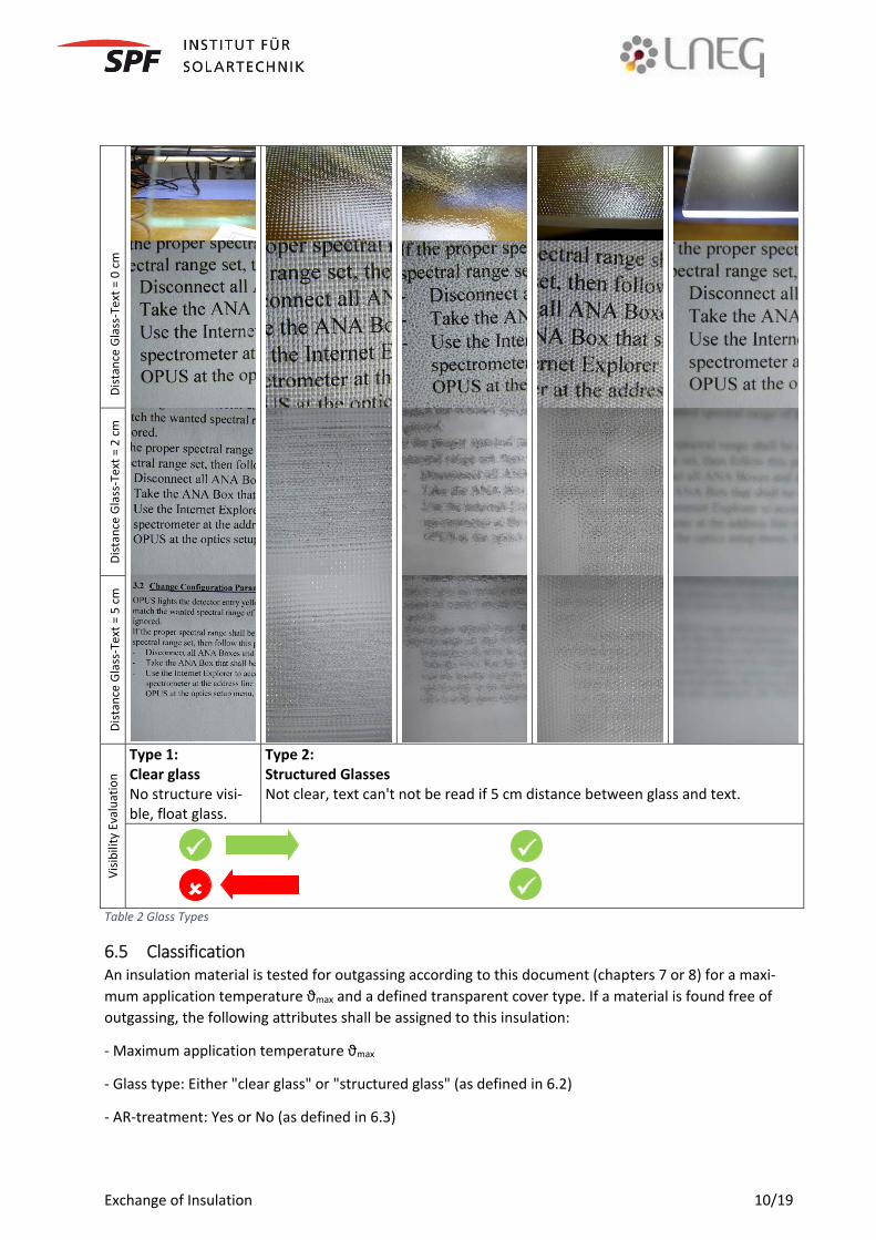
6.2 Visibility of outgassing on different glass types The visibility of outgassing is depending on the structure of the cover glass. In collectors with clear glass, the visibility of outgassing is much higher than for structured glasses. The difference concerning visibility of outgassing deposits between different types of structured glasses is however very small. For this rea-son, glasses are classified into two classes only: Structured glass and clear glass. The difference between structured and clear glass is illustrated in Table 2
The following rule applies: If outgassing is not visible on clear glass, then outgassing is not visible on structured glass. If outgassing is not visible on structured glass, it does NOT induce that outgassing is not visible on clear glass.
6.3 Outgassing on AR treated glass types Transparent covers with AR treatment (coating, edging) are more susceptible to different types of dirtying and hence to outgassing. Even small amounts of outgassing or other transparent deposits that are not necessarily visible by the unaided eye, may affect the performance considerably. For this reason, insula-tion materials intended to be used with covers with AR treatment shall be checked not only for visible traces of outgassing but also for their impact on the optical transmission of AR treated glasses. On the other hand, it may be assumed that insulations without outgassing on AR glasses will not show outgassing on untreated glasses.
The following rule applies: If outgassing is not visible/measurable on AR glass, then outgassing is not visible/measurable on un-treated glass. If outgassing is not visible/measurable on untreated glass, it does NOT induce that out-gassing is not visible/measurable on AR glass.
6.4 Covered insulations Some insulation materials are covered with aluminium foils, black fleece or similar. As some of these ma-terials are prone to induce outgassing, such covers must be considered as integral part of an insulation. The insulation has to be tested and registered with a defined cover (if available).
Exchange of Insulation 10/19
Dist
ance
Gla
ss-T
ext =
0 c
m
Dist
ance
Gla
ss-T
ext =
2 c
m
Dist
ance
Gla
ss-T
ext =
5 c
m
Visib
ility
Eva
luat
ion
Type 1: Clear glass No structure visi-ble, float glass.
Type 2: Structured Glasses Not clear, text can't not be read if 5 cm distance between glass and text.
Table 2 Glass Types
6.5 Classification An insulation material is tested for outgassing according to this document (chapters 7 or 8) for a maxi-mum application temperature ϑmax and a defined transparent cover type. If a material is found free of outgassing, the following attributes shall be assigned to this insulation:
- Maximum application temperature ϑmax
- Glass type: Either "clear glass" or "structured glass" (as defined in 6.2)
- AR-treatment: Yes or No (as defined in 6.3)
Exchange of Insulation 11/19
7 Outgassing test using a collector
7.1 General With this test procedure, the outgassing behaviour of an insulation material is assessed using a complete collector. As the thermal performance of the collector is not checked, the test procedure is therefore only applicable to collectors using glass covers without AR treatment.
This method is mainly intended for manufacturers of collectors wishing to replace their current supplier of insulation materials.
7.2 Method and test conditions A conventional flat plate collector of at least 2 m2 aperture area and portrait shape shall be built using the insulation material to be classified. Collector sampling is not required as this is a prototype test. The standard stagnation temperature of this collector has to be determined according to clause 9 of the ISO/DIS 9806:2016. If the collector is already Solar Keymark certified, the standard stagnation tempera-ture ϑstg determined in the test may be used under the condition that the thermal parameters of the insu-lation material are within the limits given in chapter 9, points 1-5. The insulation material is then consid-ered the same as the original material with respect to its thermal properties.
The collector is then tested according to clause 10 of ISO/DIS 9806:2016 (Exposure test) under one of the climate classes defined in Table 2 of ISO9806:2016. If there is no outgassing according clause 17 of ISO 9806:2016, the insulation material is deemed applicable for a temperature up to ϑmax calculated as follows:
Collector tested with Climate Class B: ϑmax=15+900/1000*(ϑstg - 30) Collector tested with Climate Class A: ϑmax=ϑstg Collector tested with Climate Class A+: ϑmax=40+1100/1000*(ϑstg - 30)
The test sample shall be photographed from the front side by the test lab several times during the whole procedure according to the following scheme: - Before exposing to the sun (upon receipt). - After one day of outdoor exposure. - After approximately 50% of the whole exposure. - After the full exposure. The pictures should be taken under similar sunny conditions and from similar view angles. If outgassing is visible by the unaided eye, it shall be documented with photos.
At the end of the test sequence, the collector shall be opened and inspected according to clause 17 of ISO/DIS 9806:2016 to - make sure that the insulation material under question was in the collector - make sure that the insulation material was in contact with the absorber - make sure that the insulation material is still in "operational conditions" (i.e. no burning). - make photos of the insulation material
7.3 Results and Reporting A test report shall be issued according to the ISO 9806:2016 including at least Annex XX (Description), clause 9 (Standard stagnation temperature), clause 10 (Exposure test) and clause 17 (Final inspection). In addition, this test report shall include the four pictures of the collector in exposure and picture of the insulation at final inspection. Furthermore the type of glass (structured / AR coated) and the calculated maximum application temperature shall be indicated.
Exchange of Insulation 12/19
8 Outgassing test using an insulation sample 8.1 General This more general method provides a laboratory method for the rating of outgassing of insulation materi-als. This method is important as it is much cheaper than the collector method and it is applicable for insu-lation manufacturers who want to supply their product to different collector manufacturers. Furthermore, the method is suitable for incoming goods control and several collector manufacturers have already in-stalled similar devices for quality surveillance.
Representative test samples of the insulation material are used for testing. The test samples are heated up to a well-defined maximum temperature in a test device as described in the following. The amount of outgassing is then checked and rated according to a clearly defined key.
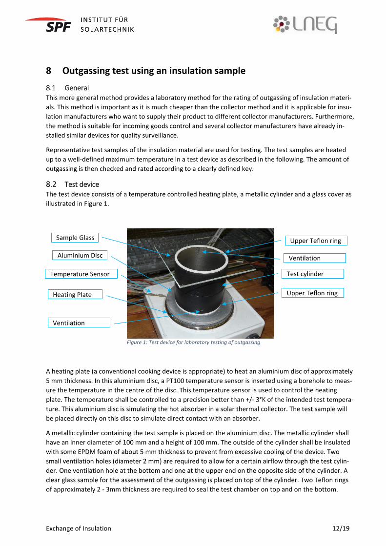
8.2 Test device The test device consists of a temperature controlled heating plate, a metallic cylinder and a glass cover as illustrated in Figure 1.
Figure 1: Test device for laboratory testing of outgassing
A heating plate (a conventional cooking device is appropriate) to heat an aluminium disc of approximately 5 mm thickness. In this aluminium disc, a PT100 temperature sensor is inserted using a borehole to meas-ure the temperature in the centre of the disc. This temperature sensor is used to control the heating plate. The temperature shall be controlled to a precision better than +/- 3°K of the intended test tempera-ture. This aluminium disc is simulating the hot absorber in a solar thermal collector. The test sample will be placed directly on this disc to simulate direct contact with an absorber.
A metallic cylinder containing the test sample is placed on the aluminium disc. The metallic cylinder shall have an inner diameter of 100 mm and a height of 100 mm. The outside of the cylinder shall be insulated with some EPDM foam of about 5 mm thickness to prevent from excessive cooling of the device. Two small ventilation holes (diameter 2 mm) are required to allow for a certain airflow through the test cylin-der. One ventilation hole at the bottom and one at the upper end on the opposite side of the cylinder. A clear glass sample for the assessment of the outgassing is placed on top of the cylinder. Two Teflon rings of approximately 2 - 3mm thickness are required to seal the test chamber on top and on the bottom.
Sample Glass Upper Teflon ring
Aluminium Disc
Heating Plate
Temperature Sensor Test cylinder
Upper Teflon ring
Ventilation
Ventilation
Exchange of Insulation 13/19
It is essential that all materials used for the setup of the test device are resistant against solvents/cleaning detergents required to clean the whole apparatus. The modular setup of the test device allows for easy cleaning of the device, furthermore single parts of the device can be easily replaced if soiled to such an extent that they cannot be cleaned anymore.
The surrounding air humidity during the testing shall be in the range of 0.006 - 0.0120 kg/kgAir
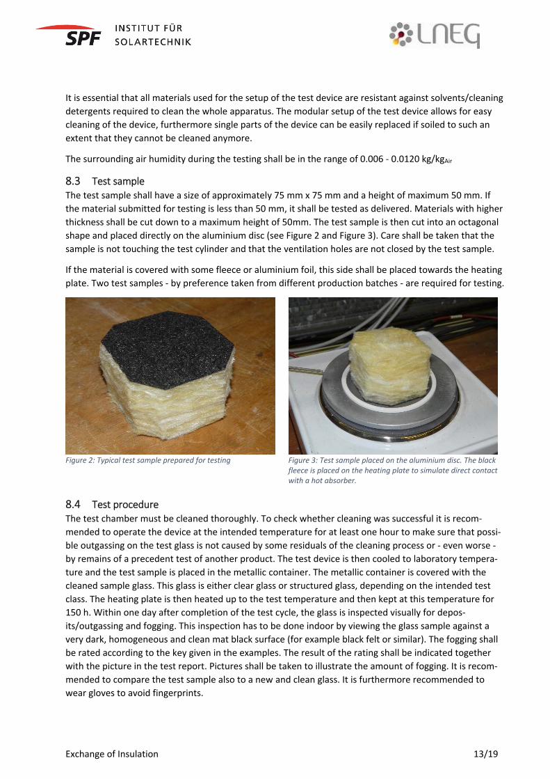
8.3 Test sample The test sample shall have a size of approximately 75 mm x 75 mm and a height of maximum 50 mm. If the material submitted for testing is less than 50 mm, it shall be tested as delivered. Materials with higher thickness shall be cut down to a maximum height of 50mm. The test sample is then cut into an octagonal shape and placed directly on the aluminium disc (see Figure 2 and Figure 3). Care shall be taken that the sample is not touching the test cylinder and that the ventilation holes are not closed by the test sample.
If the material is covered with some fleece or aluminium foil, this side shall be placed towards the heating plate. Two test samples - by preference taken from different production batches - are required for testing.
Figure 2: Typical test sample prepared for testing Figure 3: Test sample placed on the aluminium disc. The black fleece is placed on the heating plate to simulate direct contact with a hot absorber.
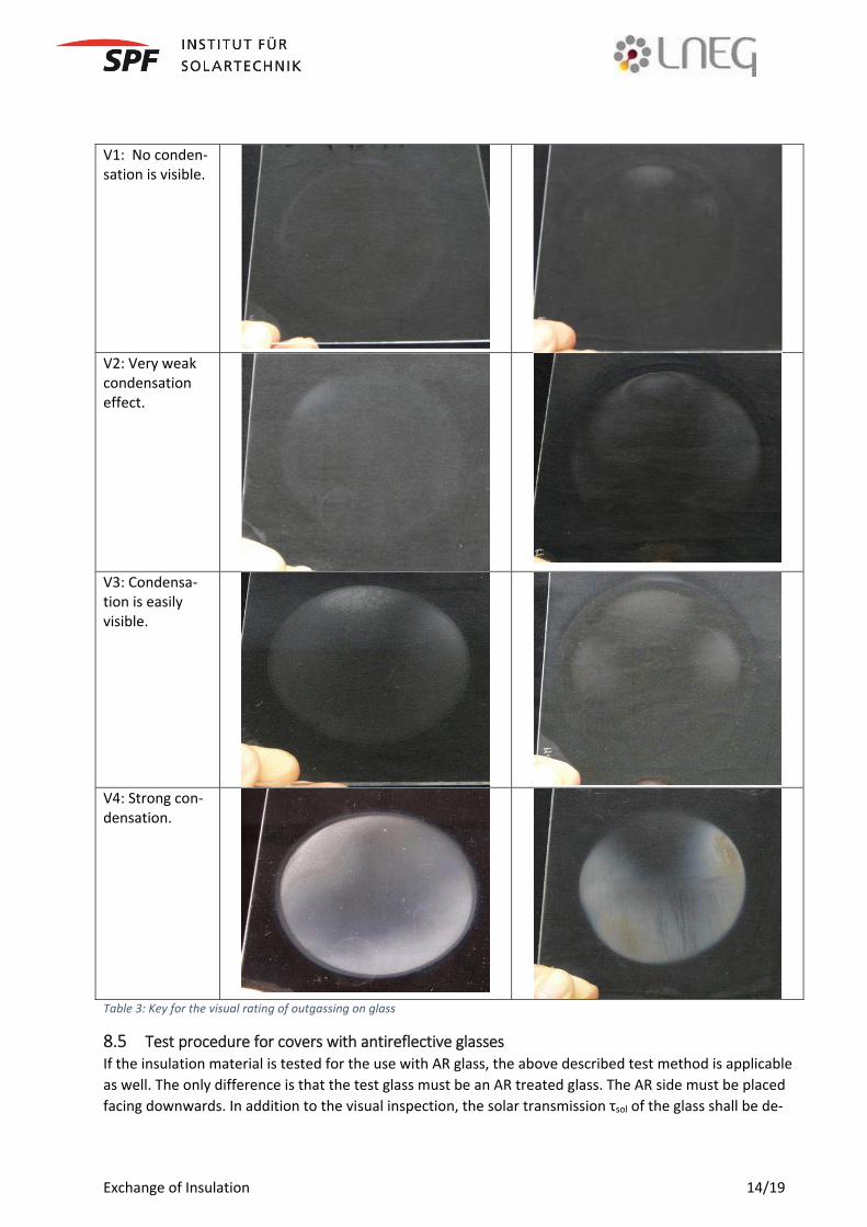
8.4 Test procedure The test chamber must be cleaned thoroughly. To check whether cleaning was successful it is recom-mended to operate the device at the intended temperature for at least one hour to make sure that possi-ble outgassing on the test glass is not caused by some residuals of the cleaning process or - even worse - by remains of a precedent test of another product. The test device is then cooled to laboratory tempera-ture and the test sample is placed in the metallic container. The metallic container is covered with the cleaned sample glass. This glass is either clear glass or structured glass, depending on the intended test class. The heating plate is then heated up to the test temperature and then kept at this temperature for 150 h. Within one day after completion of the test cycle, the glass is inspected visually for depos-its/outgassing and fogging. This inspection has to be done indoor by viewing the glass sample against a very dark, homogeneous and clean mat black surface (for example black felt or similar). The fogging shall be rated according to the key given in the examples. The result of the rating shall be indicated together with the picture in the test report. Pictures shall be taken to illustrate the amount of fogging. It is recom-mended to compare the test sample also to a new and clean glass. It is furthermore recommended to wear gloves to avoid fingerprints.
Exchange of Insulation 14/19
V1: No conden-sation is visible.
V2: Very weak condensation effect.
V3: Condensa-tion is easily visible.
V4: Strong con-densation.
Table 3: Key for the visual rating of outgassing on glass
8.5 Test procedure for covers with antireflective glasses If the insulation material is tested for the use with AR glass, the above described test method is applicable as well. The only difference is that the test glass must be an AR treated glass. The AR side must be placed facing downwards. In addition to the visual inspection, the solar transmission τsol of the glass shall be de-

Exchange of Insulation 15/19
termined before and after the test procedure according to the ISO 9050. The results shall be indicated in the test report
8.6 Test results, reporting and rating A test report shall be issued fulfilling the basic requirements of the ISO 17025 accreditation. The test re-port shall furthermore include at least - Description of the material and the sample including pictures of the samples before and after the test-ing. - The results of the Visual rating including photographs of the sample glasses - If AR glass: Measurements of the solar transmission of all the sample glasses before and after the test.
An insulation material is assumed acceptable for the use in solar thermal collectors without creating trou-blesome amounts of fogging if the rating of the visual inspection is either v1 or v2. If the material is to be used with AR treatment, the difference in solar transmission shall furthermore be less than 1.5% (i.e. τsol,after/ τsol,before ≥ 0.985). The test temperature will be the maximum application temperature ϑmax. If a material did not pass without outgassing, a maximum application temperature ϑmax of 0°C is assigned.
Exchange of Insulation 16/19
9 Acceptance and Tolerance Values
9.1 Replacement rules The insulation material X in a certified collector can be exchanged by another material Y without any re-testing and without notice to the certification body under the following conditions.
1. The materials X and Y shall fall under the same EN Standard of the series EN 13162 to EN 13171. 2. The specified size and dimension of the insulation remains unchanged to within +/- 10%. 3. The rated thermal conductance (lambda/thickness) of the new material(s) is within +/- 20% of the
original material. 4. The rated density according to EN 1602 shall be within +/-20%. 5. The Euroclass "Reaction-to-fire" shall be same or better for the replacement material. (see 5.1.2) 6. ϑmax(Y) ≥ ϑmax(X). If the maximum application temperature ϑmax of the material X is not known, it
shall be replaced by the measured and reported standard stagnation temperature as defined in the ISO 9806.
7. The rated glass structure for the new material Y is less critical than for the glass structure of the current material X according to Table 2.
8. If insulation X is tested with AR coating, it can be replaced only by a material Y if this is tested with AR
9. If insulation Y is to be used with any kind of cover, it has to be tested for outgassing with this cov-er.
10. Data sheets of the two insulation materials X and Y must be available and must be submitted to the test laboratory that has signed the Solar Keymark data sheet of the collector. If the material is not filed in the SK DB Insulation (Solar Keymark Data Base of insulation materials), the test labora-tory who is responsible for the SK datasheet has to assess and file the documentation:
11. The test lab has to confirm the acceptance of the replacement using the form sheet given in 9.3. 12. Cascaded modification of the insulation are not allowed. The reference is always the original col-
lector test where the Solar Keymark was issued for the first time.
Point 6-9 are required for collectors only where outgassing on the transparent cover is possibly visibly such as conventional flat plat collectors. For other collectors such as evacuated tube collectors or similar, the rating of outgassing (6-9) is not mandatory.
9.2 Step-by-step A manufacturer of certified collector wants to exchange the insulation of the collector for any reason. The following step-by-step procedure shall be followed:
1) Check if current insulation is listed in SK DB Insulation If YES -> 3) If NO -> 2)
2) Determine properties of the insulation that shall be replaced: ϑmax, Insulation Coating, Glass structure, AR coating, Density, Lambda, Fire Safety
3) Check whether physical properties of new material are acceptable for an exchange according to 9.1 (if the new material is registered in the SKN DB, the data indicated shall be used). If YES -> can use new insulation material. Proceed to 7) If NO -> STOP or 4)
Exchange of Insulation 17/19
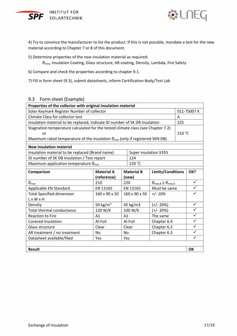
4) Try to convince the manufacturer to list the product. If this is not possible, mandate a test for the new material according to Chapter 7 or 8 of this document.
5) Determine properties of the new insulation material as required: ϑmax, Insulation Coating, Glass structure, AR coating, Density, Lambda, Fire Safety
6) Compare and check the properties according to chapter 9.1.
7) Fill in form sheet (9.3), submit datasheets, inform Certification Body/Test Lab
9.3 Form sheet (Example) Properties of the collector with original insulation material Solar Keymark Register Number of collector 011-7S007 X Climate Class for collector test A Insulation material to be replaced, Indicate ID number of SK DB Insulation 225 Stagnation temperature calculated for the tested climate class (see Chapter 7.2) or Maximum rated temperature of the insulation ϑmax (only if registered SKN DB)
210 °C
New insulation material Insulation material to be replaced (Brand name) Super insulation X355 ID number of SK DB Insulation / Test report 124 Maximum application temperature ϑmax 220 °C
Comparison Material A (reference)
Material B (new)
Limits/Conditions OK?
ϑmax 210 220 ϑmax,B ≥ ϑmax,A Applicable EN Standard EN 13165 EN 13165 Must be same Total Specified dimension L x W x H
160 x 90 x 50 160 x 90 x 50 +/- 10%
Density 50 kg/m3 45 kg/m3 (+/- 20%) Total thermal conductance 120 W/K 100 W/K (+/- 20%) Reaction to Fire A1 A1 The same Covered Insulation Al-Foil Al-Foil Chapter 6.4 Glass structure Clear Clear Chapter 6.2 AR treatment / no treatment No No Chapter 6.3 Datasheet available/filed Yes Yes Result OK
Exchange of Insulation 18/19
10 Proposal for a database
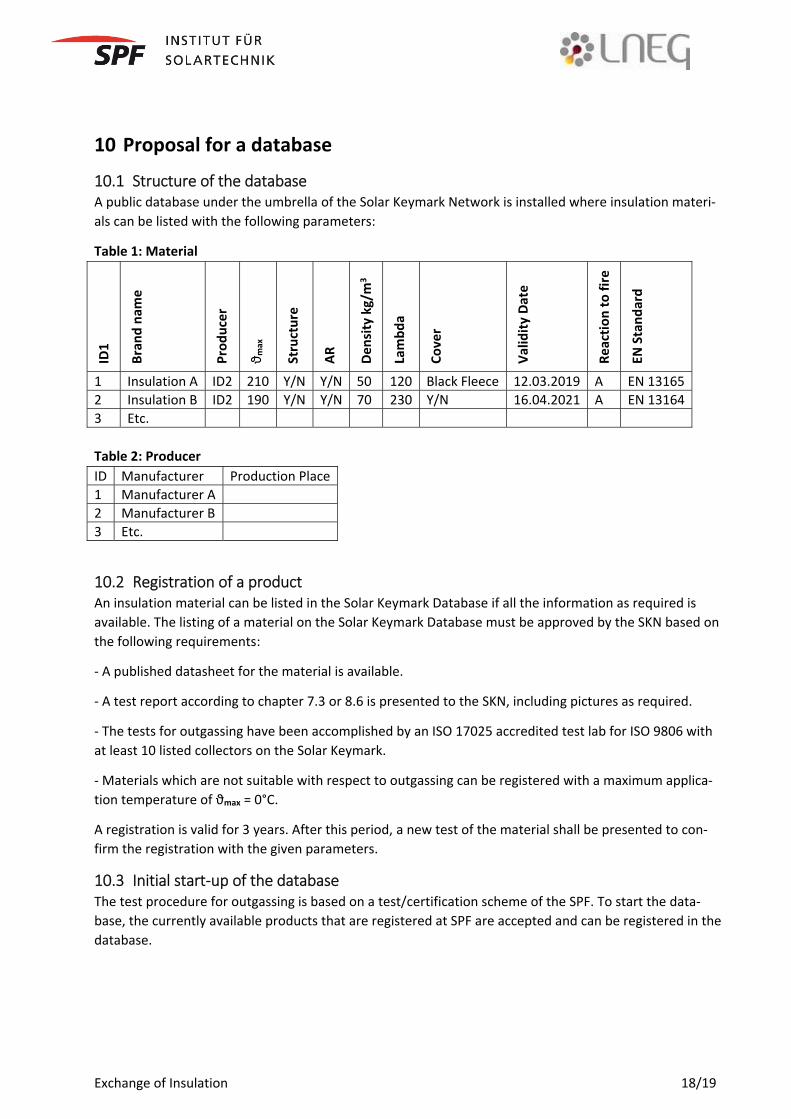
10.1 Structure of the database A public database under the umbrella of the Solar Keymark Network is installed where insulation materi-als can be listed with the following parameters:
Table 1: Material
ID1
Bran
d na
me
Prod
ucer
ϑ max
Stru
ctur
e
AR
Dens
ity k
g/m
3
Lam
bda
Cove
r
Valid
ity D
ate
Reac
tion
to fi
re
EN S
tand
ard
1 Insulation A ID2 210 Y/N Y/N 50 120 Black Fleece 12.03.2019 A EN 131652 Insulation B ID2 190 Y/N Y/N 70 230 Y/N 16.04.2021 A EN 131643 Etc. Table 2: Producer ID Manufacturer Production Place1 Manufacturer A 2 Manufacturer B 3 Etc.
10.2 Registration of a product An insulation material can be listed in the Solar Keymark Database if all the information as required is available. The listing of a material on the Solar Keymark Database must be approved by the SKN based on the following requirements:
- A published datasheet for the material is available.
- A test report according to chapter 7.3 or 8.6 is presented to the SKN, including pictures as required.
- The tests for outgassing have been accomplished by an ISO 17025 accredited test lab for ISO 9806 with at least 10 listed collectors on the Solar Keymark.
- Materials which are not suitable with respect to outgassing can be registered with a maximum applica-tion temperature of ϑmax = 0°C.
A registration is valid for 3 years. After this period, a new test of the material shall be presented to con-firm the registration with the given parameters.
10.3 Initial start-up of the database The test procedure for outgassing is based on a test/certification scheme of the SPF. To start the data-base, the currently available products that are registered at SPF are accepted and can be registered in the database.
Exchange of Insulation 19/19
11 Summary and next steps - This document will be presented to the Solar Keymark Network in Crete. If approved by the SKN, the system can be installed immediately. - If basically agreed, but comments need to be included, a WG is established and a version for final vote is being prepared for next SKN, based on an enquiry & commenting phase. The system is then presented for approval during the SKN spring meeting 2017.


![Untitled 2 [] · company t & s heating & a/c samsun mechanical inc energy tech insulations momper insulation rose and walker supply avila masonry llc hd3 masonry llc](https://img.pdfslide.net/doc/110x75/5f0cd6937e708231d43761a2/untitled-2-company-t-s-heating-ac-samsun-mechanical-inc-energy.jpg)