Embed Size (px)
Citation preview
Engineering Report of the prototype: “LNG Bunkering Barge”
Executive Summary
Engineering Report of the prototype: “LNG Bunkering Barge”
indexpage 4INTRODUCTION
GENERAL DESCRIPTION OF THE PROJECT
ENGINEERING CALCULATIONS
MAIN RESULTS
2.1 Barge “as it is” | 2.2 Propulsion | 2.3 Cargo Capacity
2.4 Daily Schedule | 2.5 Proposed Retrofitting | 2.6 Retrofit Decision
3.1 General Arrangement | 3.2 Naval Architecture | 3.3 Structure | 3.4 Engine Room Arrangement | 3.5 Electrical | 3.6 Safety | 3.7 Mooring | 3.8 Financial Risks
01020304
page 5
page 16
page 29

3
Engineering Report of the prototype: “LNG Bunkering Barge”
GLOSSARY OF ABREVIATIONS• BOG - Boil of gas
• BV - Bureau Veritas
• CL - Centre Line
• EEBD - Emergency Escape Breathing Device
• EN - Equipment Number
• EPIRB - Emergency Position Indicating Radiobeacon Station
• FiFi - Fight Fighting
• GVU - Gas Valve Unit
• HFO - Heavy Fuel Oil
• IGC - International Code of the Construction and Equipment of Ships Carrying Liquefied Gases in Bulk
• IGF - International Code of Safety for Ships Using Gases or Other Low-flashpoint Fuels
• IMO - International Maritime Organization
• LNG - Liquified Natural Gas
• LOA - Length Overall
• LPP - Length Between Perpendiculars
• MGO - Marine Gas Oil
• NG - Natual Gas
• NOx - Nitrogen Oxides
• SART - Search And Rescue Transmiter
• SOx - Sulphur Oxides
• STS - Ship to Ship

4
Engineering Report of the prototype: “LNG Bunkering Barge”
CROATIA
This report shows the main results of the engineering report carried out by Seaplace with the contribution of Boluda, Bureau Veritas, Dirección General de la Marina Mercante, Port Autority of Valencia, CIMNE and Fundación Valenciaport, in the framework of GAINN4MOS Action. In particular, this executive summary includes the conclusions of the basic engineering report of the retreport for the adaptation of the LNG Bunkering Barga Spabunker Cuarenta.
The following figure shows the area where the LNG bunkering barge is expected to provide bunkering service:
Figure 1. Location of the project
Valencia
LNG Spabunker CuarentaLNG
01 Introduction

5
Engineering Report of the prototype: “LNG Bunkering Barge”
02 General Description Of The Project
The LNG Bunkering Barge is encompassed in the GAINN4MOS project, which is constituted by 16 engineering studies and 11 prototypes and implementation elements in total.
Given the high flexibility of bunkering vessels, Ship To Ship (STS) bunkering is suitable for most types of vessels and is expected to become the main bunkering method for ships with a bunker demand of over 100 m³.
The high investment cost for bunker vessels is considered the main barrier for inaction in this sector together with the uncertainty of the LNG demand. For this reason, this prototype is based on the very likely forecast that the utilization of bunker barges will generally be low during the firsts years, requiring relatively high capacity utilization in later years.
The prototype will be designed to meet the potential growing demand of LNG at the Port of Valencia and other core ports in the Spanish Mediterranean area, covering real needs of STS bunkering until the demand reaches a certain level that makes profitable larger bunkering barges.
The prototype is based on the inclusion of one additional segregation of LNG to the existing barge as to supply gas as fuel to other vessels. The LNG bunker ship will have a storage capacity between 200 to 1 000 m³ as per vessel naval architecture capabilities. The bunker vessel will be loaded and unloaded by means of flexibles hoses or fixed arms at a flow rate of 100 to 1 000 m³ per hour, depending on the bunker installation of the receiving ship.
Retrofitting of existing barges requires:
1. Removing equipment installed on deck
2. Installing LNG tanks and associated equipment
3. Installing bunkering systems
In addition, in order to reduce this undesirable risk and aiming to control the financial risk associated to this project, BOLUDA TANKERS is going to retrofit the main engines to LNG.

6
Engineering Report of the prototype: “LNG Bunkering Barge”
The barge considered is SPABUNKER CUARENTA, and its main characteristics are shown in the table below:
02 General Description of The Project | Barge “as it is”
2.1 Barge “As it is”
Main particulars
LOA 75.13 m
LPP 69.78 m
Scantling Draught 6.20 m
Breadth Moulded 16.25 m
Depth 7 m
Block Coeficient 0.85 m
Displacement 6118 tons
Speed 12 knots
Load Capacity 3800 m³ HFO and 600 m³ of MDO
Year Built 2008
IMO No. 9416886
Class Notation CLASS I + HULL, MACH, Oil Tanker ESP / Flash Point Above 60, Unrestricted Navitagion, ATU-UMS
Flag Spanish
Owner BOLUDA TANKERS
Vessel Type Bunker
Main Power 2 x 1500 kW @ 1600 rpm
Auxiliary Power 2 x 451 kW @ 1500 rpm
Boilers 670 kW
Propulsion 2 x Azimuthal Thrusters SCHOTTLE SRP 1212 of 1380-1850 kW @ 750-1800 rpm
Hull Material Naval Steel
Figure 1. Spabunker Cuarenta

7
Engineering Report of the prototype: “LNG Bunkering Barge”
02 General Description of The Project | Barge “as it is”
Figure 2. General Arrangement of the current barge Figure 3 and 4. Spabunker Cuarenta
8
Engineering Report of the prototype: “LNG Bunkering Barge”
02 General Description of The Project | Propulsion
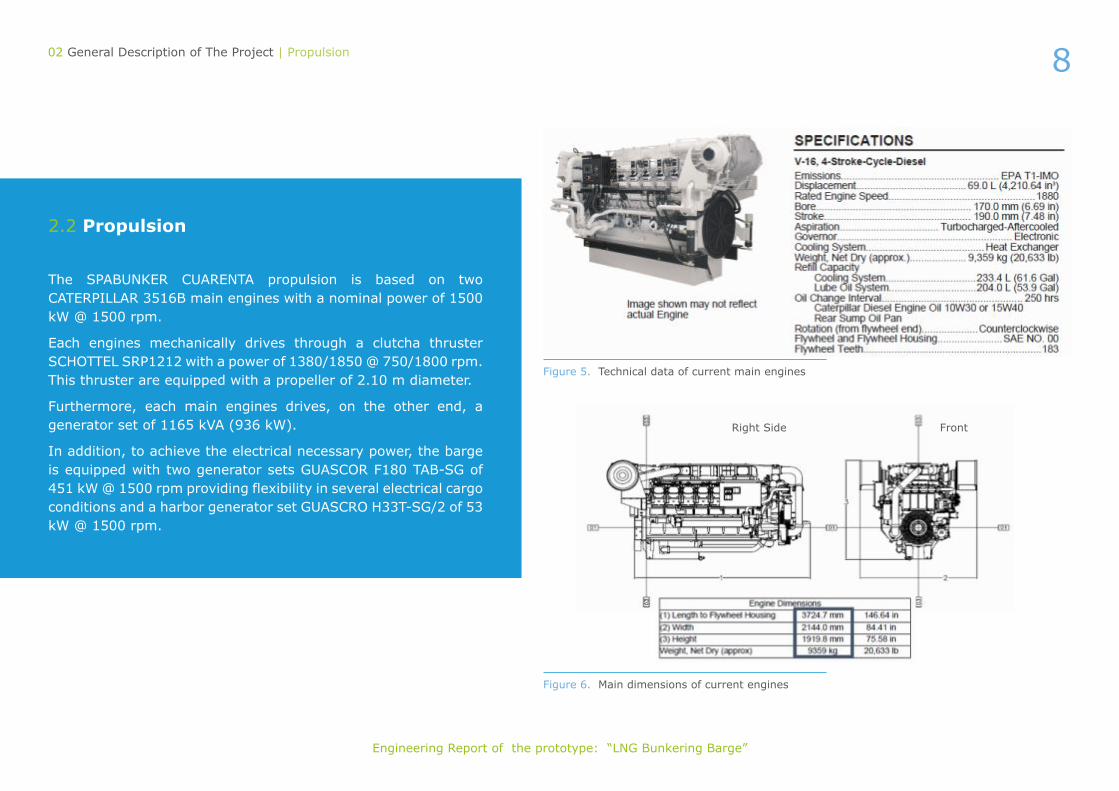
2.2 Propulsion
The SPABUNKER CUARENTA propulsion is based on two CATERPILLAR 3516B main engines with a nominal power of 1500 kW @ 1500 rpm.
Each engines mechanically drives through a clutcha thruster SCHOTTEL SRP1212 with a power of 1380/1850 @ 750/1800 rpm. This thruster are equipped with a propeller of 2.10 m diameter.
Furthermore, each main engines drives, on the other end, a generator set of 1165 kVA (936 kW).
In addition, to achieve the electrical necessary power, the barge is equipped with two generator sets GUASCOR F180 TAB-SG of 451 kW @ 1500 rpm providing flexibility in several electrical cargo conditions and a harbor generator set GUASCRO H33T-SG/2 of 53 kW @ 1500 rpm.
Figure 5. Technical data of current main engines
Figure 6. Main dimensions of current engines
Right Side Front
9
Engineering Report of the prototype: “LNG Bunkering Barge”
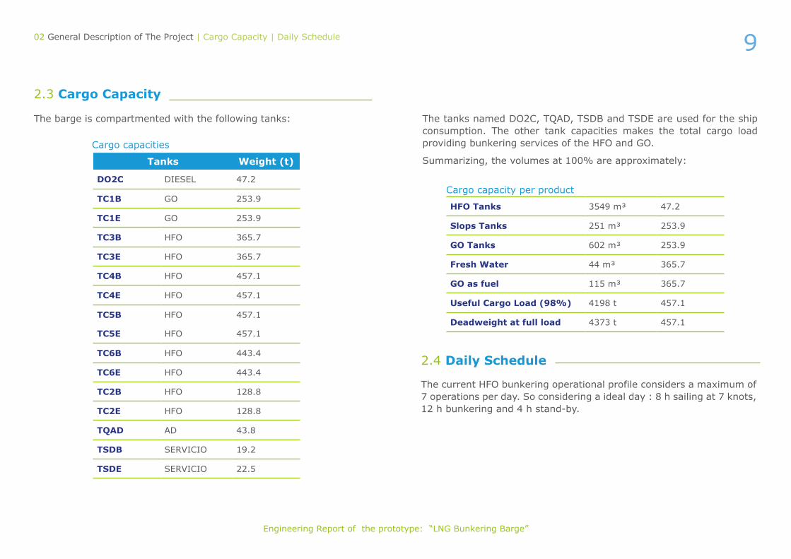
The barge is compartmented with the following tanks:
2.3 Cargo Capacity
The tanks named DO2C, TQAD, TSDB and TSDE are used for the ship consumption. The other tank capacities makes the total cargo load providing bunkering services of the HFO and GO.
Summarizing, the volumes at 100% are approximately:
2.4 Daily Schedule
02 General Description of The Project | Cargo Capacity | Daily Schedule
Tanks Weight (t)
DO2C DIESEL 47.2
TC1B GO 253.9
TC1E GO 253.9
TC3B HFO 365.7
TC3E HFO 365.7
TC4B HFO 457.1
TC4E HFO 457.1
TC5B HFO 457.1
TC5E HFO 457.1
TC6B HFO 443.4
TC6E HFO 443.4
TC2B HFO 128.8
TC2E HFO 128.8
TQAD AD 43.8
TSDB SERVICIO 19.2
TSDE SERVICIO 22.5
HFO Tanks 3549 m³ 47.2
Slops Tanks 251 m³ 253.9
GO Tanks 602 m³ 253.9
Fresh Water 44 m³ 365.7
GO as fuel 115 m³ 365.7
Useful Cargo Load (98%) 4198 t 457.1
Deadweight at full load 4373 t 457.1
Cargo capacities
Cargo capacity per product
The current HFO bunkering operational profile considers a maximum of 7 operations per day. So considering a ideal day : 8 h sailing at 7 knots, 12 h bunkering and 4 h stand-by.

10
Engineering Report of the prototype: “LNG Bunkering Barge”
The considered barge to retrofit is the SPABUNKER CUARENTA and its property of BOLUDA TANKERS. This retrofit can be separate into two big considerations: on one hand, the installation of LNG tanks to provide LNG bunkering to other vessels and gas as fuel in the propulsion plant, and on the other hand, the upgrading of the existing propulsion plant by engines capable to consume LNG as fuel and become the barge a cleaner vessel, reducing the NOx and SOx emissions.
The prototype is based on the inclusion of one additional segregation of LNG to the existing barge as to supply gas as fuel to other vessels. The LNG bunker ship will have a storage capacity between 200 to 1 000 m³ as per naval architecture capabilities. The bunker vessel will be loaded and unloaded by means of flexible hoses or fixed arms at a flow rate of 100 to 1 000 m³ per hour, depending on the bunker installation of the receiving ship.
The retrofitting of existing barge requires:
• Re- arrangeequipment installed on deck, pumps, hatchs, mixers, sensors, etc.
• Installing LNG tanks and associated equipment, paying special attention to steel foundation
• Installing bunkering system.
The retroffiting works in general are more difficult as the new design and capabilities have to cope with the existing design and hence additional restrictions have to be considered.
The Main Deck of the barge is completely full of equipment, pipes, etc. which will difficult any retrofitting work that must be carried out on it.
2.5 Proposed Retrofitting
02 General Description of The Project | Proposed Retrofitting
Considering this, the first attempt is to incorporate the LNG tanks below the Main Deck, using part of the space destined to the HFO or GO tanks.
Instead, because of the requierement of the Shipowner to maintain or slightly reduce the current cargo capacities of HFO and MDO, the LNG tanks shall be installed above the Main Deck.
Several options regarding the arrangement of the LNG tanks have been considered maximizing the LNG cargo capacity, minimizing HFO/MDO cargo reduction, complying with rules and regulations, stability criteria, structural requirements and operational limitations.
Finally, the intermediate solution was design a ship which would be capable to maintain the HFO and MDO cargo capacities, with an LGN tanks capacity of 600 m³ at least, that allows the ship to be propelled using part of the LNG cargo as fuel.
Furthermore, the other big handicap of this retrofit are the main engines. As included in the following sections, the existing main engines cannot be retroffited (according to the manufacturer) and the gas fuel / dual fuel engines are larger with similar power. The conversion will reduce as much as reasonable the impact in the existing ship trying to minimize the cost impact. The retrofitting of the barges has been discussed through different point of view considering Naval Architecture, Main Deck and Engine Room general arrangements premises.
In the following sections, it will be described the different alternatives considered and the solution adopted.

11
Engineering Report of the prototype: “LNG Bunkering Barge”
2.5.1 Rules and Regulations
The retrofitting of the SpabunkerCuarenta adding an additional LNG segregation, will modify the operational nature of the existing ship and this has required the compliance with all Class and International regulations as IGC code, IGD code and DCMM approval, for example.
02 General Description of The Project | Proposed Retrofitting
2.5.2 LNG Tanks
Among the avalaible options according to IGC Code it has been selected Type C tanks. The most suitable insulation for Type C tanks is vacuum.
In order to reduce the amount of LNG tanks to be installed, the solution adopted is the use of the LNG cargo tanks also for propulsion purposes, avoiding the need to install an additional tank.
2.5.2.1 LNG Capacity Requirements
The selection of the number, type, capacity and arrangement will be done based on the existing ship limitations, minimizing the conversion impact and maximizing the LNG cargo capacity. The main considerations taken into account are that the LNG capacity to be installed shall be between 200 and 1000 m³ for bunkering procedures, and It is stablished a minimum range of 10 days using LNG as fuel (gas mode).
LNG tanks shape and location
Bellow main deck
CON: significant HFO/MDO cargo reduction
Figure 7. Tank Plan below main deck
2.5.2.2 LNG Tanks Location
The scheme summarizes the alternatives for LNG tanks shape and location:

12
Engineering Report of the prototype: “LNG Bunkering Barge”
02 General Description of The Project | Proposed Retrofitting
Above main deck
Prismatic tanks Cylindrical tanks
PRO: high LNG capacity
CON: modification of vessel structure
One LNG tank aft
Three LNG tanks
Two LNG tanks in center line
Two LNG tanks aft
Four LNG tanks
CON: no permit using LNG as fuel
LNG tanks shape and location
CONS: HFO/MDO cargo reduction and central crane must be moved
CONS: HFO/MDO cargo reduction and negative trim generated
CONS: significant HFO/MDO cargo reduction and the installation of the mixer is not possible
Figure 8. Cylindrical LNG tanks Figure 9. LNG Prismatic tank sizing
Figure 10. One LNG Tank located in main deck aft
Figure 11. Two LNG Tanks located in Center Line
Figure 12. Two LNG tanks located aft Figure 13. Four LNG tanks

13
Engineering Report of the prototype: “LNG Bunkering Barge”
Three LNG Tanks
This alternative consisted on installing three LNG tanks, two aft of 235 m³ and one forward of 325 m³ (total of 800 m3). This provides higher flexibility in the LNG capacity reducing the impact in the main deck. The reduction of the HFO cargo will be of 16.5% in the worst condition (3 LNG tanks full). The forward LNG tank has been maximized according with the bridge visibility as per BV rules.
This configuration is accepted by the Shipowner.
02 General Description of The Project | Proposed Retrofitting
Figure 14. 3 x LNG tanks – 3D View
2.5.2 Gas As Fuel
The use of the LNG as fuel in the engine room have several advantages regarding the reduction in fuel cost (LNG is cheaper than MGO), the reduction in maintenance cost, the cleanness of the engine room and the control of the pressure and BOG in the LNG tanks.
To implement the retroffiting of the engine room, two main decisions have to be taken:
• Design Concept
• Equipment to be Gas fueled
Regarding the equipment to be gas fueled, in the existing engine room there are the Main Engines, the auxiliary engines and the boiler with the potential to be retrofitted.

14
Engineering Report of the prototype: “LNG Bunkering Barge”
The scheme bellow summarizes the alternatives analysis prior to making decisions about the retroffiting of the engine room:
02 General Description of The Project | Proposed Retrofitting
Design Concept Main engines
LNG As Fuel
ESD protected Gas Safe
CON: bigger impact of the retrofitting in the existing equipment of the engine room
Retrofitted New engines
CONS: a third party it’s needed (not the manufac-turer) and big impact in the equipment of the engine room
Pure Gas Dual Fuel
CONS: big dimension, high weight, laborious steel works, it’s needed to modified main structure, to re –engineered direct coupling between engine and propellers; safety concerns when only gas is used as propulsion; additional risk studies and extra safety measures
MAN WÄRTSILÄ
CON: bigger size

15
Engineering Report of the prototype: “LNG Bunkering Barge”
02 General Description of The Project | Proposed Retrofitting
Figure 15. Main engines (DAAF014777)
F1 for dry sump and F2 for deep wet sump
* Turbocharger at flywheel end Simensions in mm. Weight in toons.
Figure 16. Wärtsilä main dimensions
Other systems wich have been reviwed because of the convertion to use gas as fuel are:
• GVU: This unit regulates the gas feeding to the main engine in a safety conditions. With the engines selected, the manufacturer offers an approved type of GVU as independent equip which can be arranged in the Engine Room without airtight room.
• Auxiliary engines: they will remain as they are.
• Bolier: the existing boiler has been analyzed in order to evaluate the suitability of the retrofitting. Considering the pros and cons, the decision is not to retrofit the boiler.
• Piping: The entering point of the feeding pipes from the LNG tanks through the forward Engine Room’s bulkhead in order to carry the LNG up to the GVU, could oblige to relocate some cabinet located aft the mentioned bulkhead. The feeding pipes must be double wall with independent ventilation system in the Engine Room.
WÄRTSILÄ catalogue have the dual fuel gas engine 8L20DF developing 1480 kW @ 1200 rpm that fits regarding power requirements.

16
Engineering Report of the prototype: “LNG Bunkering Barge”
After the above study, the SPABUNKER CUARENTA will have the following main characteristics once the retrofit has been carried out:
LNG tanks solutionThree LNG tanks: 2 x 239 m³ located aft at both sides and 1 x 340 m³ located forward at centre line.
LNG cargo capacity Aprox. 800 m³
HFO cargo capacity1 3800 m³
MDO cargo capacity2 600 m³
Cargo pumps capacity 2 x 100 m³/h @ 7 bar
Autonomy 10 days in gas fuel mode
Main Engines 2x Wärtsila 8L20DF1Maximum capacity of the tanks designated to the HFO cargo services. The total HFO cargo capacity to be provided must be lesser in order not to overtake the scantling draught.
2Maximum capacity of the tanks designated to the MDO cargo services. The total MDO cargo capacity to be provided must be lesser in order not to overtake the scantling draught.
After the initial evaluation of different alternatives, the scope of the transformation will consist in the installation of three cylindrical LNG tanks above the main deck.
Furthermore, the main engines will be replaced by new dual engines which will permit operate the barge by LNG as fuel.
2.6 Retrofit Decision
02 General Description of The Project | Retrofit Decision
Retrofit main particulars
03 Engineering Calculations The scope for the Basic Engineering of the prototype has involved studies of following fields:
• General Arrangement
• Naval Architcture
• Structure
• Engine Room General Arrangement
• Piping Systems
• Mooring Arrangement
• Safety
• LNG Cargo Management
• LNG Transfer

17
Engineering Report of the prototype: “LNG Bunkering Barge”
03 Engineering Calculations | General Arrangement
3.1 General Arrangement
After the modifications the barge will be equipped by three Type C LNG tanks arranged on the Main Deck: 1x323 m³ located forward in CL and 2x235 m³ located aft at both sides of the barge.
The LNG bunker station has been arranged near the current HFO and GO bunker station in order to minimize the impact on the Main Deck. Nevertheless, all deck equipment (pumps, pipes, etc.) arranged on the current barge must be relocated to achieve a maximum LNG capacity of the tanks.
Other important part of the barge retrofitting is the new dual propulsion through the two new dual engines. This modification have an effect on the Engine Room arrangement duet this kind of engines are bigger than conventional engines and furthermore involves new equipment to be installed on board.
It is important to note that new general arrangement has been considering in order to minimize the impact on the barge and accordingly on the cost investment.
Figure 17. General Arrangement considered

18
Engineering Report of the prototype: “LNG Bunkering Barge”
03 Engineering Calculations | General Arrangement
Figure 18. Main deck main elements arrangement
In the modification in the arrangement of the deck have been evaluated those elements whose impact is not only related to the location of the equipment, but also it means some impact on the steel works, as HFO cargo pumps, GO/MDO cargo pumps, fuel mixer, hatches, cargo tanks levels and openings. There are several equipments that shall be relocated. The need to be re-arranged will impact in the cost of the retroffiting.

19
Engineering Report of the prototype: “LNG Bunkering Barge”
3.2 Naval Architecture
03 Engineering Calculations | Naval Architecture
Figure 19. Capacity tank plan
It is no necessary to modify the hull shape.
The retrofit of the barge requires the analysis of some parameters:
• Lightship weight distribution considering the weights estimated of the LNG tanks (tanks and supporting structure) and an additional 30 tons weight due to the new main engines and new equipment to be installed on the Engine Room.
• Intact stability and loading conditions with three LNG tanks arranged above the main deck, con-sidering the vessel as a gas tanker. According to the IGC Code and the IS208 Code for cargo ves-sels.
• Damage stability.
• Tonnage calculation: 2 787 gross tonnage, 1 323 net tonnage.
• Longitudinal strength – hull girder load: this analysis considers the weight distribution of the new barge’s configuration in order to calculate the blending moments once the LNG tanks has been installed on the Main Deck.
• Capacity plan: the modifications on the barge consider the installation of the three new LNG tanks and the new compartmentation in the ba-llast tanks.
20
Engineering Report of the prototype: “LNG Bunkering Barge”
3.3 Structure
Figure 20. Engine Room general arrangement
03 Engineering Calculations | Structure | Engine Room Arrangement
The main aim of the structural scope is to check if the current structure of the barge will withstand the new loads due the new distribution of the LNG tanks and the Engine Room retrofitting.
Furthermore, the main foundations of the LNG tanks must be designed according with the existing structure, providing an acceptable force transition from the LNG tanks to the ship structure.
Additionally it has been developed a FEM direct structural analysis of the LNG tank foundation of the refitted bunkering barge SPABUNKER 40.
The different FEM studies performed show that the original structure, the new added internal structure and the majority of components of the new tank supports structure behave perfectly for all the load requirements.
However, the upper plate of the tank supports structure should be modified. This upper plate should be revised either by increasing its thickness or by adding more structural components below to increase its stiffness.
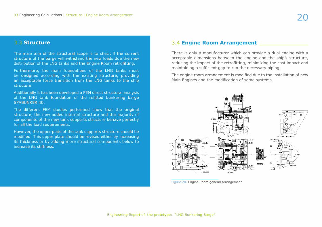
3.4 Engine Room Arrangement
There is only a manufacturer which can provide a dual engine with a acceptable dimensions between the engine and the ship’s structure, reducing the impact of the retrofitting, minimizing the cost impact and maintaining a sufficient gap to run the necessary piping.
The engine room arrangement is modified due to the installation of new Main Engines and the modification of some systems.

21
Engineering Report of the prototype: “LNG Bunkering Barge”
03 Engineering Calculations | Engine Room Arrangement
3.4.1 Additional Equipment List
There are two categories of new equipment: the one due to the retrofitting of LNG bunker barge and the oher due to use Gas as fuel.
The new equipment due to LNG bunker is installed in the main deck and can be resumed as follows:
• LNG tanks: Three LNG tanks are installed on deck two of 239 m³ located aft and one 340 m³ located forward.
• LNG transfer pumps: LNG transfer pumps with the related equipment have been installed in the process room between the tanks. The location of the process room in such area reduces the pipe lengths between the LNG tanks and the pums and minimizes the space requirements
• N2 generator: The N2 generator is installed in the castle deck using an existing store. The N2 generator will provide enough capacity to purge the lines in normal operation both the bunkering lines and the gas fuel lines.
• Safety equipment: As the inclusion of LNG in deck increment the safety requirements, several safety equipment has been added in order to fulfil the operational requirements of the bunker barge. Oil tanker and LNG carrier.
• Fire system for main deck: Similar to the safety equipment, new equipment has been added to fufil the new requirement of LNG carrier.
• The new equipment due to gas as fuel is installed mainly in the engine room but some of the equipment is also installed in the process room due to the location of the LNG tanks. It can be resumed as follow:
• Main Engines: Two new dual fuel engines are installed in the engine room.
• GVU: Two gas valve units (one per engine) are installed in the engine room. These equipment have huge impact due to their size and weight considering the limitations of space
• Associated equipment to the Main engines: The installation of the new main engine implies modifications (or at least verifications) of all the systems related to the (i.e. fuel system, refrigeration, compressed air, lube, ventilation, etc). During the engineering phase, the equipment related has been analyzed.
• LNG fuel pumps: Due to the location of the LNG tanks, two LNG fuel pumps have been installed in the process room (main deck) to provide gas fuel to the main engines.
• LNG vaporizers and NG heaters: Along with the LNG fuel pumps, LNG vaporizers and NG heaters have been installed in the process room in order to put the gas on specification according to the main engines requirements.
Considering the LNG bunker operation and gas as fuel operation, some of the equipment have been engineered in a way to be used in both operations (i.e. the LNG fuel pumps are also used as LNG spray pumps to cool down the LNG tanks).

22
Engineering Report of the prototype: “LNG Bunkering Barge”
03 Engineering Calculations | Engine Room Arrangement
3.4.2 Piping System
The main systems of the ship has been analyzed. Some of the pipes has been modified due to the retrofitting, some are new and some are kept the same.
3.4.3 Ballast System
The ballast system of the ship is expected not to be modified but after the stability calculations, new requirements in the ballast system are needed. The modification implies the communication of the TL5B and TL5E tanks in order to achieve a symmetrical flood and the heel is maintained under regulatory limits. Additionally, the aft ballast tanks are reduced to reduce the impact of the damage stability in that area.
3.4.3.1 Fire System For Lng
As the retroffited wessel will have the LNG carrier class notation, it has to be installed a fixed dry chemical powder system. Two chemical units with two powder monitors shall be arranged on deck providing the fire suppression capability required.
According to IGC code the ship must be provided with a water-spray system, for cooling, fire prevention and crew protection. It shall be installed to cover exposed on-deck storage tanks, gas process units, bunkering pipes, emergency shut-down valves and exposed boundaries of
superestructure facing the cargo area. Two water spray pumps have been included for this purpose, one on engine room and the other one in forward thruster room.
3.4.3.2 Sea Water/Fresh Water Cooling System
The installation of the new main engines have an impact in the cooling requirements. The two main modifications of the systems are:
• For sea water system: new heat exchagers to comply with the cooling requirements of new engine manufacture.
• For fresh water cooling: a new system according to engine manufacture.
3.4.3.3 Fuel Oil System
The system will remain the same considering the auxiliary generator needs and the boiler needs. For the main engines, a pilot fuel pump has to be included (one per engine) as to provide the required fuel during gas mode (MGO less than 3%).
3.4.3.4 Lng Loading And Discharge System
The new LNG loading and discharge system is related to the LNG bunkering capacity.
The concerned operations are: loading of the LNG tanks from a terminal and discharging the LNG tanks to a gas fuel ship or satellite terminal. The philosophy followed is the redundancy of the system providing the maximum flexibility to the system.

23
Engineering Report of the prototype: “LNG Bunkering Barge”
3.4.3.5 Fuel Gas Supply System
The fuel gas supply system is related to the new main engines to be installed. The system is designed to use the LNG stored in the LNG tanks and use it as fuel. As the Natural Gas has to be at spec prior to the GVU installed in the engine room, the systems comprises the LNG fuel pumps, LNG vaporizers and LNG heaters. The system is able to take the LNG at -163 ºC and to supply to the main engines at 30ºC.
3.4.3.6 Water/Glycol Heating System
The required energy for vaporizing and heating is taken through a water-glycol system using the heat of the main engines. Additionally electric heaters are used to complement the energy requirements in the different situations.
3.4.3.7 Inert Gas Supply System
Considering the existing regulations, an inert gas system shall be added to the ship. The system is designed to be able to inert the gas pipes before and after the bunkering operation and also to inert the gas fuelled pipes from the process room to the GVU and the main engines both in normal operation and emergency situations.
3.4.3.8 Ventilation One-Line Diagram
The implementation of the LNG on board defines several hazardous areas that shall be specifically ventilated to maintain the operation in the safe mode (alternately, permanent inert gas can be provided)
As the LNG tanks are located on open deck, no specific ventilation of the area is needed.
For the enclosed spaces, two different areas are considered:
• Engine room: As the engine room is designed under the gas safe principle, there is no specific requirement. On the other hand, the ventilation of the double walled pipes in the engine room is assured by means of specific ventilation.
• Process room: As the process room contains the main equi-pment handling the LNG and Natural gas (pumps, heaters, vaporizers, etc.) specific ventilation has been designed for the operation.
03 Engineering Calculations | Engine Room Arrangement

24
Engineering Report of the prototype: “LNG Bunkering Barge”
3.5 Electrical
03 Engineering Calculations | Electrical
Figure 21. Electrical one-line diagram
The modification of the main engines (impacting the electrical generation on board) and the new equipment (consumers) to be installed to provided LNG bunkering capacity plus gas fuel capacity, mean that the electrical configuration and load distribution have to be verified. The retroffited barge shall be able to operate in the present configuration and in the new one. So there is a new electrical diagram:
Figure 22. Electrical load demand
It has been developed the preliminary electrical load analysis of the LNG bunkering barge adding the new consumers of the proposed retrofitting. The load balance has been estimated for seven operation modes as shown in the following figure:

25
Engineering Report of the prototype: “LNG Bunkering Barge”
03 Engineering Calculations | Safety
3.6 Safety
As the existing ship complies with all the regulatory mandates regarding safety, the retrofitted barge will do so in a similar way but complying with the safety as oil tanker, as LNG carrier and as gas fueled ship. All the above equipment must comply with the applicable requirements described in the corresponding rules.
The new life saving equipment that is arranged on the barge is:
Description Total
Life boat 1
Inflatable life raft 2
Rescue boat 1
Davit launched inflatable life raft 2
Embarkation ladder 1
Pilot ladder 1
Lifebuoy with 30 m line 2
Lifebuoy with automatic light and smoke signal 2
Lifebuoy with automatic light 2
Lifebuoy 2
Rigid lifejacked for adult 15
Inmersion suits 12
Thermal protective aid 4
Survival craft portable radio 3
SART 2
Rocket parachute flares 12
Line throwing rechargeable appliance 1
Muster station 2
EPIRB 1
Medical locker 1
EEBD 3
Floating smoke signal 2
Flags and signal code 1
Tables of rescue signal 1
Lifesaving equipment
26
Engineering Report of the prototype: “LNG Bunkering Barge”
03 Engineering Calculations | Safety
Description Total
Smoke detector 20
Flame detector 6
Heat detector 1
Push bottom for fire alarm 1
Manually operated call point 10
Manually operated call pint water 6
Fire control panel 1
Fire hydrant 45 mm diameter 2
Fire hydrant 70 mm diameter 14
International shore connection 1
Sea water fire hose and box 9
Fire alarm bell 17
Horn fire alarm 5
Water alarm horn 5
Ship’s bell 1
Day signals and marks 1
Emergency bilge pump 1
Second fire pump 1
Emergency Sea water pump 1
Water spray main pump 1
Water spray pump 1
Space with CO2 extinguisher system 3
CO2 audible and visible alarm 7
CO2 battery 1
Portable foam applicator 20 liters 2
Foam tank 1
Water/Foam monitor 3
Foam applicator 4
Connection for foam applicator 3
Fixes powder fire extinguishing installation 2
Powder section valve 5
Powder monitor 2
Powder fire hose and box 3
Space protected by water-fire 1
Pressure water system valves 1
Water-spray system valves 1
Portable fire exinguishers 21
Spare charges for fire extinguishers 2
Emergency battery pack 2
Fire locker 3
Oxygen and combustible gas analyser 1
Fire-fighting pail with line 3
Fireman outfit 4
Air compressor for breathing apparatus 1
EEBD 5
Inert gas installation 1
Set of safety equipment gas 3
Closing device accommodation and service space 10
Closing device machinery space 5
Draft damper in vent duct 3
Ventilation fan accommodation and service space 5
Ventilation fan machinery space 4
Multi-split air conditioning 2
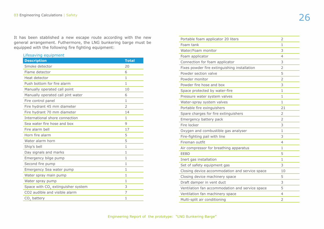
It has been stablished a new escape route according with the new general arrangement. Futhermore, the LNG bunkering barge must be equipped with the following fire fighting equipment:
Lifesaving equipment

27
Engineering Report of the prototype: “LNG Bunkering Barge”
According with the BV rules (considering IGC or IGF Code the different dangerous areas (Zones 0, 1 and 2) have been defined. It is important to note that hazardous zones 1 and 2 around the LNG bunkering sta-tion are only considered as hazardous during bunkering. The bunkering lines will be inerted when the bunkering operation is completed. After the lines are inerted, the bunkering station will not be considered as a hazardous area.
The cargo tanks, slop tanks, pipes and equipment containing the cargo in the current barge (defined as Oil Tanker) are classified as zone 2.
With the LNG Tanks installed on board, the dangerous areas are modi-fied according with the BV rules. The classification of the spaces shall be:
• Zone 0:
• LNG Tanks above deck,
• Vent mast,
• Pipes and Equipment containing LNG.
• Zone 1:
• Process Room,
• Ventilation of the process room,
• Tank connection space of LNG Tanks,
• Manifold (Ps & Sb),
• Ventilation from the GVU of main engines,
• Ducts around gas pipes.
03 Engineering Calculations | Safety
• Zone 2:
• Cargo tanks & slop tanks,
• Air lock,
• CO2 Room,
• Paint Store & Store,
• N2 & Dry Powder Room,
• Emergency FiFi Pump Room,
• The outer surface of LNG Tank exposed to the weather (an area within 2.4 m).
Enclosed spaces with access doors facing the cargo area in hazardous zone, will be considered hazardous areas as well.
In order to detect a possible gas leak, gas detectors and audible and vi-sual alarms have been arranged on the barge. The number of detectors must has been arranged according with the size, layout and ventilation of the space. Furthermore, two sets of portable gas detection equipment shall be provided on board. The audible and visual alarms from the gas detection equipment must been located in each compartment equipped with gas detectors. The detectors must be continuous detections type with immediate response. The audible and visible alarms from the gas detection equipment shall initiate on the navigation bridge.
LNG heating circuit must be equipped with gas detectors.
It has been analysed the fire integrity of decks and bulkheads according with the IGC Code and SOLAS in case of fire.
28
Engineering Report of the prototype: “LNG Bunkering Barge”
03 Engineering Calculations | Mooring
The EN has been calculated according with the BV rules for ships with perpendicular superstructure front bulkhead.
The increment in the EN has been further discussed with Class in order to verify if the present mooring equipment can be used or further upgrading is needed.
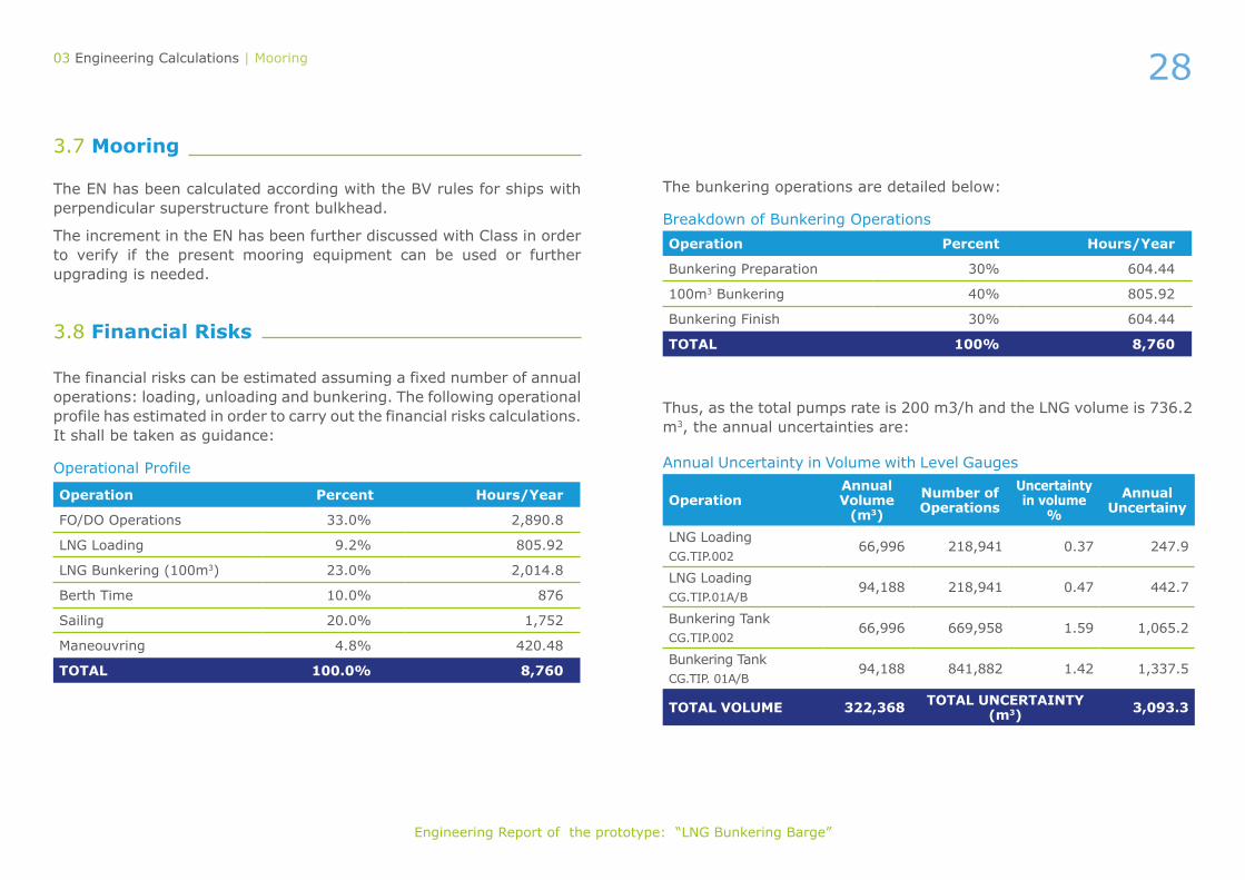
3.8 Financial Risks
The financial risks can be estimated assuming a fixed number of annual operations: loading, unloading and bunkering. The following operational profile has estimated in order to carry out the financial risks calculations. It shall be taken as guidance:
3.7 Mooring
The bunkering operations are detailed below:
Thus, as the total pumps rate is 200 m3/h and the LNG volume is 736.2 m3, the annual uncertainties are:
Operational Profile
Breakdown of Bunkering Operations
Operation Percent Hours/Year
FO/DO Operations 33.0% 2,890.8
LNG Loading 9.2% 805.92
LNG Bunkering (100m3) 23.0% 2,014.8
Berth Time 10.0% 876
Sailing 20.0% 1,752
Maneouvring 4.8% 420.48
TOTAL 100.0% 8,760
Operation Percent Hours/Year
Bunkering Preparation 30% 604.44
100m3 Bunkering 40% 805.92
Bunkering Finish 30% 604.44
TOTAL 100% 8,760
Annual Uncertainty in Volume with Level Gauges
OperationAnnualVolume
(m3)
Number of Operations
Uncertaintyin volume
%
Annual Uncertainy
LNG Loading CG.TIP.002
66,996 218,941 0.37 247.9
LNG Loading CG.TIP.01A/B
94,188 218,941 0.47 442.7
Bunkering Tank CG.TIP.002
66,996 669,958 1.59 1,065.2
Bunkering Tank CG.TIP. 01A/B
94,188 841,882 1.42 1,337.5
TOTAL VOLUME 322,368 TOTAL UNCERTAINTY (m3) 3,093.3

29
Engineering Report of the prototype: “LNG Bunkering Barge”
The action consists of retrofitting the SPABUNKER CUARENTA bunkering barge. Its retrofit can be separated into two big consi-derations: on one hand, the installation of LNG tanks to provide LNG bunkering to other vessels and gas as fuel in the propulsion plant, and on the other hand, the upgrading of the existing pro-pulsion plant by engines capable to consume LNG as fuel and become the barge a cleaner vessel, reducing the NOx and SOx emissions
04 Main Results
Main particulars
LOA 75.13 m
LPP 69.78 m
Scantling Draught 6.20 m
Breadth Moulded 16.25 m
Depth 7 m
Block Coeficient 0.85 m
Displacement 6118 tons
Speed 12 knots
Load Capacity 3800 m³ HFO and 600 m³ of MDO
Year Built 2008
IMO No. 9416886
Class Notation CLASS I + HULL, MACH, Oil Tanker ESP / Flash Point Above 60, Unrestricted Navitagion, ATU-UMS
Flag Spanish
Owner BOLUDA TANKERS
Vessel Type Bunker
Main Power 2 CATERPILLAR 3516B with a nominal power of 1500 kW @ 1600 rpm
Auxiliary Power 2 generators GUASCO F180 TAB-SG of 451 kW @ 1500 rpm
Boilers 670 kW
Propulsion 2 x Azimuthal Thrusters SCHOTTLE SRP 1212 of 1380-1850 kW @ 750-1800 rpm
Hull Material Naval Steel
Initial Barge
The main characteristics of the barge are shown in the table below:

30
Engineering Report of the prototype: “LNG Bunkering Barge”
The barge has 16 tanks four of wich are used for the ship consumption. The other tank capacities makes the total cargo load providing bunkering services of the HFO and GO. Summarizing, the volumes fo the tanks at 100% are approximately:
Proposed RetrofittingAmong the avalaible options according to IGC Code it has been selected Type C tanks, using vacuum as insulation. In order to reduce the amount of LNG tanks to be installed, the solution adopted is the use of the LNG cargo tanks also for propulsion purposes, avoiding the need to install an additional tank.
The LNG capacity to be installed shall be between 200 and 1000 m³ for bunkering procedures, and It is stablished a minimum range of 10 days using LNG as fuel (gas mode).
After the analysis, it is selected to install three cylindrical LNG tanks above main deck, two aft of 235 m³ and one forward of 325 m³ (total of 800 m3).
04 Main Results
HFO Tanks 3549 m³
Slops Tanks 251 m³
GO Tanks 602 m³
Fresh Water 44 m³
GO as fuel 115 m³
Useful Cargo Load (98%) 4198 t
Deadweight at full load 4373 t
Solution for LNG tanks
Bellow main deck
CON: significant HFO/MDO cargo reduction
Above main deck
Prismatic tanks Cylindrical tanks
PRO: high LNG capacity
CON: modification of vessel structure
One LNG tank aft
Three LNG tanks
Two LNG tanks in center line
Two LNG tanks aft
Four LNG tanks
CON: no permit using LNG as fuel
LNG tanks shape and location
CONS: HFO/MDO cargo reduction and central crane must be moved
CONS: HFO/MDO cargo reduction and negative trim generated
CONS: significant HFO/MDO cargo reduction and the installation of the mixer is not possible

31
Engineering Report of the prototype: “LNG Bunkering Barge”
Finally, the SPABUNKER CUARENTA will have the following main characteristics once the retrofit has been carried out:
The retroffited will affect other systems of the barge as structure, the engine room, piping systems and safety systems, for example.
The use of the LNG as fuel in the engine room have several advantages regarding the reduction in fuel cost (LNG is cheaper than MGO), the reduction in maintenance cost, the cleannest of the engine room and the control of the pressure and BOG in the LNG tanks. To implement the retroffiting of the engine room, two main decisions have to be taken the design concept an the equipment to be Gas fueled.
LNG tanks solutionThree LNG tanks: 2 x 239 m³ located aft at both sides and 1 x 340 m³ located forward at centre line.
LNG cargo capacity Aprox. 800 m³
HFO cargo capacity1 3800 m³
MDO cargo capacity2 600 m³
Cargo pumps capacity 2 x 100 m³/h @ 7 bar
Autonomy 10 days in gas fuel mode
Main Engines 2x Wärtsila 8L20DF
04 Main Results
Design Concept Main engines
LNG As Fuel
ESD protected Gas Safe
CON: bigger impact of the retrofitting in the existing equipment of the engine room
Retrofitted New engines
CONS: a third party it’s needed (not the manufac-turer) and big impact in the equipment of the engine room
Pure Gas Dual Fuel
CONS: big dimension, high weight, laborious steel works, it’s needed to modified main structure, to re –engineered direct coupling between engine and propellers; safety concerns when only gas is used as propulsion; additional risk studies and extra safety measures
MAN WÄRTSILÄ
CON: bigger size


![Food security and nutrition: building a global narrative ... · EXECUTIVE SUMMARY EXECUTIVE SUMMARY EXECUTIVE SUMMARY EXECUTIVE SUMMAR Y [ 2 ] This document contains the Summary and](https://img.pdfslide.net/doc/110x75/5ff5433612d22125fb06e6b5/food-security-and-nutrition-building-a-global-narrative-executive-summary-executive.jpg)