Embed Size (px)
Citation preview
Student Manual
138 FACET by Lab-Volt
AM Reception Analog Communications
Exercise 1: RF Stage
EXERCISE OBJECTIVE
EXERCISE DISCUSSION
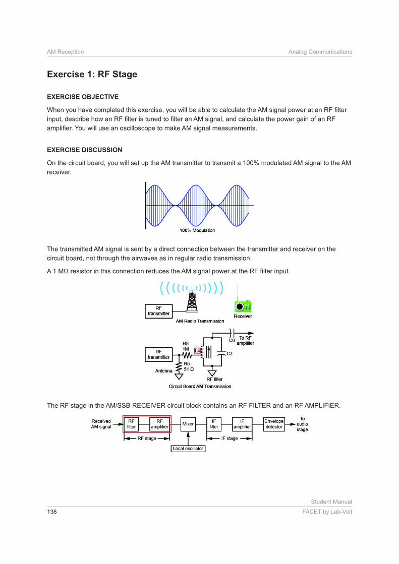
On the circuit board, you will set up the AM transmitter to transmit a 100% modulated AM signal to the AM
receiver.
The transmitted AM signal is sent by a direct connection between the transmitter and receiver on the
circuit board, not through the airwaves as in regular radio transmission.
A 1 M
Student Manual
FACET by Lab-Volt 139
Analog Communications AM Reception
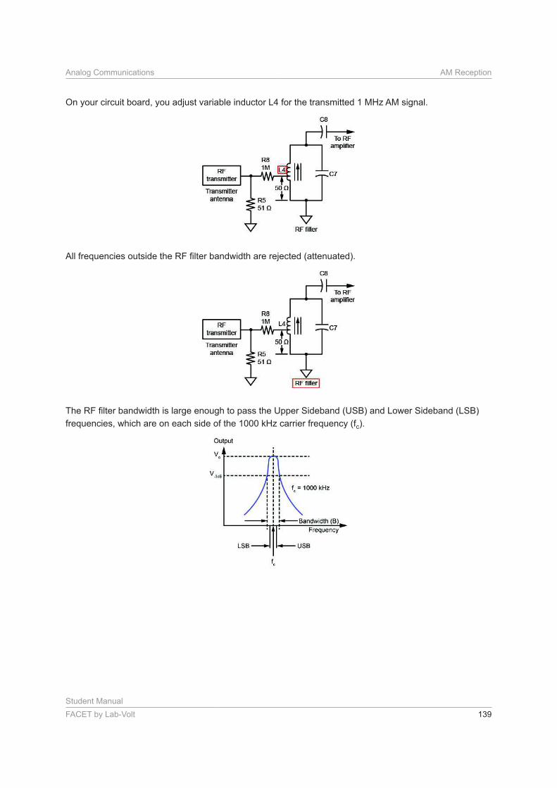
On your circuit board, you adjust variable inductor L4 for the transmitted 1 MHz AM signal.
frequencies, which are on each side of the 1000 kHz carrier frequency (fc).
Student Manual
140 FACET by Lab-Volt
AM Reception Analog Communications
c
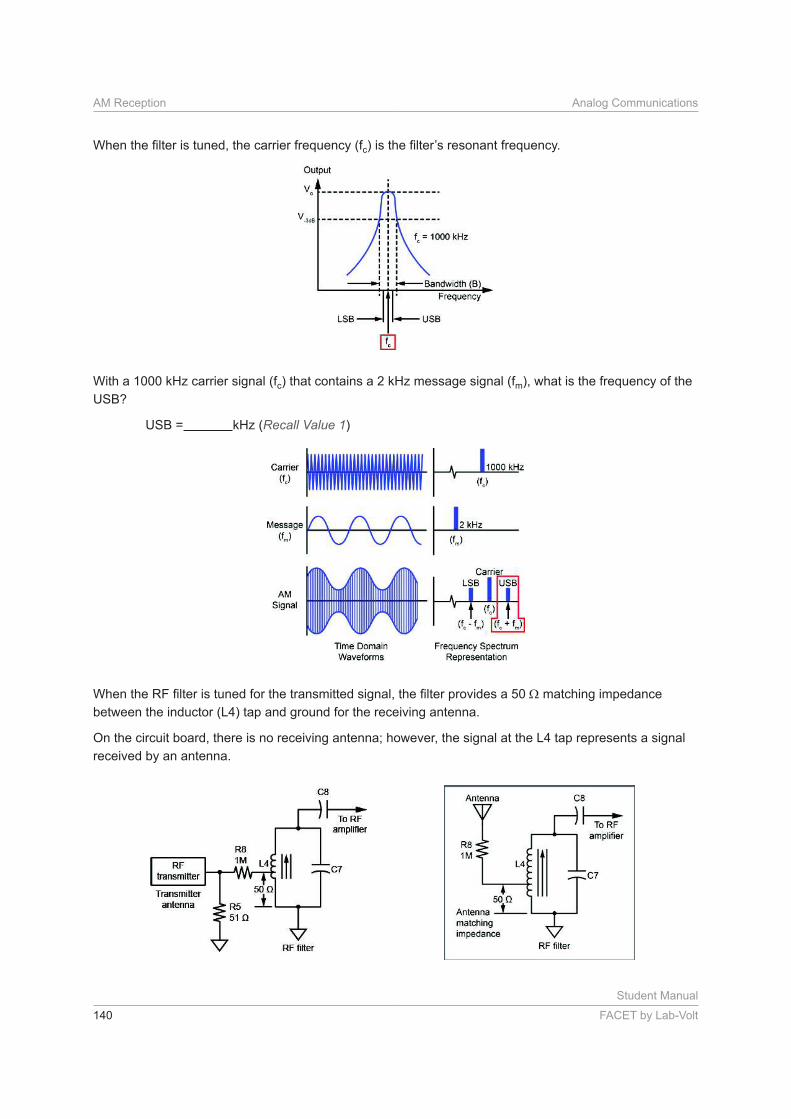
With a 1000 kHz carrier signal (fc) that contains a 2 kHz message signal (fm), what is the frequency of the
USB?
USB = kHz (Recall Value 1)
matching impedance
between the inductor (L4) tap and ground for the receiving antenna.
On the circuit board, there is no receiving antenna; however, the signal at the L4 tap represents a signal
received by an antenna.
Student Manual
FACET by Lab-Volt 141
Analog Communications AM Reception
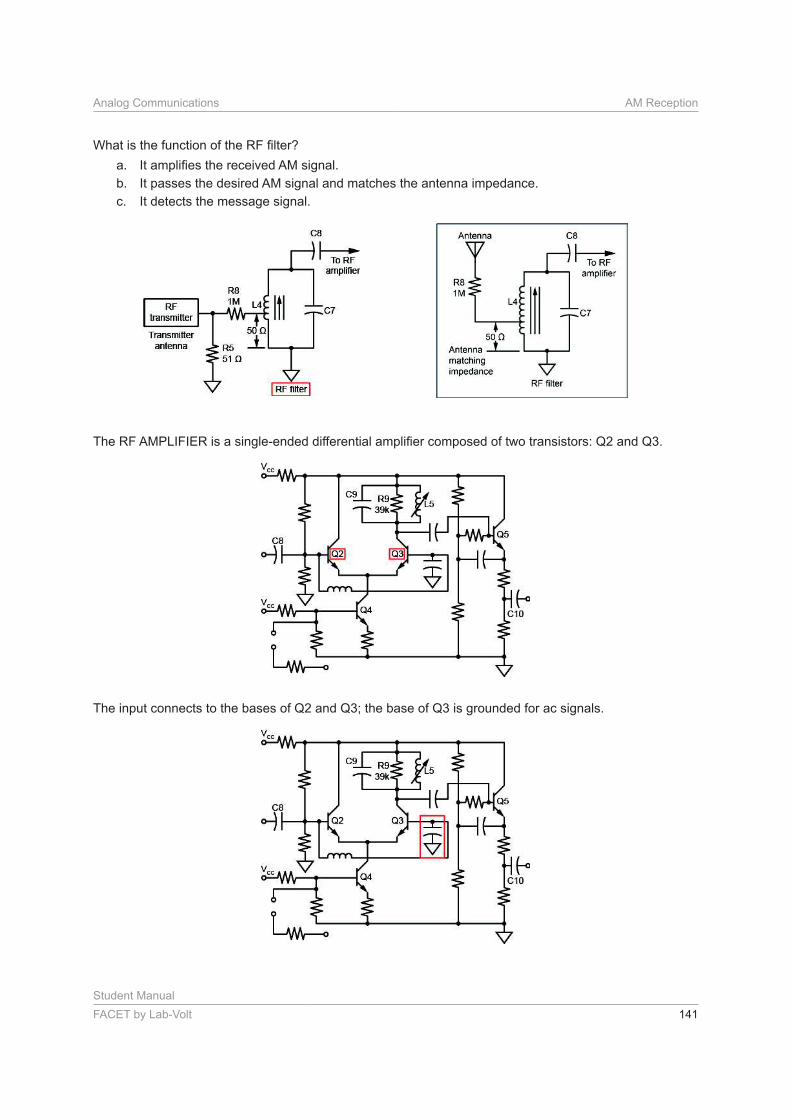
a.
b. It passes the desired AM signal and matches the antenna impedance.
c. It detects the message signal.
The input connects to the bases of Q2 and Q3; the base of Q3 is grounded for ac signals.
Student Manual
142 FACET by Lab-Volt
AM Reception Analog Communications
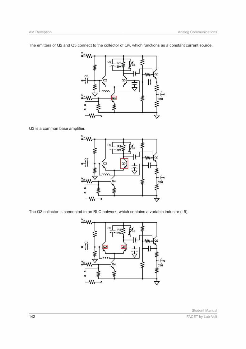
The emitters of Q2 and Q3 connect to the collector of Q4, which functions as a constant current source.
The Q3 collector is connected to an RLC network, which contains a variable inductor (L5).
Student Manual
FACET by Lab-Volt 143
Analog Communications AM Reception
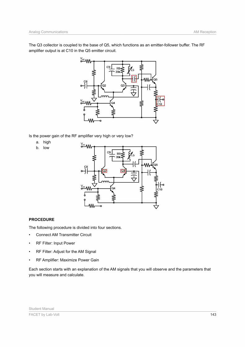
The Q3 collector is coupled to the base of Q5, which functions as an emitter-follower buffer. The RF
a. high
b. low
PROCEDURE
The following procedure is divided into four sections.
• Connect AM Transmitter Circuit
• RF Filter: Input Power
• RF Filter: Adjust for the AM Signal
•
Each section starts with an explanation of the AM signals that you will observe and the parameters that
you will measure and calculate.
Student Manual
144 FACET by Lab-Volt
AM Reception Analog Communications
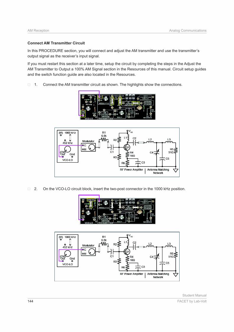
Connect AM Transmitter Circuit
In this PROCEDURE section, you will connect and adjust the AM transmitter and use the transmitter’s
output signal as the receiver’s input signal.
If you must restart this section at a later time, setup the circuit by completing the steps in the Adjust the
AM Transmitter to Output a 100% AM Signal section in the Resources of this manual. Circuit setup guides
and the switch function guide are also located in the Resources.
Connect the AM transmitter circuit as shown. The highlights show the connections.
On the VCO-LO circuit block, insert the two-post connector in the 1000 kHz position.
Student Manual
FACET by Lab-Volt 145
Analog Communications AM Reception
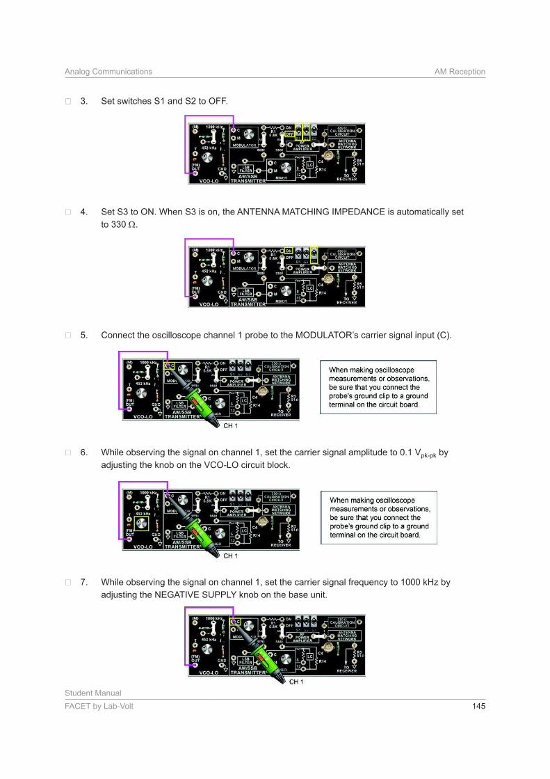
Set switches S1 and S2 to OFF.
Set S3 to ON. When S3 is on, the ANTENNA MATCHING IMPEDANCE is automatically set
to 330 .
Connect the oscilloscope channel 1 probe to the MODULATOR’s carrier signal input (C).
While observing the signal on channel 1, set the carrier signal amplitude to 0.1 Vpk-pk by
adjusting the knob on the VCO-LO circuit block.
While observing the signal on channel 1, set the carrier signal frequency to 1000 kHz by
adjusting the NEGATIVE SUPPLY knob on the base unit.
Student Manual
146 FACET by Lab-Volt
AM Reception Analog Communications
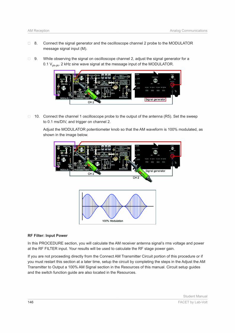
Connect the signal generator and the oscilloscope channel 2 probe to the MODULATOR
message signal input (M).
While observing the signal on oscilloscope channel 2, adjust the signal generator for a
0.1 Vpk-pk, 2 kHz sine wave signal at the message input of the MODULATOR.
Connect the channel 1 oscilloscope probe to the output of the antenna (R5). Set the sweep
Adjust the MODULATOR potentiometer knob so that the AM waveform is 100% modulated, as
shown in the image below.
RF Filter: Input Power
In this PROCEDURE section, you will calculate the AM receiver antenna signal’s rms voltage and power
at the RF FILTER input. Your results will be used to calculate the RF stage power gain.
If you are not proceeding directly from the Connect AM Transmitter Circuit portion of this procedure or if
you must restart this section at a later time, setup the circuit by completing the steps in the Adjust the AM
Transmitter to Output a 100% AM Signal section in the Resources of this manual. Circuit setup guides
and the switch function guide are also located in the Resources.
Student Manual
FACET by Lab-Volt 147
Analog Communications AM Reception
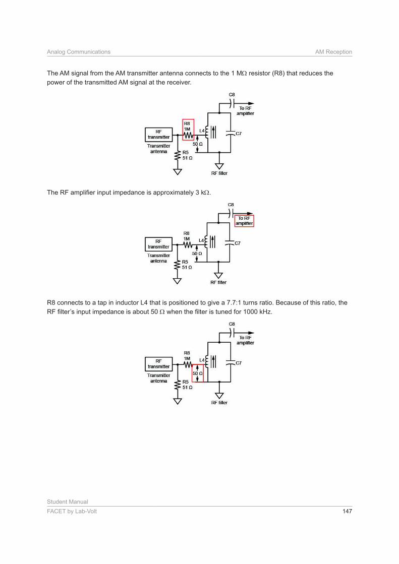
The AM signal from the AM transmitter antenna connects to the 1 M resistor (R8) that reduces the
power of the transmitted AM signal at the receiver.
.
R8 connects to a tap in inductor L4 that is positioned to give a 7.7:1 turns ratio. Because of this ratio, the
Student Manual
148 FACET by Lab-Volt
AM Reception Analog Communications
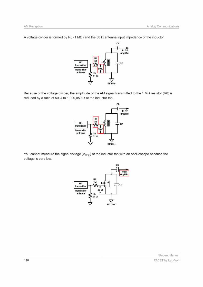
A voltage divider is formed by R8 (1 M ) and the 50 antenna input impedance of the inductor.
Because of the voltage divider, the amplitude of the AM signal transmitted to the 1 M resistor (R8) is
reduced by a ratio of 50 to 1,000,050 at the inductor tap.
You cannot measure the signal voltage [VRF(i)] at the inductor tap with an oscilloscope because the
voltage is very low.
Student Manual
FACET by Lab-Volt 149
Analog Communications AM Reception
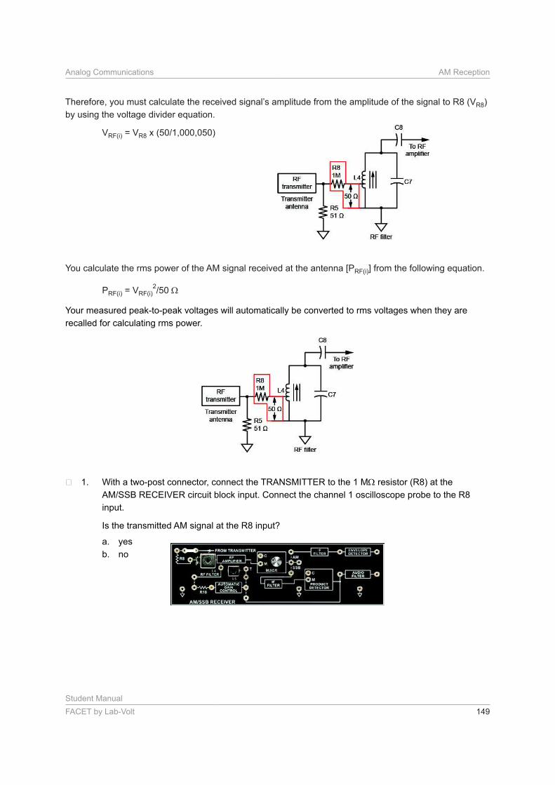
Therefore, you must calculate the received signal’s amplitude from the amplitude of the signal to R8 (VR8)
by using the voltage divider equation.
VRF(i) = VR8
You calculate the rms power of the AM signal received at the antenna [PRF(i)] from the following equation.
PRF(i) = VRF(i)2
Your measured peak-to-peak voltages will automatically be converted to rms voltages when they are
recalled for calculating rms power.
With a two-post connector, connect the TRANSMITTER to the 1 M resistor (R8) at the
Connect the channel 1 oscilloscope probe to the R8
input.
Is the transmitted AM signal at the R8 input?
a. yes
b. no
Student Manual
150 FACET by Lab-Volt
AM Reception Analog Communications
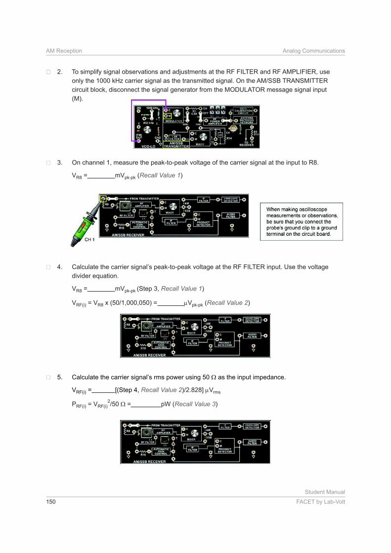
To simplify signal observations and adjustments at the RF FILTER and RF AMPLIFIER, use
circuit block, disconnect the signal generator from the MODULATOR message signal input
(M).
On channel 1, measure the peak-to-peak voltage of the carrier signal at the input to R8.
VR8 = mVpk-pk (Recall Value 1)
Calculate the carrier signal’s peak-to-peak voltage at the RF FILTER input. Use the voltage
divider equation.
VR8 = mVpk-pk (Step 3, Recall Value 1)
VRF(i) = VR8 = Vpk-pk (Recall Value 2)
Calculate the carrier signal’s rms power using 50 as the input impedance.
VRF(i) = [(Step 4, Recall Value 2 Vrms
PRF(i) = VRF(i)2
= pW (Recall Value 3)
Student Manual
FACET by Lab-Volt 151
Analog Communications AM Reception
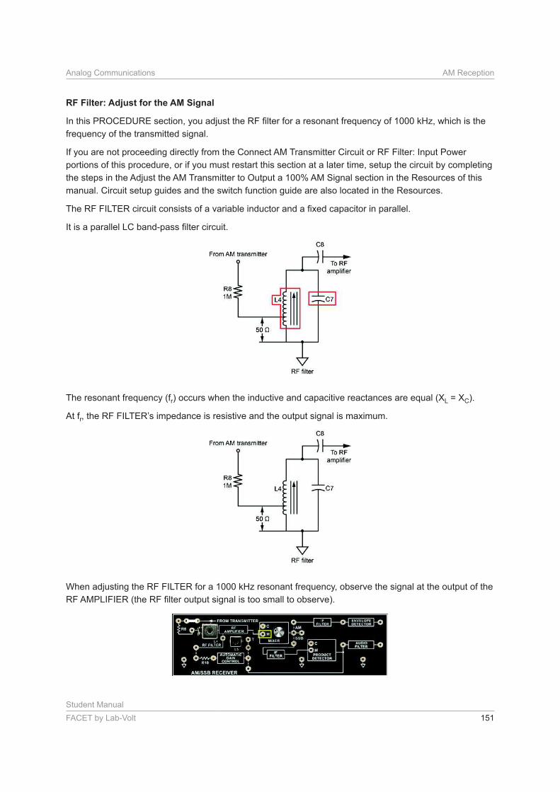
RF Filter: Adjust for the AM Signal
frequency of the transmitted signal.
If you are not proceeding directly from the Connect AM Transmitter Circuit or RF Filter: Input Power
portions of this procedure, or if you must restart this section at a later time, setup the circuit by completing
the steps in the Adjust the AM Transmitter to Output a 100% AM Signal section in the Resources of this
manual. Circuit setup guides and the switch function guide are also located in the Resources.
The resonant frequency (fr) occurs when the inductive and capacitive reactances are equal (XL = XC).
At fr, the RF FILTER’s impedance is resistive and the output signal is maximum.
When adjusting the RF FILTER for a 1000 kHz resonant frequency, observe the signal at the output of the
Student Manual
152 FACET by Lab-Volt
AM Reception Analog Communications
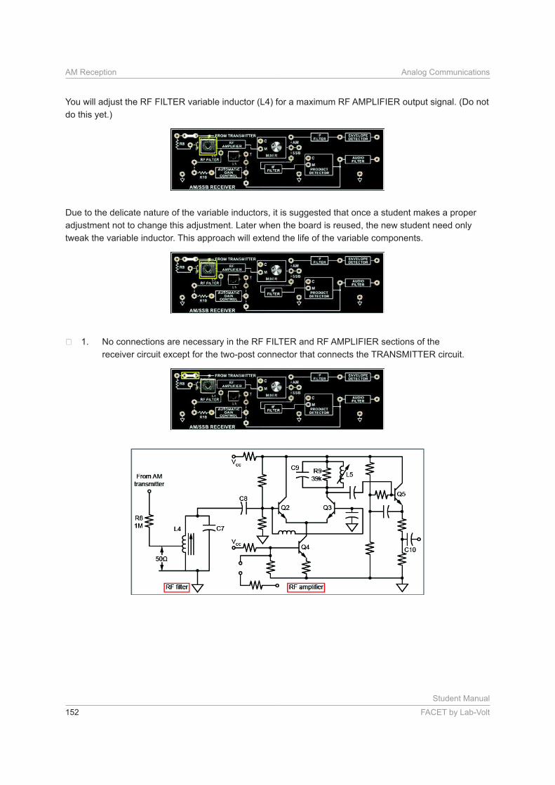
You will adjust the RF FILTER variable inductor (L4) for a maximum RF AMPLIFIER output signal. (Do not
do this yet.)
Due to the delicate nature of the variable inductors, it is suggested that once a student makes a proper
adjustment not to change this adjustment. Later when the board is reused, the new student need only
tweak the variable inductor. This approach will extend the life of the variable components.
No connections are necessary in the RF FILTER and RF AMPLIFIER sections of the
receiver circuit except for the two-post connector that connects the TRANSMITTER circuit.
Student Manual
FACET by Lab-Volt 153
Analog Communications AM Reception
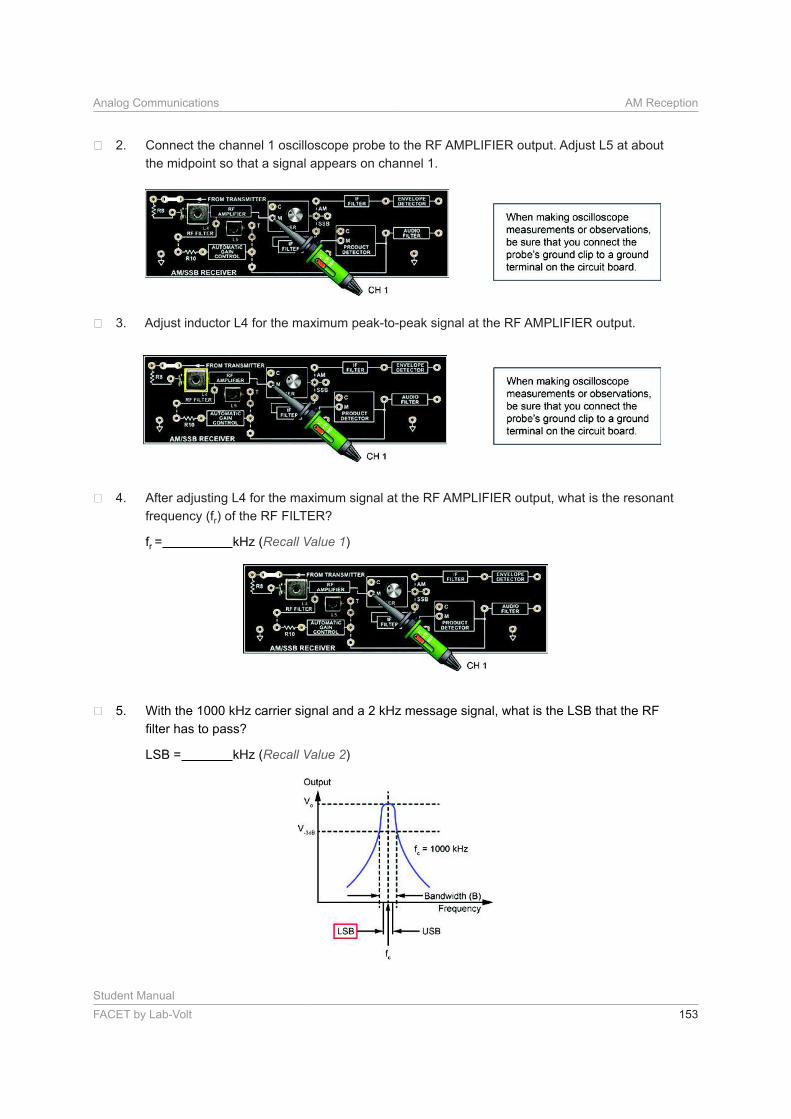
Connect the channel 1 oscilloscope probe to the RF AMPLIFIER output. Adjust L5 at about
the midpoint so that a signal appears on channel 1.
Adjust inductor L4 for the maximum peak-to-peak signal at the RF AMPLIFIER output.
After adjusting L4 for the maximum signal at the RF AMPLIFIER output, what is the resonant
frequency (fr) of the RF FILTER?
fr = kHz (Recall Value 1)
With the 1000 kHz carrier signal and a 2 kHz message signal, what is the LSB that the RF
LSB = kHz (Recall Value 2)
Student Manual
154 FACET by Lab-Volt
AM Reception Analog Communications
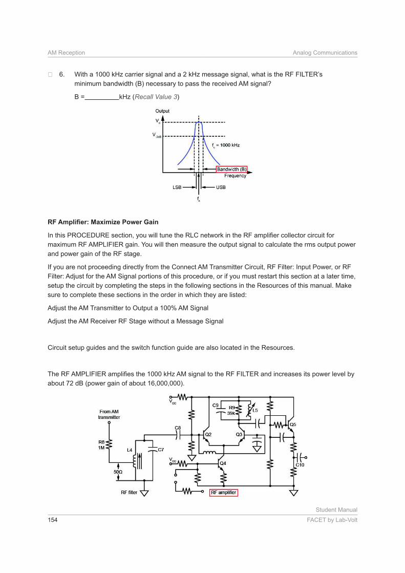
With a 1000 kHz carrier signal and a 2 kHz message signal, what is the RF FILTER’s
minimum bandwidth (B) necessary to pass the received AM signal?
B = kHz (Recall Value 3)
maximum RF AMPLIFIER gain. You will then measure the output signal to calculate the rms output power
and power gain of the RF stage.
If you are not proceeding directly from the Connect AM Transmitter Circuit, RF Filter: Input Power, or RF
Filter: Adjust for the AM Signal portions of this procedure, or if you must restart this section at a later time,
setup the circuit by completing the steps in the following sections in the Resources of this manual. Make
sure to complete these sections in the order in which they are listed:
Adjust the AM Transmitter to Output a 100% AM Signal
Adjust the AM Receiver RF Stage without a Message Signal
Circuit setup guides and the switch function guide are also located in the Resources.
about 72 dB (power gain of about 16,000,000).
Student Manual
FACET by Lab-Volt 155
Analog Communications AM Reception
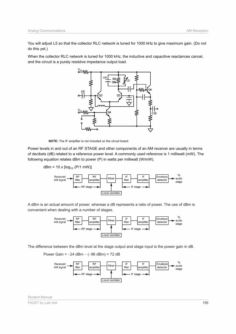
You will adjust L5 so that the collector RLC network is tuned for 1000 kHz to give maximum gain. (Do not
do this yet.)
When the collector RLC network is tuned for 1000 kHz, the inductive and capacitive reactances cancel,
and the circuit is a purely resistive impedance output load.
NOTE:
Power levels in and out of an RF STAGE and other components of an AM receiver are usually in terms
of decibels (dB) related to a reference power level. A commonly used reference is 1 milliwatt (mW). The
dBm = 10 x [log10
A dBm is an actual amount of power, whereas a dB represents a ratio of power. The use of dBm is
convenient when dealing with a number of stages.
The difference between the dBm level at the stage output and stage input is the power gain in dB.
Power Gain = 24 dBm ( 96 dBm) = 72 dB
Student Manual
156 FACET by Lab-Volt
AM Reception Analog Communications
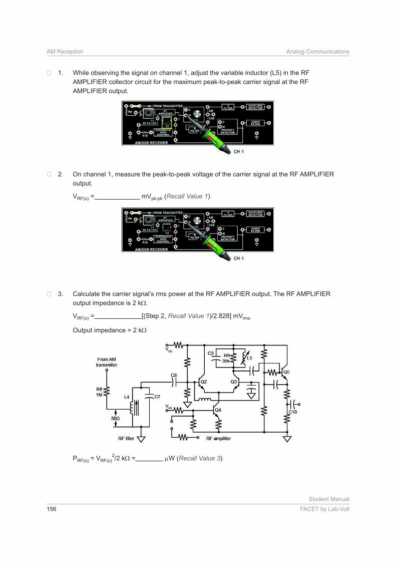
While observing the signal on channel 1, adjust the variable inductor (L5) in the RF
AMPLIFIER collector circuit for the maximum peak-to-peak carrier signal at the RF
AMPLIFIER output.
On channel 1, measure the peak-to-peak voltage of the carrier signal at the RF AMPLIFIER
output.
VRF(o) = mVpk-pk (Recall Value 1)
Calculate the carrier signal’s rms power at the RF AMPLIFIER output. The RF AMPLIFIER
output impedance is 2 k .
VRF(o) = [(Step 2, Recall Value 1 rms
Output impedance = 2 k
PRF(o) = VRF(o)2
= W (Recall Value 3)
Student Manual
FACET by Lab-Volt 157
Analog Communications AM Reception
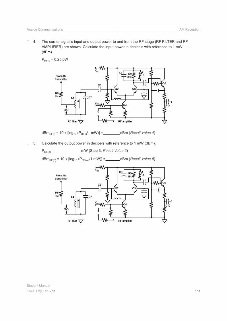
The carrier signal’s input and output power to and from the RF stage (RF FILTER and RF
AMPLIFIER) are shown. Calculate the input power in decibels with reference to 1 mW
(dBm).
PRF(i) = 0.25 pW
dBmRF(i) = 10 x [log10 (PRF(i) dBm (Recall Value 4)
Calculate the output power in decibels with reference to 1 mW (dBm).
PRF(o) = mW (Step 3, Recall Value 3)
dBmRF(o) = 10 x [log10 (PRF(o) dBm (Recall Value 5)
Student Manual
158 FACET by Lab-Volt
AM Reception Analog Communications
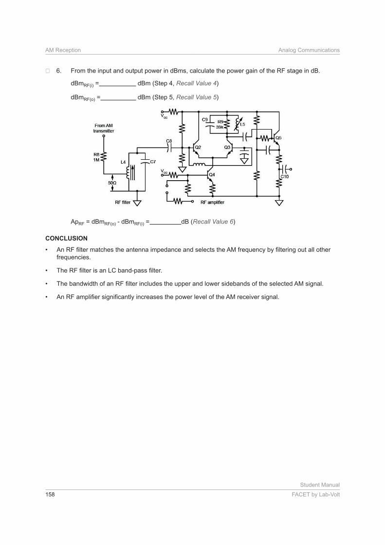
From the input and output power in dBms, calculate the power gain of the RF stage in dB.
dBmRF(i) = dBm (Step 4, Recall Value 4)
dBmRF(o) = dBm (Step 5, Recall Value 5)
ApRF = dBmRF(o) - dBmRF(i) = dB (Recall Value 6)
CONCLUSION
•
frequencies.
•
•
•
Student Manual
FACET by Lab-Volt 159
Analog Communications AM Reception
REVIEW QUESTIONS
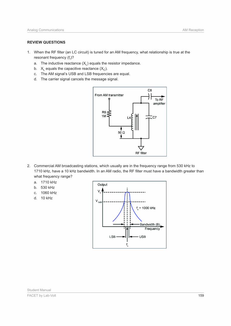
1.
resonant frequency (fr)?
a. The inductive reactance (XL) equals the resistor impedance.
b. XL equals the capacitive reactance (XC).
c. The AM signal’s USB and LSB frequencies are equal.
d. The carrier signal cancels the message signal.
2. Commercial AM broadcasting stations, which usually are in the frequency range from 530 kHz to
what frequency range?
a. 1710 kHz
b. 530 kHz
c. 1060 kHz
d. 10 kHz
Student Manual
160 FACET by Lab-Volt
AM Reception Analog Communications
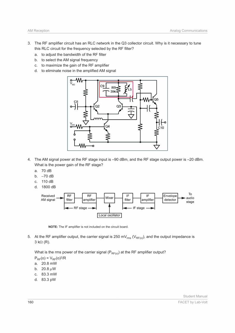
3.
a.
b. to select the AM signal frequency
c.
d.
4. The AM signal power at the RF stage input is –90 dBm, and the RF stage output power is –20 dBm.
What is the power gain of the RF stage?
a. 70 dB
b. –70 dB
c. 110 dB
d. 1800 dB
NOTE:
5. rms (VRF(o)), and the output impedance is
3 k (R).
What is the rms power of the carrier signal (PRF(o)
PRF(o) = VRF(o)2
a. 20.8 mW
b. 20.8 W
c. 83.3 mW
d. 83.3 pW