Embed Size (px)
Citation preview
© Festo Didactic 38542-00 157
When you have completed this exercise, you will be familiar with FM ranging using frequency-modulated continuous-wave (FM-CW) radar.
The Discussion of this exercise covers the following points:
FM-CW radar operation
Signals in the FM-CW radar
Equation of range vs beat frequency
Range resolution and measurement errors
FM-CW radar operation
A simple CW radar continuously transmits an unvarying signal. Although the echo signal may be shifted in frequency due to the Doppler effect, there is no way for the radar to determine how long the signal takes to travel to the target and back.
For a radar to measure the round-trip transit time, the transmitted signal must include some sort of timing marks. By measuring the elapsed time between transmission and reception of the marked signal, the round-trip transit time, and therefore the target range, can be determined.
One way of marking the transmitted signal is to modulate its amplitude. In pulsed radar, amplitude modulation is used to generate discrete pulses of RF energy. The target range is determined by measuring the elapsed time between the transmission and reception of each pulse.
Another way of marking the transmitted signal is to use frequency modulation. In FM-CW radar, the transmitted signal is continuous, but constantly changing in frequency. Because a finite time is required for the signal to travel to the target and back, there will be a difference in instantaneous frequency between the transmitted and received signals. The greater the target range, the greater will be the frequency difference.
Mixing the transmitted and received signals produces a beat frequency equal to the difference between the two frequencies. By measuring the beat frequency, the target range can be determined.
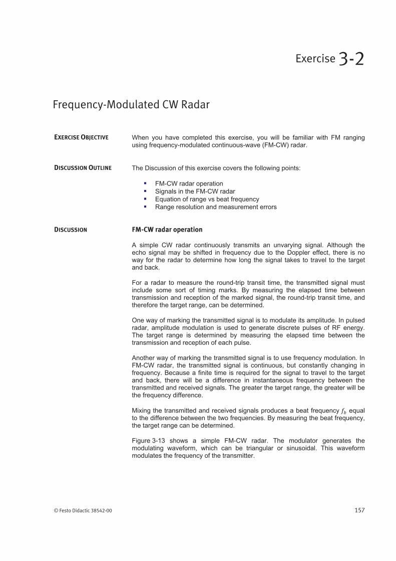
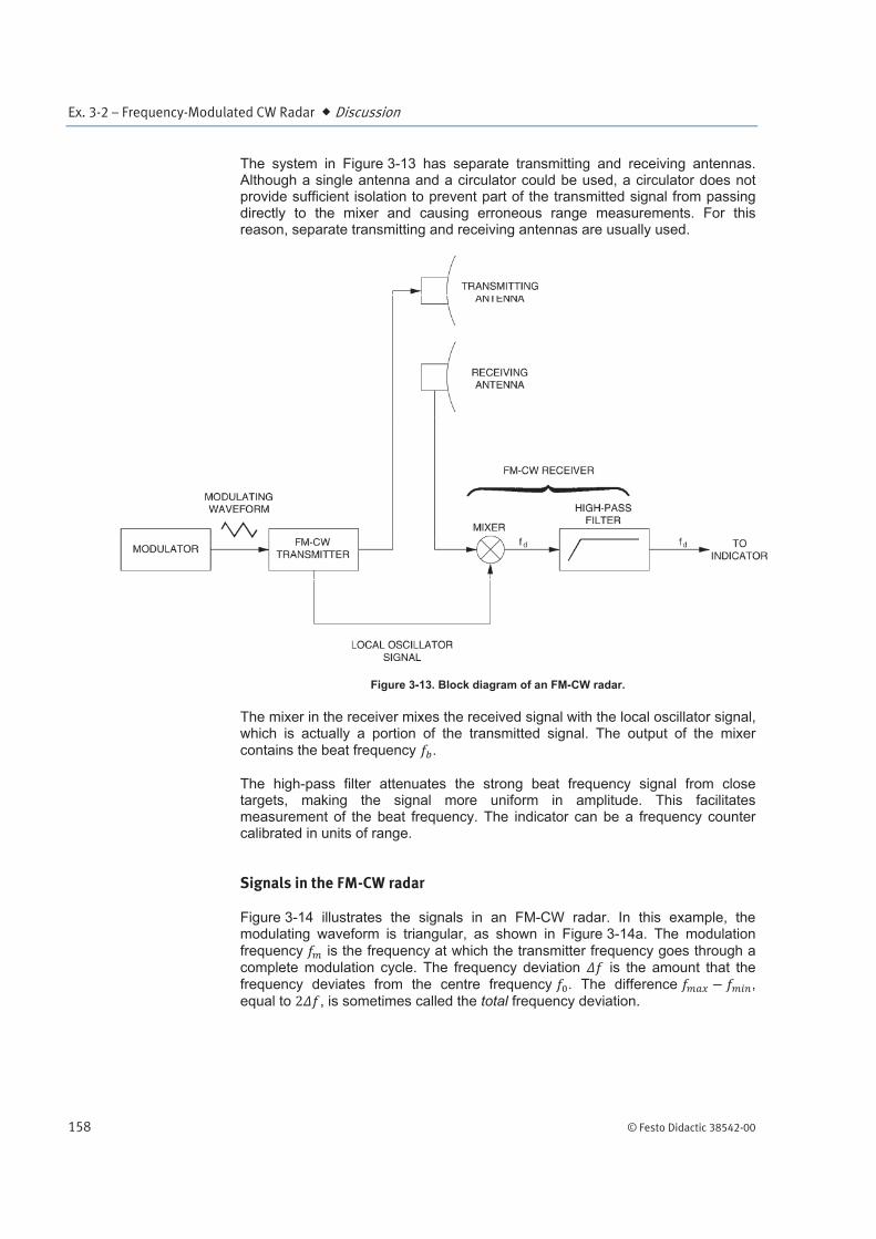
Figure 3-13 shows a simple FM-CW radar. The modulator generates the modulating waveform, which can be triangular or sinusoidal. This waveform modulates the frequency of the transmitter.
Frequency-Modulated CW Radar
Exercise 3-2
EXERCISE OBJECTIVE
DISCUSSION OUTLINE
DISCUSSION
Ex. 3-2 – Frequency-Modulated CW Radar Discussion
158 © Festo Didactic 38542-00
The system in Figure 3-13 has separate transmitting and receiving antennas. Although a single antenna and a circulator could be used, a circulator does not provide sufficient isolation to prevent part of the transmitted signal from passing directly to the mixer and causing erroneous range measurements. For this reason, separate transmitting and receiving antennas are usually used.
Figure 3-13. Block diagram of an FM-CW radar.
The mixer in the receiver mixes the received signal with the local oscillator signal, which is actually a portion of the transmitted signal. The output of the mixer contains the beat frequency .
The high-pass filter attenuates the strong beat frequency signal from close targets, making the signal more uniform in amplitude. This facilitates measurement of the beat frequency. The indicator can be a frequency counter calibrated in units of range.
Signals in the FM-CW radar
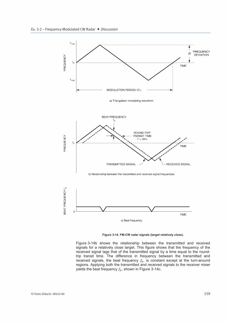
Figure 3-14 illustrates the signals in an FM-CW radar. In this example, the modulating waveform is triangular, as shown in Figure 3-14a. The modulation
frequency is the frequency at which the transmitter frequency goes through a complete modulation cycle. The frequency deviation is the amount that the frequency deviates from the centre frequency . The difference ,
equal to , is sometimes called the total frequency deviation.
Ex. 3-2 – Frequency-Modulated CW Radar Discussion
© Festo Didactic 38542-00 159
Figure 3-14. FM-CW radar signals (target relatively close).
Figure 3-14b shows the relationship between the transmitted and received signals for a relatively close target. This figure shows that the frequency of the received signal lags that of the transmitted signal by a time equal to the round-trip transit time. The difference in frequency between the transmitted and
received signals, the beat frequency , is constant except at the turn-around regions. Applying both the transmitted and received signals to the receiver mixer
yields the beat frequency , shown in Figure 3-14c.
Ex. 3-2 – Frequency-Modulated CW Radar Discussion
160 © Festo Didactic 38542-00
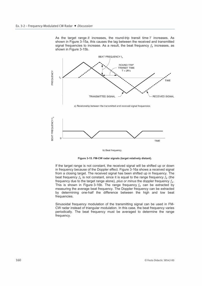
As the target range increases, the round-trip transit time increases. As shown in Figure 3-15a, this causes the lag between the received and transmitted
signal frequencies to increase. As a result, the beat frequency increases, as shown in Figure 3-15b.
Figure 3-15. FM-CW radar signals (target relatively distant).
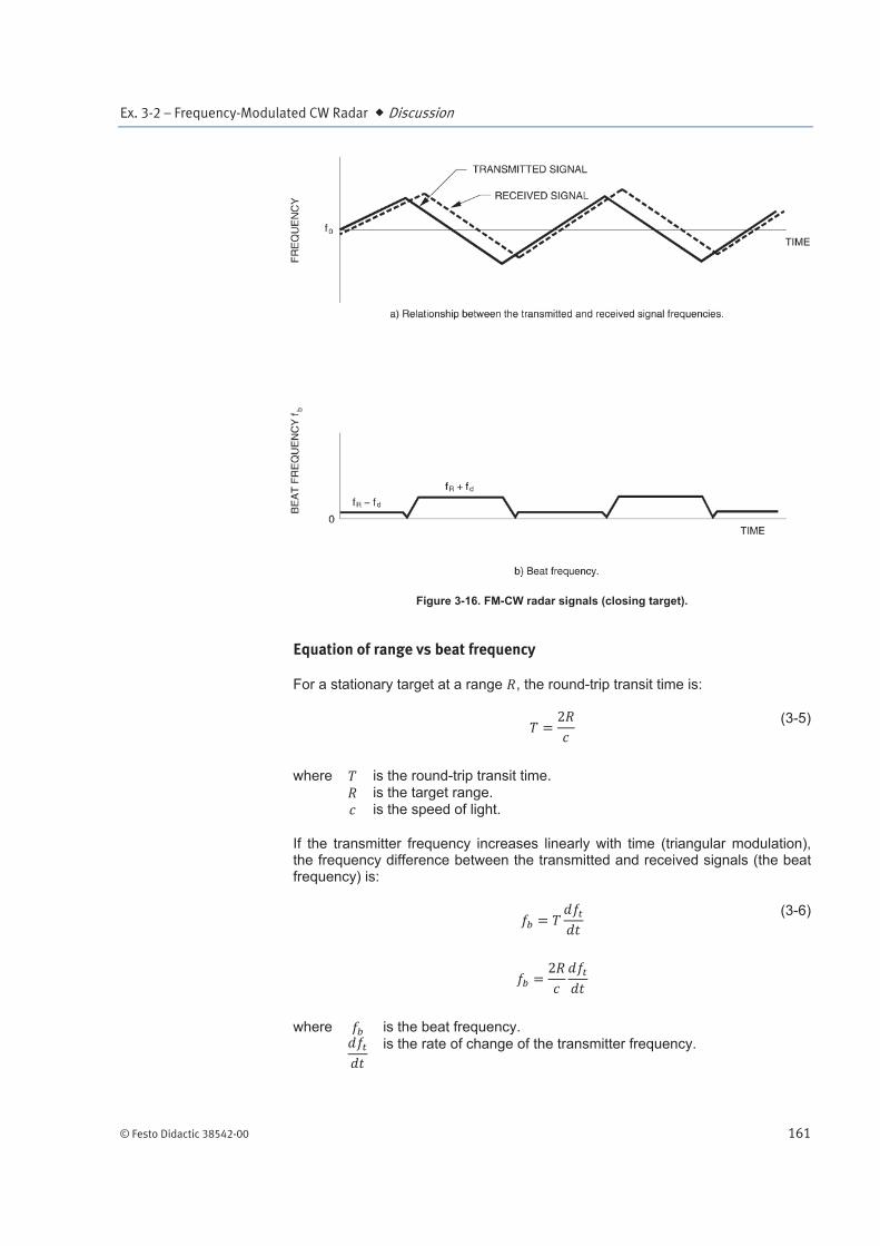
If the target range is not constant, the received signal will be shifted up or down in frequency because of the Doppler effect. Figure 3-16a shows a received signal from a closing target. The received signal has been shifted up in frequency. The
beat frequency is not constant, since it is equal to the range frequency (the frequency due to the target range alone), plus or minus the doppler frequency . This is shown in Figure 3-16b. The range frequency can be extracted by measuring the average beat frequency. The Doppler frequency can be extracted by determining one-half the difference between the high and low beat frequencies.
Sinusoidal frequency modulation of the transmitting signal can be used in FM-CW radar instead of triangular modulation. In this case, the beat frequency varies periodically. The beat frequency must be averaged to determine the range frequency.
Ex. 3-2 – Frequency-Modulated CW Radar Discussion
© Festo Didactic 38542-00 161
Figure 3-16. FM-CW radar signals (closing target).
Equation of range vs beat frequency
For a stationary target at a range , the round-trip transit time is:
(3-5)
where is the round-trip transit time. is the target range. is the speed of light.
If the transmitter frequency increases linearly with time (triangular modulation), the frequency difference between the transmitted and received signals (the beat frequency) is:
(3-6)
where is the beat frequency.
is the rate of change of the transmitter frequency.
Ex. 3-2 – Frequency-Modulated CW Radar Discussion
162 © Festo Didactic 38542-00
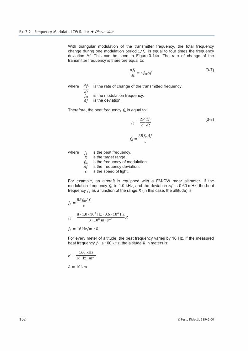
With triangular modulation of the transmitter frequency, the total frequency
change during one modulation period is equal to four times the frequency deviation f. This can be seen in Figure 3-14a. The rate of change of the transmitter frequency is therefore equal to:
(3-7)
where
is the rate of change of the transmitted frequency.
is the modulation frequency.
is the deviation.
Therefore, the beat frequency is equal to:
(3-8)
where is the beat frequency. is the target range.
is the frequency of modulation. is the frequency deviation. is the speed of light.
For example, an aircraft is equipped with a FM-CW radar altimeter. If the
modulation frequency is 1.0 kHz, and the deviation is 0.60 mHz, the beat frequency as a function of the range (in this case, the altitude) is:
For every meter of altitude, the beat frequency varies by 16 Hz. If the measured
beat frequency is 160 kHz, the altitude in meters is:
Ex. 3-2 – Frequency-Modulated CW Radar Discussion
© Festo Didactic 38542-00 163
Range resolution and measurement errors
The range resolution of a radar is the ability to distinguish between closely spaced targets along the same line of sight from the antenna. With FM ranging,
the range resolution depends on the accuracy with which the beat frequency can be measured. This in turn depends on the bandwidth B of the frequency modulation, where B = 2 f.
(3-9)
This is exactly the same relationship between range resolution and bandwidth as with pulsed radar.
A number of factors can introduce measurement errors in an FM-CW radar. The lengths of cables or waveguides connecting the various components introduce an error known as the residual path-length error. In Figure 3-13, the length of the signal path from the transmitter to the transmitting antenna, and from the receiving antenna to the mixer, should ideally be equal to the length of the path of the local oscillator signal. If these two signal path lengths are not equal, as is usually the case, a target at zero range will not produce a zero beat frequency, and all range measurements will be erroneous.
To take into consideration this error, Equation (3-8) becomes:
(3-10)
where is the beat frequency. is the frequency of modulation. is the frequency deviation.
is the speed of light. is the measured target range.
is the residual path-length error. is the actual target range.
When very short ranges are being measured, this residual path-length error is not negligible, and must be compensated for. Fortunately, it is constant for a given system and can be simply subtracted from the measured range to find the actual range.
Some other possible sources of error are uncontrolled variations in transmitter frequency, modulation frequency, or frequency deviation, undesired reflections caused by impedance mismatches, leakage of the transmitted signal directly to the receiver, and double bounce signals.
Ex. 3-2 – Frequency-Modulated CW Radar Procedure Outline
164 © Festo Didactic 38542-00
The Procedure is divided into the following sections:
Setting up the FM-CW radar
Qualitative observation of the FM-CW radar output signal
Beat frequency versus the modulating frequency and frequency deviation
The residual path-length error
Relationship between the beat frequency fb and range R
Setting up the FM-CW radar
In this section, you will set up an FM-CW radar using a separate transmitting and receiving antenna. The block diagram of the system you will use is shown in Figure 3-18. You will observe the signal at the CONTROL VOLTAGE MONITOR OUTPUT of the Radar Transmitter and the effect the FREQUENCY and DEVIATION controls of the FREQUENCY MODULATION section have on this signal.
1. The main elements of the Radar Training System, that is the antenna and its pedestal, the target table and the training modules, must be set up properly before beginning this exercise. Refer to Appendix B of this manual for setting up the Radar Training System, if this is not done yet.
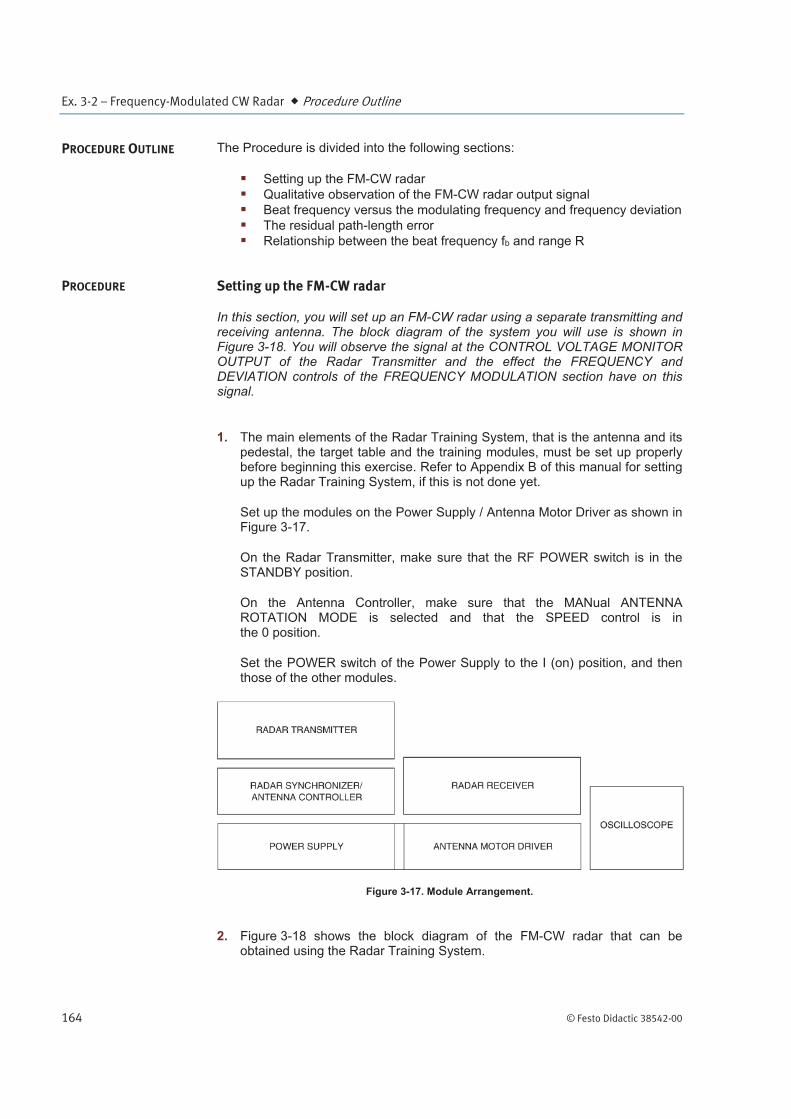
Set up the modules on the Power Supply / Antenna Motor Driver as shown in Figure 3-17.
On the Radar Transmitter, make sure that the RF POWER switch is in the STANDBY position.
On the Antenna Controller, make sure that the MANual ANTENNA ROTATION MODE is selected and that the SPEED control is in the 0 position.
Set the POWER switch of the Power Supply to the I (on) position, and then those of the other modules.
Figure 3-17. Module Arrangement.
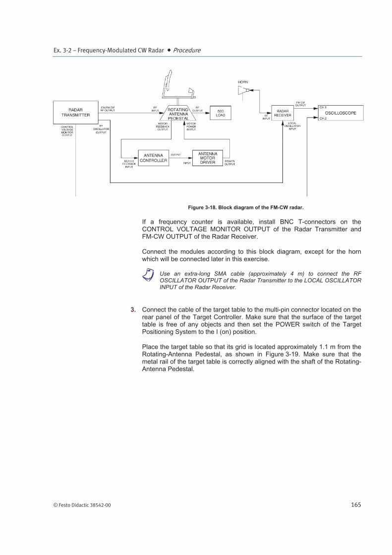
2. Figure 3-18 shows the block diagram of the FM-CW radar that can be obtained using the Radar Training System.
PROCEDURE OUTLINE
PROCEDURE
Ex. 3-2 – Frequency-Modulated CW Radar Procedure
© Festo Didactic 38542-00 165
Figure 3-18. Block diagram of the FM-CW radar.
If a frequency counter is available, install BNC T-connectors on the CONTROL VOLTAGE MONITOR OUTPUT of the Radar Transmitter and FM-CW OUTPUT of the Radar Receiver.
Connect the modules according to this block diagram, except for the horn which will be connected later in this exercise.
a Use an extra-long SMA cable (approximately 4 m) to connect the RF OSCILLATOR OUTPUT of the Radar Transmitter to the LOCAL OSCILLATOR INPUT of the Radar Receiver.
3. Connect the cable of the target table to the multi-pin connector located on the rear panel of the Target Controller. Make sure that the surface of the target table is free of any objects and then set the POWER switch of the Target Positioning System to the I (on) position.
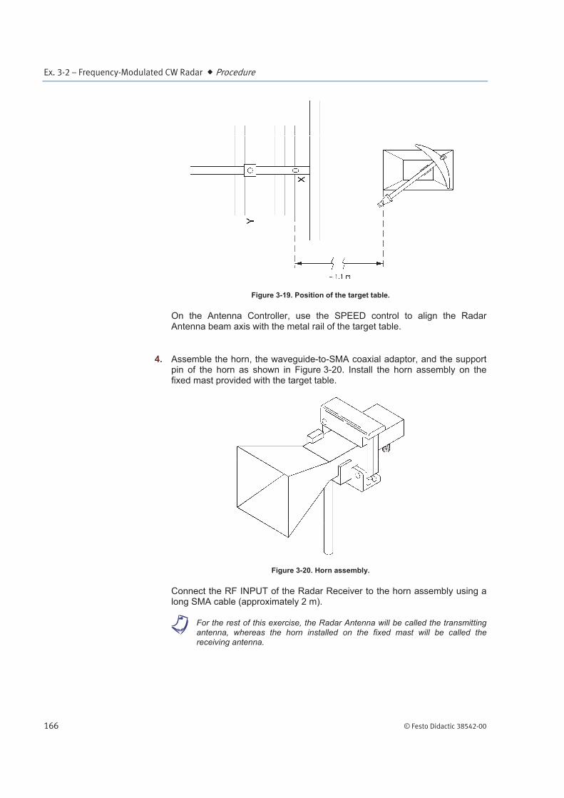
Place the target table so that its grid is located approximately 1.1 m from the Rotating-Antenna Pedestal, as shown in Figure 3-19. Make sure that the metal rail of the target table is correctly aligned with the shaft of the Rotating-Antenna Pedestal.
Ex. 3-2 – Frequency-Modulated CW Radar Procedure
166 © Festo Didactic 38542-00
Figure 3-19. Position of the target table.
On the Antenna Controller, use the SPEED control to align the Radar Antenna beam axis with the metal rail of the target table.
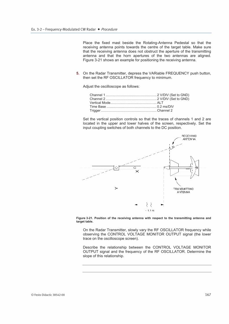
4. Assemble the horn, the waveguide-to-SMA coaxial adaptor, and the support pin of the horn as shown in Figure 3-20. Install the horn assembly on the fixed mast provided with the target table.
Figure 3-20. Horn assembly.
Connect the RF INPUT of the Radar Receiver to the horn assembly using a long SMA cable (approximately 2 m).
a For the rest of this exercise, the Radar Antenna will be called the transmitting antenna, whereas the horn installed on the fixed mast will be called the receiving antenna.
Ex. 3-2 – Frequency-Modulated CW Radar Procedure
© Festo Didactic 38542-00 167
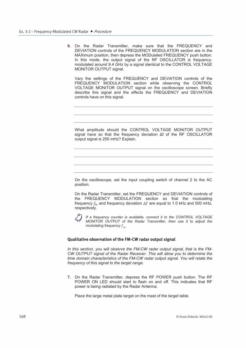
Place the fixed mast beside the Rotating-Antenna Pedestal so that the receiving antenna points towards the centre of the target table. Make sure that the receiving antenna does not obstruct the aperture of the transmitting antenna and that the horn apertures of the two antennas are aligned. Figure 3-21 shows an example for positioning the receiving antenna.
5. On the Radar Transmitter, depress the VARiable FREQUENCY push button, then set the RF OSCILLATOR frequency to minimum.
Adjust the oscilloscope as follows:
Channel 1 ...................................................... 2 V/DIV (Set to GND) Channel 2 ...................................................... 2 V/DIV (Set to GND) Vertical Mode ................................................. ALT Time Base ..................................................... 0.2 ms/DIV Trigger ........................................................... Channel 2
Set the vertical position controls so that the traces of channels 1 and 2 are located in the upper and lower halves of the screen, respectively. Set the input coupling switches of both channels to the DC position.
Figure 3-21. Position of the receiving antenna with respect to the transmitting antenna and target table.
On the Radar Transmitter, slowly vary the RF OSCILLATOR frequency while observing the CONTROL VOLTAGE MONITOR OUTPUT signal (the lower trace on the oscilloscope screen).
Describe the relationship between the CONTROL VOLTAGE MONITOR OUTPUT signal and the frequency of the RF OSCILLATOR. Determine the slope of this relationship.
Ex. 3-2 – Frequency-Modulated CW Radar Procedure
168 © Festo Didactic 38542-00
6. On the Radar Transmitter, make sure that the FREQUENCY and DEVIATION controls of the FREQUENCY MODULATION section are in the MAXimum position, then depress the MODulated FREQUENCY push button. In this mode, the output signal of the RF OSCILLATOR is frequency-modulated around 9.4 GHz by a signal identical to the CONTROL VOLTAGE MONITOR OUTPUT signal.
Vary the settings of the FREQUENCY and DEVIATION controls of the FREQUENCY MODULATION section while observing the CONTROL VOLTAGE MONITOR OUTPUT signal on the oscilloscope screen. Briefly describe this signal and the effects the FREQUENCY and DEVIATION controls have on this signal.
What amplitude should the CONTROL VOLTAGE MONITOR OUTPUT signal have so that the frequency deviation f of the RF OSCILLATOR output signal is 250 mHz? Explain.
On the oscilloscope, set the input coupling switch of channel 2 to the AC position.
On the Radar Transmitter, set the FREQUENCY and DEVIATION controls of the FREQUENCY MODULATION section so that the modulating frequency and frequency deviation are equal to 1.0 kHz and 500 mHz, respectively.
a If a frequency counter is available, connect it to the CONTROL VOLTAGE MONITOR OUTPUT of the Radar Transmitter, then use it to adjust the modulating frequency .
Qualitative observation of the FM-CW radar output signal
In this section, you will observe the FM-CW radar output signal, that is the FM-CW OUTPUT signal of the Radar Receiver. This will allow you to determine the time domain characteristics of the FM-CW radar output signal. You will relate the frequency of this signal to the target range.
7. On the Radar Transmitter, depress the RF POWER push button. The RF POWER ON LED should start to flash on and off. This indicates that RF power is being radiated by the Radar Antenna.
Place the large metal plate target on the mast of the target table.
Ex. 3-2 – Frequency-Modulated CW Radar Procedure
© Festo Didactic 38542-00 169
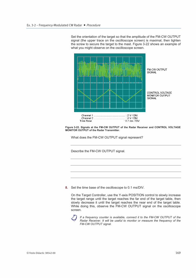
Set the orientation of the target so that the amplitude of the FM-CW OUTPUT signal (the upper trace on the oscilloscope screen) is maximal, then tighten the screw to secure the target to the mast. Figure 3-22 shows an example of what you might observe on the oscilloscope screen.
Figure 3-22. Signals at the FM-CW OUTPUT of the Radar Receiver and CONTROL VOLTAGE MONITOR OUTPUT of the Radar Transmitter.
What does the FM-CW OUTPUT signal represent?
Describe the FM-CW OUTPUT signal.
8. Set the time base of the oscilloscope to 0.1 ms/DIV.
On the Target Controller, use the Y-axis POSITION control to slowly increase the target range until the target reaches the far end of the target table, then slowly decrease it until the target reaches the near end of the target table. While doing this, observe the FM-CW OUTPUT signal on the oscilloscope screen.
a If a frequency counter is available, connect it to the FM-CW OUTPUT of the Radar Receiver. It will be useful to monitor or measure the frequency of the FM-CW OUTPUT signal.
Ex. 3-2 – Frequency-Modulated CW Radar Procedure
170 © Festo Didactic 38542-00
Describe the relationship between the target range and the FM-CW OUTPUT signal.
Explain the reason for this relationship.
Beat frequency versus the modulating frequency and frequency deviation
In this section, you will vary the modulating frequency and frequency deviation of the Radar Transmitter, while observing the effect on the FM-CW OUTPUT signal of the Radar Receiver. This will allow you to determine the relationship between the beat frequency , and the modulating frequency and frequency deviation .
9. On the Target Controller, depress the POSITION MODE push button, then use the Y-axis POSITION control to place the target approximately in the centre of the target table grid.
Using the oscilloscope or the frequency counter, determine the frequency of
the FM-CW OUTPUT signal (beat frequency ). Note the result below.
If you use the oscilloscope to determine the beat frequency , count the number of cycles of the FM-CW OUTPUT signal occurring during one cycle of the CONTROL VOLTAGE MONITOR OUTPUT signal (cycle of the triangular modulating signal). Divide the number of cycles you counted by the
period of the triangular modulating signal to obtain the beat frequency .
Beat frequency ( 1.0 kHz, 500 mHz) kHz
10. On the Radar Transmitter, slowly vary the DEVIATION control of the FREQUENCY MODULATION section to decrease the frequency deviation f until it is equal to 250 mHz. While doing this, observe the FM-CW OUTPUT signal on the oscilloscope screen.
Describe what happens as the frequency deviation f decreases.
Ex. 3-2 – Frequency-Modulated CW Radar Procedure
© Festo Didactic 38542-00 171
Using the oscilloscope or the frequency counter, determine the beat
frequency . Note the result below.
Beat frequency ( 1.0 kHz, 250 mHz) kHz
Describe the relationship between the beat frequency and frequency
deviation . Explain.
11. Set the time base of the oscilloscope to 0.2 ms/DIV.
On the Radar Transmitter, set the DEVIATION control of the FREQUENCY MODULATION section so that the frequency deviation f is equal to 500 mHz. The beat frequency should be approximately equal to that measured in step 9 of this exercise.
Slowly vary the FREQUENCY control of the FREQUENCY MODULATION section to decrease the modulating frequency until it is equal to 0.5 kHz. While doing this, observe the FM-CW OUTPUT signal on the oscilloscope screen.
Describe what happens as the modulating frequency decreases.
Using the oscilloscope or the frequency counter, determine the beat
frequency . Note the result below.
Beat frequency ( 0.5 kHz, 500 mHz) kHz
Describe the relationship between the beat frequency and modulating frequency . Explain.
Ex. 3-2 – Frequency-Modulated CW Radar Procedure
172 © Festo Didactic 38542-00
The residual path-length error
In this section, you will place a target as near as possible to the horn ( 0 m) of the transmitting antenna, and observe that the beat frequency is not null. You will measure this frequency, that is the residual beat frequency. Knowing the modulating frequency and frequency deviation , you will calculate the residual path-length error. You will then determine the parts of your FM-CW radar which are the major contributors to the residual path-length error.
12. On the Radar Transmitter, set the FREQUENCY control of the FREQUENCY MODULATION section so that the modulating frequency is equal
to 1.0 kHz. The beat frequency should be approximately equal to that measured in step 9 of this exercise.
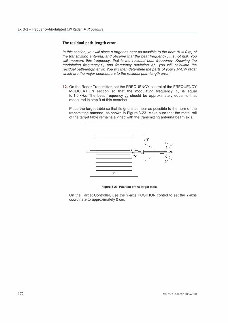
Place the target table so that its grid is as near as possible to the horn of the transmitting antenna, as shown in Figure 3-23. Make sure that the metal rail of the target table remains aligned with the transmitting antenna beam axis.
Figure 3-23. Position of the target table.
On the Target Controller, use the Y-axis POSITION control to set the Y-axis coordinate to approximately 0 cm.
Ex. 3-2 – Frequency-Modulated CW Radar Procedure
© Festo Didactic 38542-00 173
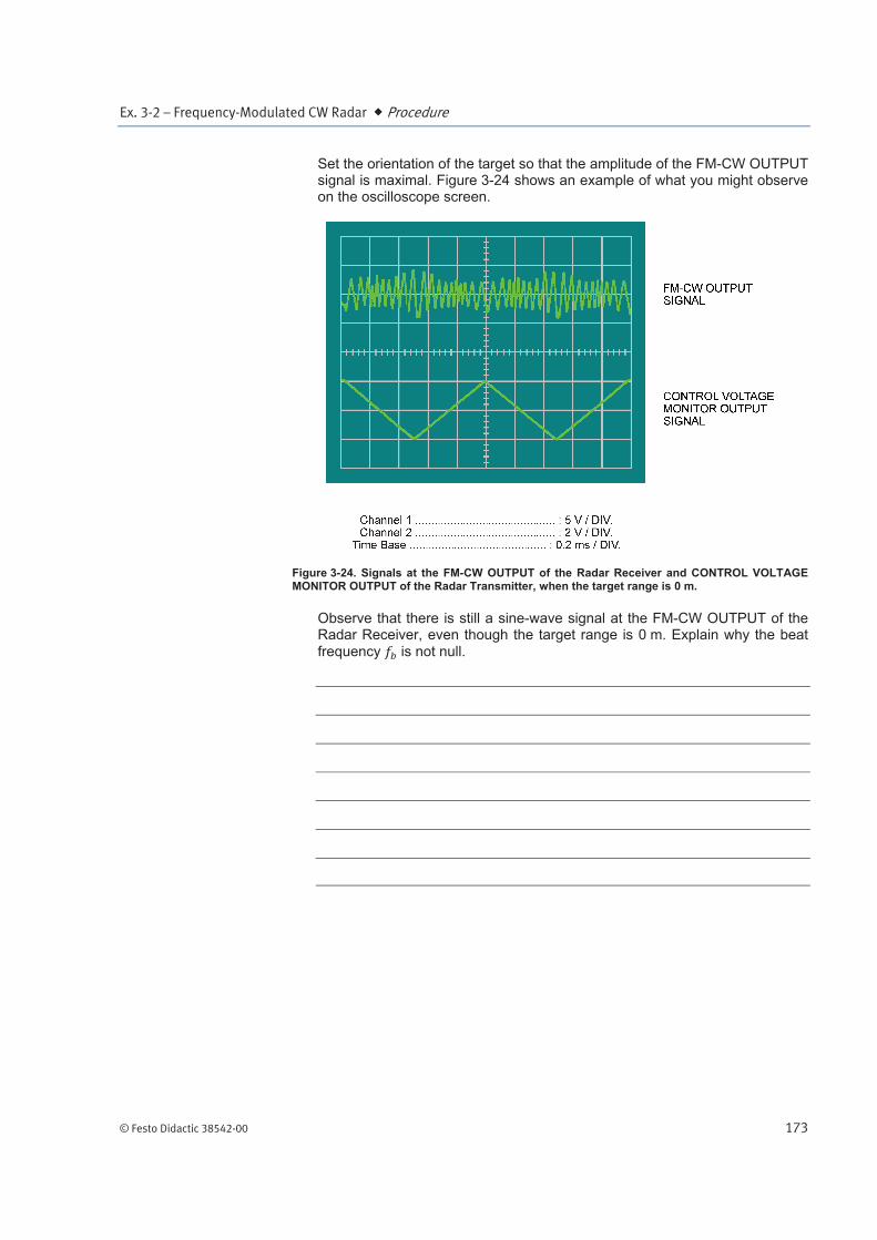
Set the orientation of the target so that the amplitude of the FM-CW OUTPUT signal is maximal. Figure 3-24 shows an example of what you might observe on the oscilloscope screen.
Figure 3-24. Signals at the FM-CW OUTPUT of the Radar Receiver and CONTROL VOLTAGE MONITOR OUTPUT of the Radar Transmitter, when the target range is 0 m.
Observe that there is still a sine-wave signal at the FM-CW OUTPUT of the Radar Receiver, even though the target range is 0 m. Explain why the beat frequency is not null.
Ex. 3-2 – Frequency-Modulated CW Radar Procedure
174 © Festo Didactic 38542-00
13. Using the oscilloscope or the frequency counter, determine the beat
frequency of the FM-CW OUTPUT signal. For convenience, this frequency will be called the residual beat frequency, and will be noted as (residual) in equations. Note the result below.
Residual beat frequency ( 1.0 kHz, 500 mHz) kHz
Using this result and knowing that the modulating frequency and frequency deviation f are equal to 1 kHz and 500 mHz, respectively, calculate the residual path-length error.
From this result, determine the parts of your FM-CW radar which are the major contributors to the residual path-length error.
Relationship between the beat frequency fb and range R
In this section, you will measure the beat frequency for various target ranges. Knowing the modulating frequency , the frequency deviation , and the residual path-length error, you will calculate the target range related to each beat frequency measured. You will compare the real target ranges with the calculated ones, and plot the relationship between the beat frequency and the
range .
14. On the Target Controller, use the Y-axis POSITION control to move the target so that the range which separates it from the back of the transmitting antenna horn is approximately equal to 0.5 m. Use the measuring tape to determine the target range, if necessary.

Ex. 3-2 – Frequency-Modulated CW Radar Procedure
© Festo Didactic 38542-00 175
Set the orientation of the target so that the amplitude of the FM-CW OUTPUT signal is maximal.
Using the oscilloscope or the frequency counter, determine the beat
frequency . Note the result in the first row of the BEAT FREQUENCY column of Table 3-2.
Table 3-2. Target range versus the beat frequency ( 1 kHz, 500 mHz).
ACTUAL TARGET RANGE
BEAT FREQUENCY
CALCULATED TARGET RANGE
m kHz m
0.5
1.0
2.0
3.0
Moving the target table, and using the Target Controller and measuring tape, successively set the target range to the other values given in the ACTUAL TARGET RANGE R column of Table 3-2.
For each target range, make sure that the target remains aligned with the transmitting antenna beam axis, and that the orientation of the target provides a maximum amplitude signal at the FM-CW OUTPUT of the Radar Receiver. Then, use the oscilloscope or the frequency counter to determine the beat frequency , and note the result in the appropriate row of the BEAT
FREQUENCY column of Table 3-2.
15. Knowing that the modulating frequency and the frequency deviation are equal to 1 kHz and 500 mHz, respectively, use the residual path-length error calculated in step 13 to calculate the target ranges related to the beat
frequencies noted in Table 3-2. Note the results in the CALCULATED TARGET RANGE column of Table 3-2.
Compare the calculated target ranges with the actual ones.
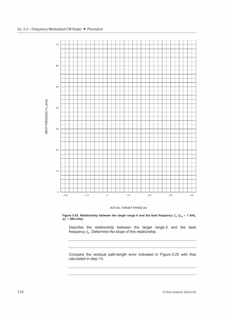
Using the results noted in the ACTUAL TARGET RANGE R and BEAT
FREQUENCY columns of Table 3-2, plot the relationship between the beat frequency and the target range in Figure 3-25. Extrapolate the relationship to the ACTUAL TARGET RANGE axis, and indicate the residual path-length error along this axis.
Ex. 3-2 – Frequency-Modulated CW Radar Procedure
176 © Festo Didactic 38542-00
Figure 3-25. Relationship between the target range and the beat frequency ( 1 kHz,
500 mHz).
Describe the relationship between the target range and the beat frequency . Determine the slope of this relationship.
Compare the residual path-length error indicated in Figure 3-25 with that calculated in step 13.
Ex. 3-2 – Frequency-Modulated CW Radar Conclusion
© Festo Didactic 38542-00 177
16. On the Radar Transmitter, make sure that the RF POWER switch is in the STANDBY position. The RF POWER STANDBY LED should be lit. Place all POWER switches in the O (off) position and disconnect all cables and accessories.
In this exercise, you saw that the echo signal of a fixed target, obtained with an FM-CW radar, is a sine-wave signal with some discontinuities. You verified that the frequency of this signal, which is called beat frequency, is proportional to the
target range. You determined that the beat frequency is directly proportional to the modulating frequency and frequency deviation .
You saw that there is a difference, inherent to the FM-CW radar, between the path lengths travelled by the RF signals received at the RF INPUT and LOCAL
OSCILLATOR INPUT of the Radar Receiver. This causes the beat frequency to be not null when the target range is equal to 0 m, and introduces a constant error, the residual path-length error, in all range measurements. You verified that this error can be subtracted from the measured range to determine the actual range.
1. Why can an unmodulated CW radar not determine target range?
2. Explain the basic principle of FM-CW radar.
3. How can the range be determined using FM ranging if the target is moving?
CONCLUSION
REVIEW QUESTIONS
Ex. 3-2 – Frequency-Modulated CW Radar Review Questions
178 © Festo Didactic 38542-00
4. Find the target range for an FM-CW radar with a detected beat frequency of 100 kHz. The frequency modulation is triangular with a frequency deviation of 50 mHz and a modulation frequency of 100 Hz. The residual path-length error is 5.0 m.
5. On what depends the range resolution of an FM-CW radar?