Embed Size (px)
Citation preview
Exeter®
Surgical Technique
Orthopaedics
V40™ Stem Cement-in-Cement
Exeter V40 StemCement-in-Cement Surgical Technique
Table of Contents
Indications and Contraindications ...............................................2
Warnings and Precautions ............................................................2
Introduction .....................................................................................3
Operative Technique ......................................................................4
Instrument and Implant Listing ...................................................7
This publication sets forth detailed recommended procedures for using Stryker Orthopaedics devices and instruments. It offers guidance that you should heed,but, as with any such technical guide, each surgeon must consider the particular needs of each patient and make appropriate adjustments when and as required.
Indications for Exeter V40
The indications for use in total hip arthroplasty include:• Non-inflammatory degenerative joint disease, including
osteoarthritis and avascular necrosis.• Rheumatoid arthritis.• Correction of functional deformity.• Revision procedures where other treatments or devices
have failed.• Treatment of nonunion, femoral neck and trochanteric
fractures of the proximal femur with head involvement that are unmanageable using other techniques.
Contraindications for Exeter V40
1. Active infection or suspected latent infection in or about the hip joint.
2. Bone stock that is inadequate for support or fixation of the prosthesis.
3. Skeletal immature.
4. Any mental or neuromuscular disorder that would create an unacceptable risk of prosthesis instability, prosthesis fixation failure, or complications in postoperative care.
Warnings and Precautions
See implant package insert for warnings, precautions, adverse effects and other essential product information.
Before using instrumentation, verify:
• Instruments have been properly disassembled prior to cleaning and sterilisation
• Instruments have been properly assembled post sterilisation
• Instruments have maintained design integrity
• Proper size configuration is available
For Instructions for Cleaning, Sterilization, Inspection and Maintenance of Orthopaedic Medical Devices, refer to LSTPI-B.
INTRODUCTION
3
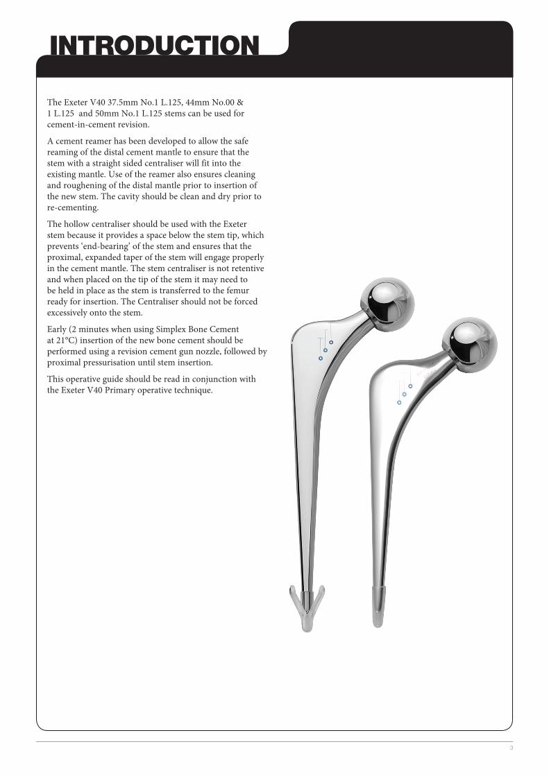
The Exeter V40 37.5mm No.1 L.125, 44mm No.00 & 1 L.125 and 50mm No.1 L.125 stems can be used for cement-in-cement revision.
A cement reamer has been developed to allow the safe reaming of the distal cement mantle to ensure that the stem with a straight sided centraliser will fit into the existing mantle. Use of the reamer also ensures cleaning and roughening of the distal mantle prior to insertion of the new stem. The cavity should be clean and dry prior to re-cementing.
The hollow centraliser should be used with the Exeter stem because it provides a space below the stem tip, which pre vents ‘end-bearing’ of the stem and ensures that the proximal, expanded taper of the stem will engage properly in the cement mantle. The stem centraliser is not retentive and when placed on the tip of the stem it may need to be held in place as the stem is transferred to the femur ready for insertion. The Centraliser should not be forced excessively onto the stem.
Early (2 minutes when using Simplex Bone Cement at 21°C) insertion of the new bone cement should be performed using a revision cement gun nozzle, followed by proximal pressurisation until stem insertion.
This operative guide should be read in conjunction with the Exeter V40 Primary operative technique.
1
4
OPERATIVE TECHNIQUE
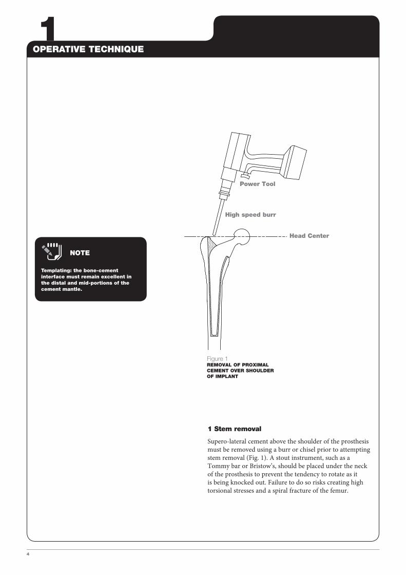
1 Stem removal
Supero-lateral cement above the shoulder of the prosthesis must be removed using a burr or chisel prior to attempting stem removal (Fig. 1). A stout instrument, such as a Tommy bar or Bristow’s, should be placed under the neck of the prosthesis to prevent the tendency to rotate as it is being knocked out. Failure to do so risks creating high torsional stresses and a spiral fracture of the femur.
High speed burr
Head Center
Power Tool
Figure 1REMOVAL OF PROXIMAL CEMENT OVER SHOULDER OF IMPLANT
Templating: the bone-cement interface must remain excellent in the distal and mid-portions of the cement mantle.
NOTE
2/3/4/5OPERATIVE TECHNIQUE
5
Power Tool
Reamer
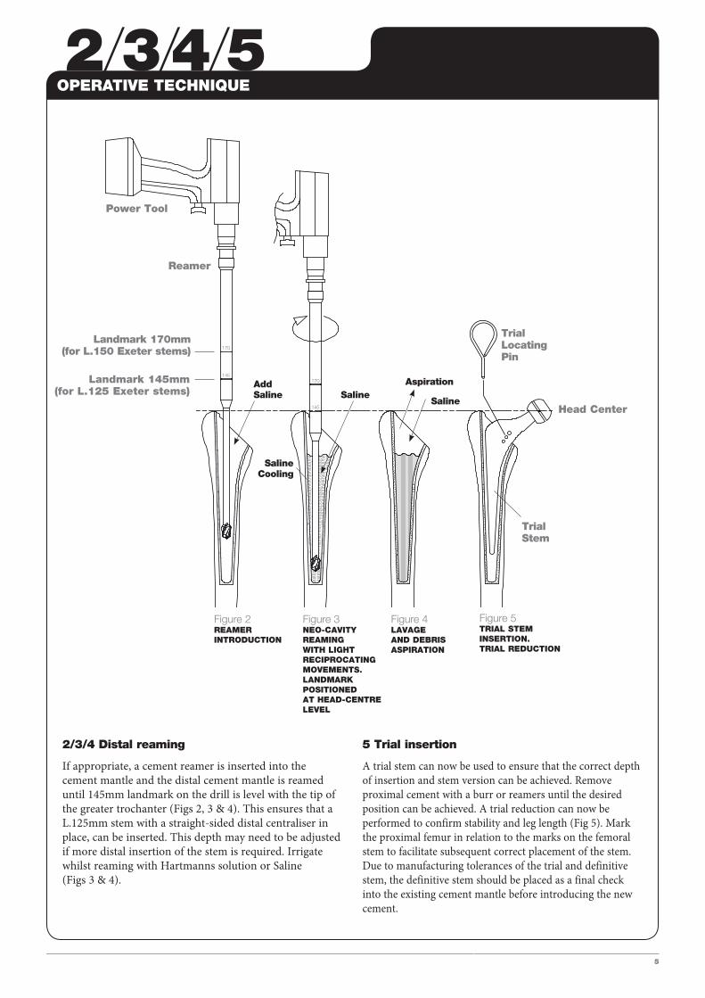
2/3/4 Distal reaming
If appropriate, a cement reamer is inserted into the cement mantle and the distal cement mantle is reamed until 145mm landmark on the drill is level with the tip of the greater trochanter (Figs 2, 3 & 4). This ensures that a L.125mm stem with a straight-sided distal centraliser in place, can be inserted. This depth may need to be adjusted if more distal insertion of the stem is required. Irrigate whilst reaming with Hartmanns solution or Saline (Figs 3 & 4).
5 Trial insertion
A trial stem can now be used to ensure that the correct depth of insertion and stem version can be achieved. Remove proximal cement with a burr or reamers until the desired position can be achieved. A trial reduction can now be performed to confirm stability and leg length (Fig 5). Mark the proximal femur in relation to the marks on the femoral stem to facilitate subsequent correct placement of the stem. Due to manufacturing tolerances of the trial and definitive stem, the definitive stem should be placed as a final check into the existing cement mantle before introducing the new cement.
Add Saline
TrialLocating Pin
SalineCooling
Saline
Trial Stem
Saline
Aspiration
Landmark 170mm (for L.150 Exeter stems)
Landmark 145mm (for L.125 Exeter stems)
Figure 2REAMER INTRODUCTION
Figure 3NEO-CAVITYREAMING WITH LIGHT RECIPROCATINGMOVEMENTS.LANDMARK POSITIONEDAT HEAD-CENTRE LEVEL
Figure 4LAVAGEAND DEBRISASPIRATION
Figure 5TRIAL STEMINSERTION.TRIAL REDUCTION
Head Center
6/7/8
6
OPERATIVE TECHNIQUE
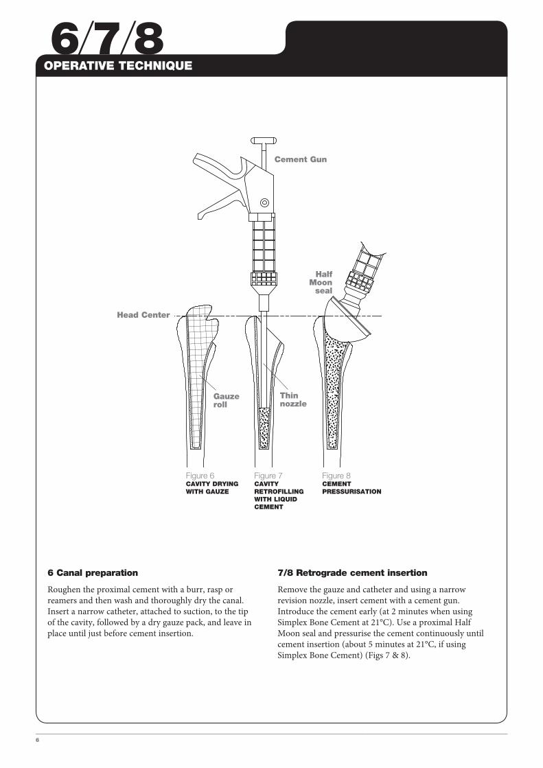
6 Canal preparation
Roughen the proximal cement with a burr, rasp or reamers and then wash and thoroughly dry the canal. Insert a narrow catheter, attached to suction, to the tip of the cavity, followed by a dry gauze pack, and leave in place until just before cement insertion.
7/8 Retrograde cement insertion
Remove the gauze and catheter and using a narrow revision nozzle, insert cement with a cement gun. Introduce the cement early (at 2 minutes when using Simplex Bone Cement at 21°C). Use a proximal Half Moon seal and pressurise the cement continuously until cement insertion (about 5 minutes at 21°C, if using Simplex Bone Cement) (Figs 7 & 8).
Figure 6CAVITY DRYING WITH GAUZE
Figure 7CAVITY RETROFILLING WITH LIQUID CEMENT
Figure 8CEMENT PRESSURISATION
Cement Gun
Half Moon
seal
Gauze roll
Thin nozzle
Head Center
9/10
7
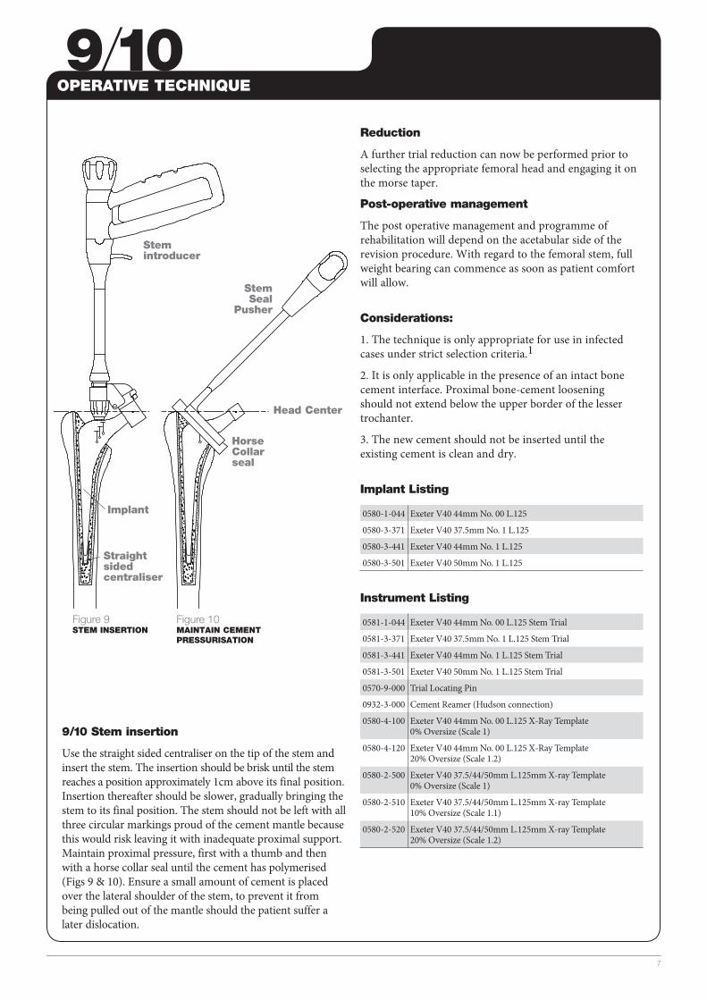
Figure 9STEM INSERTION
Figure 10MAINTAIN CEMENT PRESSURISATION
Stem Seal
Pusher
Stem introducer
Horse Collar seal
Implant
Straight sided centraliser
Head Center
Reduction
A further trial reduction can now be performed prior to selecting the appropriate femoral head and engaging it on the morse taper.
Post-operative management
The post operative management and programme of rehabilitation will depend on the acetabular side of the revision procedure. With regard to the femoral stem, full weight bearing can commence as soon as patient comfort will allow.
Considerations:
1. The technique is only appropriate for use in infected cases under strict selection criteria.1
2. It is only applicable in the presence of an intact bone cement interface. Proximal bone-cement loosening should not extend below the upper border of the lesser trochanter.
3. The new cement should not be inserted until the existing cement is clean and dry.
Implant Listing
0580-1-044 Exeter V40 44mm No. 00 L.125
0580-3-371 Exeter V40 37.5mm No. 1 L.125
0580-3-441 Exeter V40 44mm No. 1 L.125
0580-3-501 Exeter V40 50mm No. 1 L.125
Instrument Listing
0581-1-044 Exeter V40 44mm No. 00 L.125 Stem Trial
0581-3-371 Exeter V40 37.5mm No. 1 L.125 Stem Trial
0581-3-441 Exeter V40 44mm No. 1 L.125 Stem Trial
0581-3-501 Exeter V40 50mm No. 1 L.125 Stem Trial
0570-9-000 Trial Locating Pin
0932-3-000 Cement Reamer (Hudson connection)
0580-4-100 Exeter V40 44mm No. 00 L.125 X-Ray Template 0% Oversize (Scale 1)
0580-4-120 Exeter V40 44mm No. 00 L.125 X-Ray Template 20% Oversize (Scale 1.2)
0580-2-500 Exeter V40 37.5/44/50mm L.125mm X-ray Template 0% Oversize (Scale 1)
0580-2-510 Exeter V40 37.5/44/50mm L.125mm X-ray Template 10% Oversize (Scale 1.1)
0580-2-520 Exeter V40 37.5/44/50mm L.125mm X-ray Template 20% Oversize (Scale 1.2)
OPERATIVE TECHNIQUE
9/10 Stem insertion
Use the straight sided centraliser on the tip of the stem and insert the stem. The insertion should be brisk until the stem reaches a position approximately 1cm above its final position. Insertion thereafter should be slower, gradually bringing the stem to its final position. The stem should not be left with all three circular markings proud of the cement mantle because this would risk leaving it with inadequate proximal support. Maintain proximal pressure, first with a thumb and then with a horse collar seal until the cement has polymerised (Figs 9 & 10). Ensure a small amount of cement is placed over the lateral shoulder of the stem, to prevent it from being pulled out of the mantle should the patient suffer a later dislocation.
References
1. Morley JR, Blake SM, Hubble MJW, Timperley AJ, Gie GA, Howell JR. Preservation of the original femoral cement mantle during the management of infected cemented total hip arthroplasty by two-stage revision. J Bone Joint Surg [Br]2012: 94B: 322-7.
Stryker325 Corporate DriveMahwah, NJ 07430t: 201 831 5000 www.stryker.com
A surgeon must always rely on his or her own professional clinical judgment when deciding whether to use a particular product when treating a particular patient. Stryker does not dispense medical advice and recommends that surgeons be trained in the use of any particular product before using it in surgery.
The information presented is intended to demonstrate the breadth of Stryker product offerings. A surgeon must always refer to the package insert, product label and/or instructions for use before using any Stryker product. The products depicted are CE marked according to the Medical Device Directive 93/42/EEC. Products may not be available in all markets because product availability is subject to the regulatory and/or medical practices in individual markets. Please contact your Stryker representative if you have questions about the availability of Stryker products in your area.
Stryker Corporation or its divisions or other corporate affiliated entities own, use or have applied for the following trademarks or service marks: Exeter, Simplex, Stryker, Stryker Orthopaedics, V40. All other trademarks are trademarks of their respective owners or holders.
EXETER-SP-4MT/TC 08/14
Copyright © 2014 Stryker