Embed Size (px)
Citation preview

BCEAS'
Generator Interconnection System Impact Study for
SCE&G V.C. Summer Nuclear #2
Prepared for: SCE&G Nuclear Group
July 5, 2007
Prepared by: SCE&G Transmission Planning
Exhibit Q-1 (Exhibit No. _____ (HCY-1)) Page 1 of 22

TABLE OF CONTENTS
General Discussion........................................................................ Page 3
I. Generator Information ............................................................... Page 5 II. Transmission Studies................................................................ Page 5
a. Power Flow Analysis ..................................................... Page 5 b. Short Circuit Analysis .................................................... Page 6 c. Stability Analysis ........................................................... Page 6
III. Required Interconnection Facilities ......................................... Page 17
IV. Engineering Design & Cost ..................................................... Page 19
a. Engineering Single Line Layout ................................... Page 19 b. Transmission & Substation Cost.................................. Page 21
V. Adjustments to the VC Summer #2 Interconnection Plan ....... Page 22
Exhibit Q-1 (Exhibit No. _____ (HCY-1)) Page 2 of 22

3
Generator Interconnection System Impact Study for
SCE&G V.C. Summer Nuclear #2
A Generator Interconnection System Impact Study is an extension of the previous Generation Interconnection Feasibility Study, and is a detailed study of the SCE&G transmission system considering the full output of the proposed new generation. The System Impact Study includes a full test of the NERC Reliability Standards Table 1 and the SCE&G Internal Transmission Planning Criteria. General Discussion The SCE&G Nuclear Group has applied for interconnection of a new 1375 MVA nuclear generator near the existing V.C. Summer site. This new generator would be jointly owed by SCE&G and Santee Cooper, SCE&G would own 55% and Santee Cooper would own the remaining 45%. In this study Santee Cooper’s portion of the generator output was represented as delivered to the Santee Cooper system. In addition to this Interconnection System Impact Study, SCE&G Transmission Planning participated in a joint study with Southern Company, Santee Cooper, Duke Energy and other interconnected transmission providers to evaluate the effect of this generator and other planned generators in the region. Results of this joint study indicated no unacceptable interaction between these planned generators or the identified associated transmission expansion. In the future, SCE&G Transmission Planning will periodically review the results of this Interconnection System Impact Study to determine if the recommended expansion remains valid. The previously completed Feasibility Study recommended the following transmission line improvements:
1. Construct a VC Summer #2-Killian 230kV line with B1272 conductor • (add 230kV terminal at Killian)
2. Construct a VC Summer #2-Lake Murray 230kV line with B1272 conductor • (add 230kV terminal at Lake Murray)
3. Construct a VC Summer #2-VC Summer (existing) Bus #2 230kV line with B1272 conductor
• (add 230kV terminal at VC Summer #1 Bus #2) 4. Construct a VC Summer #2-VC Summer (existing) Bus #3 230kV line with B1272
conductor • (add 230kV terminal at VC Summer #1 Bus #3)
5. Upgrade the existing Denny Terrace-Lyles 230kV line to B1272 6. Upgrade the existing Parr-VC Summer #1 230kV line to B1272 7. Upgrade the existing Parr-VC Summer #2 230kV line to B1272 8. Add a 3rd 230/115kV 336 MVA auto transformer at Lake Murray 9. Add a 3rd 230/115kV 336 MVA auto transformer at Denny Terrace
Exhibit Q-1 (Exhibit No. _____ (HCY-1)) Page 3 of 22

4
10. Upgrade the existing Saluda-McMeekin 115kV line to B1272 11. Upgrade the existing Lake Murray-McMeekin 115kV line to B1272 12. Upgrade the existing Lake Murray-Saluda 115kV to with B1272
In addition, it will be necessary to construct a new 230kV generator substation at the proposed site using a breaker-and-a-half design with seven 230kV terminals.
1. One - for the generator step up transformer 2. One - for station service 3. One - for the new 230kV line to the existing V. C. Summer 230kV bus #2 4. One - for the new 230kV line to the existing V. C. Summer 230kV bus #3 5. One - for the new 230kV line to Lake Murray 6. One - for the new 230kV line to Killian 7. One - for the new 230kV line to Santee Cooper
A total of eleven 230kV breakers are needed at the new generator substation for this design.
To resolve overstressed conditions of several 230kV and 115kV breakers as described in the Short Circuit Analysis section, Transmission Planning recommends replacing the following breakers with higher interrupting capability breakers:
Location Voltage Breaker # VC Summer 230 8722 VC Summer 230 8732 VC Summer 230 8742 VC Summer 230 8772 VC Summer 230 8792 VC Summer 230 8832 VC Summer 230 8842 VC Summer 230 8852 VC Summer 230 8892 VC Summer 230 8912 VC Summer 230 8942 Parr 230 6402 Parr 230 6412 Parr 230 6422 Parr 230 6432 Parr 230 6442 Saluda Hydro 115 562 McMeekin 115 1051 McMeekin 115 2051 Edenwood 115 2712 Edenwood 115 3672 Edenwood 115 3682 Denny Terrace 115 8032 Denny Terrace 115 8042 Denny Terrace 115 8092
Exhibit Q-1 (Exhibit No. _____ (HCY-1)) Page 4 of 22

5
The report will be presented as follows:
I. Generation Information II. Transmission Studies
A. Power Flow Analysis B. Short Circuit Analysis C. Stability Analysis
III. Required Interconnection Facilities IV. Engineering Design & Cost
I. Generator Information The generator design consists of a single nuclear unit and one step-up transformer. The generator unit will have a maximum gross MVA output capacity of 1,375 MVA and a maximum continuous net MW of 1,165 MW. The generator design consists of the following information:
MVA – gross: 1375 MW – net: 1165 Power Factor: between .90 and 1.05 Voltage: 22kV Speed: 1800 rpm X’d-sat.: 0.465 PU; X’’d-sat.: 0.325 PU X2-sat.: 0.320 PU; X0: 0.237 PU
II. Transmission Studies
A. Power Flow Analysis Since the completion of the Generation Interconnection Feasibility Study, modifications were made to the 230kV generator substation layout and the arrangement of lines connecting to the existing V.C. Summer substation and the proposed V.C. Summer substation. These changes resulted in the proposed retirement of the Parr 230kV substation. The original improvements along with these proposed modifications were modeled and Transmission Planning has run more detailed power flow analysis of the SCE&G transmission system to include a full test of the NERC Reliability Standards Table 1 and the SCE&G Internal Transmission Planning Criteria. This analysis shows the following overload condition due to the additional generation:
Exhibit Q-1 (Exhibit No. _____ (HCY-1)) Page 5 of 22

6
Overloaded Facility
Emergency Rating (MVA)
Loading (%)
Contingency
Lake Murray-Lyles 115kV line 123 101 Outage of Denny Terrace 230kV Bus #1 and #2 (Category C-9)
Transmission Planning recommends that this contingency event be mitigated by installing a 2nd bus tie breaker at the Denny Terrace 230kV bus. B. Short Circuit Analysis
The previously complete feasibility study indicated sixteen 230kV breakers and nine 115kV breakers were overstressed due to the additional generation at V. C. Summer and must be replaced. However, five of these 230kV breakers are at Parr 230kV substation and because of the proposed retirement of the Parr 230kV substation, these five breaker replacements are no longer required. Additionally, two 230kV breakers are eliminated at the VC Summer #1 Substation with the new line arrangement. Transmission Planning now recommends that nine 230kV breakers and nine 115kV breakers be replaced as listed in the recommendations section of this report. C. Stability Analysis 1. Overview of Stability Analysis. The stability study of the connection of the V.C. Summer #2 AP1000 generator to the SCE&G and SCPSA transmission systems assessed the ability of this generator to remain in synchronism following selected transmission system contingencies. Also reviewed were the adequacy of damping of generation/transmission oscillations and the impact of the proposed generator on the stability performance of other system generators. System voltage responses were examined for indications of voltage instability. In addition, generator frequency responses and the effects of protective system performance were evaluated. For the system peak load cases, the nearby V.C. Summer #1 generator was simulated as switched off except for where noted as otherwise. In addition, the 230kV transmission line connecting the V.C. Summer #2 generator switchyard to SCPSA’s Pomaria substation was switched out. These outages were simulated in order to account for the possibility that major generation and transmission could be out of service during the operation of the connecting facility. Power flow studies showed that these were the generation and transmission outages that resulted in the greatest impact on the reactive output of the V.C. Summer #2 generator. Rotor angle responses of the V.C. Summer #2 generator were simulated in order to determine if angular instability could result from likely contingencies. Generator frequency deviations were examined in order to determine if generator frequency protection could result in generator tripping. The results of the loss of the V.C.
Exhibit Q-1 (Exhibit No. _____ (HCY-1)) Page 6 of 22
7
Summer #2 generator were examined in order to determine if any resulting underfrequency relay operations would lead to system load shedding. Finally, the effects of each contingency on the V.C. Summer #2 230kV switchyard bus were examined along with voltages at the existing V.C. Summer #1 230kV and 115kV Offsite Power Supply buses to determine if the voltage requirements of the Offsite Power Supply buses were violated. Generator response plots are not included but are available for review upon request. An initial 30 second steady state simulation for the selected connection configuration was performed in order to establish that steady state conditions existed prior to fault conditions. The simulation of each contingency repeated the steady state condition for 1 second prior to introducing permanent fault conditions so that the responses could be compared to the initial steady state condition. In order to determine the effects on all system generators, contingencies were simulated under system peak load conditions and system valley load conditions. Contingencies were selected in order to satisfy each of four categories as specified by NERC Reliability Standards TPL-001 through TPL-004. As a companion to this study, SCPSA has performed a study of this generator interconnection and has determined that the NERC Reliability Standards are satisfied for its system. An Executive Summary of the SCPSA study of generator rotor angle responses to contingencies on its system follows the results of the SCE&G stability analysis. Although not included in this report, a stability study of this interconnection was also performed for the VCS #2 & VCS #3 Combined Operating License Application (COLA). The results of that study support the findings of this Interconnection Study. The results of the stability analysis are described in the following sections and are summarized following the detailed results. 2. Results of Peak Load Stability Analysis. A.1. Steady state conditions (NERC Category A condition) The interconnection of the V.C. Summer #2 generator was shown to result in system steady state conditions. Generator rotor angles and frequencies showed no deviations through out the 30 second simulation. The voltage at the V.C. Summer #2 bus remained at 232.3kV during the simulation. The voltages at the V.C. Summer #1 Offsite Power Supply buses were constant at 232.3kV and 117.75kV. A.2. Normal clearing of a three phase fault on the V.C. Summer #2 generator terminal 26kV bus (NERC Category B-1 Contingency) Following a 1 second steady state period, a permanent fault was simulated at the 26Kv side of the V.C. Summer #2 generator step up transformer. This results in the opening of the generator breaker 5 cycles after the appearance of the fault. Since the station service buses are normally served from the 26kV bus, this operation would result in the loss of the station service loads. However, the station fast transfer scheme switches these loads to the switchyard 230kV bus and allows the continued service of these loads. Rotor angle oscillations were moderate and well damped with no indication of angular instability. There was no indication of voltage instability. Likewise, system
Exhibit Q-1 (Exhibit No. _____ (HCY-1)) Page 7 of 22
8
frequency responses were also moderate and well damped with no indication of system underfrequency load shedding or generator under/overfrequency operations. During the application of the fault, the voltage at the V.C. Summer #2 bus dropped to 121.41kV. The V.C. Summer #1 230kV and 115kV Offsite Power Supply bus voltages dropped to 125.06kV and 78.98kV respectively. This allowed the degraded voltage and loss of voltage relay timers to initiate. However, the voltages recovered enough to reset the timers within 1 cycle of the clearing of the fault. Steady state conditions were reestablished with no further system operations. A.3. Delayed clearing of a single line to ground fault on the future V.C. Summer #2 switchyard to the existing V.C. Summer #1 generator switchyard bus #2 (NERC Category C-8 contingency) Since this contingency places a fault near the existing V.C. Summer #1 generator, this unit was modeled as switched on. All local transmission lines were also modeled as in service. Following a 1 second steady state period, a permanent single phase-to-ground fault was simulated at the V.C. Summer #2 end of the V.C. Summer #2 – V.C. Summer #1 230kV transmission line #2. The circuit breaker at the V.C. Summer #1 end of the line was simulated as operating normally. The breaker and a half scheme at the V.C. Summer #2 switchyard cleared the fault following a fault duration of approximately 0.25 seconds. During the application of the fault, the voltage at the V.C. Summer #2 bus dropped to 121.44kV. The V.C. Summer #1 230kV and 115kV Offsite Power Supply bus voltages dropped to 126.94kV and 71.20kV respectively. This allowed the degraded voltage and loss of voltage relay timers to initiate. However, the voltages recovered enough to reset the timers within 1 cycle of the clearing of the fault. Rotor angle oscillations were moderate and were adequately damped with no indication of angular instability. There was no indication of voltage instability. Likewise, system frequency responses were also moderate and adequately damped with no indication of system underfrequency load shedding or generator under/overfrequency operations. Steady state conditions were reestablished with no further system operations.
A.4. Normal clearing of a three phase fault on the existing V.C. Summer #1 generator switchyard bus #1 (NERC Category D-10 contingency) Since this contingency places a fault near the existing V.C. Summer #1 generator, this unit was modeled as switched on. All local transmission lines were also modeled as in service. Following a 1 second steady state period, a permanent single three phase fault was simulated at the V.C. Summer #1 bus #1. Since this is the bus that the V.C. Summer #1 generator is connected to that generator was tripped when the fault was cleared. In addition, in order to prevent the Fairfield Pumped Storage generators from becoming unstable, a Special Protection System will need to be installed at the V.C. Summer #1 switchyard that will trip those units
Exhibit Q-1 (Exhibit No. _____ (HCY-1)) Page 8 of 22

9
as well. The operations to clear the fault and trip the generators will occur within 6 cycles from the appearance of the bus fault. During the application of the fault, the voltage at the V.C. Summer #2 230kV bus dropped to 6.99kV. The V.C. Summer #1 230kV and 115kV Offsite Power Supply bus voltages dropped to 0.00kV and 21.79kV respectively. This allowed the degraded voltage and loss of voltage relay timers to initiate. However, the voltages recovered enough to reset the timers within 14-15 cycles following the appearance of the fault. Rotor angle oscillations were moderate and were adequately damped with no indication of angular instability. There was no indication of voltage instability. Likewise, system frequency responses were also moderate and adequately damped with no indication of system underfrequency load shedding or generator under/overfrequency operations. Steady state conditions were reestablished with no further system operations. 3. Results of Low Load Stability Analysis. A.1. Steady state conditions (NERC Category A condition) The interconnection of the V.C. Summer #2 generator was shown to result in system steady state conditions. Generator rotor angles and frequencies showed no deviations through out the 30 second simulation. The voltage at the V.C. Summer #2 bus remained at 232.3kV during the simulation. The voltages at the V.C. Summer #1 Offsite Power Supply buses were constant at 232.3kV and 116.84kV. A.2. Normal clearing of a three phase fault on the V.C. Summer #2 generator terminal 26kV bus (NERC Category B-1 Contingency) Following a 1 second steady state period, a permanent fault was simulated at the 26Kv side of the V.C. Summer #2 generator step up transformer. This results in the opening of the generator breaker 5 cycles after the appearance of the fault. Since the station service buses are normally served from the 26kV bus, this operation would result in the loss of the station service loads. However, the station fast transfer scheme switches these loads to the switchyard 230kV bus and allows the continued service of these loads. Rotor angle oscillations were small but poorly damped due to the smaller level of synchronizing torque within the system due to the reduced amount of generation on line during system low load conditions. However, the generator rotor angle oscillations were eventually damped and there was no indication of angular instability. There was no indication of voltage instability. Likewise, system frequency responses were also small and poorly damped but with no indication of system underfrequency load shedding or generator under/overfrequency operations. During the application of the fault, the voltage at the V.C. Summer #2 bus dropped to 133.47kV. The V.C. Summer #1 230kV and 115kV Offsite Power Supply bus voltages dropped to 136.00kV and 74.82kV respectively. This allowed the degraded
Exhibit Q-1 (Exhibit No. _____ (HCY-1)) Page 9 of 22
10
voltage and loss of voltage relay timers to initiate. However, the voltages recovered enough to reset the timers within 1 cycle of the clearing of the fault. Steady state conditions were reestablished with no further system operations. A.3. Delayed clearing of a single line to ground fault on the future V.C. Summer #2 switchyard to the existing V.C. Summer #1 generator switchyard bus #2 (NERC Category C-8 contingency) Since this contingency places a fault near the existing V.C. Summer #1 generator, this unit was modeled as switched on. All local transmission lines were also modeled as in service. Following a 1 second steady state period, a permanent single phase-to-ground fault was simulated at the V.C. Summer #2 end of the V.C. Summer #2 – V.C. Summer #1 230kV transmission line #2. The circuit breaker at the V.C. Summer #1 end of the line was simulated as operating normally. The breaker and a half scheme at the V.C. Summer #2 switchyard cleared the fault following a fault duration of approximately 0.25 seconds. During the application of the fault, the voltage at the V.C. Summer #2 bus dropped to 115.83kV. The V.C. Summer #1 230kV and 115kV Offsite Power Supply bus voltages dropped to 121.03kV and 67.65kV respectively. This allowed the degraded voltage and loss of voltage relay timers to initiate. The voltages recovered enough to reset the timers within 2-3 cycles of the clearing of the fault. Rotor angle oscillations were small and were adequately damped with no indication of angular instability. There was no indication of voltage instability. Likewise, system frequency responses were also small and adequately damped with no indication of system underfrequency load shedding or generator under/overfrequency operations. Steady state conditions were reestablished with no further system operations. A.4. Normal clearing of a three phase fault on the existing V.C. Summer #1 generator switchyard bus #1 (NERC Category D-10 contingency)
Since this contingency places a fault near the existing V.C. Summer #1 generator, this unit was modeled as switched on. All local transmission lines were also modeled as in service. Following a 1 second steady state period, a permanent three phase fault was simulated at the V.C. Summer #1 bus #1. Since this is the bus that the V.C. Summer #1 generator is connected to, that generator was tripped when the fault was cleared. In addition, in order to prevent the Fairfield Pumped Storage generators from becoming unstable, a Special Protection System will need to be installed at the V.C. Summer #1 switchyard that will trip those units as well. The operations to clear the fault and trip the generators will occur within 6 cycles from the appearance of the bus fault. During the application of the fault, the voltage at the V.C. Summer #2 230kV bus dropped to 5.89kV. The V.C. Summer #1 230kV and 115kV Offsite Power Supply bus voltages dropped to 0.00kV and 18.19kV respectively. This allowed the degraded voltage and loss of voltage relay timers to initiate. However, the voltages
Exhibit Q-1 (Exhibit No. _____ (HCY-1)) Page 10 of 22

11
recovered enough to reset the timers within 12-17 cycles of the appearance of the fault. Rotor angle oscillations were moderate and were adequately damped with no indication of angular instability. There was no indication of voltage instability. Likewise, system frequency responses were also moderate and adequately damped with no indication of system underfrequency load shedding or generator under/overfrequency operations. Steady state conditions were reestablished with no further system operations. The plots for this case are shown in A.5. Three phase fault with normal clearing on the existing V.C. Summer #1 generator bus #2 to Fairfield Pumped Storage Generators # 5-8 (NERC Category D-11 contingency)
Since this contingency places a fault near the existing V.C. Summer #1 generator, this unit was modeled as switched on. All local transmission lines were also modeled as in service. Following a 1 second steady state period, a permanent three phase fault was simulated on the 230kV transmission line that connects the V.C. Summer #1 bus #2 to the Fairfield Pumped Storage units #5-8. When this line was opened these units which were operating in the pumping mode were taken off line. This represents the largest load that can be removed from the system as a result of a single event. During the application of the fault, the voltage at the V.C. Summer #2 230kV bus dropped to 6.00kV. The V.C. Summer #1 230kV and 115kV Offsite Power Supply bus voltages dropped to 0.00kV and 18.40kV respectively. This allowed the degraded voltage and loss of voltage relay timers to initiate. The voltage recovery differed between the 230kV and 115kV Offsite Power Supply buses but was easily sufficient to allow all relay timers to reset to prevent the switching of the Engineered Safeguard Features buses from the Offsite Power Supply buses. Rotor angle oscillations were moderate and were adequately damped with no indication of angular instability. Likewise, system frequency responses were also moderate and adequately damped with no indication of system underfrequency load shedding or generator under/overfrequency operations. Steady state conditions were reestablished with no further system operations.
Exhibit Q-1 (Exhibit No. _____ (HCY-1)) Page 11 of 22

12
V.C. Summer #2 STABILITY STUDY RESULTS Peak System Load Cases
A.1. Steady state conditions
A. Generator rotor angles demonstrate steady state condition. B. There was no indication of voltage instability. C. Generator frequencies show no deviation. D. No negative impact on existing V.C. Summer #1 offsite power. E. NERC Reliability Standard TPL-001 compliance demonstrated.
A.2. Three phase fault with normal clearing on the V.C. Summer #2 generator terminal 26kV bus
A. Moderate rotor angle oscillation for SCE&G generators with good damping and no indication of instability.
B. There was no indication of voltage instability. C. Generator frequency responses are moderate and well damped with no
system UFLS or generator under/over frequency operations. D. No negative impact on existing V.C. Summer #1 offsite power. E. NERC Reliability Standard TPL-002 compliance demonstrated.
A.3. Single line to ground fault with delayed clearing on the future V.C. Summer #2 switchyard to the existing V.C. Summer #1 generator switchyard bus #2
A. Moderate rotor angle oscillation for SCE&G generators with good damping and no system instability.
B. There was no indication of voltage instability. C. Generator frequency responses are moderate and well damped with no
system UFLS or generator under/over frequency operations. D. No negative impact on existing V.C. Summer #1 offsite power. E. NERC Reliability Standard TPL-003 compliance demonstrated.
A.4. Three phase fault with normal clearing on the existing V.C. Summer #1 generator bus #1
A. Moderate rotor angle oscillation for SCE&G generators with adequate damping, but Special Protection Scheme to trip Fairfield Pumped Storage generators is needed.
B. There was no indication of voltage instability. C. Generator frequency responses are moderate and well damped with no
system UFLS or generator under/over frequency operations. D. Special Protection System to trip Fairfield Pumped Storage #1-8 required. E. No negative impact on existing V.C. Summer #1 offsite power. F. NERC Reliability Standard TPL-004 compliance demonstrated.
Exhibit Q-1 (Exhibit No. _____ (HCY-1)) Page 12 of 22
13
V.C. Summer #2 STABILITY STUDY RESULTS System Low Load Cases
A.1. Steady state conditions
A. Generator rotor angles demonstrate steady state condition. B. There was no indication of voltage instability. C. Generator frequencies show no deviation. D. No negative impact on existing V.C. Summer #1 offsite power. E. NERC Reliability Standard TPL-001 compliance demonstrated.
A.2. Three phase fault with normal clearing on the V.C. Summer #2 generator terminal 26kV bus
A. Small rotor angle oscillation for SCE&G generators with poor but adequate damping.
B. There was no indication of voltage instability. C. Generator frequency oscillations small with poor but adequate damping. D. No negative impact on existing V.C. Summer #1 offsite power. E. NERC Reliability Standard TPL-002 compliance demonstrated.
A.3. Single line to ground fault with delayed clearing on the future V.C. Summer #2 switchyard to the existing V.C. Summer #1 generator switchyard bus #2
A. Small rotor angle oscillation for SCE&G generators with adequate damping. B. There was no indication of voltage instability. C. Generator frequency oscillations also small with adequate damping. D. NERC Reliability Standard TPL-003 compliance demonstrated.
A.4. Three phase fault with normal clearing on the existing V.C. Summer #1 generator bus #1
A. Moderate rotor angle oscillation for SCE&G generators with adequate damping.
B. There was no indication of voltage instability. C. Generator frequency oscillations moderate and adequately damped. D. Special Protection System to trip Fairfield Pumped Storage #1-8 required. E. No negative impact on existing V.C. Summer #1 offsite power. F. NERC Reliability Standard TPL-004 compliance demonstrated.
A.5. Three phase fault with normal clearing on the existing V.C. Summer #1 generator bus #2 to Fairfield Pumped Storage Generators #5-8
A. Moderate rotor angle oscillation for SCE&G generators with adequate damping.
B. There was no indication of voltage instability. C. Generator frequency oscillations moderate and adequately damped. D. No negative impact on existing V.C. Summer #1 offsite power. E. NERC Reliability Standard TPL-004 compliance demonstrated.
Exhibit Q-1 (Exhibit No. _____ (HCY-1)) Page 13 of 22

14
3. SCPSA Executive Summary Santee Cooper has completed a portion of a joint utility assessment evaluating the dynamic performance of the bulk transmission system performance with the addition of a proposed 1,165 MW generating unit at the existing V.C. Summer site. Assessments are based on Reliability Standards adopted by the North American Electric Reliability Corporation (NERC) used simulated contingency events of projected 2015 summer and light-load seasons. This study assesses both the transient stability and dynamic stability under normal operation and for selected contingencies simulated within the Santee Cooper electric system. The study focuses on selected contingency events addressing each of the four contingency Categories defined by NERC Reliability Standards TPL-001 through TPL-004. Contingencies selected for inclusion in this study focus on assessing the impact of specific, proposed changes in the power system network configuration and operating scenario associated with the proposed 1,165 MW generating unit addition at the existing V.C. Summer site. Study scenario contingencies are applied to dynamic simulation models representing projected summer peak and light-load system conditions for 2015. These models were developed with coordinated input from Santee Cooper, SCE&G, Southern Company, Duke and Progress Energy Carolinas. Since it is impractical to include all possible contingency scenarios in specific stability assessments, those contingency scenarios judged most likely to impact the stability of Santee Cooper facilities are incorporated in this evaluation of actual or proposed system changes. Contingency events evaluated and assessments of each simulation are detailed in Table 1. Selected plots for each scenario are included for each simulation under projected summer peak and light-load conditions. Review and appraisal of each of the scenarios evaluated do not identify any performance issues within the Santee Cooper bulk transmission system resulting from the proposed additional generation at the V.C. Summer site. Each of the selected contingency scenarios from Categories A, B and C and D of NERC Planning Standard TPL-001 through 004, Table 1 indicates that the Santee Cooper system is expected to comply with the requirements outlined for these contingency categories in the projected representation of both the 2015 summer and light-load seasons.
Exhibit Q-1 (Exhibit No. _____ (HCY-1)) Page 14 of 22

15
Table 1 Contingency Simulations
Scenario #
NERC Category
Description
Findings
1 B-2 Newberry 230 kV to Pomaria 230 kV line has a fault next to Newbery 230 kV Switching 230 kV switching station. The line is opened and closed under normal breaker operation causing the fault to clear.
Both seasonal case scenarios exhibit good damping following the disturbance. Machine relative angles quickly return to pre-disturbance values without significant swings.
2 C-3 Newberry 230 kV to Greenwood County 230 kV line has a fault next to Newbery 230 kV Switching 230 kV switching station. The line is opened under normal breaker operation causing the fault to clear. This line is not closed. 5 seconds later the Newberry 230 kV to Pomaria 230 kV line has a fault next to Newbery 230 kV Switching 230 kV switching station. The line is opened and closed under normal breaker operation causing the fault to clear.
Both seasonal case scenarios exhibit good damping following both the 1st and 2nd disturbance. Machine relative angles quickly return to pre-disturbance values without significant swings during either of the disturbances.
3 C-5 Failure of common structure causes both Greenwood to Hodges 230 kV and Greenwood to Rainey 230 kV lines to have a single line to ground fault. Both lines are taking out of service by normal breaker operation resulting in the clearing of the fault.
Both scenarios exhibit good damping following the disturbance. The summer scenario indicates that machine relative angles quickly returning to pre-disturbance values with no significant swings following the disturbance. The light-load scenario shows machine relative angles quickly finding new steady states of operation with no significant swings.
4 C-7 A single line to ground fault on the Camden to Lugoff 230kv occurs near the Camden switching station. Due to slow breaker operation there is a delay in clearing the fault. The Camden to Lugoff 230 kV line is opening and then closed resulting in clearing the fault.
Both scenarios exhibit good damping following the disturbance. The machine relative angles quickly return to pre-disturbance values no significant swings.
5 D-3 Fault on line near Newberry 230 kV station is not cleared due to breaker failure. The station is then drop by secondary breaker protection.
Machine relative angles exhibit wider swings than those identified for the summer season, though both seasonal scenarios exhibit good damping following the disturbance.
6 D-4 Fault occurs on Pomaria 230 kV buss tie breaker resulting is delayed clearing of 230 kV lines and loss of Pomaria bus.
Results indicate that oscillations following the disturbance are well-damped for both seasonal scenarios.
7 D-5 Fault on Blythewood 230 to 69 kV transformer results in opening and closing of both VC Summer to Blythewood 230 kV and Blythewood to Lugoff 230k kV lines. Both Blythewood 230 to 69 kV transformers are tripped resulting in loss of 230 kV support to the Santee Cooper 69kV system.
Both scenarios exhibit good damping following the disturbance. The machine relative angles quickly return to pre-disturbance values no significant swings.
Exhibit Q-1 (Exhibit No. _____ (HCY-1)) Page 15 of 22

16
4. Stability Study Conclusions
This study demonstrates that the proposed V.C. Summer #2 generator interconnection to the SCE&G and SCPSA systems is compliant with NERC Reliability Standards. There was no indication of voltage instability. None of the simulations indicated that system UFLS or generator under/overfrequency operations would occur. Neither does the interconnection have a negative impact on the existing V.C. Summer #1 offsite power quality. Several cases with faults located near the V.C. Summer #1 and the Fairfield Pumped Storage units revealed a need for a Special Protection System that will trip the Fairfield units to prevent instability. The SCE&G Relay and SCADA Applications department has identified the operating features of such a scheme and will need to make the required system protection improvements.
Exhibit Q-1 (Exhibit No. _____ (HCY-1)) Page 16 of 22
17
III. Required Interconnection Facilities The analyses performed in this study confirmed the results of the Feasibility Study and show that constructing two new 230kV lines from the VC Summer site to the Columbia Area load center, plus additional transmission improvements described below, are required to reliably transmit the 1,165 MW of the proposed VC Summer #2 generator from of the VC Summer area to the remainder of the SCE&G system. Also, the analyses show that constructing two new 230kV lines is less costly and more effective than upgrading the numerous existing 230kV transmission facilities that currently transmit power from the VC Summer area. The required transmission improvements:
1. Construct a VC Summer #1 bus #1 - Killian 230kV line with B1272 conductor. (add 230kV terminal at Killian)
2. Construct a VC Summer #2 - Lake Murray 230kV line with B1272 conductor. (add 230kV terminal at Lake Murray)
3. Construct a VC Summer #2 - VC Summer #1 bus #2 230kV line with B1272 conductor. (add 230kV terminal at VC Summer #1 bus #2)
4. Construct a VC Summer #2 - VC Summer #1 bus #3 230kV line with B1272 conductor. (add 230kV terminal at VC Summer #1 bus #3)
5. Upgrade the existing Denny Terrace-Lyles 230kV line to B1272 6. Add a 3rd 230/115kV 336 MVA auto transformer at Lake Murray 7. Add a 3rd 230/115kV 336 MVA auto transformer at Denny Terrace 8. Upgrade the existing Saluda-McMeekin 115kV line to B1272 9. Upgrade the existing Lake Murray-McMeekin 115kV line to B1272 10. Upgrade the existing Lake Murray-Saluda 115kV to with B1272 11. Add a second 230kV bus tie breaker at Denny Terrace
Construct a new 230kV generator substation at the proposed site using a breaker-and-a-half design with ten 230kV terminals. To minimize the number of line crossings and to retire the Parr 230kV substation, several existing lines are being re-terminated at the VC Summer #2 substation and some of the new required lines are terminating at the VC Summer #1 substation.
1. VC Summer #2 generator step up transformer 2. VC Summer #2 station service 3. New 230kV line to VC Summer #1 bus #2 4. New 230kV line to VC Summer #1 bus #3 5. New 230kV line to Lake Murray 6. Re-terminate existing 230kV line to Lake Murray 7. Re-terminate existing 230kV line to Bush River (Duke) 8. Re-terminate existing 230kV line to Graniteville 9. Re-terminate existing 230kV line to Denny Terrace 10. Re-terminate existing 230kV line to Newberry (Santee)
A total of eighteen 230kV breakers are needed at the new generator substation for this design.
Exhibit Q-1 (Exhibit No. _____ (HCY-1)) Page 17 of 22

18
To resolve overstressed conditions of several 230kV and 115kV breakers as described in the Short Circuit Analysis section, the following breakers must be replaced with higher interrupting capability breakers:
Location Voltage Breaker # VC Summer 230 8722 VC Summer 230 8772 VC Summer 230 8792 VC Summer 230 8832 VC Summer 230 8842 VC Summer 230 8852 VC Summer 230 8892 VC Summer 230 8912 VC Summer 230 8942 Saluda Hydro 115 562 McMeekin 115 1051 McMeekin 115 2051 Edenwood 115 2712 Edenwood 115 3672 Edenwood 115 3682 Denny Terrace 115 8032 Denny Terrace 115 8042 Denny Terrace 115 8092
As stated in the stability analysis section, several cases with faults located near the V.C. Summer #1 and the Fairfield Pumped Storage units revealed a need for a Special Protection System that will trip the Fairfield units to prevent instability. The SCE&G Relay and SCADA Applications department has identified the operating features of such a scheme and will need to make the required system protection improvements.
Exhibit Q-1 (Exhibit No. _____ (HCY-1)) Page 18 of 22

IV. Engineering Design & Cost
A. Engineering Single line Layout & Substation Arrangement
Transmission Single Line
19
VCS#1
VCS#2
KillianPineland
Denny TerraceLake Murray
Lyles
To Edenwood 230 kV
Parr(to be retired)
Winnsboro (Santee)
Duke230 kV ties
To Wateree 230 kV
Existing 230 kV line
To Graniteville230 kV
Santee230 kV ties
New B-1272 ACSR
Upgrade to B-1272 ACSR
Winnsboro 230 kV
Blythewood(Santee)
Exhibit Q-1 (Exhibit No. _____ (HCY-1)) Page 19 of 22

Substation Arrangement
20
Nuclear #2
8902 8892
8822 8832 8842 8852
Winnsboro (Santee)
87929772
89328732 87428722
8912 8942
Fairfield #1 & #2
VCS1 bus #2
VCS1 bus #3
VCS1 bus #1
*Den.Ter. #2 *Pineland
Nuclear #1
spare
Lake Murray #2
*Denny Terrace #1
*Lake Murray #1
*Bush River (Duke)
*Newberry (Santee)
*Ward
R.A.T Unit #2
Killian
*Newport (Duke)*Blythwood (Santee)
* Terminals are to be re-terminated
Future
Exhibit Q-1 (Exhibit No. _____ (HCY-1)) Page 20 of 22
21
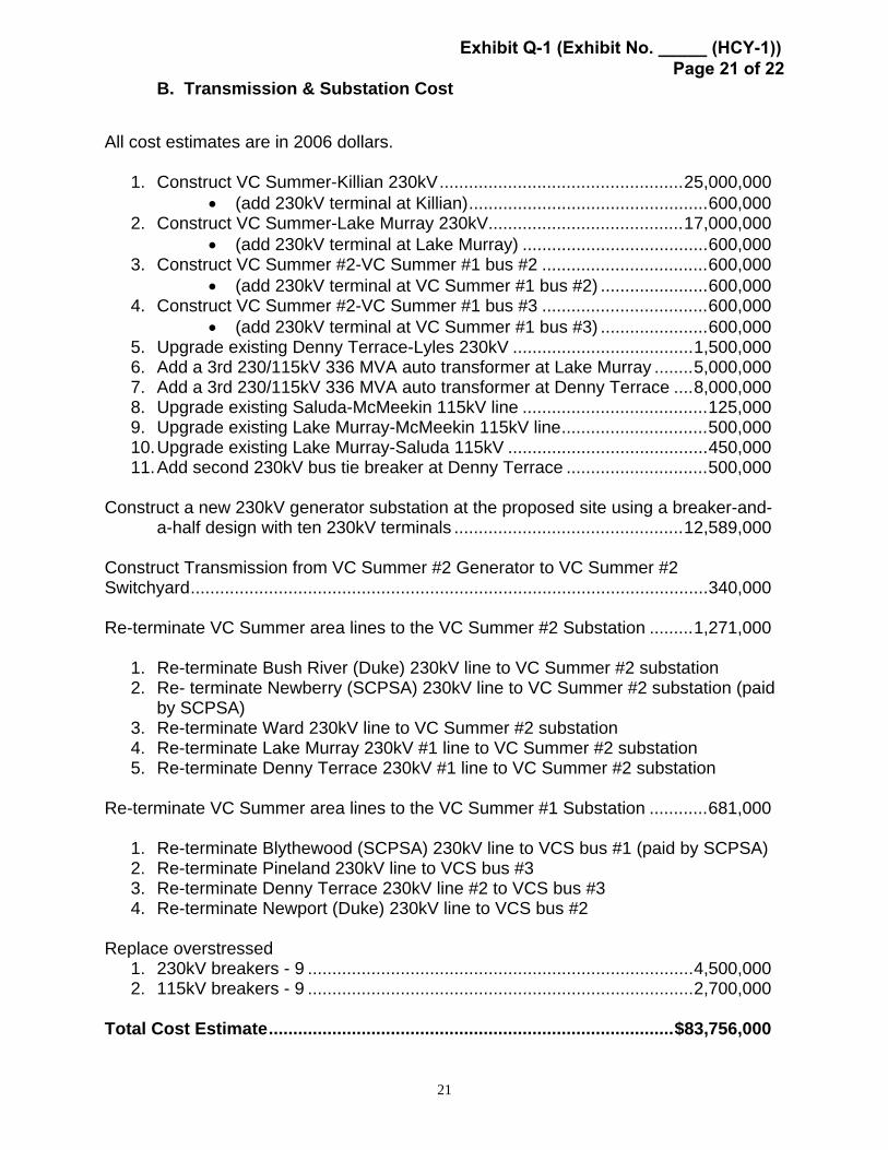
B. Transmission & Substation Cost All cost estimates are in 2006 dollars.
1. Construct VC Summer-Killian 230kV..................................................25,000,000 • (add 230kV terminal at Killian).................................................600,000
2. Construct VC Summer-Lake Murray 230kV........................................17,000,000 • (add 230kV terminal at Lake Murray) ......................................600,000
3. Construct VC Summer #2-VC Summer #1 bus #2 ..................................600,000 • (add 230kV terminal at VC Summer #1 bus #2) ......................600,000
4. Construct VC Summer #2-VC Summer #1 bus #3 ..................................600,000 • (add 230kV terminal at VC Summer #1 bus #3) ......................600,000
5. Upgrade existing Denny Terrace-Lyles 230kV .....................................1,500,000 6. Add a 3rd 230/115kV 336 MVA auto transformer at Lake Murray ........5,000,000 7. Add a 3rd 230/115kV 336 MVA auto transformer at Denny Terrace ....8,000,000 8. Upgrade existing Saluda-McMeekin 115kV line ......................................125,000 9. Upgrade existing Lake Murray-McMeekin 115kV line..............................500,000 10. Upgrade existing Lake Murray-Saluda 115kV .........................................450,000 11. Add second 230kV bus tie breaker at Denny Terrace .............................500,000
Construct a new 230kV generator substation at the proposed site using a breaker-and-
a-half design with ten 230kV terminals ...............................................12,589,000 Construct Transmission from VC Summer #2 Generator to VC Summer #2 Switchyard..........................................................................................................340,000 Re-terminate VC Summer area lines to the VC Summer #2 Substation .........1,271,000
1. Re-terminate Bush River (Duke) 230kV line to VC Summer #2 substation 2. Re- terminate Newberry (SCPSA) 230kV line to VC Summer #2 substation (paid
by SCPSA) 3. Re-terminate Ward 230kV line to VC Summer #2 substation 4. Re-terminate Lake Murray 230kV #1 line to VC Summer #2 substation 5. Re-terminate Denny Terrace 230kV #1 line to VC Summer #2 substation
Re-terminate VC Summer area lines to the VC Summer #1 Substation ............681,000
1. Re-terminate Blythewood (SCPSA) 230kV line to VCS bus #1 (paid by SCPSA) 2. Re-terminate Pineland 230kV line to VCS bus #3 3. Re-terminate Denny Terrace 230kV line #2 to VCS bus #3 4. Re-terminate Newport (Duke) 230kV line to VCS bus #2
Replace overstressed
1. 230kV breakers - 9 ...............................................................................4,500,000 2. 115kV breakers - 9 ...............................................................................2,700,000
Total Cost Estimate...................................................................................$83,756,000
Exhibit Q-1 (Exhibit No. _____ (HCY-1)) Page 21 of 22

22
V. Adjustments to the VC Summer #2 Interconnection Plan
SCE&G Transmission Planning is adjusting the VC Summer #2 generator interconnection plan to consider future native load needs of the system. The existing system has limited capability to serve future load growth along the Interstate 77 corridor. Without reactive compensation, the system can serve only an additional 40 MW of customer load. With reactive compensation, 81 MW can be served. Transmission Planning is expecting the load along I-77 to grow rapidly in the future, exceed the additional 81 MW amount and, at that time, the area will need additional transmission expansion to reliably serve the growing load. Transmission Planning is recommending that the VC Summer – Killian 230kV transmission line, discussed above in this report, be routed from VC Summer to Winnsboro and then to Killian. This will extend the 230kV line but with relatively little additional cost this will also provide for service along the I-77 corridor for many years into the future.
Exhibit Q-1 (Exhibit No. _____ (HCY-1)) Page 22 of 22


![Exhibit T - Countrywide RMBS Settlementcwrmbssettlement.com/docs/145 - CWALT 2007-OA8 PSA...Exhibit S 1: [Reserved] S 1 1 Exhibit S 2: [Reserved] S 2 1 Exhibit T: Officer’s Certificate](https://img.pdfslide.net/doc/110x75/5f05f63a7e708231d41598c3/exhibit-t-countrywide-rmbs-settle-cwalt-2007-oa8-psa-exhibit-s-1-reserved.jpg)