Embed Size (px)
Citation preview
Existing/Future Technology to Address Radiated Noise by Modifying Vessel
Propulsion and Operating Parameters(& a few other un-scheduled topics)
N. A. Brown
2007 NOAA Vessel-Quieting Symposium
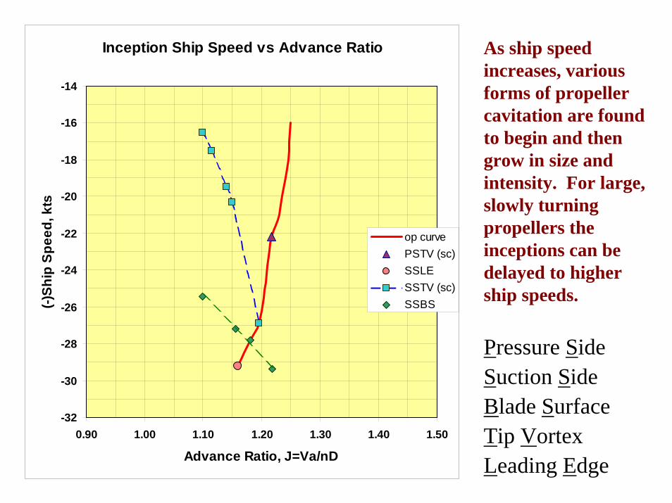
As ship speed increases, various forms of propeller cavitation are found to begin and then grow in size and intensity. For large, slowly turning propellers the inceptions can be delayed to higher ship speeds.
Pressure SideSuction SideBlade SurfaceTip VortexLeading Edge
Inception Ship Speed vs Advance Ratio
-32
-30
-28
-26
-24
-22
-20
-18
-16
-14
0.90 1.00 1.10 1.20 1.30 1.40 1.50
Advance Ratio, J=Va/nD
(-)Sh
ip S
peed
, kts
op curvePSTV (sc)SSLESSTV (sc)SSBS
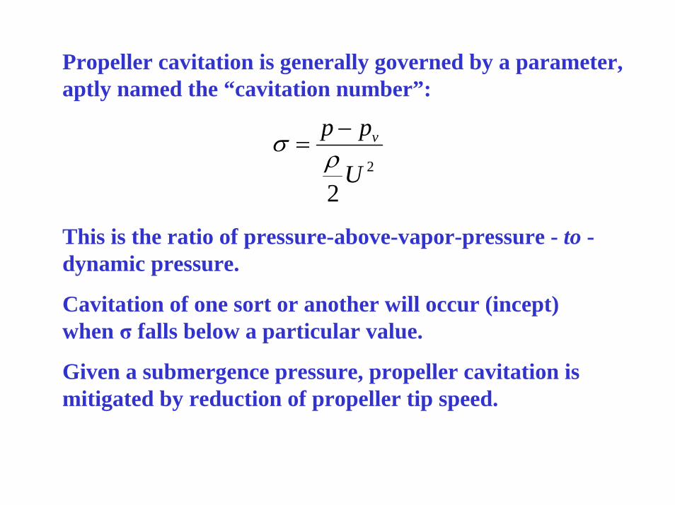
Propeller cavitation is generally governed by a parameter, aptly named the “cavitation number”:
2
2U
pp v
ρσ −=
This is the ratio of pressure-above-vapor-pressure - to -dynamic pressure.
Cavitation of one sort or another will occur (incept) when σ falls below a particular value.
Given a submergence pressure, propeller cavitation is mitigated by reduction of propeller tip speed.
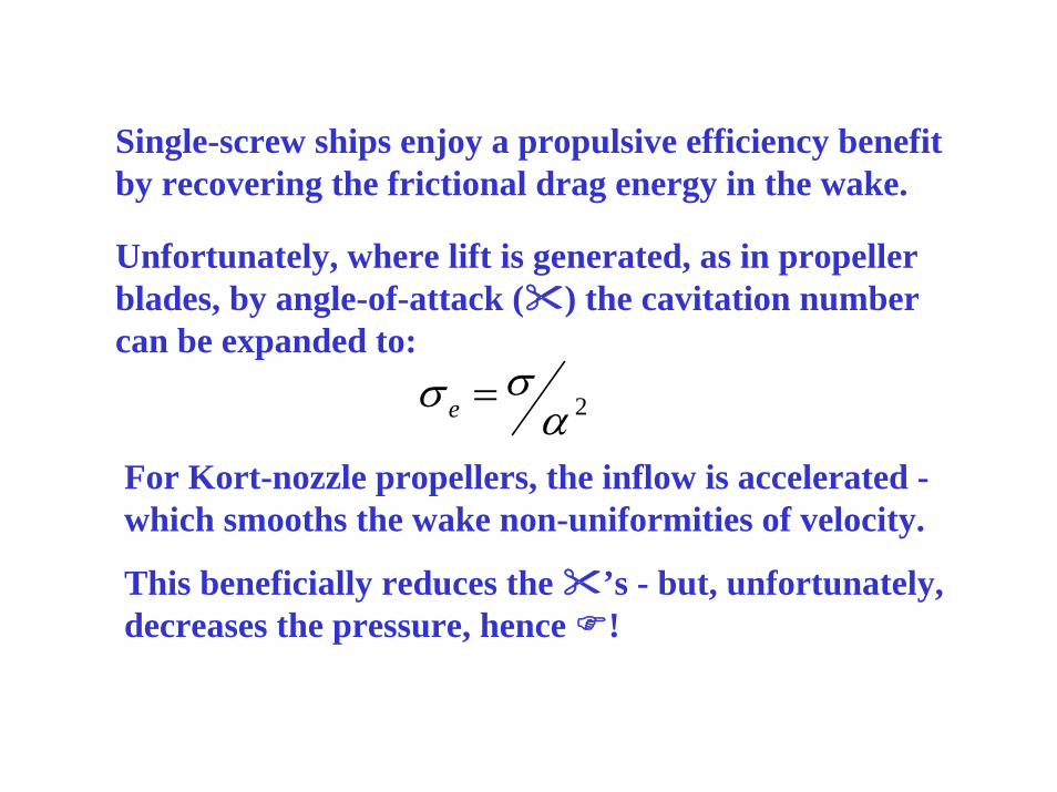
Unfortunately, where lift is generated, as in propeller blades, by angle-of-attack ( ) the cavitation number can be expanded to:
2ασσ =e
For Kort-nozzle propellers, the inflow is accelerated -which smooths the wake non-uniformities of velocity.
This beneficially reduces the ’s - but, unfortunately, decreases the pressure, hence !
Single-screw ships enjoy a propulsive efficiency benefit by recovering the frictional drag energy in the wake.
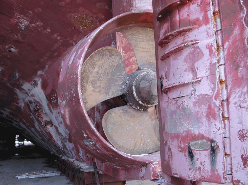
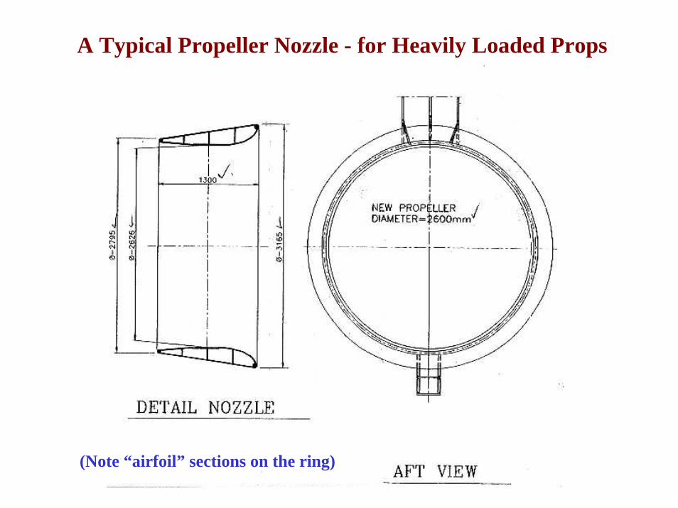
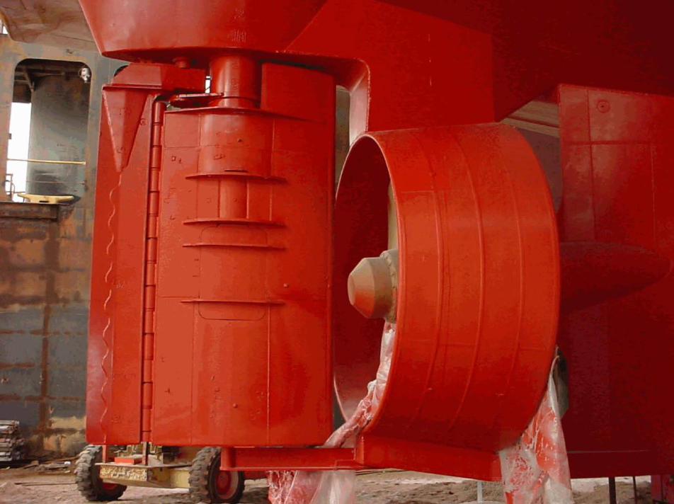
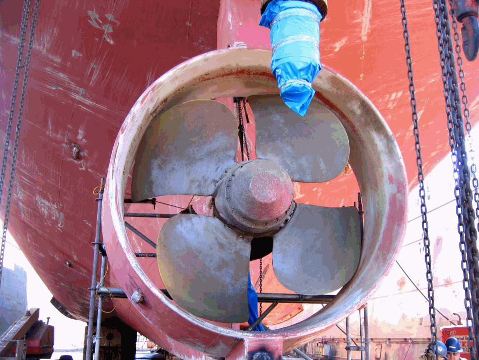
A Typical Propeller Nozzle - for Heavily Loaded Props
(Note “airfoil” sections on the ring)
An improved blade design for nozzle propellers is at hand - which promises to delay inception of cavitation and accommodate pitch changes on CRP’s
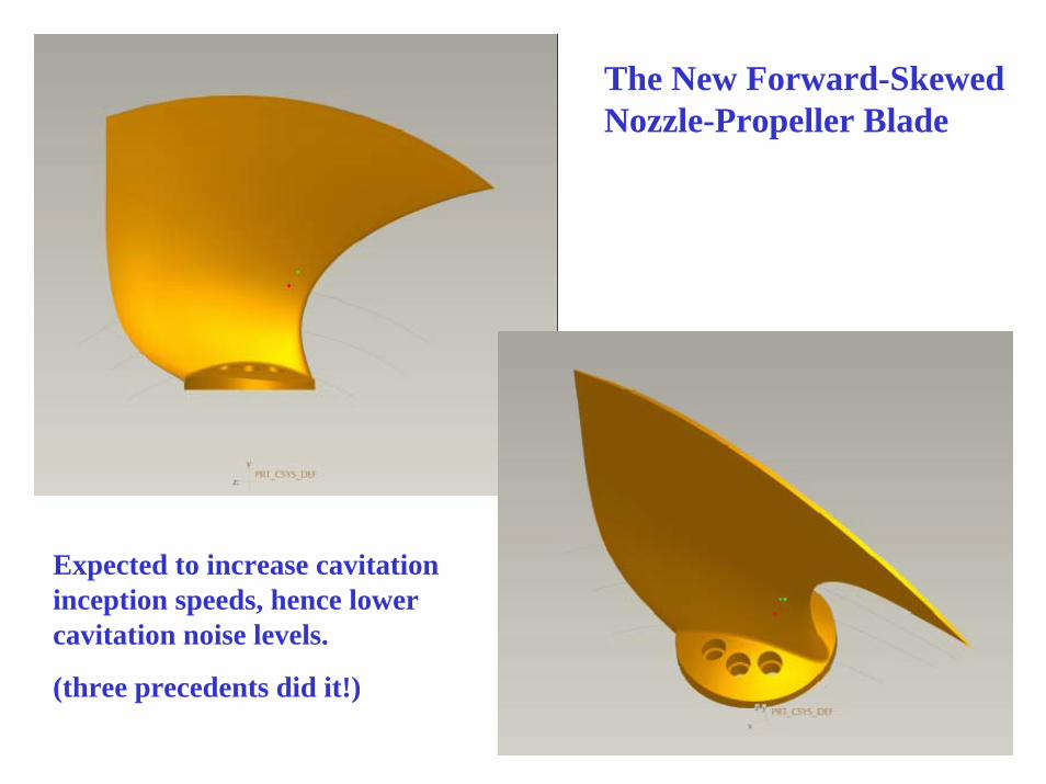
The New Forward-Skewed Nozzle-Propeller Blade
Expected to increase cavitation inception speeds, hence lower cavitation noise levels.
(three precedents did it!)
Observation of published data for families of propellers will show that optimum efficiency over a range of pitch-diameter ratios implies relative constancy of Kt, throughout.
For a given required thrust, T, then, there is some constancy of the product: nD2, or (nD)D. The first part is proportional to tip speed: Ut = nD. So the tip speed is found to be inversely proportional to diameter, roughly.
To maintain higher values of the cavitation number - in order to avoid or minimize cavitation - use large diameter propellers and turn them slowly.
Twin screws can do this much more readily than single screws.
Why Twin Screws?
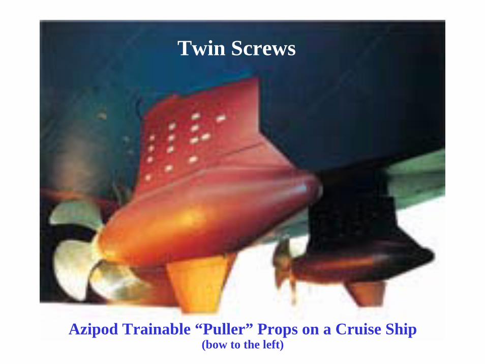
Azipod Trainable “Puller” Props on a Cruise Ship(bow to the left)
Twin Screws
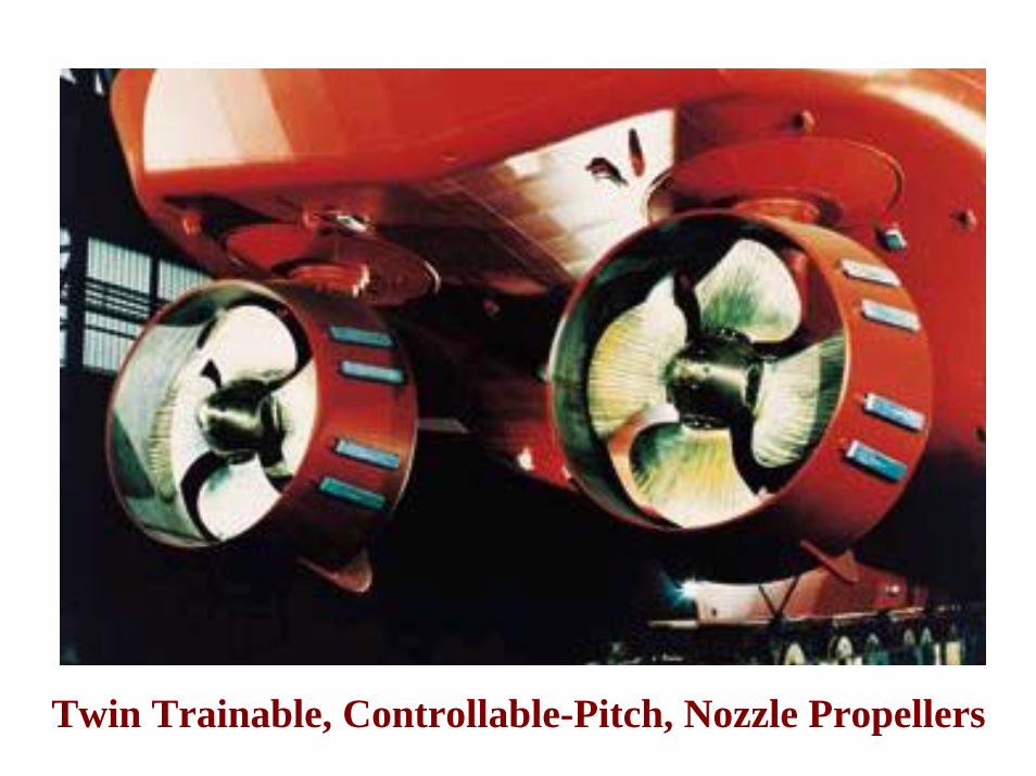
Twin Trainable, Controllable-Pitch, Nozzle Propellers
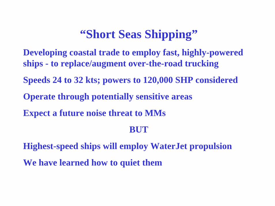
“Short Seas Shipping”Developing coastal trade to employ fast, highly-powered ships - to replace/augment over-the-road trucking
Speeds 24 to 32 kts; powers to 120,000 SHP considered
Operate through potentially sensitive areas
Expect a future noise threat to MMs
BUT
Highest-speed ships will employ WaterJet propulsion
We have learned how to quiet them
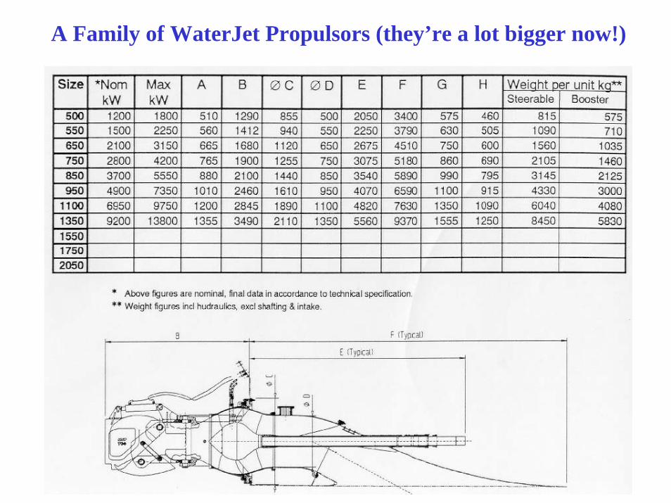
A Family of WaterJet Propulsors (they’re a lot bigger now!)
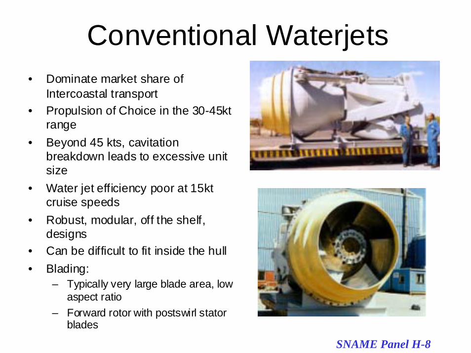
Conventional Waterjets• Dominate market share of
Intercoastal transport• Propulsion of Choice in the 30-45kt
range• Beyond 45 kts, cavitation
breakdown leads to excessive unitsize
• Water jet efficiency poor at 15ktcruise speeds
• Robust, modular, off the shelf,designs
• Can be difficult to fit inside the hull• Blading:
– Typically very large blade area, lowaspect ratio
– Forward rotor with postswirl statorblades
SNAME Panel H-8
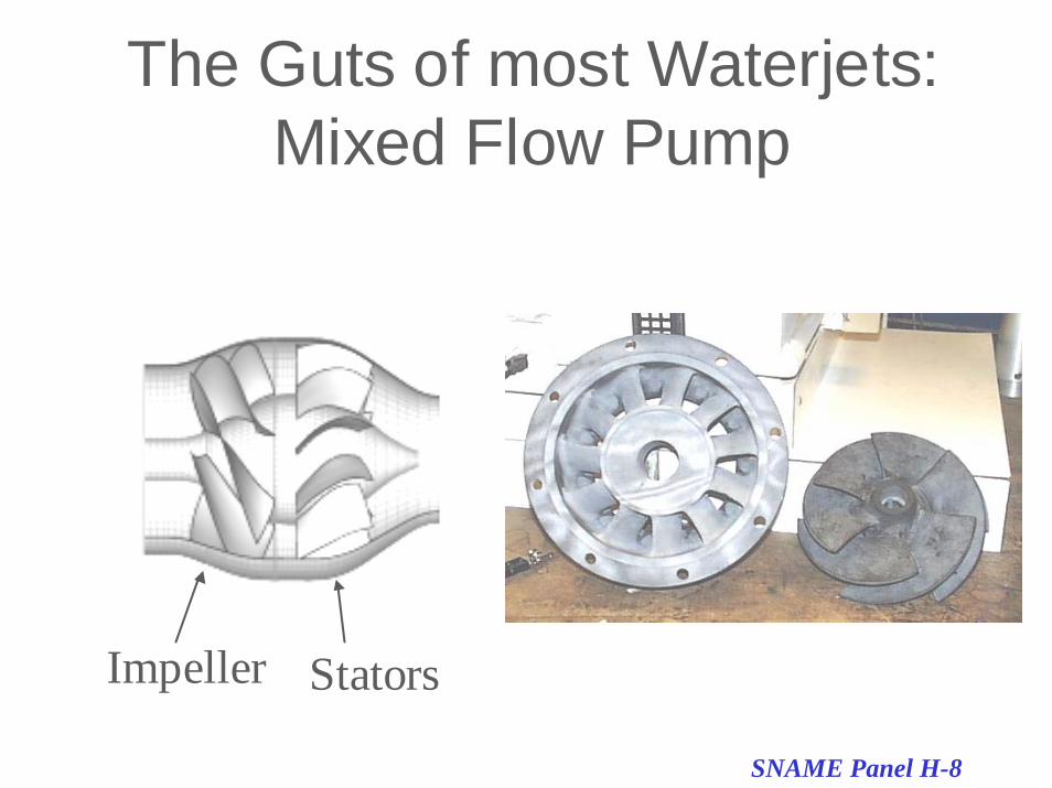
The Guts of most Waterjets:Mixed Flow Pump
Impeller Stators
SNAME Panel H-8
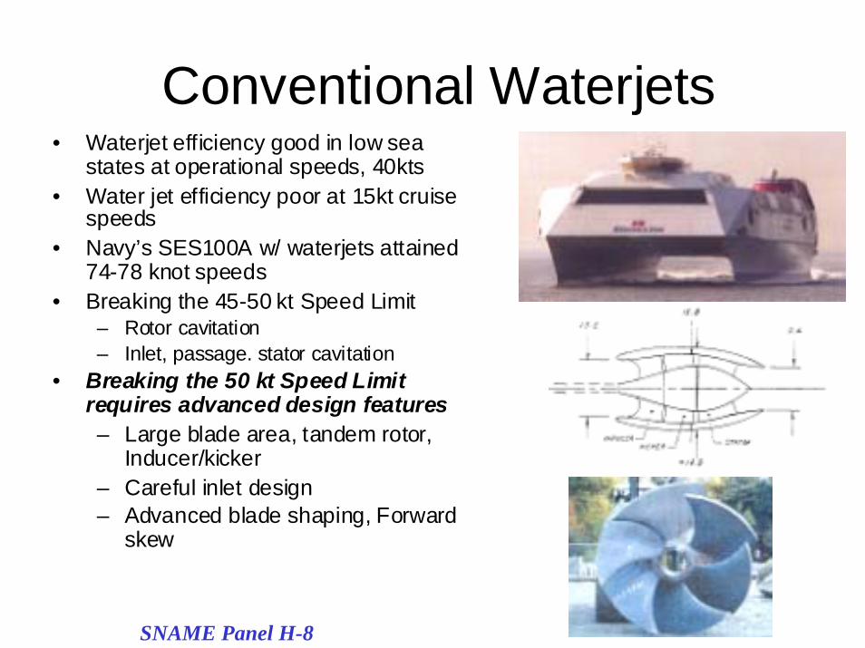
Conventional Waterjets• Waterjet efficiency good in low sea
states at operational speeds, 40kts• Water jet efficiency poor at 15kt cruise
speeds• Navy’s SES100A w/ waterjets attained
74-78 knot speeds• Breaking the 45-50 kt Speed Limit
– Rotor cavitation– Inlet, passage. stator cavitation
• Breaking the 50 kt Speed Limitrequires advanced design features– Large blade area, tandem rotor,
Inducer/kicker– Careful inlet design– Advanced blade shaping, Forward
skew
SNAME Panel H-8
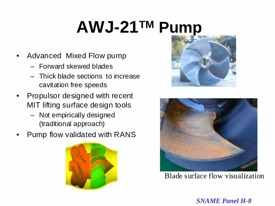
AWJ-21TM Pump• Advanced Mixed Flow pump
– Forward skewed blades– Thick blade sections to increase
cavitation free speeds• Propulsor designed with recent
MIT lifting surface design tools– Not empirically designed
(traditional approach)• Pump flow validated with RANS
Blade surface flow visualization
SNAME Panel H-8
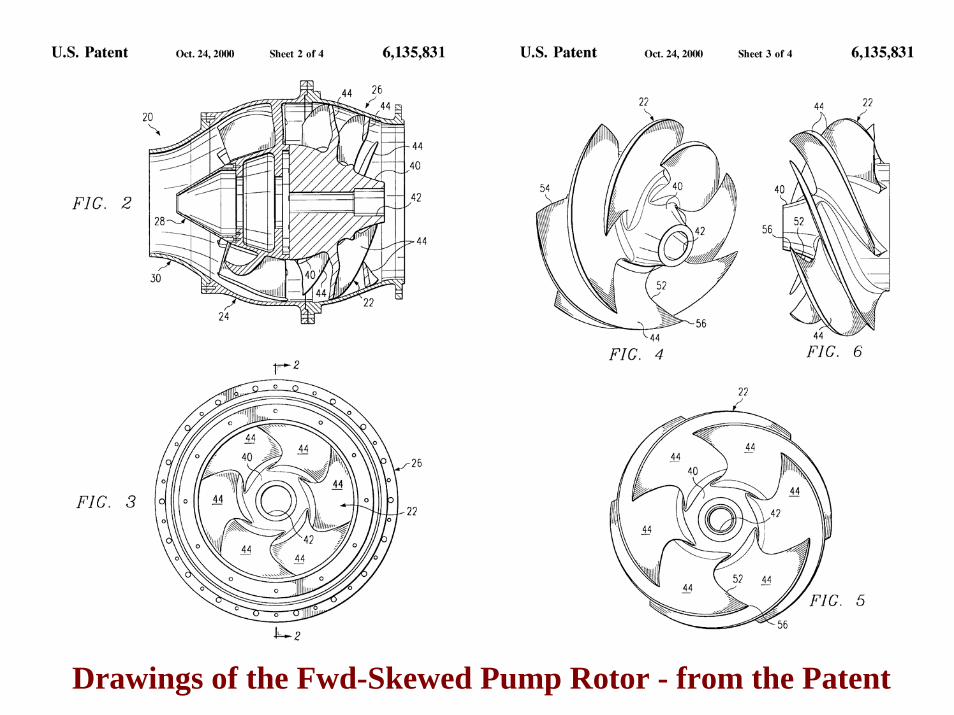
Drawings of the Fwd-Skewed Pump Rotor - from the Patent
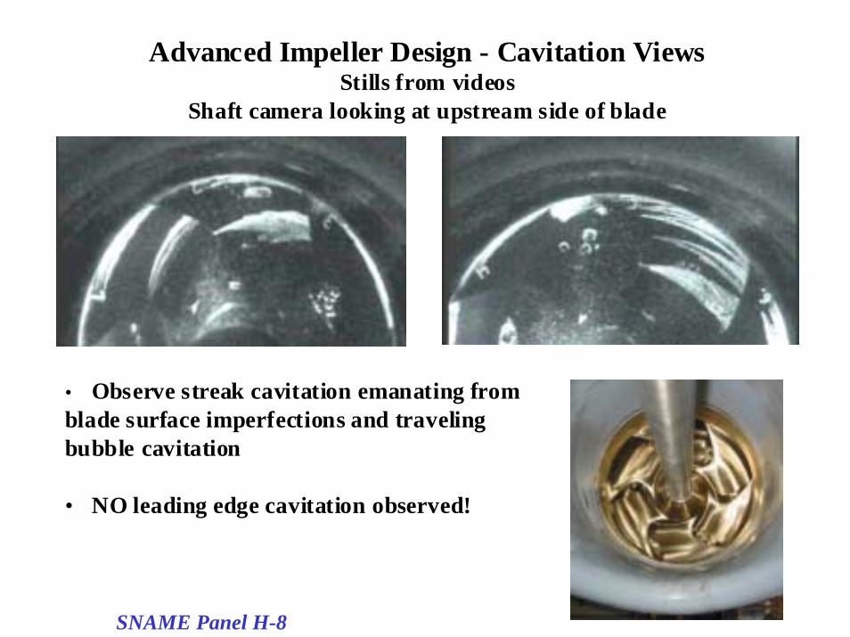
Advanced Impeller Design - Cavitation ViewsStills from videos
Shaft camera looking at upstream side of blade
• Observe streak cavitation emanating fromblade surface imperfections and travelingbubble cavitation
• NO leading edge cavitation observed!
SNAME Panel H-8
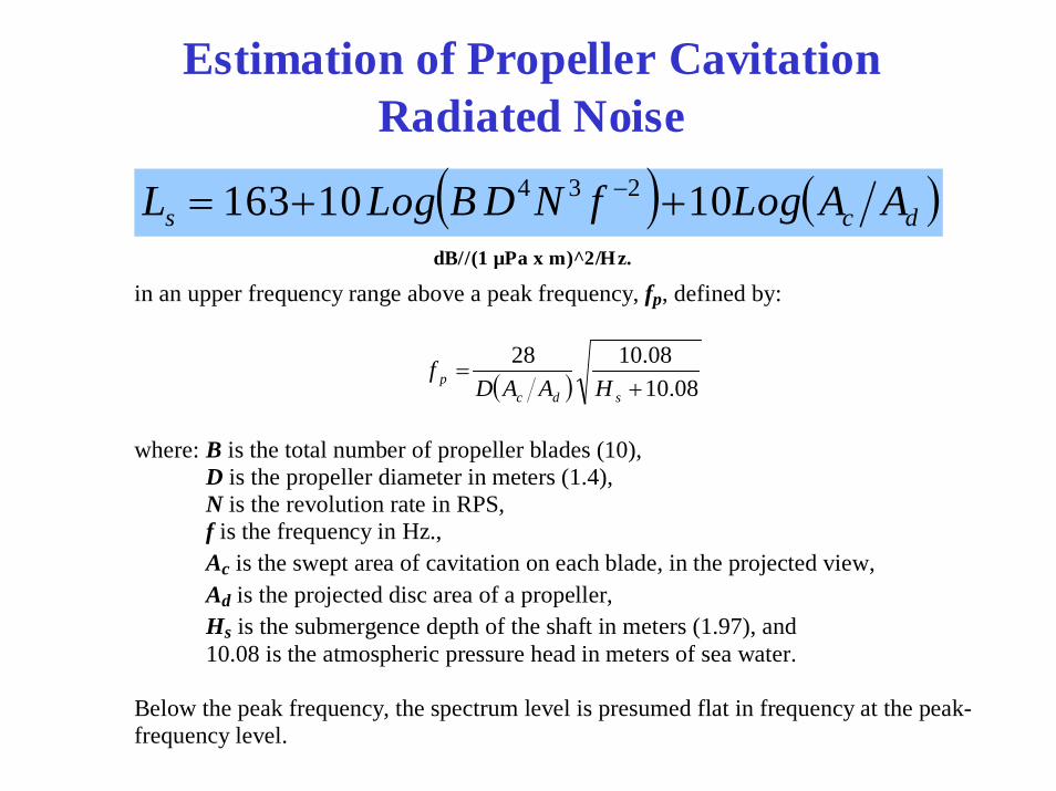
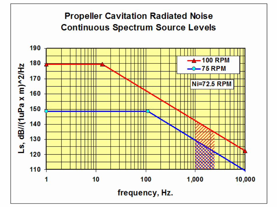
Estimation of Propeller CavitationRadiated Noise
( ) ( )dcs AALogfNDBLogL 1010163 234 ++= −
in an upper frequency range above a peak frequency, fp, defined by:
( ) 08.1008.1028
+=
sdcp HAAD
f
where: B is the total number of propeller blades (10), D is the propeller diameter in meters (1.4), N is the revolution rate in RPS, f is the frequency in Hz., Ac is the swept area of cavitation on each blade, in the projected view, Ad is the projected disc area of a propeller, Hs is the submergence depth of the shaft in meters (1.97), and 10.08 is the atmospheric pressure head in meters of sea water. Below the peak frequency, the spectrum level is presumed flat in frequency at the peak-frequency level.
dB//(1 µPa x m)^2/Hz.
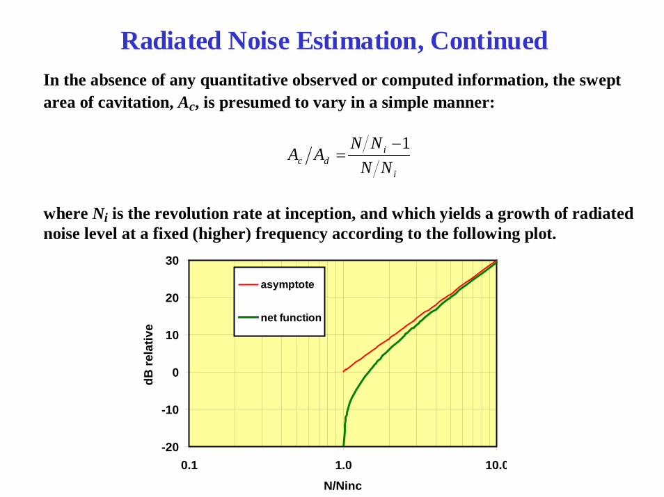
Radiated Noise Estimation, ContinuedIn the absence of any quantitative observed or computed information, the swept area of cavitation, Ac, is presumed to vary in a simple manner:
i
idc NN
NNAA
1−=
where Ni is the revolution rate at inception, and which yields a growth of radiated noise level at a fixed (higher) frequency according to the following plot.
-20
-10
0
10
20
30
0.1 1.0 10.0N/Ninc
dB re
lativ
e
asymptote
net function
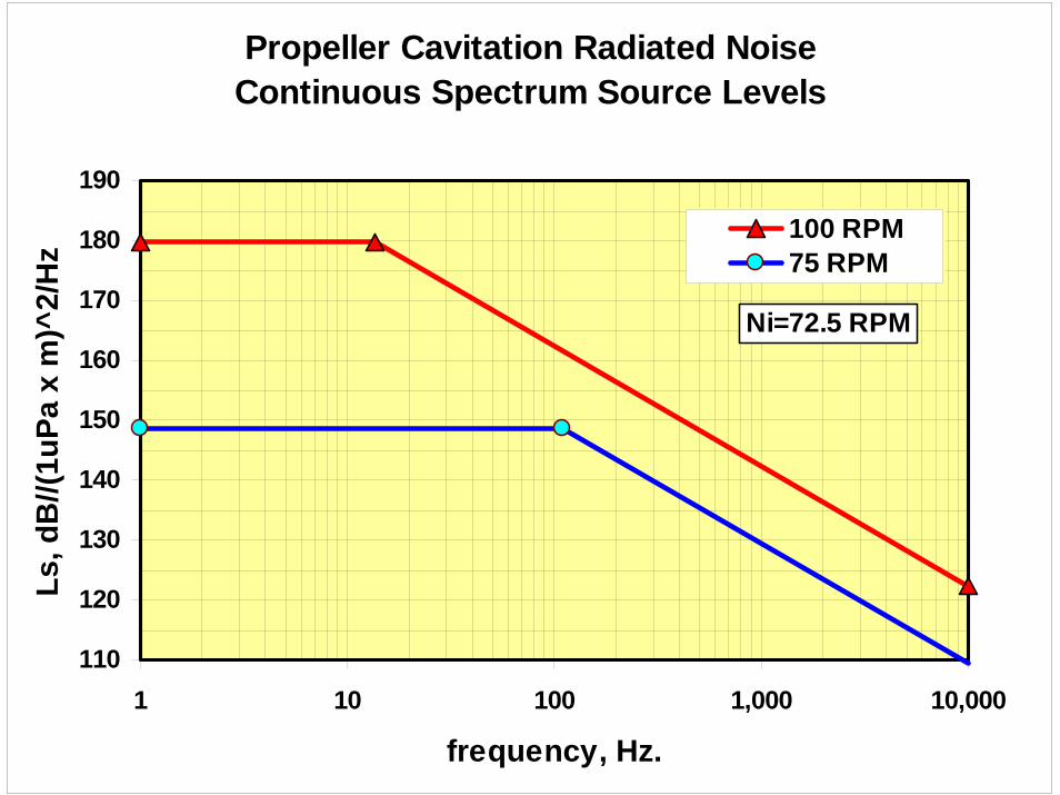
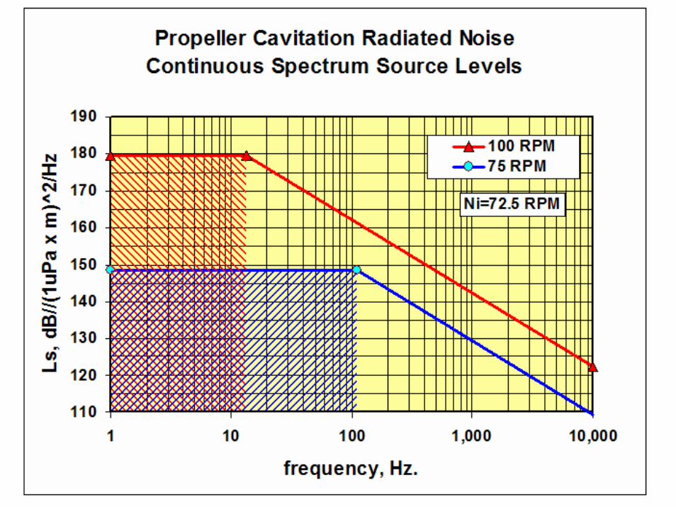
Propeller Cavitation Radiated Noise Continuous Spectrum Source Levels
110
120
130
140
150
160
170
180
190
1 10 100 1,000 10,000
frequency, Hz.
Ls, d
B//(
1uPa
x m
)^2/
Hz
100 RPM75 RPM
Ni=72.5 RPM
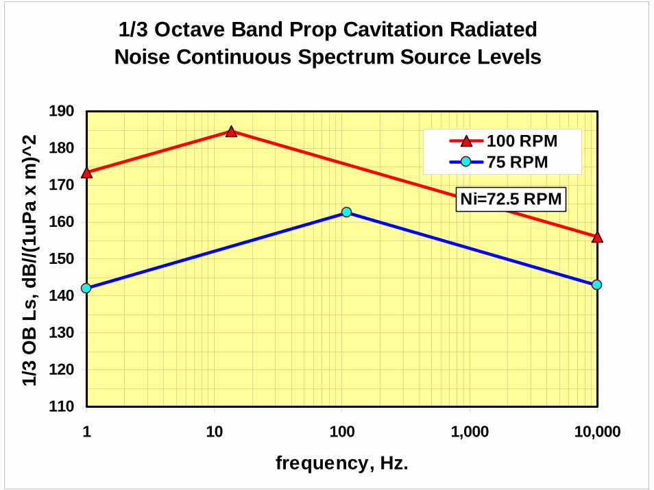
1/3 Octave Band Prop Cavitation Radiated Noise Continuous Spectrum Source Levels
110
120
130
140
150
160
170
180
190
1 10 100 1,000 10,000
frequency, Hz.
1/3
OB
Ls,
dB
//(1u
Pa x
m)^
2 100 RPM75 RPM
Ni=72.5 RPM
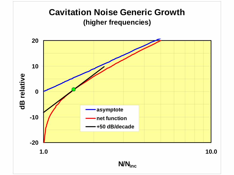
Cavitation Noise Generic Growth(higher frequencies)
-20
-10
0
10
20
1.0 10.0
N/Ninc
dB re
lativ
e
asymptotenet function+50 dB/decade
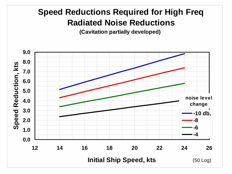
Speed Reductions Required for High Freq Radiated Noise Reductions
(Cavitation partially developed)
0.0
1.0
2.0
3.0
4.0
5.0
6.0
7.0
8.0
9.0
12 14 16 18 20 22 24 26
Initial Ship Speed, kts
Spee
d R
educ
tion,
kts
-10 db,-8-6-4
noise levelchange
(50 Log)
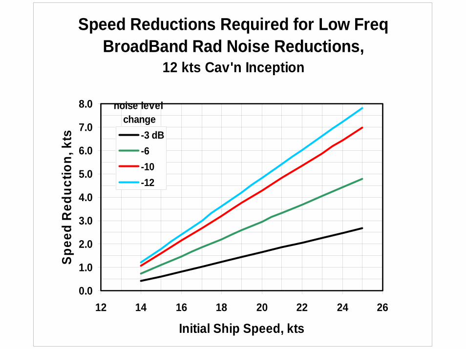
Speed Reductions Required for Low Freq BroadBand Rad Noise Reductions,
12 kts Cav'n Inception
0.0
1.0
2.0
3.0
4.0
5.0
6.0
7.0
8.0
12 14 16 18 20 22 24 26
Initial Ship Speed, kts
Spee
d R
educ
tion,
kts -3 dB
-6-10-12
noise level change
The cost of noise reduction by temporary vessel slowing is easily estimated.
The increased voyage time represents lost revenue.
The shipping company must be compensated for that loss.
Non-compliance must be similarly penalized.
Cost
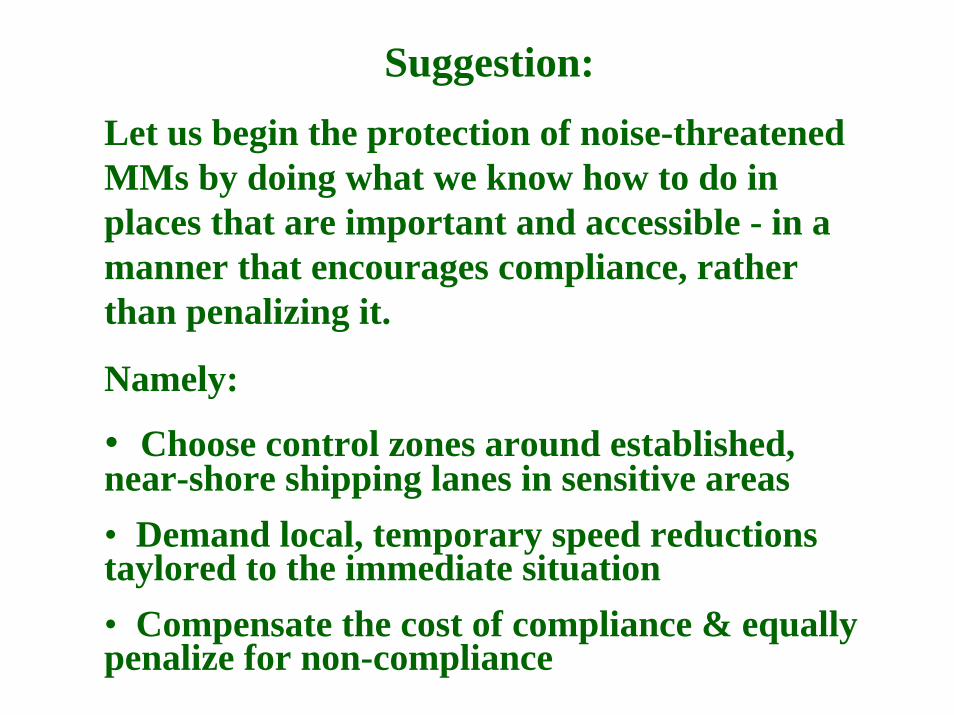
Suggestion:Let us begin the protection of noise-threatened MMs by doing what we know how to do in places that are important and accessible - in a manner that encourages compliance, rather than penalizing it.
Namely:
• Choose control zones around established, near-shore shipping lanes in sensitive areas• Demand local, temporary speed reductions taylored to the immediate situation• Compensate the cost of compliance & equally penalize for non-compliance
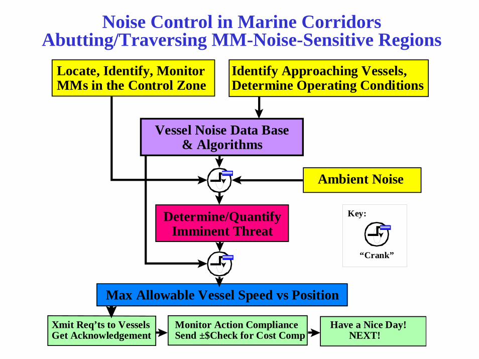
Noise Control in Marine CorridorsAbutting/Traversing MM-Noise-Sensitive Regions
Locate, Identify, MonitorMMs in the Control Zone
Identify Approaching Vessels,Determine Operating Conditions
Vessel Noise Data Base& Algorithms
Ambient Noise
Determine/QuantifyImminent Threat
Max Allowable Vessel Speed vs Position
Xmit Req’ts to Vessels Monitor Action Compliance Have a Nice Day!Get Acknowledgement Send ±$Check for Cost Comp NEXT!
Key:
“Crank”
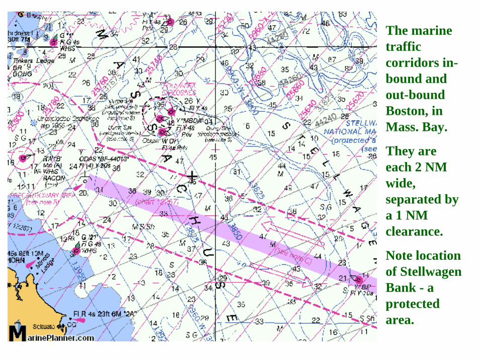
The marine traffic corridors in-bound and out-bound Boston, in Mass. Bay.
They are each 2 NM wide, separated by a 1 NM clearance.
Note location of Stellwagen Bank - a protected area.
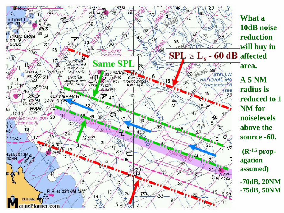
What a 10dB noise reduction will buy in affected area.
A 5 NM radius is reduced to 1 NM for noiselevelsabove the source -60.
(R-1.5 prop-agationassumed)
-70dB, 20NM -75dB, 50NM
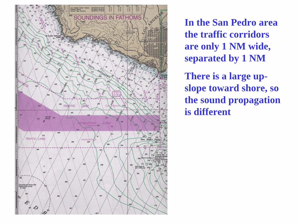
In the San Pedro area the traffic corridors are only 1 NM wide, separated by 1 NM
There is a large up-slope toward shore, so the sound propagation is different
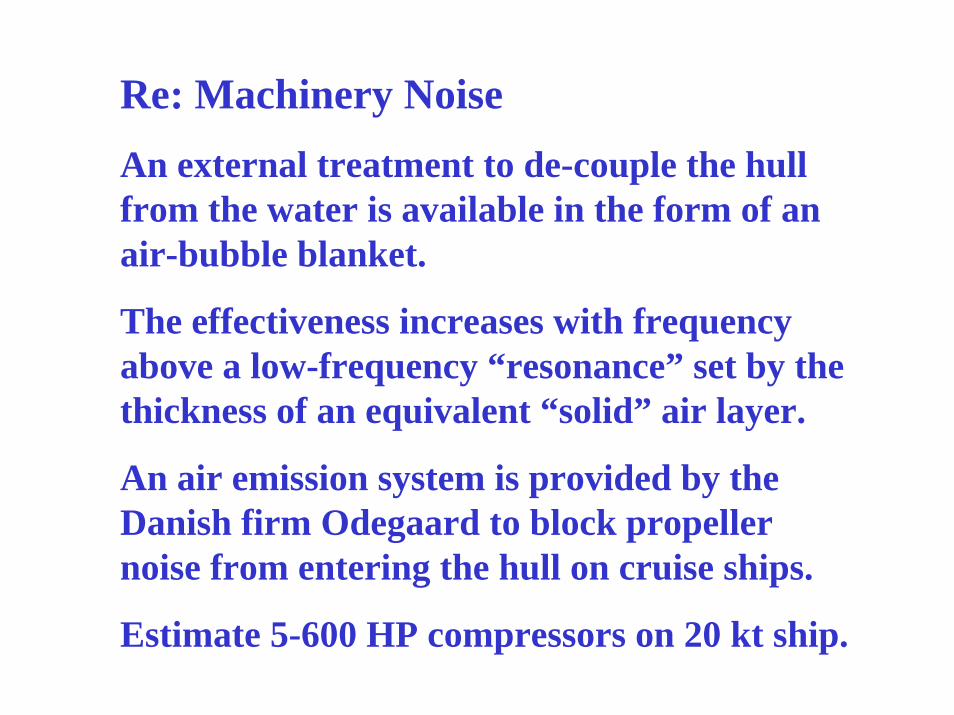
Re: Machinery NoiseAn external treatment to de-couple the hull from the water is available in the form of an air-bubble blanket.
The effectiveness increases with frequency above a low-frequency “resonance” set by the thickness of an equivalent “solid” air layer.
An air emission system is provided by the Danish firm Odegaard to block propeller noise from entering the hull on cruise ships.
Estimate 5-600 HP compressors on 20 kt ship.