Embed Size (px)
Citation preview
Page | 1
EX.NO:1 STUDY OF SOFTWARE ENGINEERING METHODOLOGIES
DATE :
SOFTWARE:
Software is any set of machine-readable instructions that directs a computer's
processor to perform specific operations
SOFTWARE ENGINEERING:
Software engineering is the study and application of engineering to the design,
development, and maintenance of software.
The following are different phases in software development.
1. Requirement gathering and analysis
2. Design
3. Implementation or coding
4. Testing
5. Deployment
6. Maintenance
1) Requirement gathering and analysis: Business requirements are gathered in this
phase. This phase is the main focus of the project managers and stake holders. Meetings with
managers, stake holders and users are held in order to determine the requirements like; who
is going to use the system? How will they use the system? What data should be input into
the system? What data should be output by the system? These are general questions that get
answered during a requirements gathering phase. After requirement gathering these
requirements are analyzed for their validity and the possibility of incorporating the
requirements in the system to be development is also studied. Finally, a Requirement
Specification document is created which serves the purpose of guideline for the next phase of
the model.
2) Design: In this phase the system and software design is prepared from the requirement
specifications which were studied in the first phase. System Design helps in specifying
hardware and system requirements and also helps in defining overall system architecture.
The system design specifications serve as input for the next phase of the model.
3) Implementation / Coding: On receiving system design documents, the work is divided
in modules/units and actual coding is started. Since, in this phase the code is produced so it is
the main focus for the developer. This is the longest phase of the software development life
cycle.
4) Testing: After the code is developed it is tested against the requirements to make sure
that the product is actually solving the needs addressed and gathered during the requirements
Page | 2
phase. During this phase unit testing, integration testing, system testing, acceptance testing
are done.
5) Deployment: After successful testing the product is delivered / deployed to the customer
for their use.
6) Maintenance: Once when the customers starts using the developed system then the actual
problems comes up and needs to be solved from time to time. This process where the care is
taken for the developed product is known as maintenance.
Lifecycle model types
1. Prescriptive process model
1. Water fall model
2. Incremental process Model
3. Evolutionary process Model
1. Prototyping model
2. Spiral Model
4. The concurrent development Model
2. Specialized Process Model
1. Component based development Model
2. Formal Methods Model
3. Aspect oriented S/W development (AOSD)
3. Unified process model
1. Problem Analysis and Project Planning -Thorough study of the problem – Identify
Project scope, Objectives and Infrastructure.
Problem Analysis
Problem analysis is the process of understanding real-world problems and user needs
and proposing solutions to meet those needs.
A problem can be defined as the difference between things as perceived and things as
desired.
o “what is” vs. “what should be”
o “what is given” vs. “what is needed”
The goal of problem analysis is to gain a better understanding of the problem being
solved before development begins.
Project Planning
Project Planning is the application of knowledge, skills, tools, and techniques to
project activities to meet project requirements. It is accomplished through the application and
integration of the project management processes of initiating, planning, executing,
monitoring and controlling, and closing
Page | 3
2. Software Requirement Analysis - Describe the individual Phases/modules of the project
and Identify deliverables.
Requirements analysis, also called requirements engineering, is the process of
determining user expectations for a new or modified product. These features, called
requirements, must be quantifiable, relevant and detailed. In software engineering, such
requirements are often called functional specifications. Requirements analysis is an important
aspect of project management.
Requirements analysis involves frequent communication with system users to
determine specific feature expectations, resolution of conflict or ambiguity in requirements as
demanded by the various users or groups of users, avoidance of feature creep and
documentation of all aspects of the project development process from start to finish. Energy
should be directed towards ensuring that the final system or product conforms to client needs
rather than attempting to mold user expectations to fit the requirements.
Requirements analysis is a team effort that demands a combination of hardware,
software and human factors engineering expertise as well as skills in dealing with people.
3. Data Modeling - Use work products – data dictionary, use case diagrams and activity
diagrams, build and test class diagrams, sequence diagrams and add interface to class
diagrams. Data modeling in software engineering is the process of creating a data model for
an information system by applying formal data modeling techniques.
Data dictionary:
A data dictionary, or metadata repository, as defined in the IBM Dictionary of
Computing, is a "centralized repository of information about data such as meaning,
relationships to other data, origin, usage, and format."
UML DIAGRAMS:
There are three classifications of UML diagrams:
Behavior diagrams. A type of diagram that depicts behavioral features of a
system or business process. This includes activity, state machine, and use case
diagrams as well as the four interaction diagrams.
Interaction diagrams. A subset of behavior diagrams which emphasize object
interactions. This includes communication, interaction overview, sequence, and
timing diagrams.
Structure diagrams. A type of diagram that depicts the elements of a specification
that are irrespective of time. This includes class, composite structure, component,
deployment, object, and package diagrams.

Page | 4
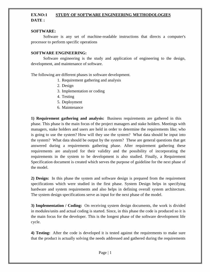
USE CASE DIAGRAM:
A use case diagram is a type of behavioral diagram defined by the Unified
Modeling Language (UML). Its purpose is to present a graphical overview of the
functionality provided by a system in terms of actors, their goals- represented as use cases-
and any dependencies between those use cases.
Use case diagram depict:
Use cases. A use case describes a sequence of actions that provide something of
measurable value to an actor and is drawn as a horizontal ellipse.
Actors. An actor is a person, organization, or external system that plays a role in one
or more interactions with your system. Actors are drawn as stick figures.
Associations. Associations between actors and use cases are indicated in use case
diagrams by solid lines. An association exists whenever an actor is involved with an
interaction described by a use case. Associations are modeled as lines connecting use
cases and actors to one another, with an optional arrowhead on one end of the line.
The arrowhead is often used to indicating the direction of the initial invocation of the
relationship or to indicate the primary actor within the use case. The arrowheads are
typically confused with data flow and as a result I avoid their use.
System boundary boxes (optional). You can draw a rectangle around the use cases,
called the system boundary box, to indicate the scope of your system. Anything
within the box represents functionality that is in scope and anything outside the box is
not. System boundary boxes are rarely used, although on occasion I have used them
to identify which use cases will be delivered in each major release of a system.
Packages (optional). Packages are UML constructs that enable you to organize
model elements (such as use cases) into groups. Packages are depicted as file folders
and can be used on any of the UML diagrams, including both use case diagrams and
class diagrams. I use packages only when my diagrams become unwieldy, which
generally implies they cannot be printed on a single page, to organize a large diagram
into smaller ones.
Page | 5
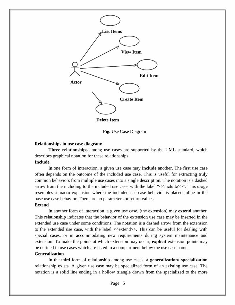
Fig. Use Case Diagram
Relationships in use case diagram:
Three relationships among use cases are supported by the UML standard, which
describes graphical notation for these relationships.
Include
In one form of interaction, a given use case may include another. The first use case
often depends on the outcome of the included use case. This is useful for extracting truly
common behaviors from multiple use cases into a single description. The notation is a dashed
arrow from the including to the included use case, with the label “<<include>>”. This usage
resembles a macro expansion where the included use case behavior is placed inline in the
base use case behavior. There are no parameters or return values.
Extend
In another form of interaction, a given use case, (the extension) may extend another.
This relationship indicates that the behavior of the extension use case may be inserted in the
extended use case under some conditions. The notation is a dashed arrow from the extension
to the extended use case, with the label <<extend>>. This can be useful for dealing with
special cases, or in accommodating new requirements during system maintenance and
extension. To make the points at which extension may occur, explicit extension points may
be defined in use cases which are listed in a compartment below the use case name.
Generalization
In the third form of relationship among use cases, a generalization/ specialization
relationship exists. A given use case may be specialized form of an existing use case. The
notation is a solid line ending in a hollow triangle drawn from the specialized to the more
List Items
View Item
Edit Item
Create Item
Delete Item
Actor
Page | 6
general use case. This resembles the object-oriented concept of sub-classing, in practice it
can be both useful and effective to factor common behaviors, constraints and assumptions to
the general use case, describe them once, and deal same as except details in the specialized
cases.
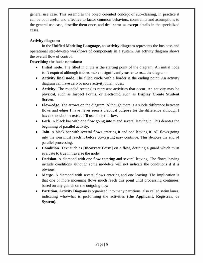
Activity diagram:
In the Unified Modeling Language, an activity diagram represents the business and
operational step-by-step workflows of components in a system. An activity diagram shows
the overall flow of control.
Describing the basic notations:
Initial node. The filled in circle is the starting point of the diagram. An initial node
isn’t required although it does make it significantly easier to read the diagram.
Activity final node. The filled circle with a border is the ending point. An activity
diagram can have zero or more activity final nodes.
Activity. The rounded rectangles represent activities that occur. An activity may be
physical, such as Inspect Forms, or electronic, such as Display Create Student
Screen.
Flow/edge. The arrows on the diagram. Although there is a subtle difference between
flows and edges I have never seen a practical purpose for the difference although I
have no doubt one exists. I’ll use the term flow.
Fork. A black bar with one flow going into it and several leaving it. This denotes the
beginning of parallel activity.
Join. A black bar with several flows entering it and one leaving it. All flows going
into the join must reach it before processing may continue. This denotes the end of
parallel processing.
Condition. Text such as [Incorrect Form] on a flow, defining a guard which must
evaluate to true in traverse the node.
Decision. A diamond with one flow entering and several leaving. The flows leaving
include conditions although some modelers will not indicate the conditions if it is
obvious.
Merge. A diamond with several flows entering and one leaving. The implication is
that one or more incoming flows much reach this point until processing continues,
based on any guards on the outgoing flow.
Partition. Activity Diagram is organized into many partitions, also called swim lanes,
indicating who/what is performing the activities (the Applicant, Registrar, or
System).
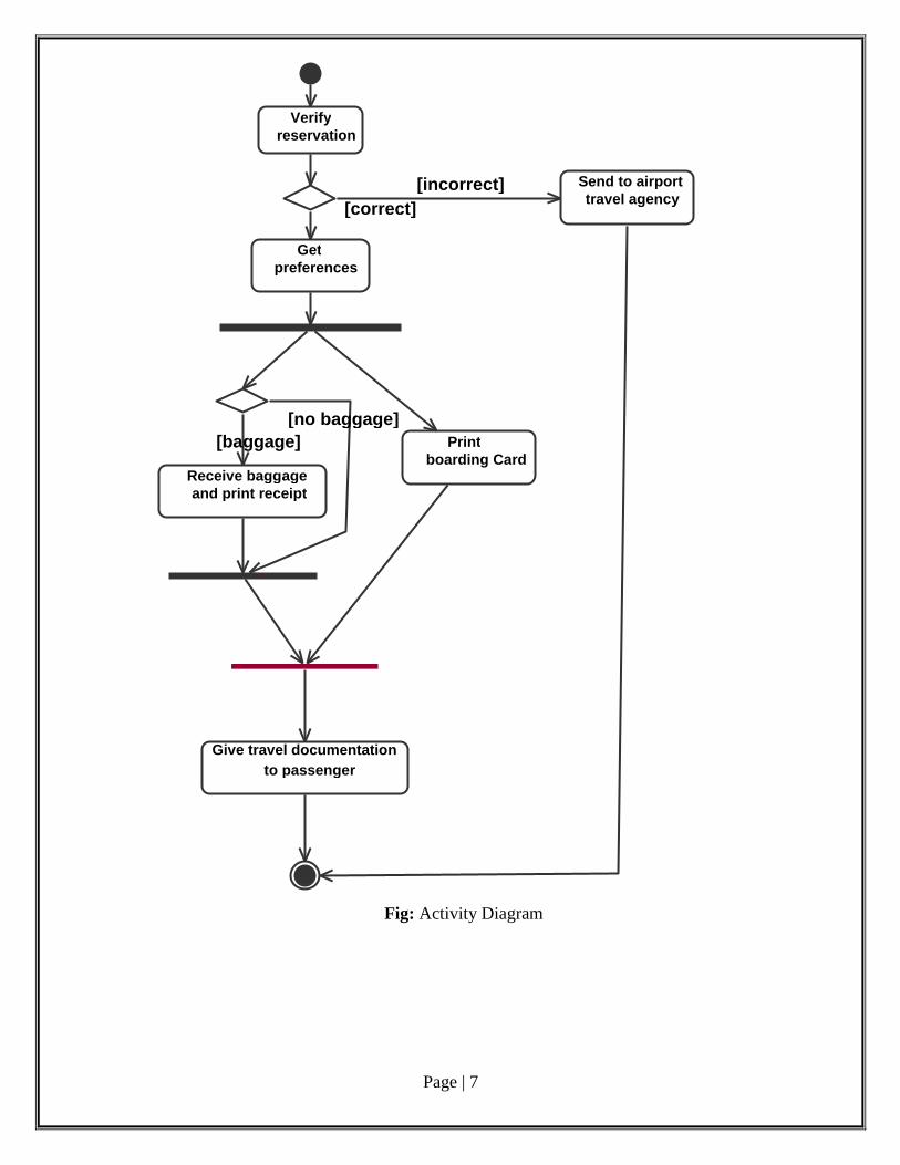
Page | 7
Fig: Activity Diagram
Verify
reservation
Get
preferences
Send to airport
travel agency
Receive baggage
and print receipt
boarding Card
Give travel documentation
to passenger
[baggage]
[no baggage]
[correct]
[incorrect]
Page | 8
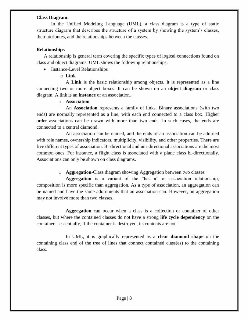
Class Diagram:
In the Unified Modeling Language (UML), a class diagram is a type of static
structure diagram that describes the structure of a system by showing the system’s classes,
their attributes, and the relationships between the classes.
Relationships
A relationship is general term covering the specific types of logical connections found on
class and object diagrams. UML shows the following relationships:
Instance-Level Relationships
o Link
A Link is the basic relationship among objects. It is represented as a line
connecting two or more object boxes. It can be shown on an object diagram or class
diagram. A link is an instance or an association.
o Association
An Association represents a family of links. Binary associations (with two
ends) are normally represented as a line, with each end connected to a class box. Higher
order associations can be drawn with more than two ends. In such cases, the ends are
connected to a central diamond.
An association can be named, and the ends of an association can be adorned
with role names, ownership indicators, multiplicity, visibility, and other properties. There are
five different types of association. Bi-directional and uni-directional associations are the most
common ones. For instance, a flight class is associated with a plane class bi-directionally.
Associations can only be shown on class diagrams.
o Aggregation-Class diagram showing Aggregation between two classes
Aggregation is a variant of the “has a” or association relationship;
composition is more specific than aggregation. As a type of association, an aggregation can
be named and have the same adornments that an association can. However, an aggregation
may not involve more than two classes.
Aggregation can occur when a class is a collection or container of other
classes, but where the contained classes do not have a strong life cycle dependency on the
container—essentially, if the container is destroyed, its contents are not.
In UML, it is graphically represented as a clear diamond shape on the
containing class end of the tree of lines that connect contained class(es) to the containing
class.
Page | 9
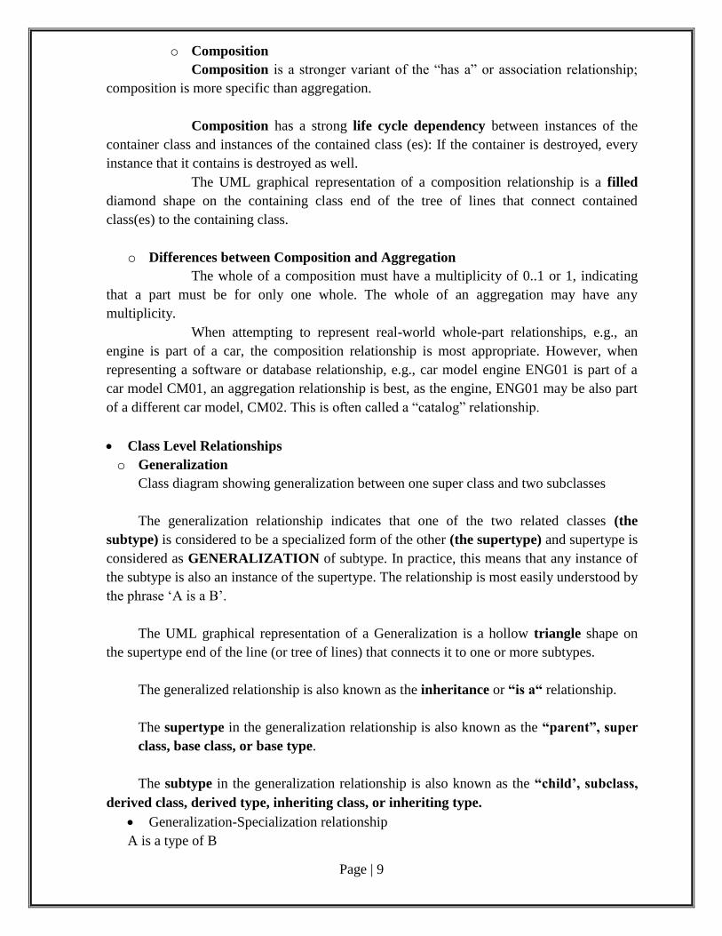
o Composition
Composition is a stronger variant of the “has a” or association relationship;
composition is more specific than aggregation.
Composition has a strong life cycle dependency between instances of the
container class and instances of the contained class (es): If the container is destroyed, every
instance that it contains is destroyed as well.
The UML graphical representation of a composition relationship is a filled
diamond shape on the containing class end of the tree of lines that connect contained
class(es) to the containing class.
o Differences between Composition and Aggregation
The whole of a composition must have a multiplicity of 0..1 or 1, indicating
that a part must be for only one whole. The whole of an aggregation may have any
multiplicity.
When attempting to represent real-world whole-part relationships, e.g., an
engine is part of a car, the composition relationship is most appropriate. However, when
representing a software or database relationship, e.g., car model engine ENG01 is part of a
car model CM01, an aggregation relationship is best, as the engine, ENG01 may be also part
of a different car model, CM02. This is often called a “catalog” relationship.
Class Level Relationships
o Generalization
Class diagram showing generalization between one super class and two subclasses
The generalization relationship indicates that one of the two related classes (the
subtype) is considered to be a specialized form of the other (the supertype) and supertype is
considered as GENERALIZATION of subtype. In practice, this means that any instance of
the subtype is also an instance of the supertype. The relationship is most easily understood by
the phrase ‘A is a B’.
The UML graphical representation of a Generalization is a hollow triangle shape on
the supertype end of the line (or tree of lines) that connects it to one or more subtypes.
The generalized relationship is also known as the inheritance or “is a“ relationship.
The supertype in the generalization relationship is also known as the “parent”, super
class, base class, or base type.
The subtype in the generalization relationship is also known as the “child’, subclass,
derived class, derived type, inheriting class, or inheriting type.
Generalization-Specialization relationship
A is a type of B
Page | 10
E.g.”an oak is a type of tree”, “a sedan is a type of vehicle”
o Realization
In UML modeling, a realization relationship is relationship between model elements,
in which one model element (the client) realizes the behavior that the other model element
(the supplier) specifies. A realization is displayed in the diagram editor as a dashed line with
an unfilled arrowhead towards the supplier.
General Relationship
o Dependency(UML)
A dependency exists between two defined elements if a change to the definition of one
would result in a change to the other. This is indicated by a dashed pointing from the
dependent to the independent element. Several named varieties exist. A dependency can be
between instances, class, or both.
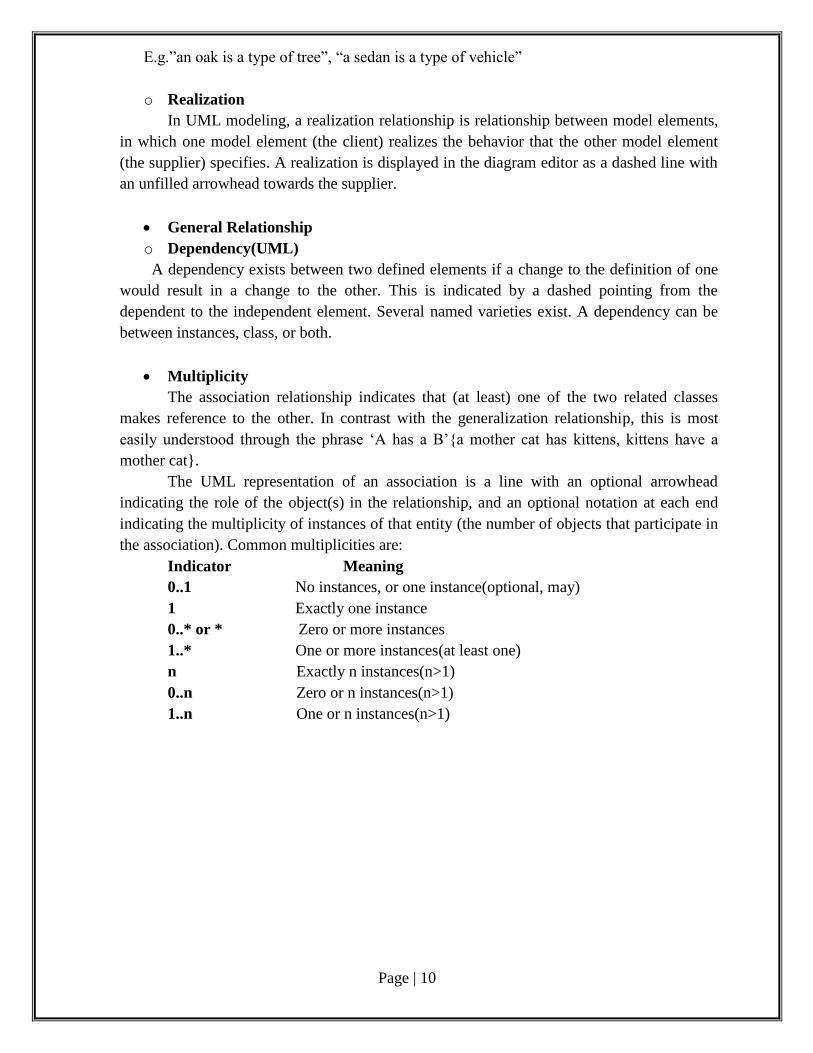
Multiplicity
The association relationship indicates that (at least) one of the two related classes
makes reference to the other. In contrast with the generalization relationship, this is most
easily understood through the phrase ‘A has a B’{a mother cat has kittens, kittens have a
mother cat}.
The UML representation of an association is a line with an optional arrowhead
indicating the role of the object(s) in the relationship, and an optional notation at each end
indicating the multiplicity of instances of that entity (the number of objects that participate in
the association). Common multiplicities are:
Indicator Meaning
0..1 No instances, or one instance(optional, may)
1 Exactly one instance
0..* or * Zero or more instances
1..* One or more instances(at least one)
n Exactly n instances(n>1)
0..n Zero or n instances(n>1)
1..n One or n instances(n>1)
Page | 11
Fig. Multiplicity and dependency
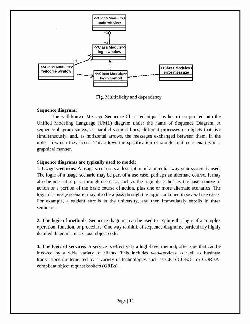
Sequence diagram:
The well-known Message Sequence Chart technique has been incorporated into the
Unified Modeling Language (UML) diagram under the name of Sequence Diagram. A
sequence diagram shows, as parallel vertical lines, different processes or objects that live
simultaneously, and, as horizontal arrows, the messages exchanged between them, in the
order in which they occur. This allows the specification of simple runtime scenarios in a
graphical manner.
Sequence diagrams are typically used to model:
1. Usage scenarios. A usage scenario is a description of a potential way your system is used.
The logic of a usage scenario may be part of a use case, perhaps an alternate course. It may
also be one entire pass through use case, such as the logic described by the basic course of
action or a portion of the basic course of action, plus one or more alternate scenarios. The
logic of a usage scenario may also be a pass through the logic contained in several use cases.
For example, a student enrolls in the university, and then immediately enrolls in three
seminars.
2. The logic of methods. Sequence diagrams can be used to explore the logic of a complex
operation, function, or procedure. One way to think of sequence diagrams, particularly highly
detailed diagrams, is a visual object code.
3. The logic of services. A service is effectively a high-level method, often one that can be
invoked by a wide variety of clients. This includes web-services as well as business
transactions implemented by a variety of technologies such as CICS/COBOL or CORBA-
compliant object request brokers (ORBs).
login control <<Class Module>> error message
<<Class Module>>
main window <<Class Module>>
welcome window <<Class Module>>
login window <<Class Module>>
+1
+1
+1 +1
Page | 12
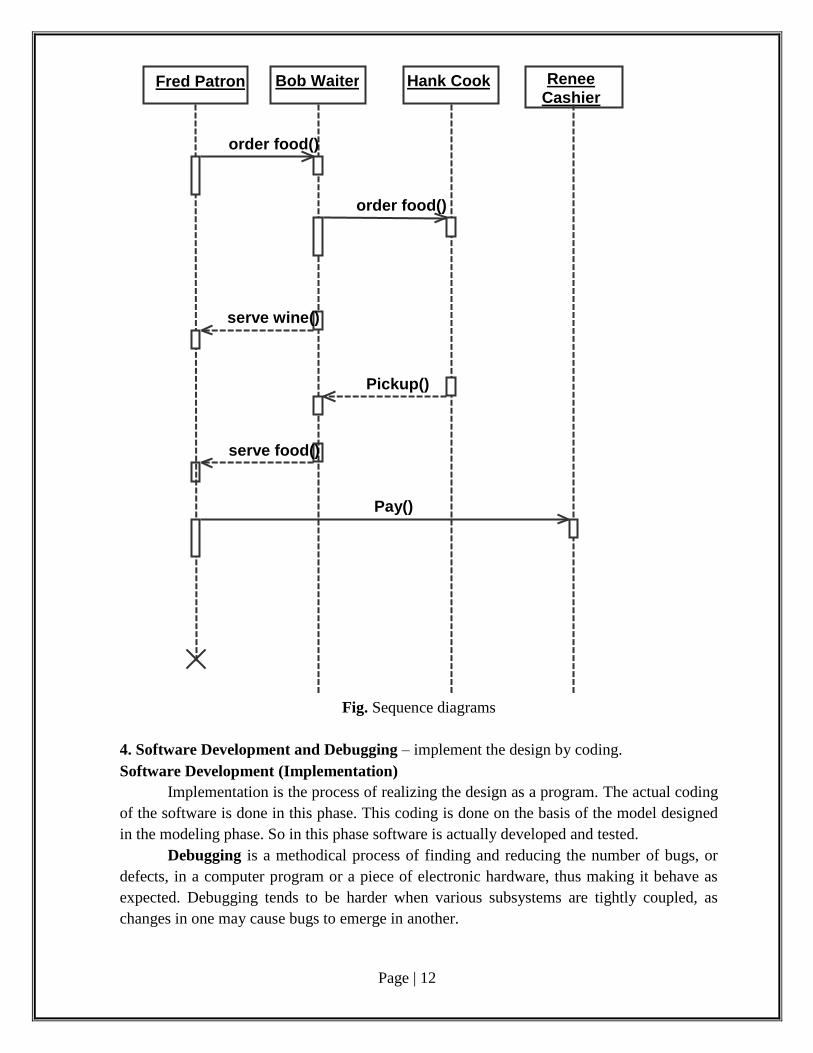
Fig. Sequence diagrams
4. Software Development and Debugging – implement the design by coding.
Software Development (Implementation)
Implementation is the process of realizing the design as a program. The actual coding
of the software is done in this phase. This coding is done on the basis of the model designed
in the modeling phase. So in this phase software is actually developed and tested.
Debugging is a methodical process of finding and reducing the number of bugs, or
defects, in a computer program or a piece of electronic hardware, thus making it behave as
expected. Debugging tends to be harder when various subsystems are tightly coupled, as
changes in one may cause bugs to emerge in another.
Fred Patron Bob Waiter Hank Cook Renee
Cashier
order food()
order food()
serve wine()
Pickup()
serve food()
Pay()
Page | 13
5. Software Testing - Prepare test plan, perform validation testing, coverage analysis,
memory leaks, develop test case hierarchy, Site check and site monitor.
Software testing is an investigation conducted to provide stakeholders with information
about the quality of the product or service under test. Software testing can also provide an
objective, independent view of the software to allow the business to appreciate and
understand the risks of software implementation. Test techniques include, but are not limited
to, the process of executing a program or application with the intent of finding software
bugs (errors or other defects).
It involves the execution of a software component or system to evaluate one or more
properties of interest. In general, these properties indicate the extent to which the component
or system under test:
meets the requirements that guided its design and development,
responds correctly to all kinds of inputs,
performs its functions within an acceptable time,
is sufficiently usable,
can be installed and run in its intended environments, and
Achieves the general result its stakeholders desire.
Test case
A test case is a set of conditions or variables under which a tester will determine
whether a system under test satisfies requirements or works correctly.
The process of developing test cases can also help find problems in the requirements
or design of an application.
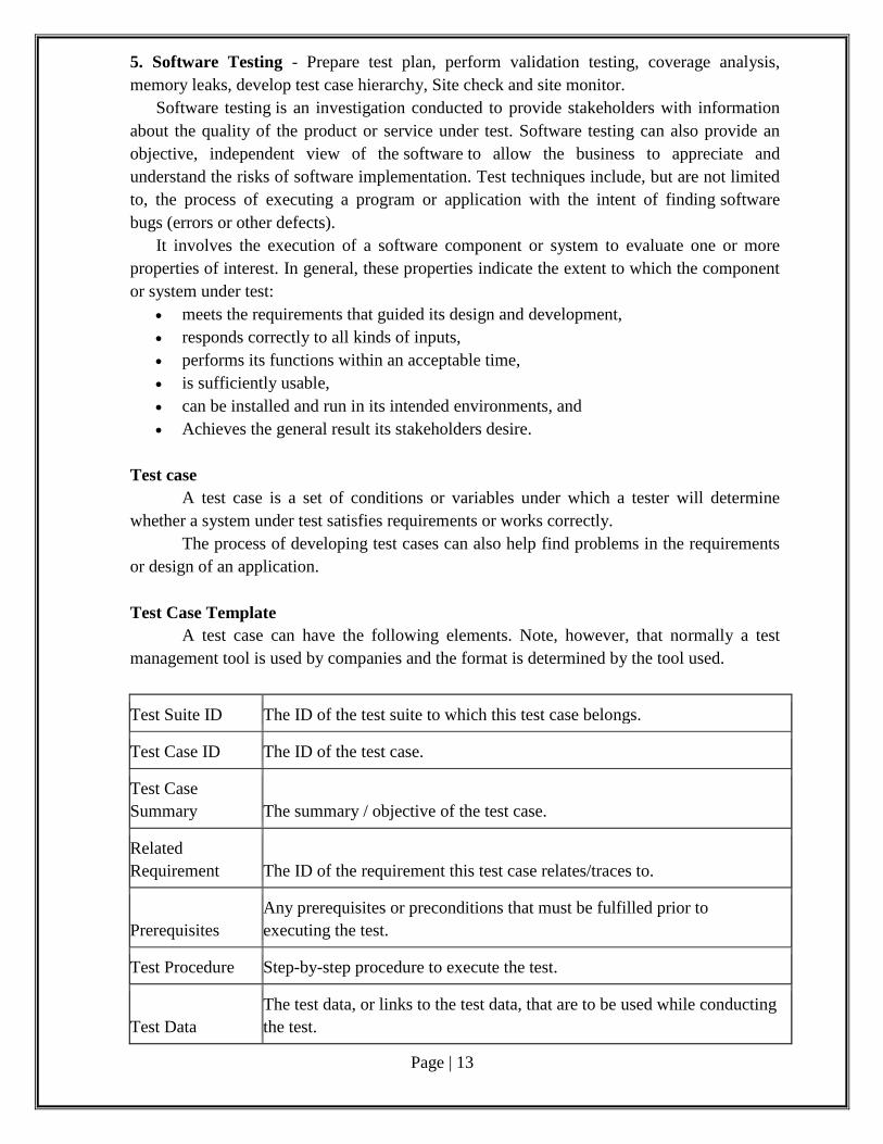
Test Case Template
A test case can have the following elements. Note, however, that normally a test
management tool is used by companies and the format is determined by the tool used.
Test Suite ID The ID of the test suite to which this test case belongs.
Test Case ID The ID of the test case.
Test Case
Summary The summary / objective of the test case.
Related
Requirement The ID of the requirement this test case relates/traces to.
Prerequisites
Any prerequisites or preconditions that must be fulfilled prior to
executing the test.
Test Procedure Step-by-step procedure to execute the test.
Test Data
The test data, or links to the test data, that are to be used while conducting
the test.
Page | 14
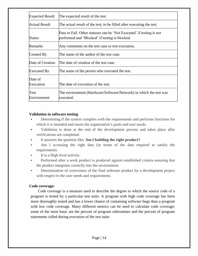
Expected Result The expected result of the test.
Actual Result The actual result of the test; to be filled after executing the test.
Status
Pass or Fail. Other statuses can be ‘Not Executed’ if testing is not
performed and ‘Blocked’ if testing is blocked.
Remarks Any comments on the test case or test execution.
Created By The name of the author of the test case.
Date of Creation The date of creation of the test case.
Executed By The name of the person who executed the test.
Date of
Execution The date of execution of the test.
Test
Environment
The environment (Hardware/Software/Network) in which the test was
executed.
Validation in software testing
Determining if the system complies with the requirements and performs functions for
which it is intended and meets the organization’s goals and user needs.
Validation is done at the end of the development process and takes place after
verifications are completed.
It answers the question like: Am I building the right product?
Am I accessing the right data (in terms of the data required to satisfy the
requirement).
It is a High level activity.
Performed after a work product is produced against established criteria ensuring that
the product integrates correctly into the environment.
Determination of correctness of the final software product by a development project
with respect to the user needs and requirements.
Code coverage:
Code coverage is a measure used to describe the degree to which the source code of a
program is tested by a particular test suite. A program with high code coverage has been
more thoroughly tested and has a lower chance of containing software bugs than a program
with low code coverage. Many different metrics can be used to calculate code coverage;
some of the most basic are the percent of program subroutines and the percent of program
statements called during execution of the test suite.
Page | 15
Code coverage analysis is the process of:
Finding areas of a program not exercised by a set of test cases, Creating additional
test cases to increase coverage, and Determining a quantitative measure of code coverage,
which is an indirect measure of quality.
Memory leak
Memory leak refers to software programs which consume memory but fail to release
it. This will usually cause memory overflow, slowing down the entire system and sometimes
crashing the software. Memory leaks are a common issue when writing programs in Java
language. Java garbage collector will destroy the ghost objects which do not have any
references in the memory, however if you leave a reference open to objects, the garbage
collector will fail to remove that object and the memory will be kept in use.
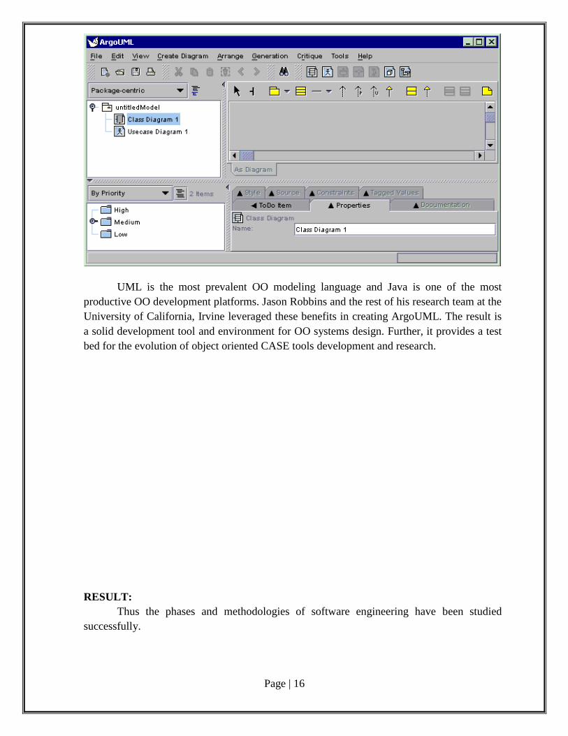
ArgoUML
ArgoUML was conceived as a tool and environment for use in the analysis and design
of object-oriented software systems. In this sense it is similar to many of the commercial
CASE tools that are sold as tools for modeling software systems. ArgoUML has a number of
very important distinctions from many of these tools.
1. It is free.
2. ArgoUML draws on research in cognitive psychology to provide novel features that
increase productivity by supporting the cognitive needs of object-oriented software designers
and architects.
3. ArgoUML supports open standards extensively - UML, XMI, SVG, OCL and others.
4. ArgoUML is a 100% pure Java application. This allows ArgoUML to run on all platforms
for which a reliable port of the Java platform is available.
5. ArgoUML is an open source project. The availability of the source ensures that a new
generation of software designers and researchers now have a proven framework from which
they can drive the development and evolution of CASE tool technologies.
Page | 16
UML is the most prevalent OO modeling language and Java is one of the most
productive OO development platforms. Jason Robbins and the rest of his research team at the
University of California, Irvine leveraged these benefits in creating ArgoUML. The result is
a solid development tool and environment for OO systems design. Further, it provides a test
bed for the evolution of object oriented CASE tools development and research.
RESULT:
Thus the phases and methodologies of software engineering have been studied
successfully.
Page | 17
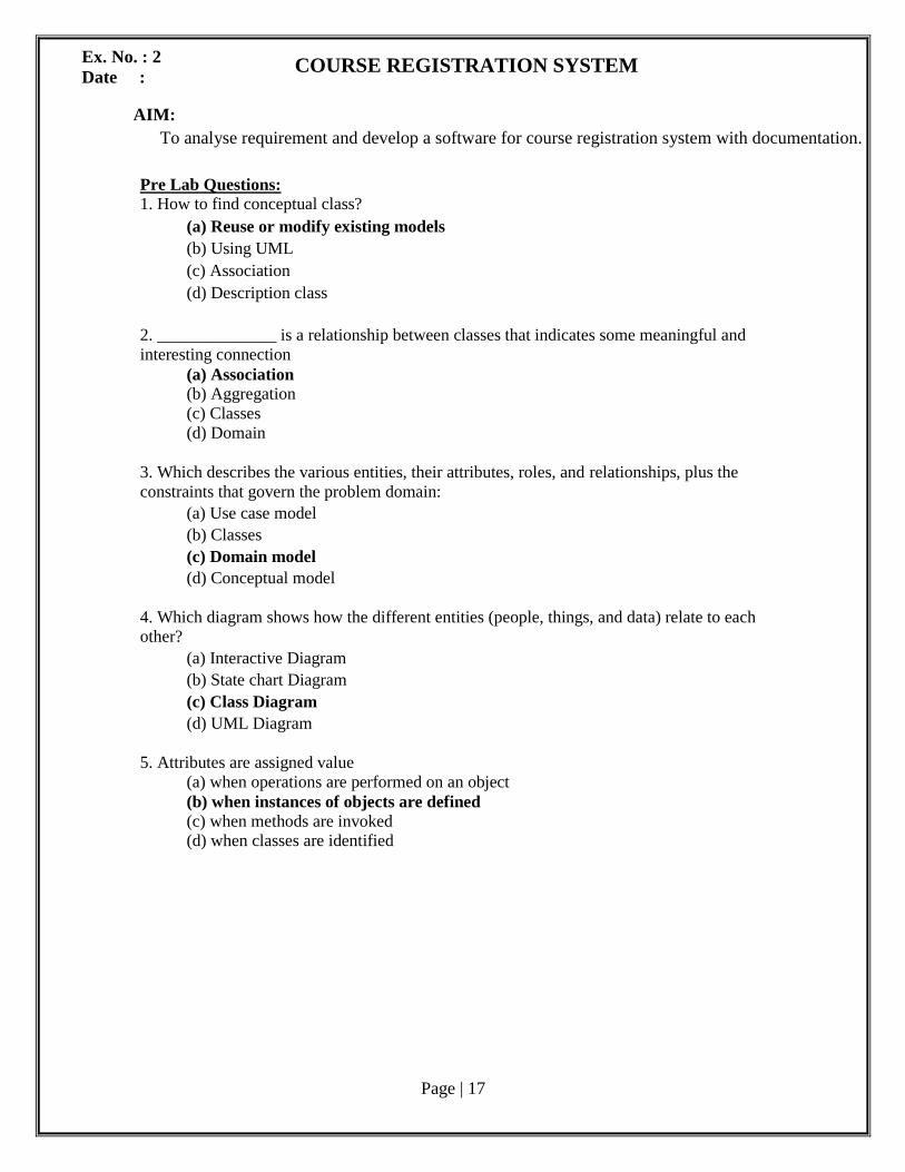
COURSE REGISTRATION SYSTEM
AIM:
To analyse requirement and develop a software for course registration system with documentation.
Pre Lab Questions: 1. How to find conceptual class?
(a) Reuse or modify existing models
(b) Using UML
(c) Association
(d) Description class
2. ______________ is a relationship between classes that indicates some meaningful and
interesting connection
(a) Association
(b) Aggregation
(c) Classes
(d) Domain
3. Which describes the various entities, their attributes, roles, and relationships, plus the
constraints that govern the problem domain:
(a) Use case model
(b) Classes
(c) Domain model
(d) Conceptual model
4. Which diagram shows how the different entities (people, things, and data) relate to each other?
(a) Interactive Diagram
(b) State chart Diagram
(c) Class Diagram
(d) UML Diagram
5. Attributes are assigned value
(a) when operations are performed on an object
(b) when instances of objects are defined (c) when methods are invoked (d) when classes are identified
Ex. No. : 2
Date :
Page | 18
Phase 1: Problem Analysis and Project Planning
i. Thorough study of the problem:
Queue Problem:
In order to register for a course a customer needs to wait in long queues, as all the
customers come to the same spot for registration.
Transport Problem:
A customer has to travel a long distance from far away places to where the University
or the Colleges are located.
Loss of Money:
A lot of money is spent for the journey and for refreshments by the customer while
travelling to the University or College.
Employees Problem:
A lot of Employees has to be recruited in order to handle the large number of
customers.
Need for Branches:
The University or the Colleges needs to open many branches at many places in order
to cover the customer.
Maintenance of Data:
Difficulty in handling large amount of data, as everything is done manually. So,
misplacement of forms and other errors are possible.
Timing not Flexible:
The customer could not register for a course at his/hers feasible timings, as the
University or the College is open only during the office hours.
ii.Identify Project scope, Objectives and Infrastructure
To develop an Online Course Registration System with the objective of enabling students
to register for a course from any part of the world through internet
Hardware Interfaces:
There must be a minimum of 128 MB RAM, 40 GB HDD
Software Interfaces:
The operating system used is windows XP or higher version and Open source
UML Tool ArgoUML.
Operating Environment:
The system works in Windows XP or higher versions.
ArgoUML Tool
Design and Implementation Details:
Hardware limitations: There must be at least 64 MB on-board memory.
Control function: in case of errors and service problems, proper error handling and
data recovery mechanism must be included.
Interface to other applications: not applicable
Parallel operations: not applicable
Signal handshake protocols: not applicable
Page | 19
Reliability requirements: data redundancy and use of special/blank characters must
be avoided.
Safety/security constraint: The application must be excited always normally.
Higher order language requirements: C++ or Java
Phase 2: Software Requirement Analysis
The main purpose of the Software Requirement Analysis is to maintain all functions
and specifications of Online Course Registration System
Software Requirement Specification (SRS):
The purpose of the Software Requirement Specification document is to maintain the
functions and specifications of a particular system. Besides it contains the detailed descriptions of all
the requirements specified
Modules/phases of the project:
1. User should be able to:
Sign-Up if not an already registered user.
Login to the system using a Login-ID and password.
Change the password after logging in, if necessary.
See the vacancy for the courses.
View course details.
Choose the desired and the available course.
Confirm the choice by registering for the course
2. A mail should be sent to the concerned persons e-mail ID about the confirmation of
registration.
3. The Login ID and the Password should be sent to the mentioned e-mail address if a new
account is created.
4. System should automatically show the course details after registering for the particular
course
Page | 20
Phase 3: Data Modeling
Data Dictionary:
The data dictionary is a database that is used to record the complete business
requirement for any system, and the implementation of those requirements into the various
computer systems to service the business needs.
Product Perspective:
The product is independent of other applications but dependent on registration
websites where the user need to login. This dependency exists because of the need for
accessing the user’s details and course details.
Product Functionality:
Signing up and becoming an authenticated User: The user has to give some
personal details to sign up and to become an authenticated user in order to use the
system
Login to the system: Login to the system using his/her Login ID and Password
date. The Server then validates the Login ID and Password and allows the user
access the system.
Check Availability of the course: User could check the availability of the
desired course and then go for the registration of the course.
Selection of course: Based on the availability of the courses the user chooses the
desired course.
Registration: After selecting a particular course the user needs to fill a form to
register for the course.
View course details: After registering for the course, the course details are
displayed to the user.
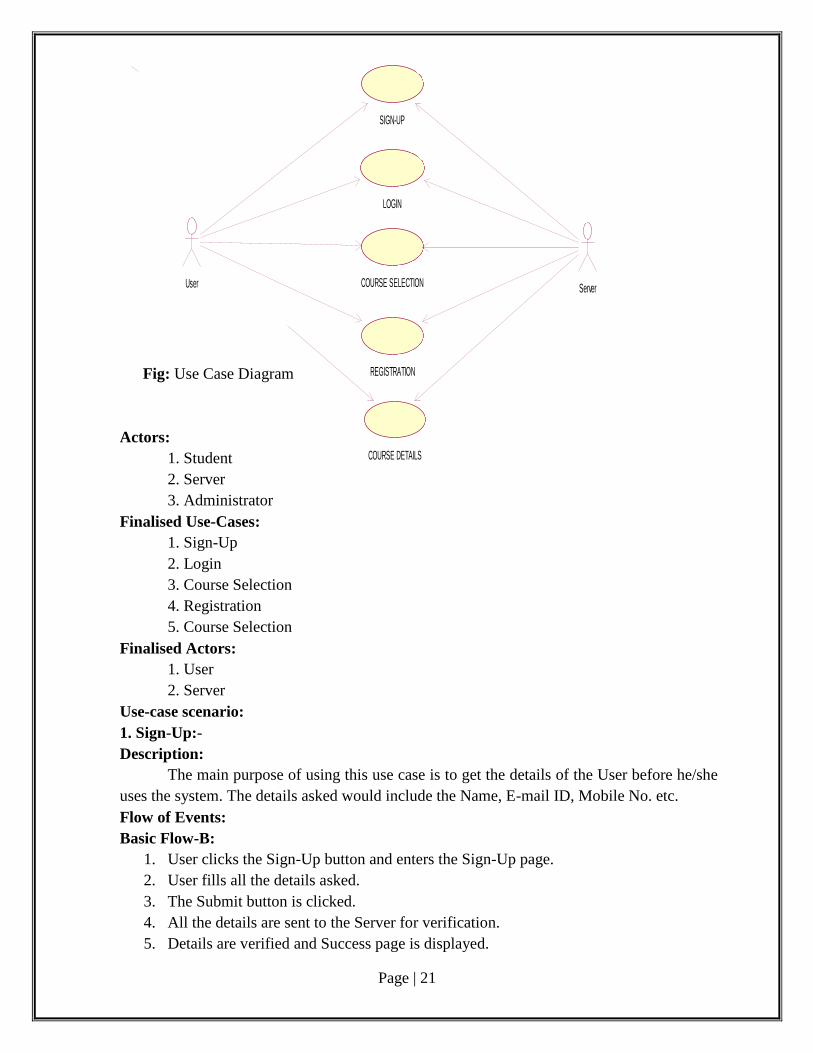
USE CASE DIAGRAM:
Use case diagrams describe what a system does from the standpoint of an external
observer. The emphasis is on what a system does rather than how. Use case diagrams are
closely connected to scenarios. A scenario is an example of what happens when someone
interacts with the system.
Use Case Scenario:
A Use Case Scenario shows the flow of events of use case diagram. The flow of
events are basic flow and alternate flow.
Identifying use-cases and actors:
Use-Cases:
1. Sign-Up
2. Login
3. Check Availability
4. Course Selection
5. Payment
6. Registration
7. Logout
8. Course Details
Page | 21
Server
SIGN-UP
LOGIN
COURSE SELECTION
REGISTRATION
COURSE DETAILS
User
Fig: Use Case Diagram
Actors:
1. Student
2. Server
3. Administrator
Finalised Use-Cases:
1. Sign-Up
2. Login
3. Course Selection
4. Registration
5. Course Selection
Finalised Actors:
1. User
2. Server
Use-case scenario:
1. Sign-Up:-
Description:
The main purpose of using this use case is to get the details of the User before he/she
uses the system. The details asked would include the Name, E-mail ID, Mobile No. etc.
Flow of Events:
Basic Flow-B:
1. User clicks the Sign-Up button and enters the Sign-Up page.
2. User fills all the details asked.
3. The Submit button is clicked.
4. All the details are sent to the Server for verification.
5. Details are verified and Success page is displayed.
Page | 22
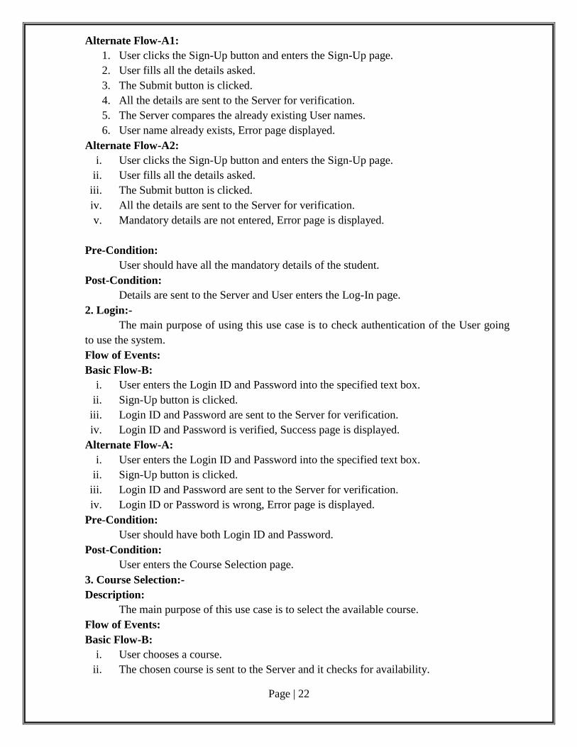
Alternate Flow-A1:
1. User clicks the Sign-Up button and enters the Sign-Up page.
2. User fills all the details asked.
3. The Submit button is clicked.
4. All the details are sent to the Server for verification.
5. The Server compares the already existing User names.
6. User name already exists, Error page displayed.
Alternate Flow-A2:
i. User clicks the Sign-Up button and enters the Sign-Up page.
ii. User fills all the details asked.
iii. The Submit button is clicked.
iv. All the details are sent to the Server for verification.
v. Mandatory details are not entered, Error page is displayed.
Pre-Condition:
User should have all the mandatory details of the student.
Post-Condition:
Details are sent to the Server and User enters the Log-In page.
2. Login:-
The main purpose of using this use case is to check authentication of the User going
to use the system.
Flow of Events:
Basic Flow-B:
i. User enters the Login ID and Password into the specified text box.
ii. Sign-Up button is clicked.
iii. Login ID and Password are sent to the Server for verification.
iv. Login ID and Password is verified, Success page is displayed.
Alternate Flow-A:
i. User enters the Login ID and Password into the specified text box.
ii. Sign-Up button is clicked.
iii. Login ID and Password are sent to the Server for verification.
iv. Login ID or Password is wrong, Error page is displayed.
Pre-Condition:
User should have both Login ID and Password.
Post-Condition:
User enters the Course Selection page.
3. Course Selection:-
Description:
The main purpose of this use case is to select the available course.
Flow of Events:
Basic Flow-B:
i. User chooses a course.
ii. The chosen course is sent to the Server and it checks for availability.
Page | 23
iii. Availability of course is displayed to the User.
iv. Confirmation of course is made.
Alternate Flow-A:
1. User chooses a course.
2. The chosen course is sent to the Server and it checks for availability.
3. Course not available, Error page is displayed.
Pre-Condition:
The User should know which course to select.
Post-Condition:
User enters the registration page.
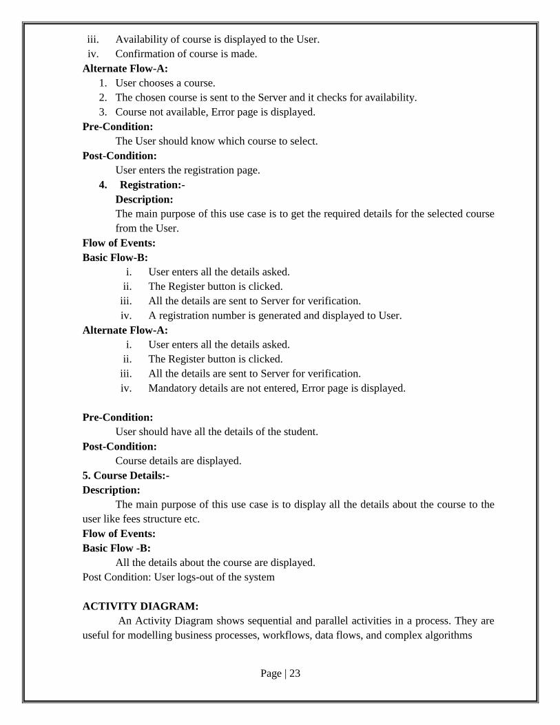
4. Registration:-
Description:
The main purpose of this use case is to get the required details for the selected course
from the User.
Flow of Events:
Basic Flow-B:
i. User enters all the details asked.
ii. The Register button is clicked.
iii. All the details are sent to Server for verification.
iv. A registration number is generated and displayed to User.
Alternate Flow-A:
i. User enters all the details asked.
ii. The Register button is clicked.
iii. All the details are sent to Server for verification.
iv. Mandatory details are not entered, Error page is displayed.
Pre-Condition:
User should have all the details of the student.
Post-Condition:
Course details are displayed.
5. Course Details:-
Description:
The main purpose of this use case is to display all the details about the course to the
user like fees structure etc.
Flow of Events:
Basic Flow -B:
All the details about the course are displayed.
Post Condition: User logs-out of the system
ACTIVITY DIAGRAM:
An Activity Diagram shows sequential and parallel activities in a process. They are
useful for modelling business processes, workflows, data flows, and complex algorithms
Page | 24
Description:
The activity diagram for Online Course Registration System is drawn as shown in the
Figure below. It consists of eight activities and five decisions.
In the first activity the user sign-up’s followed by a decision which checks whether
the user name is available. If ‘yes’ it proceeds to the next step, if ‘no’ the above activity is
performed again. The next step consists of a decision which checks whether all mandatory
details are entered. If ‘yes’ it proceeds to the next step, if ‘no’ the above activity is performed
again.
The next step consists of an activity where the user enters the login page, followed by
another activity where user enters Login ID and Password. The next step consists of a
decision where it checks whether Login ID and Password are authentic. If ‘yes’ it proceeds to
the next step, if no the above activity is performed again.
The next step consists of an activity where the user enters course selection page
followed by another activity where user selects a course. The next step consists of a decision
where it checks whether the selected course is available or not. If available it proceeds to
next step, if no the above activity is performed again.
The next step consists of an activity where the user enters registration page followed
by another activity where user enters the details of the student. The next step consists of a
decision where it checks whether all mandatory details are entered or not. If ‘yes’ it proceeds
to next step, if ‘no’ the above activity is performed again.
The next step consists of an activity where the user views the course details. The
Activity is terminated finally.
Fig: Activity Diagram
Page | 25
CLASS DIAGRAM:
Figure (a) Figure (b)
User Sign-up's
User name
available
Mandatory
Details Entered
No
Enters Login
Page
Yes
Types Login ID and
Password
Login ID and
Password Authentic
Enters Course
Selection Page
Selects Course
Enters Registration
PageCourse Available
Enters Student
Details
Mandatory
Details Entered.
Views Course
Deatils
Yes
No
Yes
No
No
Yes
Yes
No

Page | 26
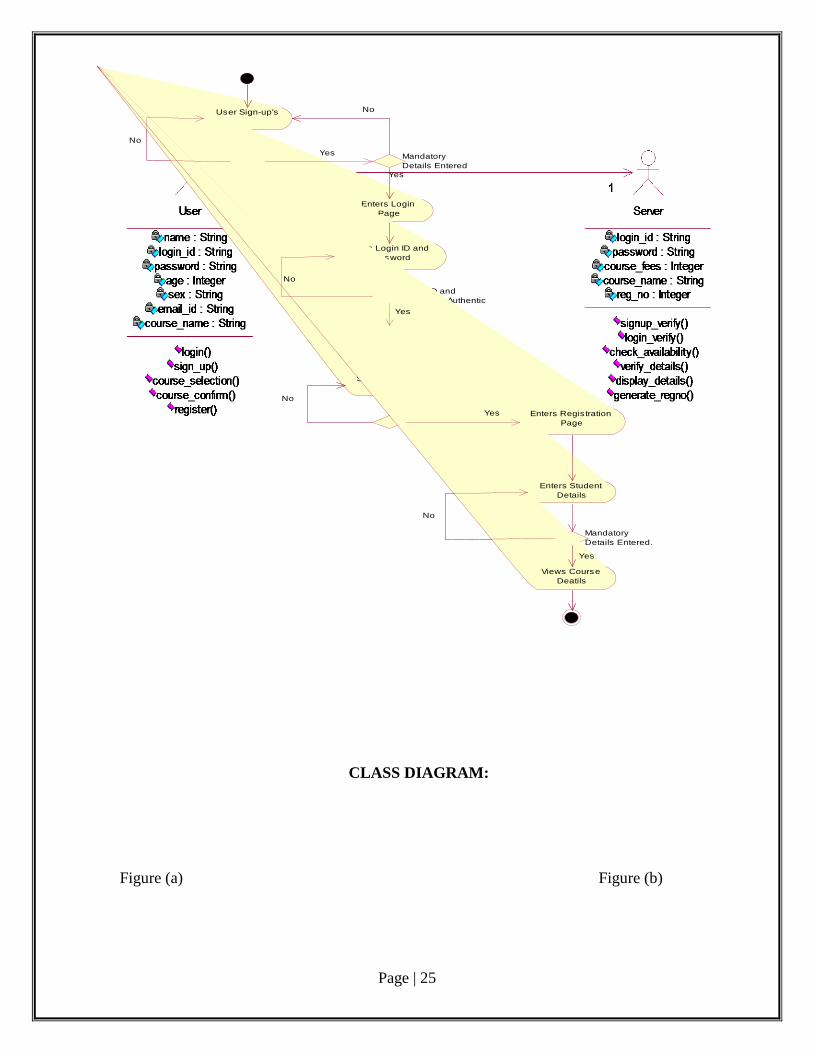
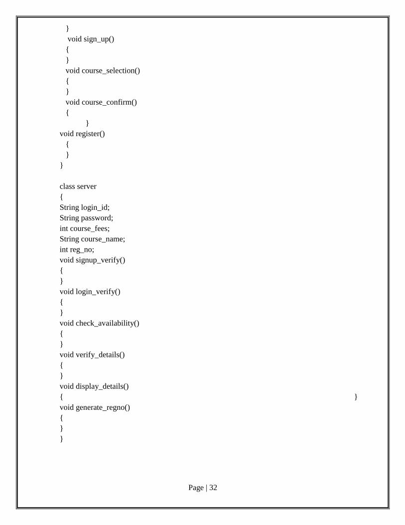
Description:
The class diagram for the Online Course Registration System consists of two classes
‘User’ and ‘Server’ as shown in Figure (a) and Figure (b) respectively.
The ‘User’ class consists of the following attributes and operations:
Attributes: name, login_id, password, sex, email_id and course_name which are of data type
String and age which is of data type Integer.
Operations: login(), sign_up(), course_selection(), course_confirm() and register().
The ‘Server’ class consists of the following attributes and operations:
Attributes: login_id, password and course_name which are of data type String and
course_fees and reg_no which are of data type Integer.
Operations: signup_verify(), login_verify(), check_availability(), verify_details(),
display_details(), generate_regno().
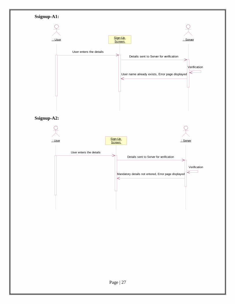
SEQUENCE DIAGRAM:
A Sequence Diagram is a picture that shows, for one particular scenario of a use case,
the events that the external actors generate, their order, and inter-system events. All systems
are treated as a black box; the emphasis of the diagram is events that cross the system
boundary from actors to systems.
Ssignup-B:
: User : ServerSign-Up
Screen:
User enters the details
Details sent to Server for verification
Verification
Details verified and Sucess page displayed
Page | 27
Ssignup-A1:
: User : ServerSign-Up
Screen:
User enters the details
Details sent to Server for verification
Verification
User name already exists, Error page displayed
Ssignup-A2:
: User : ServerSign-Up
Screen:
User enters the details
Details sent to Server for verification
Verification
Mandatory details not entered, Error page displayed
Page | 28
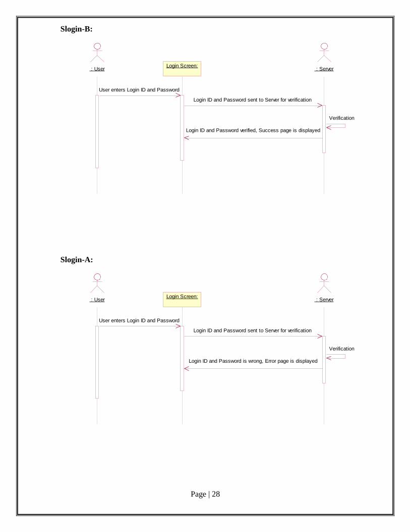
Slogin-B:
: User : ServerLogin Screen:
User enters Login ID and Password
Login ID and Password sent to Server for verification
Verification
Login ID and Password verified, Success page is displayed
Slogin-A:
: User : ServerLogin Screen:
User enters Login ID and Password
Login ID and Password sent to Server for verification
Verification
Login ID and Password is wrong, Error page is displayed
Page | 29
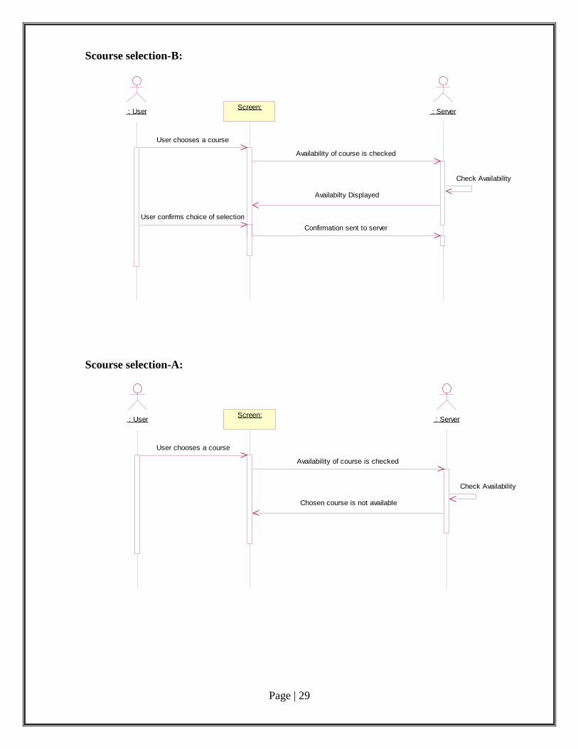
Scourse selection-B:
: User : ServerScreen:
User chooses a course
Availability of course is checked
Check Availability
Availabilty Displayed
User confirms choice of selection
Confirmation sent to server
Scourse selection-A:
: User : ServerScreen:
User chooses a course
Availability of course is checked
Check Availability
Chosen course is not available
Page | 30
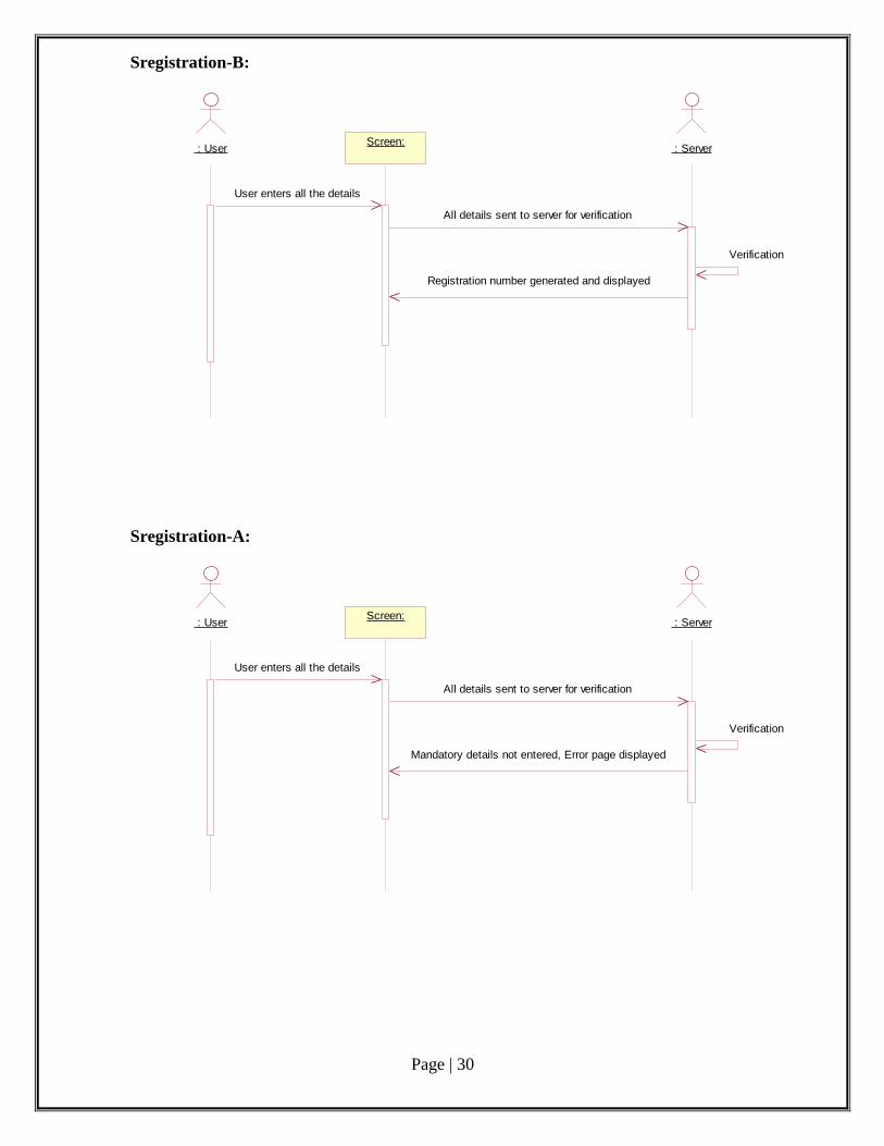
Sregistration-B:
Screen: : User : Server
User enters all the details
All details sent to server for verification
Verification
Registration number generated and displayed
Sregistration-A:
Screen: : User : Server
User enters all the details
All details sent to server for verification
Verification
Mandatory details not entered, Error page displayed
Page | 31
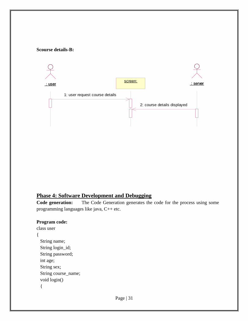
Scourse details-B:
: user : userscreen:screen:
: server : server
1: user request course details
2: course details displayed
Phase 4: Software Development and Debugging
Code generation: The Code Generation generates the code for the process using some
programming languages like java, C++ etc.
Program code:
class user
{
String name;
String login_id;
String password;
int age;
String sex;
String course_name;
void login()
{
Page | 32
}
void sign_up()
{
}
void course_selection()
{
}
void course_confirm()
{
}
void register()
{
}
}
class server
{
String login_id;
String password;
int course_fees;
String course_name;
int reg_no;
void signup_verify()
{
}
void login_verify()
{
}
void check_availability()
{
}
void verify_details()
{
}
void display_details()
{ }
void generate_regno()
{
}
}

Page | 33
Phase 5: Software Testing
Test cases:
A test case is a set of conditions or variables under which a tester will determine
whether a system under test satisfies requirements or works correctly.
Test Plan:
A test plan is a document detailing a systematic approach to testing a system such as a
machine or software. The plan typically contains a detailed understanding of the eventual
workflow.
Validation:
Validation checks that the product design satisfies or fits the intended use (high-level
checking), i.e., the software meets the user requirements. This is done through dynamic
testing and other forms of review.
Code coverage is a measure used to describe the degree to which the source code of a
program is tested by a particular test suite. A program with high code coverage has been
more thoroughly tested and has a lower chance of containing software bugs than a program
with low code coverage.
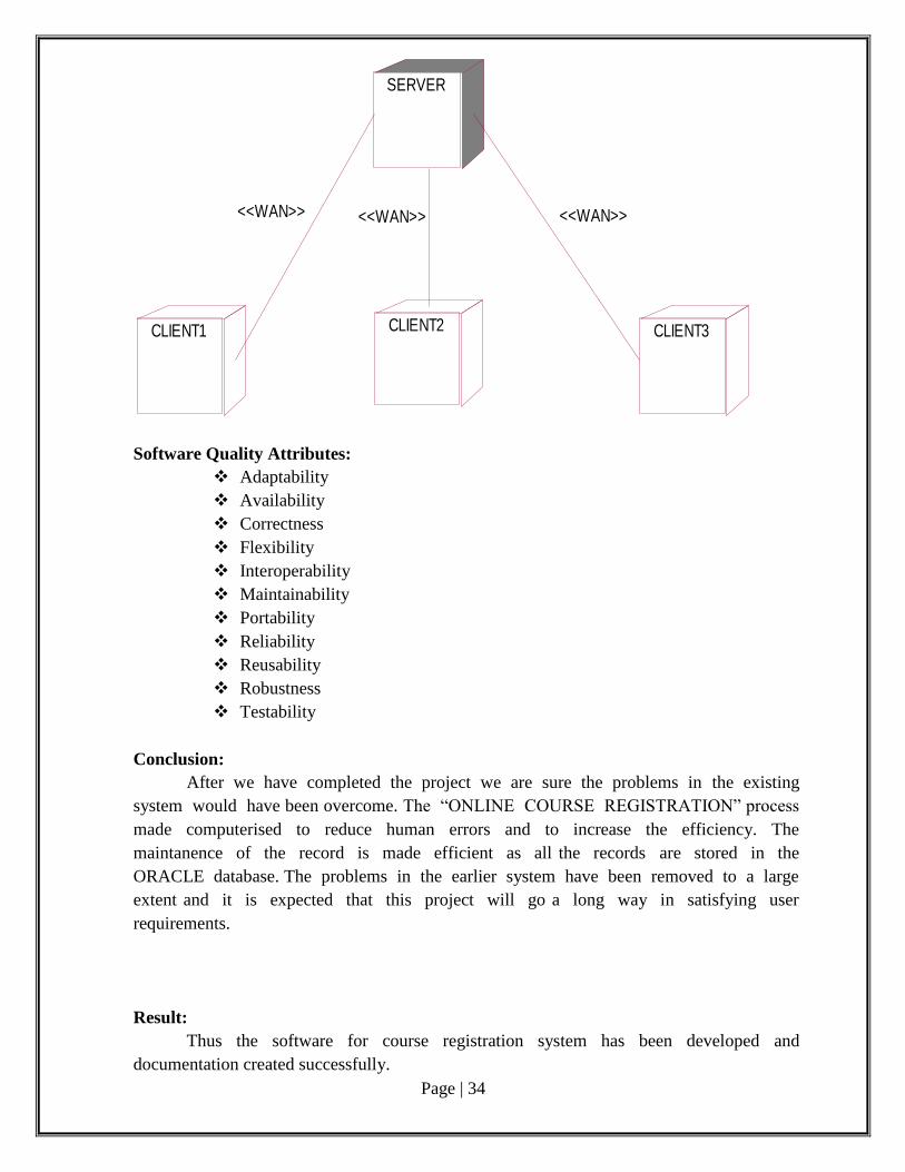
Deployment: A Deployment Diagram shows the assignment of concrete software artefacts to
computational nodes. It shows the deployment of software elements to the physical
architecture and the communication between physical elements.
Description:
The Deployment diagram for Online Course Registration System is drawn as shown
in figure below. The deployment diagram consists of a single processor i.e. the SERVER and
three devices i.e. the three CLIENTS which are connected to the SERVER processor through
Wide Area Connection (WAN) and ‘n’ number of CLIENTS could be connected to the
SERVER through WAN.
Performance Requirements:
More than one user of the system cannot access the system at the same time. The
course selection can be performed under certain constraints or else the system should behave
in a graceful manner. Entering illegal details, accessing personal details of other users should
be prevented.
Safety and Security Requirements:
The User name and Password should match and valid.
The User should provide valid personal information.
Page | 34
Software Quality Attributes:
Adaptability
Availability
Correctness
Flexibility
Interoperability
Maintainability
Portability
Reliability
Reusability
Robustness
Testability
Conclusion:
After we have completed the project we are sure the problems in the existing
system would have been overcome. The “ONLINE COURSE REGISTRATION” process
made computerised to reduce human errors and to increase the efficiency. The
maintanence of the record is made efficient as all the records are stored in the
ORACLE database. The problems in the earlier system have been removed to a large
extent and it is expected that this project will go a long way in satisfying user
requirements.
Result:
Thus the software for course registration system has been developed and
documentation created successfully.
SERVER
CLIENT1 CLIENT2 CLIENT3
<<WAN>> <<WAN>> <<WAN>>
Page | 35
Post lab questions: 1. Which statement is true about elements within the subsystem and public visibility?
a. Only the subset of elements that define the subsystems API should have public visibility.
b. Only the subsystem proxy class should have public visibility.
c. No elements inside the subsystem should have public visibility. d. Only the elements that reference external classes should have public visibility.
2. What are the two types of dependency that can be used from a subsystem? (Choose two.)
a. <<uses>> dependency to a subsystem interface
b. an <<import>> dependency to a package containing used classes c. a <<manifest>> relationship to a node in the Deployment model
d. a <<realize>> relationship to one or more collaboration occurrences
3. Which task is performed during use-case realization refinement?
a. identify participating classes
b. allocate responsibilities among classes
c. model messages between classes
d. model associated class relationships
4. Which statement is true about design subsystems?
a. They partially encapsulate behavior.
b. They represent an independent capability with clear interfaces. c. They model a single implementation variant.
d. They can only contain design classes.
5. Given the following configuration: Package A, which contains class aClass is in the
presentation layer. Package B, which contains a class bClass and an interface bInterface is in
the business layer. Package C, which contains cClass is in the data layer. Which is a poor
practice?
a. aClass calls a method in bClass.
b. aClass has an attribute of type cClass. c. aClass realizes bInterface.
d. bClass realizes bInterface.
Page | 36
STUDENT MARKS ANALYZING SYSTEM
Aim:
To analyze, design and develop code for Student Mark Analysis system using
ArgoUML software.
Prelab Questions:
1. Changes made to an information system to add the desired but not necessarily the
required features is called,
(A) Preventative maintenance.
(B) Adaptive maintenance.
(C) Corrective maintenance.
(D) Perfective maintenance.
2. For a well understood data processing application it is best to use
(A) The waterfall model (B) prototyping model
(C) the evolutionary model (D) the spiral model
3._________ and _________ are the two issues of Requirement Analysis.
a) Performance, Design
b) Stakeholder, Developer
c) Functional, Non-Functional
d) Design , Analysis
4.In the Analysis phase, the development of the ____________ occurs, which is a clear
statement of the goals and objectives of the project.
a) documentation
b) flowchart
c) program specification
d) design
5.Actual programming of software code is done during the ____________ step in the SDLC.
a) Maintenance and Evaluation
b) Design
c) Analysis
d) Development and Documentation
Ex. No. : 3
Date:
Page | 37
Phase 1: Problem Analysis and Project Planning
Problem Statement:
A Problem Statement lists out the problems faced by the process before the
development of the System.
i. Thorough study of the problem:
Student data are increasing lot day by day, mark analysis is the major
FEASIBILITY ANALYSIS
Whatever we think need not be feasible .It is wise to think about the feasibility of
any problem we undertake. Feasibility is the study of impact, which happens in the
organization by the development of a system. The impact can be either positive or negative.
When the positives nominate the negatives, then the system is considered feasible. Here the
feasibility study can be performed in two ways such as technical feasibility and Economical
Feasibility.
Technical Feasibility:
We can strongly says that it is technically feasible, since there will not be much
difficulty in getting required resources for the development and maintaining the system as
well. All the resources needed for the development of the software as well as the
maintenance of the same is available in the organization here we are utilizing the resources
which are available already.
Economical Feasibility
Development of this application is highly economically feasible .The
organization needed not spend much money for the development of t he system already
available. The only thing is to be done is making an environment for the development with
an effective supervision. I f we are doing so, we can attain the maximum usability of the
corresponding resources .Even after the development, the organization will not be in
condition to invest more in the organization. Therefore, the system is economically feasible.
ii.Identify Project scope, Objectives and Infrastructure
1. Objectives The purpose of this document is to define requirements of the Course
Registration System. This Supplementary Specification lists the requirements that are
not readily captured in the use cases of the use case model. The Supplementary
Specifications and the use-case model together capture a complete set of requirements
on the system.
2. Scope
This Supplementary Specification applies to Course Registration System, which will
be developed by the OOAD students.
This Specification defines the non-functional requirements of the system; such as
reliability, usability, performance, and supportability, as well as functional
requirements that are common across a number of use cases.
Page | 38
INFRASTRUCTURE:
HARDWARE REQUIREMENTS
X86 based processor
RAM (128 MB min)
Hard Disc (40 GB)
SOFTWARE REQUIREMENTS
ArgoUML
¨Visual Basic 6.0
Phase 2: Software Requirement Analysis
The purpose of this report is to describe about the logical and systematical functions
of Student Mark Analyzing System. This system will have two breed of users that is staff and
student.
The system will acquire details of student from the faculties and analyzes the obtained data
then declare the results based on the grade criteria’s of the institution.
Where student will play vital role of client that is they just acquire the processed information
from the system database.
The benefaction of this system goes to faculties than clients (students) ,because the staff
doesn’t require any validations, processing on marks of the student they just upload the
marks of the candidates all other task is taken care by the system and also the candidates
doesn’t need to go anywhere to know their results.
The detriment of the system it is in the hand of the staff they must be more careful while
uploading the results since it is manual task to enter the marks it may go invalid or incorrect
which will result invalid results generation and also by students that is accessing the
information of other colleagues .However this system providing the account with proper
authentication if they share there confidential datum (password) with their colleagues.
MODULAR DESCRIPTION
RECORD MARKS MODULE:
This module enables the authenticated users to record the marks and thereby their
respective grades in a database. This is the most important module as it maintains the details
of the marks scored by the students in the database and it is the first and the foremost step in
this system.
VIEW GRADES MODULE:
This module permits the respective users to view their grades as and when necessary
after their identification through their login name and password. This module proves to be
the simplest as it does not allow the user to modify or update any information except viewing
them.
Page | 39
UPDATE MARKS MODULE:
This module enables the authenticated users to update the marks of the students after
each and every test in order to update the data to the present existing grades of the students.
This module just allows the user to modify or update the grades of the students alone but not
their personal details. This module does not allow any user just like that only authenticated
users are allowed to update the necessary data after their identification through their login
name and password.
Phase 3: Data Modeling
1Brief Description The use case describes how a user logs into the Course Registration System.
2 Flow of Events
Basic Flow This use case starts when the user wishes to Login to the Course Registration System
1. The System requests that the user enter his/her name and password
2. The user enters his/her name and password
3. The System validates the entered name and password and logs the user into the System
Alternative Flows Invalid Name/Password
If, in the Basic flow, the user enters an invalid name and/or password, the system displays an
error message. The user chooses to either return to the beginning of the Basic flow or cancel
the login, at which point the use case ends.
Special Requirements
None
Pre-Conditions
None
Post-Conditions
If the use case was successful, the user is now logged into the system. If not, the System
State is unchanged.
Extension Points
None
3. Maintain Professor Information
Brief Description
Page | 40
This use case allows the Registrar to maintain professor information in the
registration system. This includes adding, modifying and deleting professors from the
system.
Flow of Events
Basic Flow This use case starts when the Registrar wishes to add, change, and /or delete professor
information in the system.
1. The system requests that the Registrar specify the function he/she would like to
perform (either Add a Professor, Update a Professor, Or Delete a Professor)
2. Once the Registrar provides the requested information, one of the sub flows is
executed.
If the Registrar selected “Add a professor “, the Add a Professor sub flow is executed.
If the Registrar selected “Update a professor “, the Update a Professor sub flow is
executed.
If the Registrar selected “Delete a professor “, the Delete a Professor sub flow is
executed.
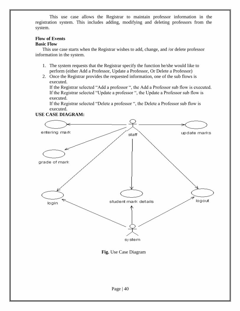
USE CASE DIAGRAM:
Fig. Use Case Diagram
Page | 41
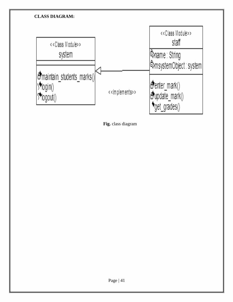
CLASS DIAGRAM:
Fig. class diagram
Page | 42
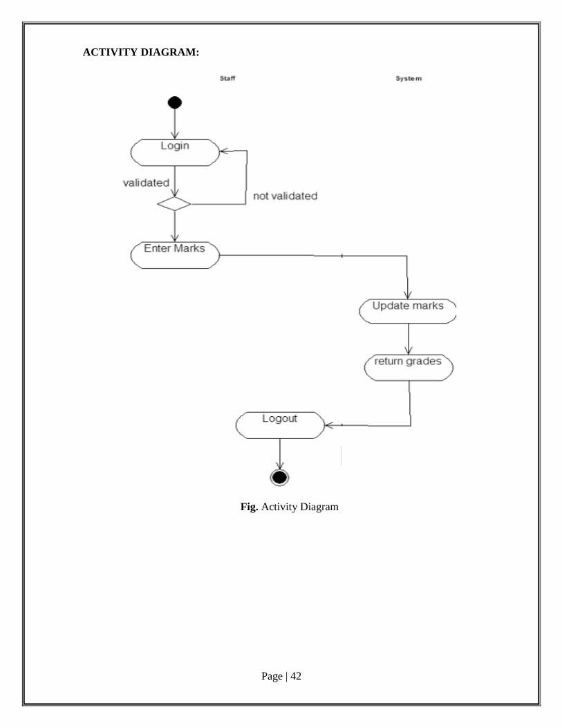
ACTIVITY DIAGRAM:
Fig. Activity Diagram
Page | 43
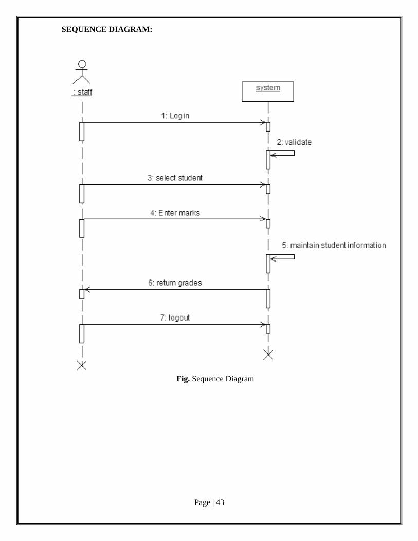
SEQUENCE DIAGRAM:
Fig. Sequence Diagram
Page | 44
Phase 4: Software Development and Debugging
#include<iostream.h>
#include<stdio.h>
#include<dos.h>
class student
{
int roll;
char name[25];
char add [25];
char *city;
public: student()
{
}
void getdata()
{
}
void putdata()
{
}
};
class mrks: public student
{
}
void output()
{
}
void calculate ()
{
}
};
void main()
{
}
}
Page | 45
Phase 5: Software Testing Test cases:
A test case is a set of conditions or variables under which a tester will determine
whether a system under test satisfies requirements or works correctly.
Test Plan:
A test plan is a document detailing a systematic approach to testing a system such as a
machine or software. The plan typically contains a detailed understanding of the eventual
workflow.
Validation:
Validation checks that the product design satisfies or fits the intended use (high-level
checking), i.e., the software meets the user requirements. This is done through dynamic
testing and other forms of review.
Code coverage is a measure used to describe the degree to which the source code of a
program is tested by a particular test suite. A program with high code coverage has been
more thoroughly tested and has a lower chance of containing software bugs than a program
with low code coverage.
RESULT:
Thus the Student marks analyzing system was successfully analyzed, designed,
implemented, verified and tested successfully.

Page | 46
Post Lab Questions
1. Which tool is use for structured designing?
a) Program flowchart
b) Structure chart
c) Data-flow diagram
d) Module
2. A step by step instruction used to solve a problem is known as
a) Sequential structure
b) A List
c) A plan
d) An Algorithm
3.Who designs and implement database structures.
a) Programmers
b) Project managers
c) Technical writers
d) Database administrators
4. Debugging is:
a) creating program code.
b) finding and correcting errors in the program code.
c) identifying the task to be computerized.
d) creating the algorithm.
5. What is the product of the probability of incurring a loss due to the risk and the potential
magnitude of that loss?
a) Risk exposure
b) Risk prioritization
c) Risk analysis
d) All of the mentioned
Page | 47
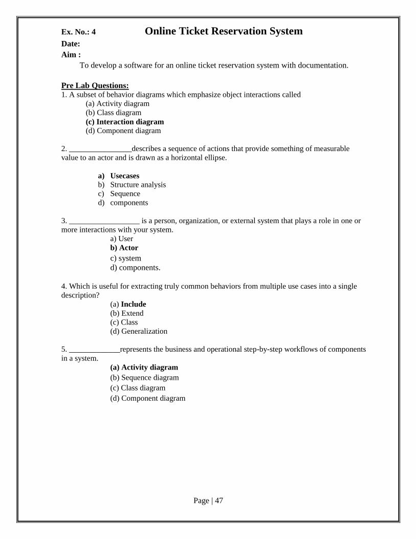
Ex. No.: 4 Online Ticket Reservation System Date:
Aim :
To develop a software for an online ticket reservation system with documentation.
Pre Lab Questions: 1. A subset of behavior diagrams which emphasize object interactions called
(a) Activity diagram
(b) Class diagram
(c) Interaction diagram (d) Component diagram
2. ________________describes a sequence of actions that provide something of measurable
value to an actor and is drawn as a horizontal ellipse.
a) Usecases
b) Structure analysis
c) Sequence
d) components
3. __________________ is a person, organization, or external system that plays a role in one or
more interactions with your system.
a) User
b) Actor
c) system
d) components.
4. Which is useful for extracting truly common behaviors from multiple use cases into a single
description?
(a) Include
(b) Extend
(c) Class
(d) Generalization
5. _____________represents the business and operational step-by-step workflows of components
in a system.
(a) Activity diagram
(b) Sequence diagram
(c) Class diagram
(d) Component diagram
Page | 48
Phase 1: Problem Analysis and Project Planning
Problem statement:
To list out the problems faced by the process of reservation of railway tickets before the
development of the System.
i. Thorough study of the problem:
Queue Problem:
In order to reserve for a ticket a passenger needs to wait in long queues, as all the
passengers come to the same spot for Reservation.
Transport Problem:
A passenger has to travel a long distance from far away places to where the Railway
stations are located.
Loss of Money:
A lot of money is spent for the journey and for refreshments by the passenger while
travelling to the railway station.
Employees Problem:
A lot of Employees has to be recruited in order to handle the large number of
passengers.
Maintenance of Data:
Difficulty in handling large amount of data, as everything is done manually. So,
misplacement of forms and other errors are possible.
Timing Not Flexible:
The passenger could not reserve for a ticket at his/hers feasible timings, as the ticket
counter is open only during the office hours.
ii.Identify Project scope, Objectives and Infrastructure
To develop an online ticket reservation system with the objective of enabling
passengers to reserve for a particular train at the specified time from any part of the country
through internet
The Scope of Online Railway Reservation System is:
1. User should be able to:
Register if not an already registered user.
Login to the system using a Login-ID and password.
Change the password after logging in, if necessary.
Query the rails for two weeks
See current reservations on different rails along with details.
Give details about the credit card.
2. A mail should be sent to the concerned persons e-mail ID about the confirmation of
ticket.
3. The Login ID and the Password should be sent to the mentioned e-mail address if a
new account is created.
Page | 49
4. System should automatically show the fare for the corresponding seat and amount
needs to be pay for selected seats.
Hardware Interfaces:
There must be a minimum of 128 MB RAM, 40 GB HDD
Software Interfaces:
The operating system used is windows XP or higher version and the open source ArgoUML the
database management software is SQL server 2000.
Operating Environment:
The system works in Windows XP or higher versions.
ArgoUML Tool
Design and Implementation Details:
Hardware limitations: There must be at least 64 MB on-board memory.
Control function: in case of errors and service problems, proper error handling and
data recovery mechanism must be included.
Interface to other applications: not applicable
Parallel operations: not applicable
Signal handshake protocols: not applicable
Reliability requirements: data redundancy and use of special/blank characters must
be avoided.
Safety/security constraint: The application must be excited always normally.
Higher order language requirements: C++ or Java
Phase 2: Software Requirement Analysis
Online Railway Reservation System has been developed with the objective of enabling
passenger to reserve for rail ticket from any part of the world through internet.
Document Purpose:
The main purpose of the Software Requirement Specification document is to
maintain all functions and specifications of Online Railway Reservation System.
Intended Audience and Document Overview:
SRS includes two sections: overall descriptions and specific requirements,
Overall Description will describe the major role of the system components and
interconnections.
Specific Requirements will describe the roles and functions of the actors
Definitions, Acronyms and Abbreviations:
Definitions:
Passenger: End user, he/she can reserve for a ticket using a personal computer
connected to the internet.
Page | 50
Server: This is the database where all details are sent for storage and later referred
for other purposes.
Acronyms and Abbreviations:
OS - Operating System
GUI - Graphical User Interface
RAM - Random Access Memory
MB - Mega Bytes
GB - Giga Bytes
HDD - Hard Disk Drives
Product Perspective:
The product is independent of other applications but dependent on registration
websites where the user need to login. This dependency exists because of the need for
accessing the passenger’s details and train details.
Product Functionality:
Registering and becoming an authenticated User: The user has to give some
personal details to sign up and to become an authenticated user in order to use the
system
Login to the system: Login to the system using his/her Login ID and Password
date. The Server then validates the Login ID and Password and allows the user
access the system.
Reservation of ticket: choosing the seats which are available to book. Two weeks
advance reservation is available.
Cancel: The passenger can cancel the ticket by PNR.no provided by the server
while reservation.
Ticket status: Mail should be send to the person about the confirmation of ticket.
Users and Characteristics:
The major user of the system is the passenger. The major user characteristics are:
The end user should have a basic knowledge of internet and Computers.
They shall see the rails information which is belong to current time.
Operating Environment:
The system works in Windows XP or higher versions.
It also needs a SQL server.
Page | 51
Design and Implementation Details:
Hardware limitations: There must be at least 64 MB on-board memory.
Control function: in case of errors and service problems, proper error handling and
data recovery mechanism must be included.
Interface to other applications: not applicable
Parallel operations: not applicable
Reliability requirements: data redundancy and use of special/blank characters must
be avoided.
Safety/security constraint: The application must be excited always normally.
Higher order language requirements: C++ or Java
This is not suitable for visually challenged people.
Assumptions and Dependencies:
The user name and password should match.
The user should have personal details of the passenger who are going to travel.
Specific Requirements:
External Interface Requirements:
User Interfaces:
The user interface of this system is simple and can be understood even by
inexperienced users.
Screen format/organisation: The introductory screen will ask for username and
password. After verification of the details provided by the user, he will be allowed to
access the system and the menu will be displayed.
Window format/organization: Each function will lead to another window. The user
can switch between windows whenever required.
End message: When there are some errors entering invalid data, error message will be
displayed.
Functional Requirements:
The functional requirement of the project includes:
Creating separate account for different Users.
User then logs in to the system using his/her Login ID and Password.
Allowing the Passenger to choose the desired tickets based on availability.
The Passenger then reserve for the ticket by filling a form.
The server then checks the form, to verify if all the mandatory details are entered.
Finally the Ticket details are displayed to the User by the Server.
Other Functional Requirements:
Performance Requirements:
More than one user of the system cannot access the system at the same time. The
ticket reservation can be performed under certain constraints or else the system should
behave in a graceful manner. Entering illegal details, accessing personal details of other
passengers should be prevented.
Page | 52
Safety and Security Requirements:
The User name and Password should match and valid.
The User should provide valid personal information.
Software Quality Attributes:
Adaptability
Availability
Correctness
Flexibility
Interoperability
Maintainability
Portability
Reusability
Testability
Phase 3: Data Modelling
To identify the possible use cases for the Online Railway Reservation System and then
finalise it.
Use Cases (Rough):
1. Register
2. Login
3. Train Details
4. Reservation
5. Ticket Status
6. Cancel
7. Print Ticket
8. Logout
Actors:
1. Passenger
2. Server
3. Administrator
Finalised Use Cases:
1. Register
2. Login
3. Reservation
4. Cancel
5. Ticket Status
Finalised Actors:
1. Passenger
2. Server
Page | 53
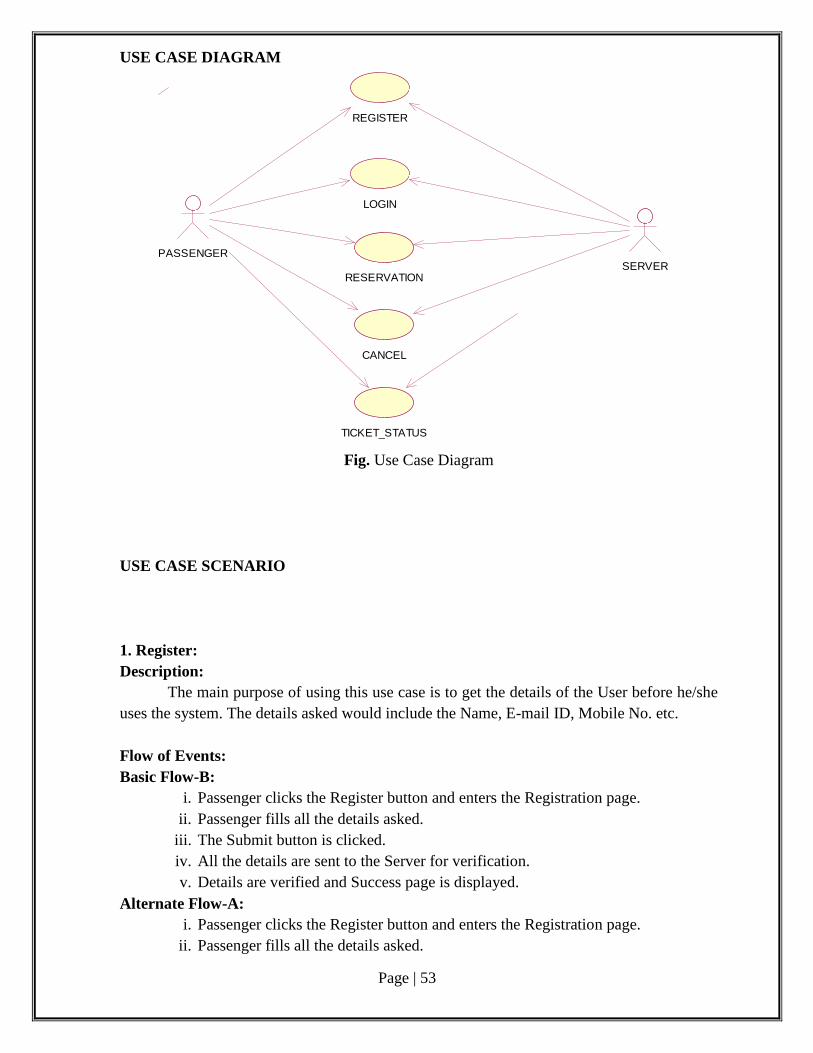
USE CASE DIAGRAM
PASSENGER
REGISTER
LOGIN
RESERVATION
CANCEL
SERVER
TICKET_STATUS
Fig. Use Case Diagram
USE CASE SCENARIO
1. Register:
Description:
The main purpose of using this use case is to get the details of the User before he/she
uses the system. The details asked would include the Name, E-mail ID, Mobile No. etc.
Flow of Events:
Basic Flow-B:
i. Passenger clicks the Register button and enters the Registration page.
ii. Passenger fills all the details asked.
iii. The Submit button is clicked.
iv. All the details are sent to the Server for verification.
v. Details are verified and Success page is displayed.
Alternate Flow-A:
i. Passenger clicks the Register button and enters the Registration page.
ii. Passenger fills all the details asked.
Page | 54
iii. The Submit button is clicked.
iv. All the details are sent to the Server for verification.
v. The Server compares the already existing User names.
vi. User name already exists, Error page displayed.
Alternate Flow-A1:
a. Passenger clicks the Register button and enters the Registration page.
b. Passenger fills all the details asked.
c. The Submit button is clicked.
d. All the details are sent to the Server for verification.
e. Mandatory details are not entered, Error page is displayed.
Pre-Condition:
User should have all the mandatory details of the Passenger.
Post-Condition:
Details are sent to the Server and User enters the Log-In page.
2. Login:
The main purpose of using this use case is to check authentication of the Passenger
going to use the system.
Flow of Events:
Basic Flow-B:
v. Passenger enters the Login ID and Password into the specified text box.
vi. Login button is clicked.
vii. Login ID and Password are sent to the Server for verification.
viii. Login ID and Password is verified, Success page is displayed.
Alternate Flow-A:
v. User enters the Login ID and Password into the specified text box.
vi. Login button is clicked.
vii. Login ID and Password are sent to the Server for verification.
viii. Login ID or Password is wrong, Error page is displayed.
Pre-Condition:
Passenger should have both Login ID and Password.
Post-Condition:
Passenger enters the Reservation page.
3. Reservation:-
Description:
The main purpose of this use case is to reserve the ticket in train.
Flow of Events:
Basic Flow-B:
v. Passenger should click the reservation icon.
vi. Server provides the reservation form.
vii. Passenger fills the form and clicks submit button
viii. Server will verify the details and store it.
Page | 55
ix. Server will now provide the PNR.NO to Passenger
Alternate Flow-A:
i. Passenger clicks the reservation page
ii. Server provides the reservation form.
iii. If the Passenger gives invalid credit card number an error page displays.
Pre-Condition:
The Passenger has to decide about whether he/she is going to travel.
Post-Condition:
Passenger will get the ticket.
4. Cancel:-
Description:
The main purpose of this use case helps the Passenger to cancel the ticket which
he/she has booked earlier.
Flow of Events:
Basic Flow-B:
v. Passenger cancels the ticket by typing the PNR.NO on the cancellation form.
vi. Server requests its database to search for the PNR.NO.
vii. Server will cancel the ticket and request database to delete the passenger
reservation information.
viii. Server will send the conformation message about the cancellation.
Alternate Flow-A:
v. Passenger cancels the ticket by typing the PNR.NO on the cancellation form.
vi. If the Passenger enters the invalid PNR.NO, an error message will display.
vii. Server asked the Passenger to enter valid PNR.NO
Pre-Condition:
Passenger should have booked the ticket earlier.
Post-Condition:
Entering the PNR.NO will cancel the ticket.
5. Course Details:-
Description:
The main purpose of this use case is to know the satus of the ticket by entering the
PNR.NO
Flow of Events:
Basic Flow -B:
i. Passenger should give the PNR.NO to know the status of the ticket which
he/she booked earlier.
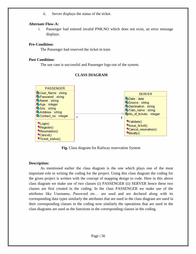
Page | 56
ii. Server displays the status of the ticket.
Alternate Flow-A:
i. Passenger had entered invalid PNR.NO which does not exist, an error message
displays.
Pre-Condition:
The Passenger had reserved the ticket in train
Post Condition:
The use case is successful and Passenger logs-out of the system.
CLASS DIAGRAM
Fig. Class diagram for Railway reservation System
Description:
As mentioned earlier the class diagram is the one which plays one of the most
important role in writing the coding for the project. Using this class diagram the coding for
the given project is written with the concept of mapping design to code. Here in this above
class diagram we make use of two classes (i) PASSENGER (ii) SERVER hence these two
classes are first created in the coding. In the class PASSENGER we make use of the
attributes like Username, Password etc… are used and are declared along with its
corresponding data types similarly the attributes that are used in the class diagram are used in
their corresponding classes in the coding now similarly the operations that are used in the
class diagrams are used as the functions in the corresponding classes in the coding.

Page | 57
Phase 4: Software Development and Debugging
Program code:
class Passenger
{
String name;
String login_id;
String password;
int age;
String sex;
String address;
int contact_no
void register()
{
}
void log_in()
{
}
void reservation()
{
}
void cancel()
{
}
void ticket_status()
{
}
` }
class Server
{
String source;
String destination;
String train_name;
int no_of_tickets;
void validate()
{
}
void issue_ticket()
{
}
Page | 58
void cancel_reservation()
{
}
void modify()
{
}
}
Phase 5: Software Testing
Test cases:
A test case is a set of conditions or variables under which a tester will determine
whether a system under test satisfies requirements or works correctly.
Test Plan:
A test plan is a document detailing a systematic approach to testing a system such as a
machine or software. The plan typically contains a detailed understanding of the eventual
workflow.
Validation:
Validation checks that the product design satisfies or fits the intended use (high-level
checking), i.e., the software meets the user requirements. This is done through dynamic
testing and other forms of review.
Code coverage is a measure used to describe the degree to which the source code of a
program is tested by a particular test suite. A program with high code coverage has been
more thoroughly tested and has a lower chance of containing software bugs than a program
with low code coverage.
DEPLOYMENT DIAGRAM:
To visualize the topology of the physical components of a system where the software
components are deployed.
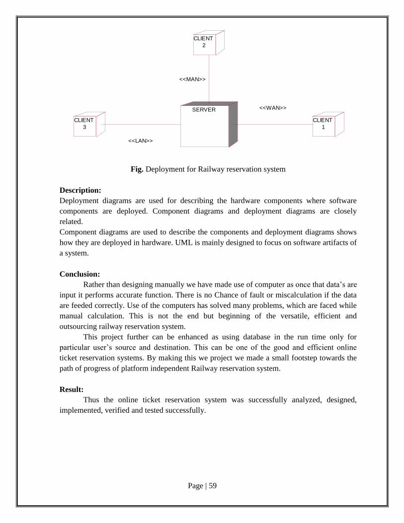
Page | 59
Fig. Deployment for Railway reservation system
Description:
Deployment diagrams are used for describing the hardware components where software
components are deployed. Component diagrams and deployment diagrams are closely
related.
Component diagrams are used to describe the components and deployment diagrams shows
how they are deployed in hardware. UML is mainly designed to focus on software artifacts of
a system.
Conclusion:
Rather than designing manually we have made use of computer as once that data’s are
input it performs accurate function. There is no Chance of fault or miscalculation if the data
are feeded correctly. Use of the computers has solved many problems, which are faced while
manual calculation. This is not the end but beginning of the versatile, efficient and
outsourcing railway reservation system.
This project further can be enhanced as using database in the run time only for
particular user’s source and destination. This can be one of the good and efficient online
ticket reservation systems. By making this we project we made a small footstep towards the
path of progress of platform independent Railway reservation system.
Result:
Thus the online ticket reservation system was successfully analyzed, designed,
implemented, verified and tested successfully.
SERVER
CLIENT
1
CLIENT
2
CLIENT
3
<<LAN>>
<<MAN>>
<<WAN>>
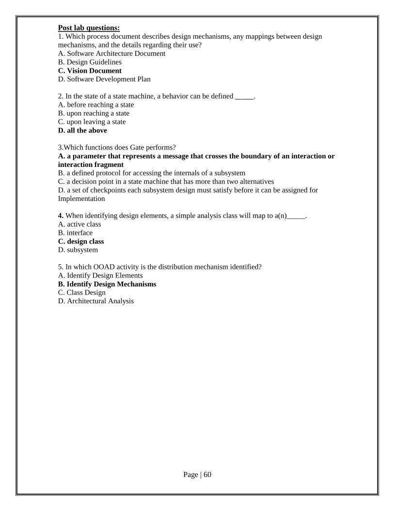
Page | 60
Post lab questions: 1. Which process document describes design mechanisms, any mappings between design
mechanisms, and the details regarding their use?
A. Software Architecture Document
B. Design Guidelines
C. Vision Document
D. Software Development Plan
2. In the state of a state machine, a behavior can be defined _____.
A. before reaching a state
B. upon reaching a state
C. upon leaving a state
D. all the above
3.Which functions does Gate performs?
A. a parameter that represents a message that crosses the boundary of an interaction or
interaction fragment B. a defined protocol for accessing the internals of a subsystem
C. a decision point in a state machine that has more than two alternatives
D. a set of checkpoints each subsystem design must satisfy before it can be assigned for
Implementation
4. When identifying design elements, a simple analysis class will map to a(n)_____.
A. active class
B. interface
C. design class D. subsystem
5. In which OOAD activity is the distribution mechanism identified?
A. Identify Design Elements
B. Identify Design Mechanisms C. Class Design
D. Architectural Analysis
Page | 61
Platform assignment system for the trains in a railway station
Aim:
To develop software for Platform assignment system for the trains in a railway station.
Pre Lab Questions:
1.Alpha and Beta Testing are forms of
(A) Acceptance testing (B) Integration testing
(C) System Testing (D) Unit testing
2.Aggregation represents
(A) is_a relationship (B) part_of relationship
(C) composed_of relationship (D) none of above
3.The main purpose of integration testing is to find
(A) design errors (B) analysis errors
(C) procedure errors (D) interface errors
4.Software consists of
(A) Set of instructions + operating procedures
(B) Programs + documentation + operating procedures
(C) Programs + hardware manuals
(D) Set of programs
5.Software feasibility is based on which of the following
(A) business and marketing concerns
(B) scope, constraints, market
(C) technology, finance, time, resources
(D) technical prowess of the developers
Phase 1: Problem Analysis and Project Planning Problem Statement:
A Problem Statement lists out the problems faced by the process before the
development of the System.
i. Thorough study of the problem:
Following are the constraints of the earlier system:
Controller was essentially a recorder rather than managing the train movements
Information was not available immediately regarding unusual incidents at field
Decision/action taken was delayed
Decisions taken were ad-hoc
The information displaying on indicator display may not math with actual train-
running information
Delay in announcements
ii.Identify Project scope, Objectives and Infrastructure
Ex. No. : 5
Date :
Page | 62
We consider a station in which several trains might stop at the same platform at the
same time. The trains might enter and leave the station to both sides, but the arrival and
departure times and directions are fixed according to a given time table. The objective is to
assign platforms to the trains such that they can enter and leave the station in time without
being blocked by any other train.
We consider the following problem. We are given a set of trains that has to enter a
station with Marshalling topology. Each train might enter the station either from the left hand
side or from the right hand side and might leave the station to the left hand side or to the right
hand side. The direction from which it enters the station and in which it leaves the station,
however, is fixed. Also the arrival time and departure time is fixed. Hence, each train is
labeled with the time interval in which it stays in the station, and an entering and leaving
direction respectively. For example, a train labeled [24,25]RL is a train that enters the station
at 24 from the right hand side and leaves the station at 25 to the left hand side. In the
meanwhile, it stops on one of several parallel platforms (tracks) in the station. There might
be several trains waiting at the same platform. We further assume that the platforms have
infinite length. The problem is to assign each train to a platform such that it can leave the
station in time without being blocked by other trains.
Hard disk: The database connectivity requires a hardware configuration that is on-line. This
makes it necessary to have a fast database system (such as any RDBMS) running on high rpm
hard-disk permitting complete data redundancy and backup systems to support the primary goal
of reliability.
The system must interface with the standard output device, keyboard and mouse to interact with
this software.
Software interfaces:
Back End: MS Access 2007
Front End: Microsoft Visual Basic 6.0
Operating Environment:
The system works in Windows XP or higher versions.
ArgoUML Tool
Phase 2: Software Requirement Analysis The main purpose of the Software Requirement Analysis is to maintain all functions
and specifications of an ATM System.
Software Requirement Specification (SRS):
The purpose of the Software Requirement Specification document is to maintain the functions
and specifications of a particular system. Besides it contains the detailed descriptions of all the
requirements specified
Modules/phases of the project:
To develop a platform assignment system to perform the following functions:
On-line display of movements of all trains with train numbers/rake numbers on video
monitors as well as over view indication panel, located in control room
Interfacing with the train indicator boards at various stations for minute to minute
train arrival information to commuters
Provision of video display units for running information to commuters with count
down in minutes
Page | 63
Phase 3: Data Modelling
Product Perspective:
The product is independent of other applications but dependent on the type of ATM
System where the user need to login. This dependency exists because of the need for
accessing the user’s savings details.
Use Case Diagram:
Use case diagrams describe what a system does from the standpoint of an external
observer. The emphasis is on what a system does rather than how. Use case diagrams are
closely connected to scenarios. A scenario is an example of what happens when someone
interacts with the system.
Use Case Scenario:
A Use Case Scenario shows the flow of events of use case diagram. The flow of
events are basic flow and alternate flow.
Identifying use-cases and actors: Creating a New Account
The user should provide his personal details to facilitate the bank clerk to create a new account.
Identified use cases
i. Login: Here the user enters the card and the inputs his password to enter into the main form.
If the password is incorrect, the system will display an error message.
ii. Maintaining Customer Information: Here the administrator plays an important role, whose work is to add customer, delete
customer account, update customer account, etc.
Identified Actors
i Administrator: Administrator plays an important role. He is the system designer. All the updating
works is done by him only like adding, deleting customer accounts.
ii Database: All the transaction works-withdrawal and deposit are updated in the database.
iii Customer: He is the external user to check the platform details.
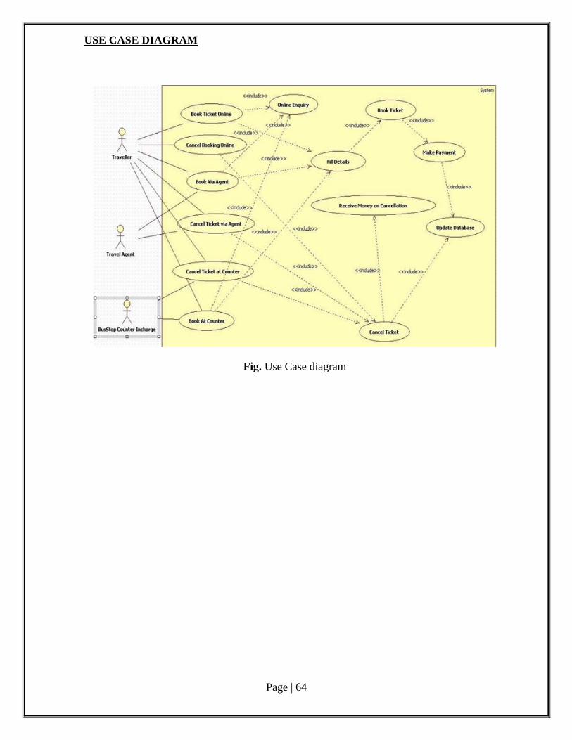
Page | 64
USE CASE DIAGRAM
Fig. Use Case diagram
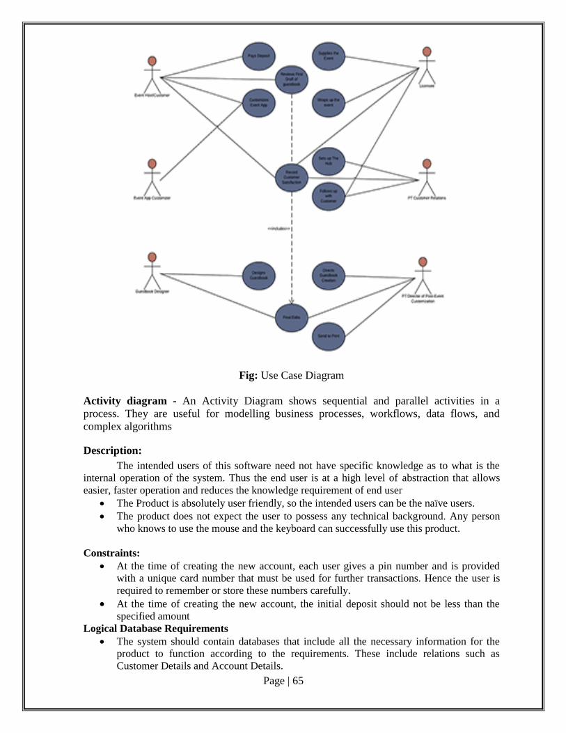
Page | 65
Fig: Use Case Diagram
Activity diagram - An Activity Diagram shows sequential and parallel activities in a
process. They are useful for modelling business processes, workflows, data flows, and
complex algorithms
Description:
The intended users of this software need not have specific knowledge as to what is the
internal operation of the system. Thus the end user is at a high level of abstraction that allows
easier, faster operation and reduces the knowledge requirement of end user
The Product is absolutely user friendly, so the intended users can be the naïve users.
The product does not expect the user to possess any technical background. Any person
who knows to use the mouse and the keyboard can successfully use this product.
Constraints:
At the time of creating the new account, each user gives a pin number and is provided
with a unique card number that must be used for further transactions. Hence the user is
required to remember or store these numbers carefully.
At the time of creating the new account, the initial deposit should not be less than the
specified amount Logical Database Requirements
The system should contain databases that include all the necessary information for the
product to function according to the requirements. These include relations such as
Customer Details and Account Details.
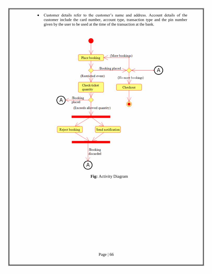
Page | 66
Customer details refer to the customer’s name and address. Account details of the
customer include the card number, account type, transaction type and the pin number
given by the user to be used at the time of the transaction at the bank.
Fig: Activity Diagram
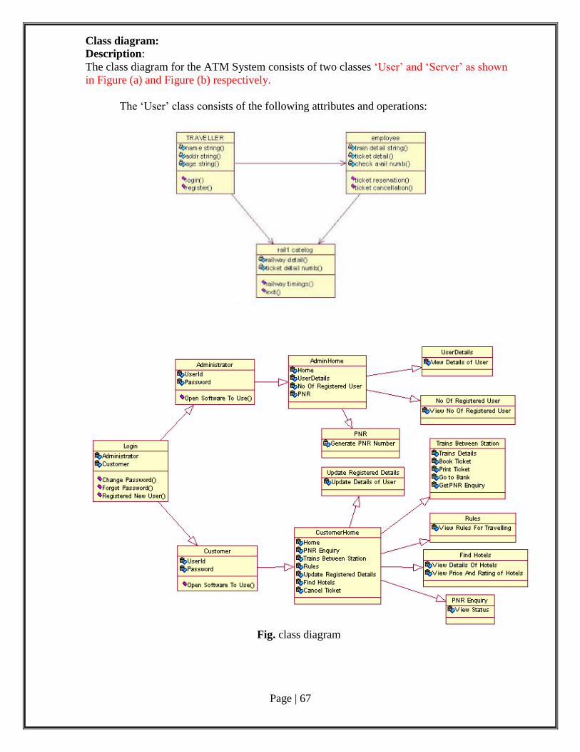
Page | 67
Class diagram: Description:
The class diagram for the ATM System consists of two classes ‘User’ and ‘Server’ as shown
in Figure (a) and Figure (b) respectively.
The ‘User’ class consists of the following attributes and operations:
Fig. class diagram
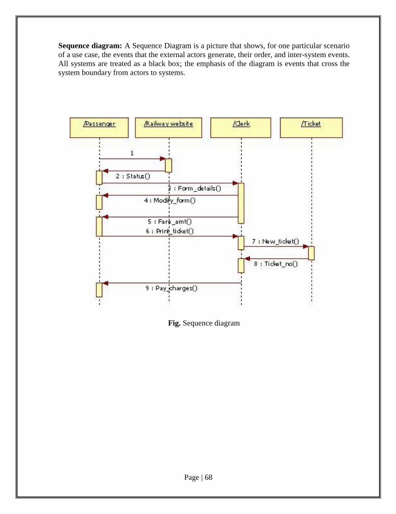
Page | 68
Sequence diagram: A Sequence Diagram is a picture that shows, for one particular scenario
of a use case, the events that the external actors generate, their order, and inter-system events.
All systems are treated as a black box; the emphasis of the diagram is events that cross the
system boundary from actors to systems.
Fig. Sequence diagram
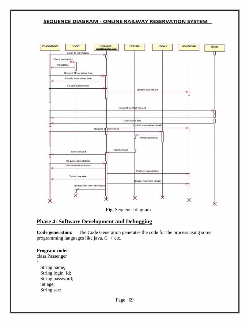
Page | 69
Fig. Sequence diagram
Phase 4: Software Development and Debugging
Code generation: The Code Generation generates the code for the process using some
programming languages like java, C++ etc.
Program code: class Passenger
{
String name;
String login_id;
String password;
int age;
String sex;
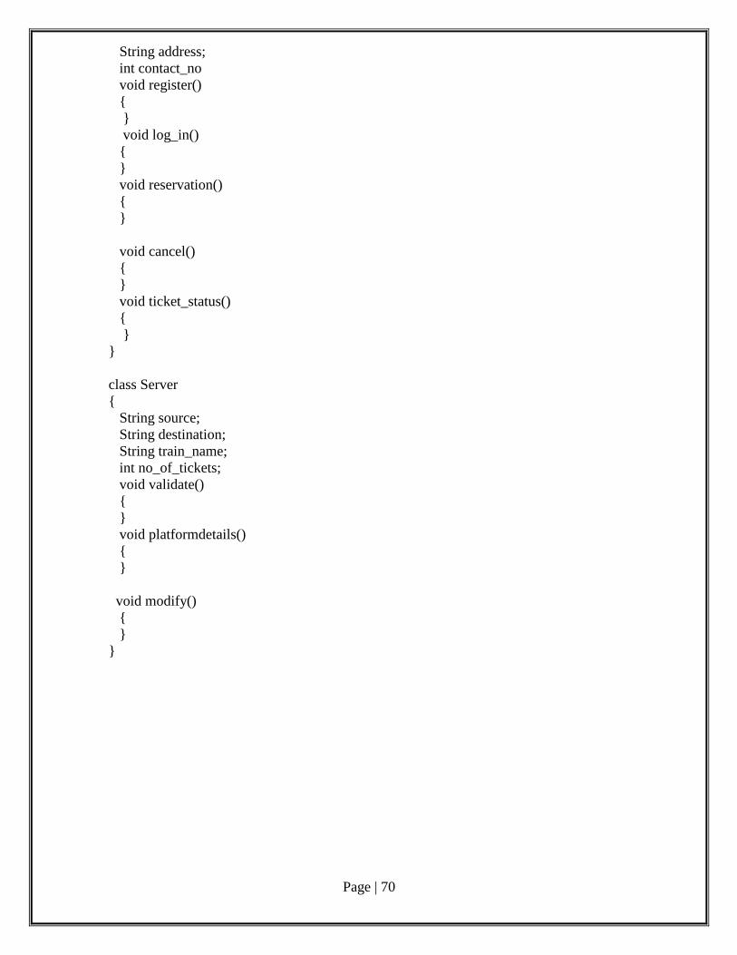
Page | 70
String address;
int contact_no
void register()
{
}
void log_in()
{
}
void reservation()
{
}
void cancel()
{
}
void ticket_status()
{
}
}
class Server
{
String source;
String destination;
String train_name;
int no_of_tickets;
void validate()
{
}
void platformdetails()
{
}
void modify()
{
}
}
Page | 71
Phase 5: Software Testing Test cases:
A test case is a set of conditions or variables under which a tester will determine
whether a system under test satisfies requirements or works correctly.
Test Plan:
A test plan is a document detailing a systematic approach to testing a system such as a
machine or software. The plan typically contains a detailed understanding of the eventual
workflow.
Validation:
Validation checks that the product design satisfies or fits the intended use (high-level
checking), i.e., the software meets the user requirements. This is done through dynamic
testing and other forms of review.
Code coverage is a measure used to describe the degree to which the source code of a
program is tested by a particular test suite. A program with high code coverage has been
more thoroughly tested and has a lower chance of containing software bugs than a program
with low code coverage.
Deployment: A Deployment Diagram shows the assignment of concrete software artefacts
to computational nodes. It shows the deployment of software elements to the physical
architecture and the communication between physical elements
Result:
Thus the software for platform assignment system has been developed and
documentation created successfully.
Page | 72
Post Lab questions:
1. The step-by-step instructions that solve a problem are called _____.
A. An algorithm
B. A list
C. A plan
D. A sequential structure
E. None of the above
2. The expansion of the acronym CRC is
a. Collecting Responsibilities Classes
b. Collaborating with Relevant Classes
c. Class Responsibilities and Collaborators
d. Creating Relevant Classes
3. Encapsulation in object-oriented modelling is useful as
a. it allows improving methods of an object independent of other parts of
system
b. it hides implementation details of methods
c. it allows easy designing
d. encapsulates attributes and operations of object
4. Inheritance in object-oriented system is used to
a. create new classes from existing classes
b. add new operations to existing operations
c. add new attributes to existing attributes
d. add new states to existing states
5. Which of the following is not a factor in the failure of the systems developments projects?
A. size of the company
B. inadequate user involvement
C. failure of systems integration
D. continuation of a project that should have been cancelled
E. None of the above
Page | 73
Expert system to prescribe the medicines
for the given symptoms Aim:
To develop software for Expert system to prescribe the medicines for the given symptoms
Pre Lab Questions:
1. Which statement is true about elements within the subsystem and public visibility?
A. Only the subset of elements that define the subsystems API should have public visibility.
B. Only the subsystem proxy class should have public visibility.
C. No elements inside the subsystem should have public visibility.
D. Only the elements that reference external classes should have public visibility.
2. Which task is performed during use-case realization refinement?
A. identify participating classes
B. allocate responsibilities among classes
C. model messages between classes
D. model associated class relationships
3. Which statement is true about design subsystems?
A. They partially encapsulate behavior.
B. They represent an independent capability with clear interfaces.
C. They model a single implementation variant.
D. They can only contain design classes.
4, Which process document describes design mechanisms, any mappings between design
mechanisms, and the details regarding their use?
A. Software Architecture Document
B. Design Guidelines
C. Vision Document
D. Software Development Plan
5. In which OOAD activity is the distribution mechanism identified?
A. Identify Design Elements
B. Identify Design Mechanisms
C. Class Design
D. Architectural Analysis
Ex. No. : 6
Date:
Page | 74
Phase 1: Problem Analysis and Project Planning
Problem Statement:
A Problem Statement lists out the problems faced by the process before the
development of the System.
i. Thorough study of the problem:
The medical expert provides the user to which they are put, and the relative positions of the
developer, physician, and patient, strict tort liability should adhere to the developer.
The existing system has few limitations which make it difficult to use. The limitation of the
existing system is that the system is to get treatment only by consulting the doctors. The
system does not have facilities to update. In the existing system details cannot be modified
often. The present system is inefficient and time consuming. Only one appointment cannot be
changed. The prescription is not specified after consulting in database. The receptionist
cannot give proper details of appointment.
ii.Identify Project scope, Objectives and Infrastructure
The objective of the present system is that the consultant through the system by
providing sufficient information. New appointments can be added to the database. The
proposed system is used by the hospitals to give the details description of disease and the
treatment with respect to disease. The system is programmed is such a way that each time
appointment time is over the database updates automatically. The proposed system that is
being developed is user friendly system. The processing speed is very high when compared
to the existing system. The space occupied by the proposed system in the memory is also
very less. The doctor details can be known. There is review of details of disease treatment.
The appointment can be made
Hard disk: The database connectivity requires a hardware configuration that is on-line. This
makes it necessary to have a fast database system (such as any RDBMS) running on high rpm
hard-disk permitting complete data redundancy and backup systems to support the primary goal
of reliability.
The system must interface with the standard output device, keyboard and mouse to interact with
this software.
Software interfaces:
Back End: MS Access 2007
Front End: Microsoft Visual Basic 6.0
Operating Environment:
The system works in Windows XP or higher versions.
ArgoUML Tool
Phase 2: Software Requirement Analysis The main purpose of the Software Requirement Analysis is to maintain all functions
and specifications of an ATM System.
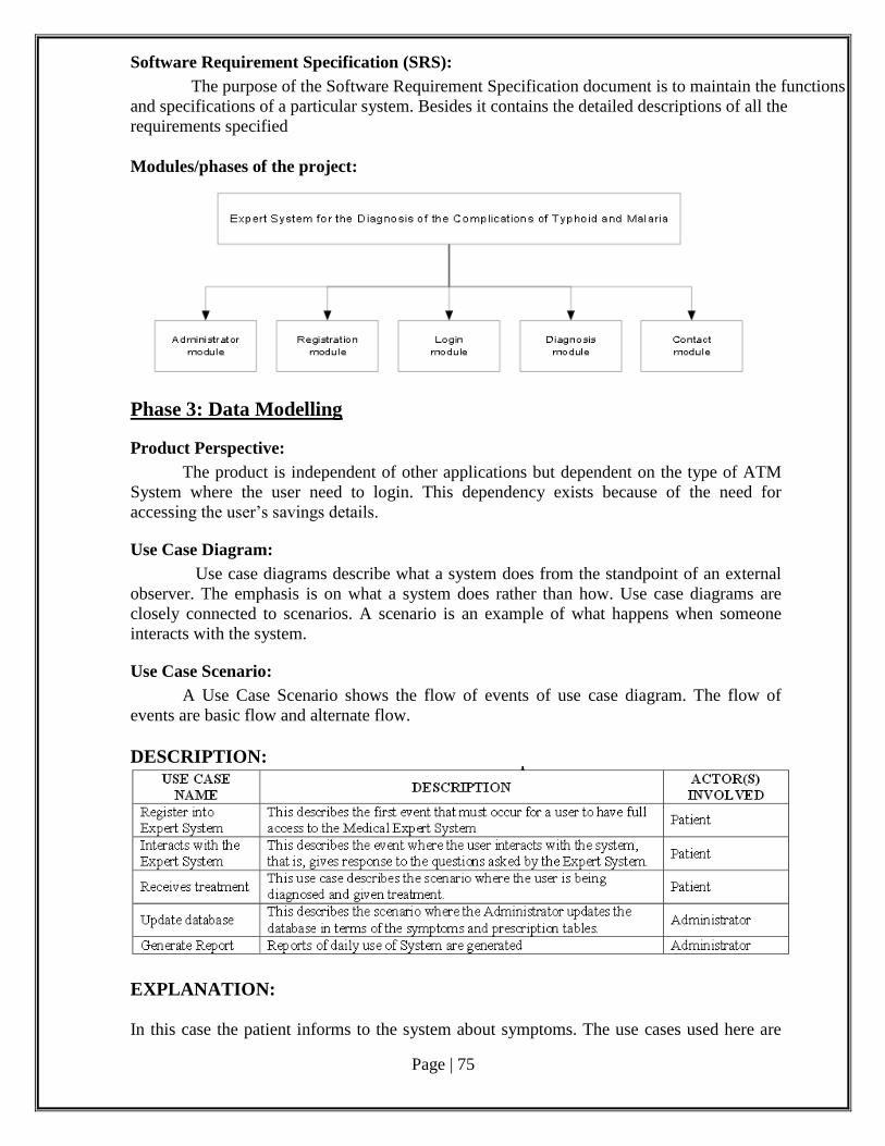
Page | 75
Software Requirement Specification (SRS):
The purpose of the Software Requirement Specification document is to maintain the functions
and specifications of a particular system. Besides it contains the detailed descriptions of all the
requirements specified
Modules/phases of the project:
Phase 3: Data Modelling
Product Perspective:
The product is independent of other applications but dependent on the type of ATM
System where the user need to login. This dependency exists because of the need for
accessing the user’s savings details.
Use Case Diagram:
Use case diagrams describe what a system does from the standpoint of an external
observer. The emphasis is on what a system does rather than how. Use case diagrams are
closely connected to scenarios. A scenario is an example of what happens when someone
interacts with the system.
Use Case Scenario:
A Use Case Scenario shows the flow of events of use case diagram. The flow of
events are basic flow and alternate flow.
DESCRIPTION:
EXPLANATION:
In this case the patient informs to the system about symptoms. The use cases used here are
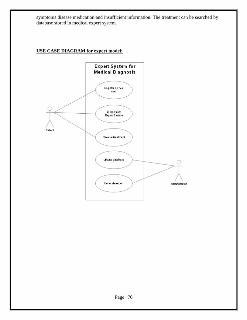
Page | 76
symptoms disease medication and insufficient information. The treatment can be searched by
database stored in medical expert system.
USE CASE DIAGRAM for expert model:
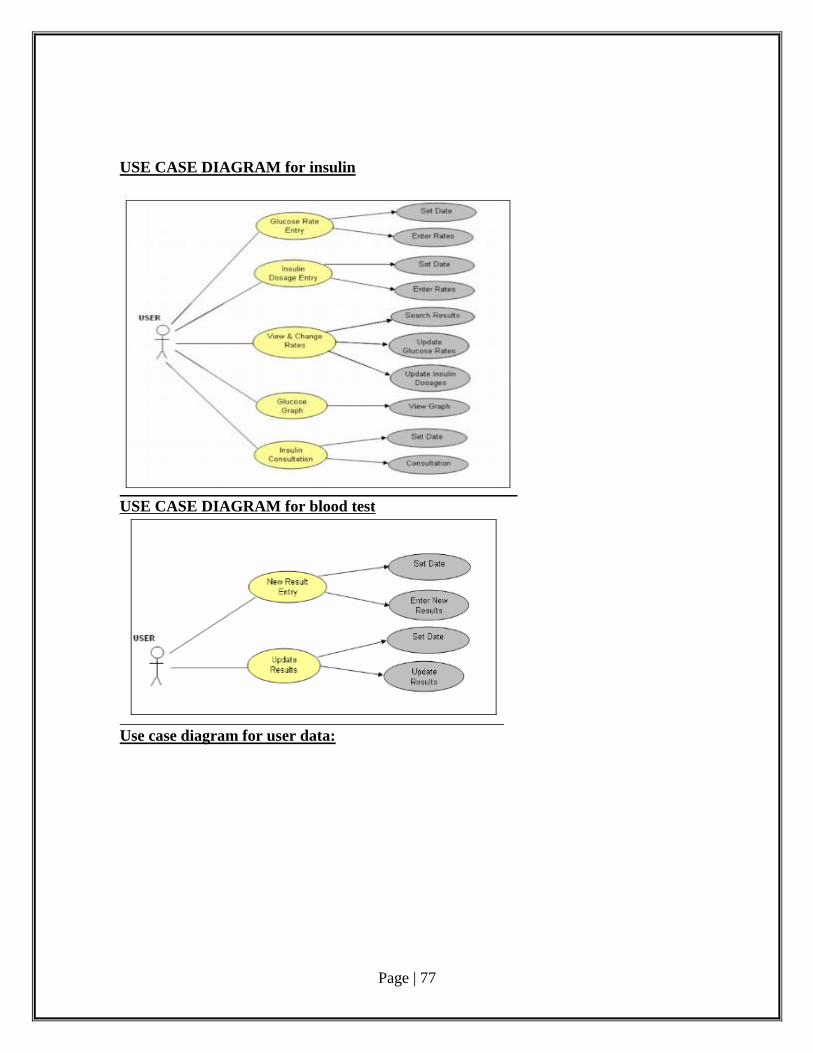
Page | 77
USE CASE DIAGRAM for insulin
USE CASE DIAGRAM for blood test
Use case diagram for user data:
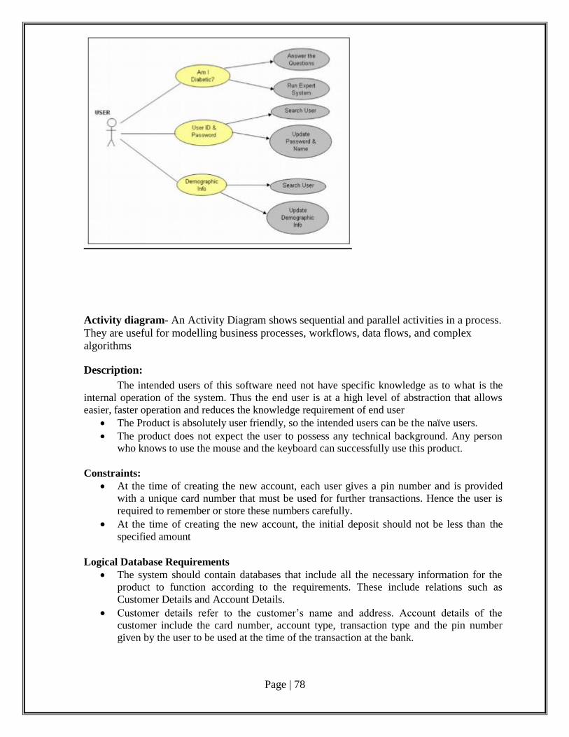
Page | 78
Activity diagram- An Activity Diagram shows sequential and parallel activities in a process.
They are useful for modelling business processes, workflows, data flows, and complex
algorithms
Description:
The intended users of this software need not have specific knowledge as to what is the
internal operation of the system. Thus the end user is at a high level of abstraction that allows
easier, faster operation and reduces the knowledge requirement of end user
The Product is absolutely user friendly, so the intended users can be the naïve users.
The product does not expect the user to possess any technical background. Any person
who knows to use the mouse and the keyboard can successfully use this product.
Constraints:
At the time of creating the new account, each user gives a pin number and is provided
with a unique card number that must be used for further transactions. Hence the user is
required to remember or store these numbers carefully.
At the time of creating the new account, the initial deposit should not be less than the
specified amount
Logical Database Requirements
The system should contain databases that include all the necessary information for the
product to function according to the requirements. These include relations such as
Customer Details and Account Details.
Customer details refer to the customer’s name and address. Account details of the
customer include the card number, account type, transaction type and the pin number
given by the user to be used at the time of the transaction at the bank.
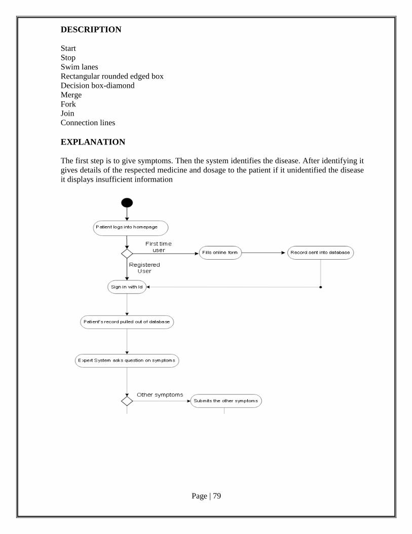
Page | 79
DESCRIPTION
Start
Stop
Swim lanes
Rectangular rounded edged box
Decision box-diamond
Merge
Fork
Join
Connection lines
EXPLANATION
The first step is to give symptoms. Then the system identifies the disease. After identifying it
gives details of the respected medicine and dosage to the patient if it unidentified the disease
it displays insufficient information
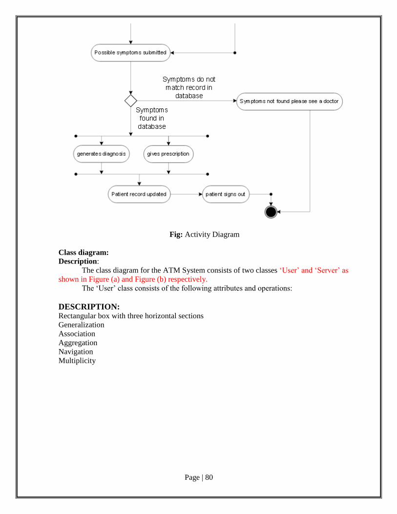
Page | 80
Fig: Activity Diagram
Class diagram:
Description:
The class diagram for the ATM System consists of two classes ‘User’ and ‘Server’ as
shown in Figure (a) and Figure (b) respectively.
The ‘User’ class consists of the following attributes and operations:
DESCRIPTION: Rectangular box with three horizontal sections
Generalization
Association
Aggregation
Navigation
Multiplicity
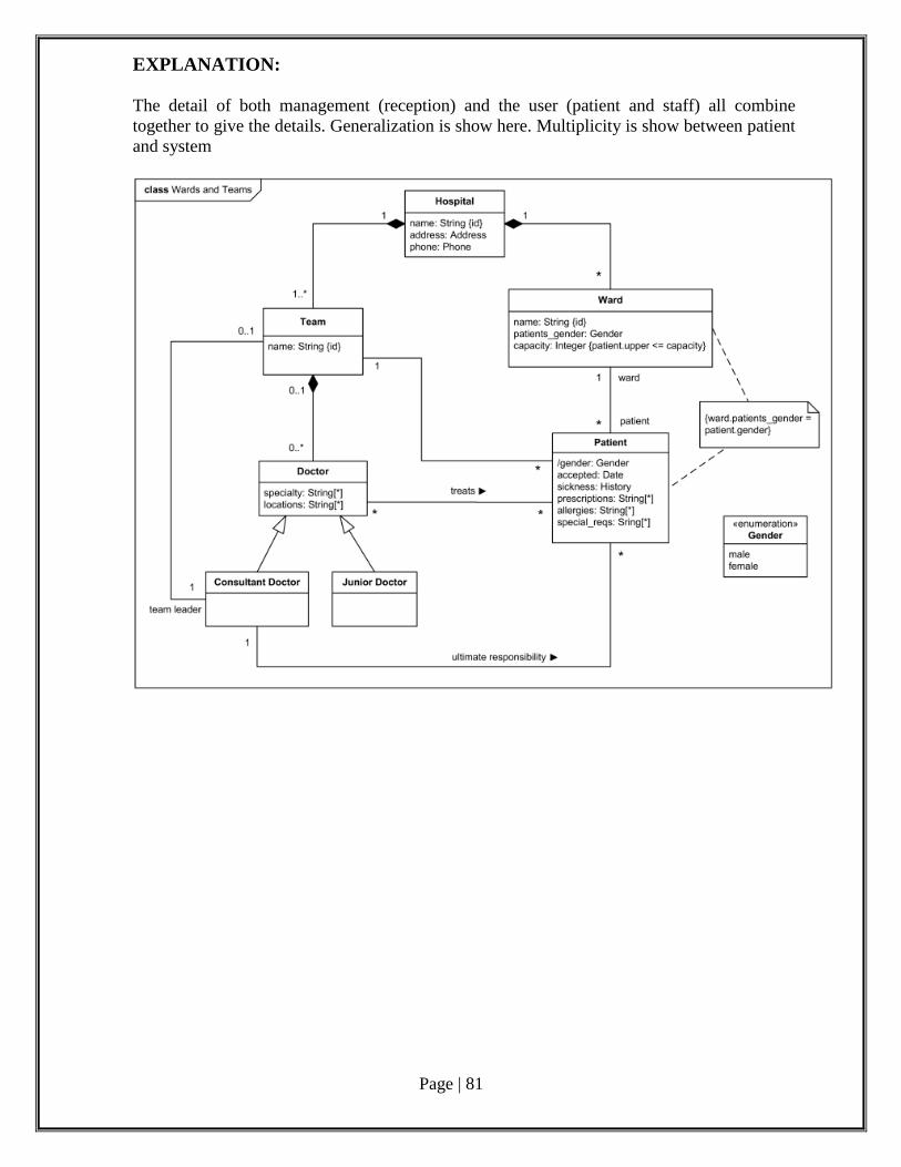
Page | 81
EXPLANATION:
The detail of both management (reception) and the user (patient and staff) all combine
together to give the details. Generalization is show here. Multiplicity is show between patient
and system
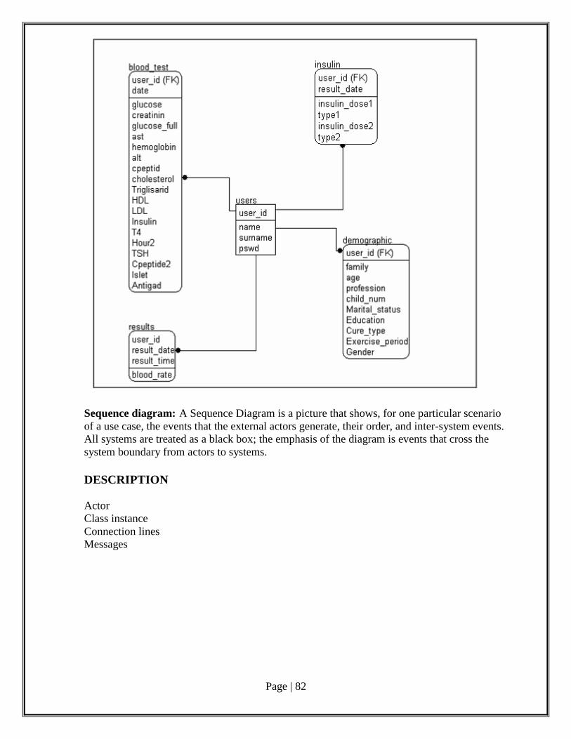
Page | 82
Sequence diagram: A Sequence Diagram is a picture that shows, for one particular scenario
of a use case, the events that the external actors generate, their order, and inter-system events.
All systems are treated as a black box; the emphasis of the diagram is events that cross the
system boundary from actors to systems.
DESCRIPTION
Actor
Class instance
Connection lines
Messages
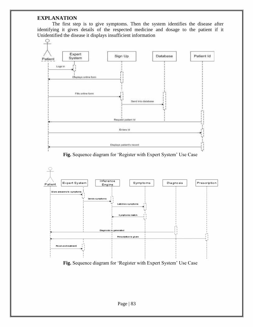
Page | 83
EXPLANATION The first step is to give symptoms. Then the system identifies the disease after
identifying it gives details of the respected medicine and dosage to the patient if it
Unidentified the disease it displays insufficient information
Fig. Sequence diagram for ‘Register with Expert System’ Use Case
Fig. Sequence diagram for ‘Register with Expert System’ Use Case

Page | 84
Fig. patient relationship
Page | 85
Phase 4: Software Development and Debugging
Code generation: The Code Generation generates the code for the process using some
programming languages like java, C++ etc.
Program:
1.LOGIN MODULE:
Private Sub Command1_Click()
If Text1.Text = "divya" And Text2.Text = "1234" Then
MsgBox "login sucessful"
Form2.Show
Else
MsgBox "invaild password or user name"
End If
End Sub
Private Sub Command2_Click()
End
End Sub
2.MAIN MENU MODULE:
Private Sub Command1_Click()
Form3.Show
End Sub
Private Sub Command2_Click()
Form4.Show
End Sub
Private Sub Command3_Click()
end
End Sub
3.PATIENT DETAILS:
Private Sub Command1_Click()
If Data1.Recordset.EOF <> True Then
Data1.Recordset.MoveLast
End If
Data1.Recordset.AddProposed
Data1.Recordset.Fields("patient name") = Text1.Text
Data1.Recordset.Fields("age") = Val(Text2.Text)
Data1.Recordset.Fields("sex") = Text3.Text
Data1.Recordset.Fields("symptoms") = Text4.Text
Data1.Recordset.Update
Form2.Show
Unload Me
End Sub
Page | 86
4. DOCTOR LOGIN MODULE
Private Sub Command1_Click()
If Text1.Text = "nandhini" And Text2.Text = "987654" Then
MsgBox "login sucessful"
Form2.Show
Else
MsgBox "invaild password or user name"
End If
End Sub
Private Sub Command2_Click()
End
End Sub
5. TREATMENT MODULE
Private Sub Command1_Click() Dim n As Long Dim a As String Data1.Recordset.MoveFirst a = text1.Text Do While Data1.Recordset.EOF <> True If Data1.Recordset.Fields("symptoms submitted") = a Then GoTo l1 Else Data1.Recordset.MoveNext End If Loop l1: Data1.Recordset.Edit MsgBox Data1.Recordset.Fields("disease") MsgBox Data1.Recordset.Fields("remedy") Form2.Show Unload Me End Sub
Phase 5: Software Testing Deployment: A Deployment Diagram shows the assignment of concrete software artefacts
to computational nodes. It shows the deployment of software elements to the physical
architecture and the communication between physical elements
DESCRIPTION: Cubes
Connection lines
EXPLANATION: The medical expert system software is installed in the hospital server which can be
accessed from anywhere. The external pc can just see the details and user performs all the
operation.
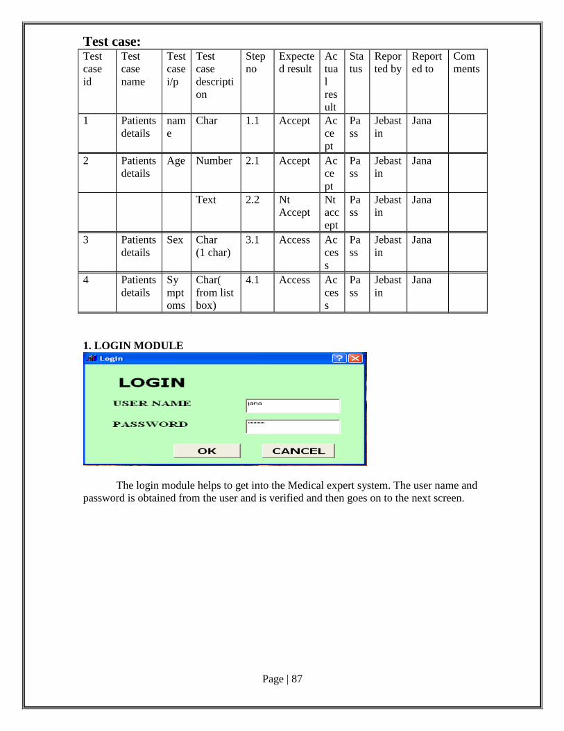
Page | 87
Test case: Test
case
id
Test
case
name
Test
case
i/p
Test
case
descripti
on
Step
no
Expecte
d result
Ac
tua
l
res
ult
Sta
tus
Repor
ted by
Report
ed to
Com
ments
1 Patients
details
nam
e
Char 1.1 Accept Ac
ce
pt
Pa
ss
Jebast
in
Jana
2 Patients
details
Age Number 2.1 Accept Ac
ce
pt
Pa
ss
Jebast
in
Jana
Text 2.2 Nt
Accept
Nt
acc
ept
Pa
ss
Jebast
in
Jana
3 Patients
details
Sex Char
(1 char)
3.1 Access Ac
ces
s
Pa
ss
Jebast
in
Jana
4 Patients
details
Sy
mpt
oms
Char(
from list
box)
4.1 Access Ac
ces
s
Pa
ss
Jebast
in
Jana
1. LOGIN MODULE
The login module helps to get into the Medical expert system. The user name and
password is obtained from the user and is verified and then goes on to the next screen.
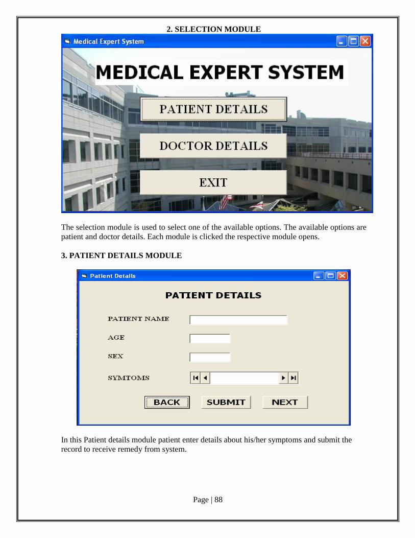
Page | 88
2. SELECTION MODULE
The selection module is used to select one of the available options. The available options are
patient and doctor details. Each module is clicked the respective module opens.
3. PATIENT DETAILS MODULE
In this Patient details module patient enter details about his/her symptoms and submit the
record to receive remedy from system.
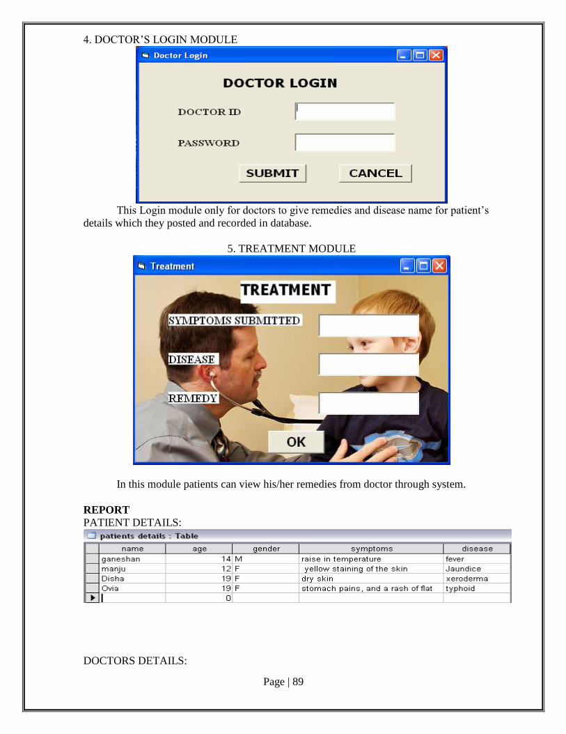
Page | 89
4. DOCTOR’S LOGIN MODULE
This Login module only for doctors to give remedies and disease name for patient’s
details which they posted and recorded in database.
5. TREATMENT MODULE
In this module patients can view his/her remedies from doctor through system.
REPORT PATIENT DETAILS:
DOCTORS DETAILS:
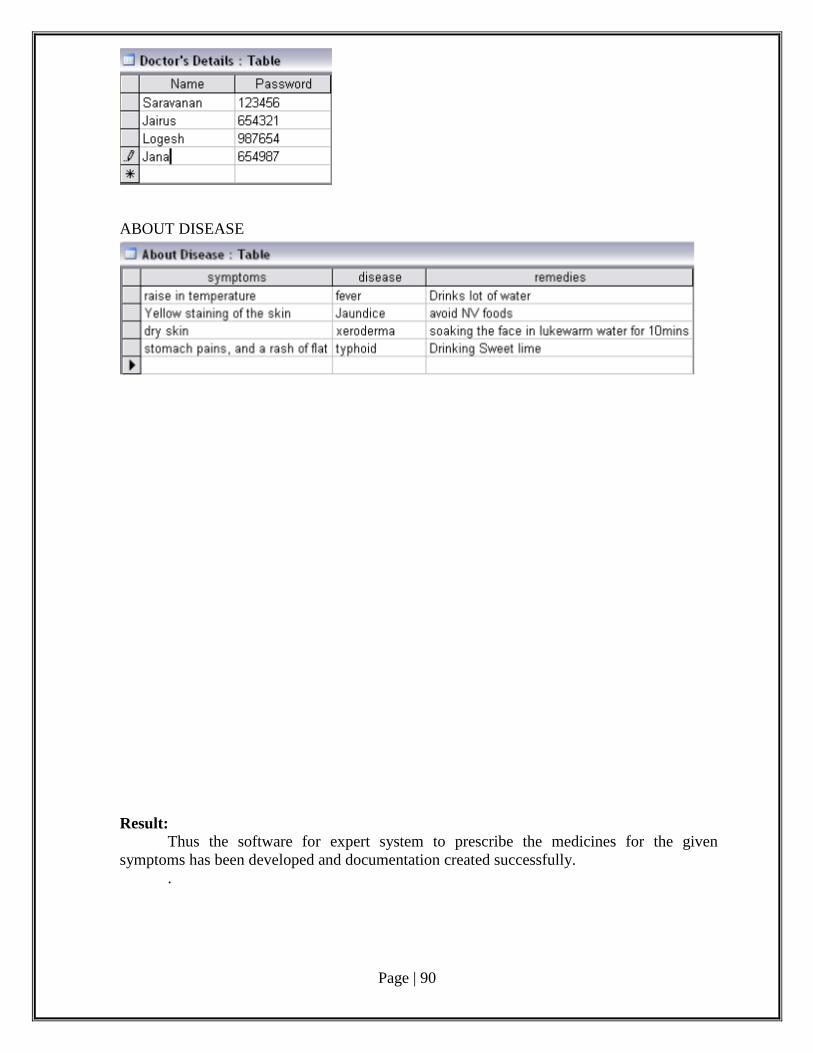
Page | 90
ABOUT DISEASE
Result:
Thus the software for expert system to prescribe the medicines for the given
symptoms has been developed and documentation created successfully.
.
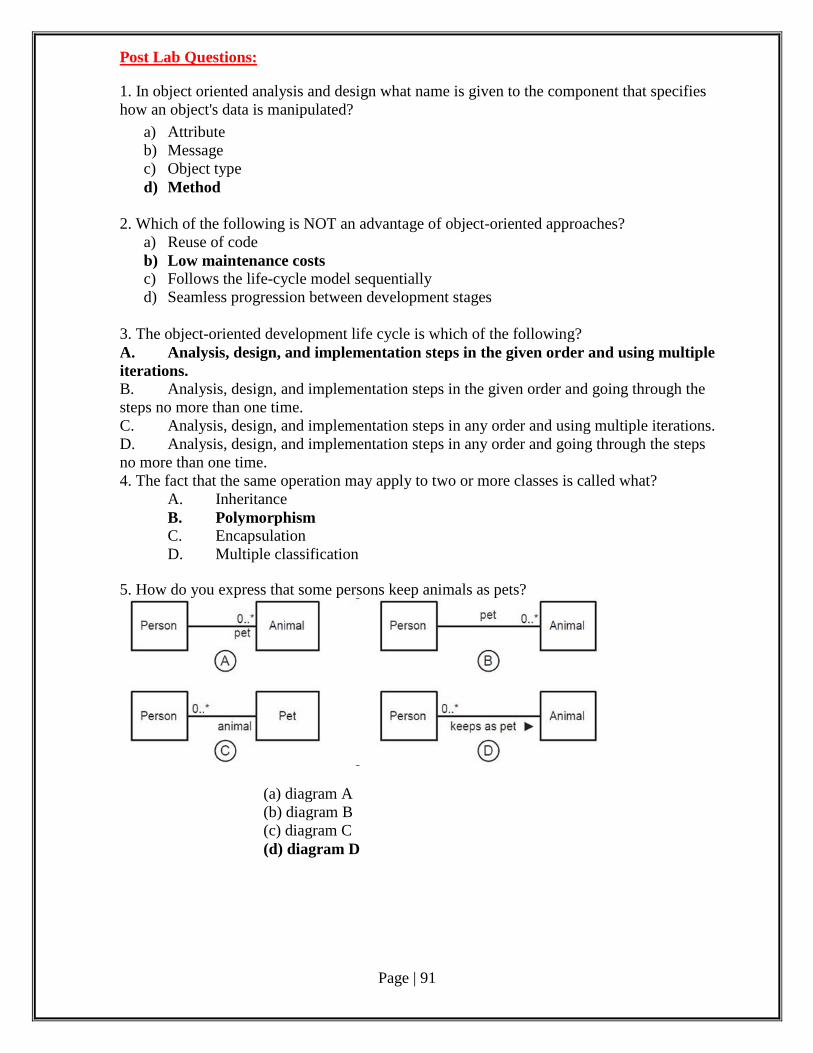
Page | 91
Post Lab Questions:
1. In object oriented analysis and design what name is given to the component that specifies
how an object's data is manipulated?
a) Attribute
b) Message
c) Object type
d) Method
2. Which of the following is NOT an advantage of object-oriented approaches?
a) Reuse of code
b) Low maintenance costs
c) Follows the life-cycle model sequentially
d) Seamless progression between development stages
3. The object-oriented development life cycle is which of the following?
A. Analysis, design, and implementation steps in the given order and using multiple
iterations.
B. Analysis, design, and implementation steps in the given order and going through the
steps no more than one time.
C. Analysis, design, and implementation steps in any order and using multiple iterations.
D. Analysis, design, and implementation steps in any order and going through the steps
no more than one time.
4. The fact that the same operation may apply to two or more classes is called what?
A. Inheritance
B. Polymorphism
C. Encapsulation
D. Multiple classification
5. How do you express that some persons keep animals as pets?
(a) diagram A
(b) diagram B
(c) diagram C
(d) diagram D
Page | 92
Ex.No : 7 Remote computer monitoring Date :
AIM:
To develop software for remote computer monitoring system with documentation.
Pre Lab Questions:
1.The aim of software engineering is to produce software that is (a) Fault-free (b) Delivered on time (c) Delivered within budget (d) Satisfies users' needs (e) All of these are the aims of software engineering.
2.Prototyping is appropriate for
(a) Data-oriented applications
(b) Applications with emphasis on the user interface
(c) Applications which are highly interactive
(d) Development teams who lack domain experience
(e) All of the above.
3.What are the factors to be considered when planning a software development effort?
(a) Performance, Problem, Product, Planning
(b) People, Problem, Product, Process
(c) People, Problem, Productivity, Performance
(d) People, Problem, Product, Portability
(e) Productivity, Programming, Performance, Pay-Off.
4.Which of the following could be a deliverable for a software system?
(a) Source Code
(b) Reference Manual
(c) Requirements Document
(d) User's Guide
(e) All of the above.
5.Software configuration activities would not include
(a) Identify change
(b) Control change
(c) Ensure improper implementation of change
(d) Report change to interested parties
(e) All of the above.
Page | 93
Phase 1: Problem Analysis and Project Planning
i. Thorough study of the problem:
Traditional Methodologies
The existing system is used to edit the form, update the patient details of the hospital
management system. The retrieving of required data of the patients, staff details, fees,
Expense, drug, admission, income.
Problem Definition:
The main idea of problem analysis is collecting data on the existing system and
performing critical documentation of data and its related information.
The Problem Analysis is conducted with following objectives,
To maintain the patient details of the hospital.
To maintain the details of the staff members.
Retrieving the resulted data.
ii.Identify Project scope, Objectives and Infrastructure
The Project Hospital Management is done to computerize the hospital details and to
maintain it focus on higher availability. By using this project we can be able to retrieve all
the details of the patient and staff members.
In this project we have used MS Visual Basic6.0 as the programming language
because it enhances the user friendliness and provides an improved presentation on the front
end. The database has been selected as MS Access due to its capability of handling large
volumes of data spread across several database and users.
HARDWARE REQUIREMENTS:
CPU : HP PROCESSOR SPEED: 2.80GHz/1066MHz
MEMORY : 2GB RAM
HARD DISK : 250GB
MONITOR : HP 18.5’
SOFTWARE REQUIREMENTS:
Operating systems: Microsoft Windows XP
Packages: MS Visual Basic 6.0, MS Access 2003
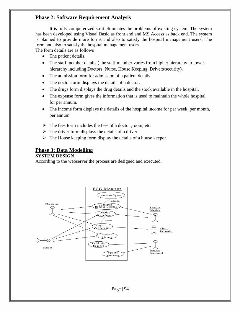
Page | 94
Phase 2: Software Requirement Analysis
It is fully computerized so it eliminates the problems of existing system. The system
has been developed using Visual Basic as front end and MS Access as back end. The system
is planned to provide more forms and also to satisfy the hospital management users. The
form and also to satisfy the hospital management users.
The form details are as follows
The patient details.
The staff member details ( the staff member varies from higher hierarchy to lower
hierarchy including Doctors, Nurse, House Keeping, Drivers/security).
The admission form for admission of a patient details.
The doctor form displays the details of a doctor.
The drugs form displays the drug details and the stock available in the hospital.
The expense form gives the information that is used to maintain the whole hospital
for per annum.
The income form displays the details of the hospital income for per week, per month,
per annum.
The fees form includes the fees of a doctor ,room, etc.
The driver form displays the details of a driver.
The House keeping form display the details of a house keeper.
Phase 3: Data Modelling SYSTEM DESIGN According to the webserver the process are designed and executed.
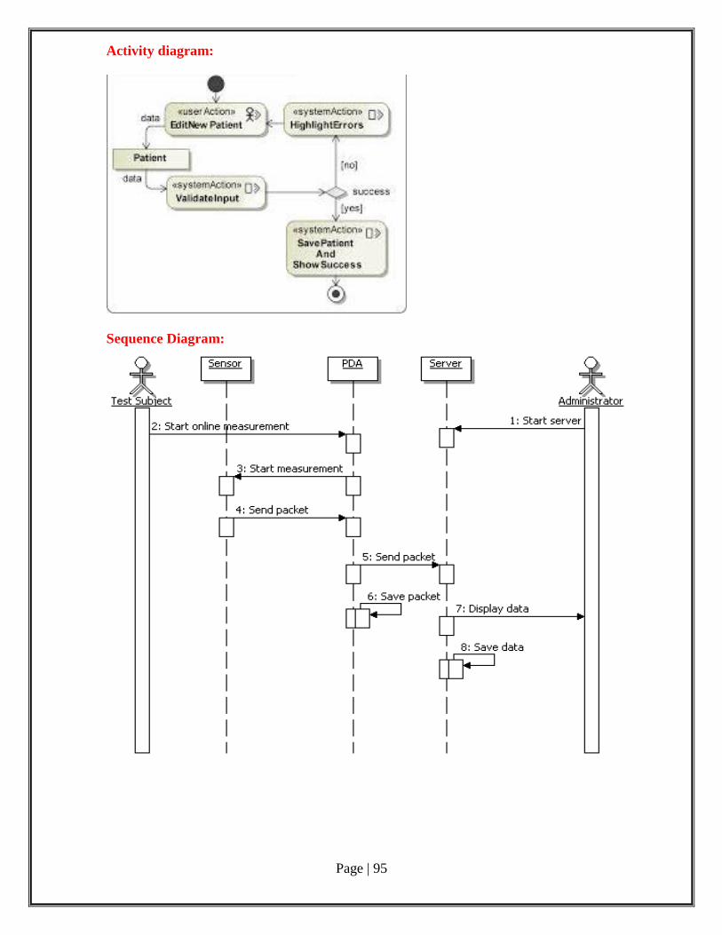
Page | 95
Activity diagram:
Sequence Diagram:
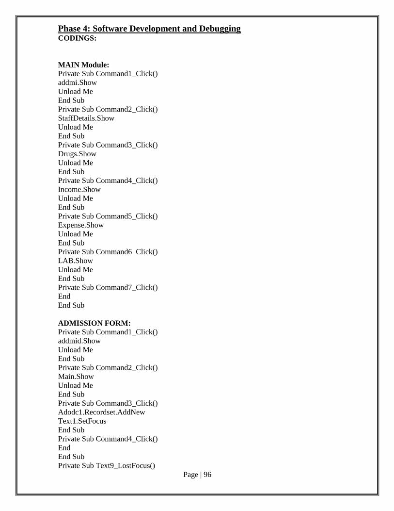
Page | 96
Phase 4: Software Development and Debugging CODINGS:
MAIN Module: Private Sub Command1_Click()
addmi.Show
Unload Me
End Sub
Private Sub Command2_Click()
StaffDetails.Show
Unload Me
End Sub
Private Sub Command3_Click()
Drugs.Show
Unload Me
End Sub
Private Sub Command4_Click()
Income.Show
Unload Me
End Sub
Private Sub Command5_Click()
Expense.Show
Unload Me
End Sub
Private Sub Command6_Click()
LAB.Show
Unload Me
End Sub
Private Sub Command7_Click()
End
End Sub
ADMISSION FORM: Private Sub Command1_Click()
addmid.Show
Unload Me
End Sub
Private Sub Command2_Click()
Main.Show
Unload Me
End Sub
Private Sub Command3_Click()
Adodc1.Recordset.AddNew
Text1.SetFocus
End Sub
Private Sub Command4_Click()
End
End Sub
Private Sub Text9_LostFocus()
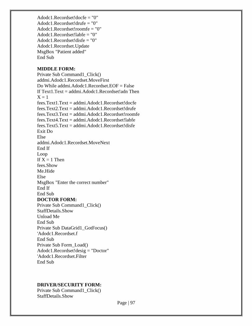
Page | 97
Adodc1.Recordset!docfe = "0"
Adodc1.Recordset!drufe = "0"
Adodc1.Recordset!roomfe = "0"
Adodc1.Recordset!labfe = "0"
Adodc1.Recordset!disfe = "0"
Adodc1.Recordset.Update
MsgBox "Patient added"
End Sub
MIDDLE FORM: Private Sub Command1_Click()
addmi.Adodc1.Recordset.MoveFirst
Do While addmi.Adodc1.Recordset.EOF = False
If Text1.Text = addmi.Adodc1.Recordset!adn Then
X = 1
fees.Text1.Text = addmi.Adodc1.Recordset!docfe
fees.Text2.Text = addmi.Adodc1.Recordset!drufe
fees.Text3.Text = addmi.Adodc1.Recordset!roomfe
fees.Text4.Text = addmi.Adodc1.Recordset!labfe
fees.Text5.Text = addmi.Adodc1.Recordset!disfe
Exit Do
Else
addmi.Adodc1.Recordset.MoveNext
End If
Loop
If X = 1 Then
fees.Show
Me.Hide
Else
MsgBox "Enter the correct number"
End If
End Sub
DOCTOR FORM: Private Sub Command1_Click()
StaffDetails.Show
Unload Me
End Sub
Private Sub DataGrid1_GotFocus()
'Adodc1.Recordset.f
End Sub
Private Sub Form_Load()
Adodc1.Recordset!desig = "Doctor"
'Adodc1.Recordset.Filter
End Sub
DRIVER/SECURITY FORM: Private Sub Command1_Click()
StaffDetails.Show
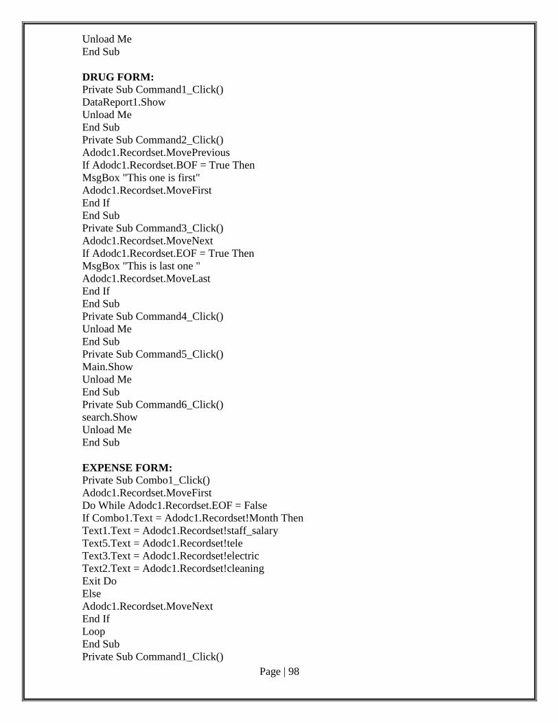
Page | 98
Unload Me
End Sub
DRUG FORM: Private Sub Command1_Click()
DataReport1.Show
Unload Me
End Sub
Private Sub Command2_Click()
Adodc1.Recordset.MovePrevious
If Adodc1.Recordset.BOF = True Then
MsgBox "This one is first"
Adodc1.Recordset.MoveFirst
End If
End Sub
Private Sub Command3_Click()
Adodc1.Recordset.MoveNext
If Adodc1.Recordset.EOF = True Then
MsgBox "This is last one "
Adodc1.Recordset.MoveLast
End If
End Sub
Private Sub Command4_Click()
Unload Me
End Sub
Private Sub Command5_Click()
Main.Show
Unload Me
End Sub
Private Sub Command6_Click()
search.Show
Unload Me
End Sub
EXPENSE FORM: Private Sub Combo1_Click()
Adodc1.Recordset.MoveFirst
Do While Adodc1.Recordset.EOF = False
If Combo1.Text = Adodc1.Recordset!Month Then
Text1.Text = Adodc1.Recordset!staff_salary
Text5.Text = Adodc1.Recordset!tele
Text3.Text = Adodc1.Recordset!electric
Text2.Text = Adodc1.Recordset!cleaning
Exit Do
Else
Adodc1.Recordset.MoveNext
End If
Loop
End Sub
Private Sub Command1_Click()
Page | 99
Expense1.Show
Unload Me
End Sub
Private Sub Command2_Click()
Main.Show
Unload Me
End Sub
Private Sub Command3_Click()
Unload Me
End Sub
Private Sub Form_Load()
While Adodc1.Recordset.EOF = False
Combo1.AddItem Adodc1.Recordset!Month
Adodc1.Recordset.MoveNext
Wend
End Sub
ANNUAL EXPENSE FORM: Dim X As Long
Private Sub Command1_Click()
Unload Me
End Sub
Private Sub Command2_Click()
Expense.Show
Unload Me
End Sub
Private Sub Form_Load()
X = 0
Expense.Adodc1.Recordset.MoveFirst
Do While Expense.Adodc1.Recordset.EOF = False
X = Val(X) + Val(Expense.Adodc1.Recordset!staff_salary) +
Val(Expense.Adodc1.Recordset!tele) + Val(Expense.Adodc1.Recordset!electric) +
Val(Expense.Adodc1.Recordset!cleaning)
Expense.Adodc1.Recordset.MoveNext
Loop
Label1.Caption = Val(X)
End Sub
FEES DETAILS FORM: Private Sub Command2_Click()
addmi.Show
Unload Me
End Sub
Private Sub Command3_Click()
End
End Sub
Private Sub Command4_Click()
addmi.Adodc1.Recordset!docfe = fees.Text1.Text
addmi.Adodc1.Recordset!drufe = fees.Text2.Text
addmi.Adodc1.Recordset!roomfe = fees.Text3.Text
addmi.Adodc1.Recordset!labfe = fees.Text4.Text
Page | 100
addmi.Adodc1.Recordset!disfe = fees.Text5.Text
addmi.Adodc1.Recordset.Update
MsgBox "fees updated"
End Sub
Private Sub Form_MouseMove(Button As Integer, Shift As Integer, X As Single, Y As
Single)
Text6.Text = (Val(Text1.Text) + Val(Text2.Text) + Val(Text3.Text) + Val(Text4.Text))
Label8.Caption = addmi.Adodc1.Recordset!Name
End Sub
Private Sub Text5_LostFocus()
Text6.Text = (Val(Text1.Text) + Val(Text2.Text) + Val(Text3.Text) + Val(Text4.Text))
End Sub
HOUSE KEEPING FORM: Private Sub Command1_Click()
StaffDetails.Show
Unload Me
End Sub
INCOME FORM: Private Sub Command1_Click()
Main.Show
Unload Me
End Sub
Private Sub Form_Load()
addmi.Adodc1.Recordset.MoveFirst
Do While addmi.Adodc1.Recordset.EOF = False
a = a + Val(addmi.Adodc1.Recordset!docfe) + Val(addmi.Adodc1.Recordset!drufe) +
Val(addmi.Adodc1.Recordset!roomfe) + Val(addmi.Adodc1.Recordset!labfe)
addmi.Adodc1.Recordset.MoveNext
Loop
Label7.Caption = a
End Sub
Private Sub Label1_Click()
Income.Show
Unload Me
End Sub
LAB DETAIL FORM: Private Sub Command6_Click()
End
End Sub
Private Sub Command7_Click()
Main.Show
Unload Me
End Sub
Private Sub Form_Load()
Adodc1.Recordset.MoveFirst
Do While Adodc1.Recordset.EOF = False
b = b + Val(Adodc1.Recordset!blood)
Page | 101
Adodc1.Recordset.MoveNext
Loop
Label2.Caption = b
Adodc1.Recordset.MoveFirst
Do While Adodc1.Recordset.EOF = False
c = c + Val(Adodc1.Recordset!sugar)
Adodc1.Recordset.MoveNext
Loop
Label3.Caption = c
Adodc1.Recordset.MoveFirst
Do While Adodc1.Recordset.EOF = False
d = d + Val(Adodc1.Recordset!malaria)
Adodc1.Recordset.MoveNext
Loop
Label4.Caption = d
Adodc1.Recordset.MoveFirst
Do While Adodc1.Recordset.EOF = False
e = e + Val(Adodc1.Recordset!typoid)
Adodc1.Recordset.MoveNext
Loop
Label5.Caption = e
Label6.Caption = Val(Label2.Caption) + Val(Label3.Caption) + Val(Label4.Caption) +
Val(Label5.Caption)
End Sub
NURSE FORM: Private Sub Command1_Click()
StaffDetails.Show
Unload Me
End Sub
STAFF DETAIL FORM: Private Sub Command1_Click()
Doctors.Show
Unload Me
End Sub
Private Sub Command2_Click()
Nurse.Show
Unload Me
End Sub
Private Sub Command3_Click()
HouseKeeping.Show
Unload Me
End Sub
Private Sub Command4_Click()
Drivers.Show
Unload Me
End Sub
Private Sub Command5_Click()
Main.Show
Page | 102
Unload Me
End Sub
Phase 5: Software Testing
There are two types of software testing
1. Code testing.
2. Specification Testing .
The philosophy of testing is to mind the errors. Test cares are designed. A Test is a
set of data that system will process at normal input.
UNIT TESTING:
The form that made up of system are tested in unit testing
Unit testing is preformed from bottom up starting with the smallest and lowest level
models and processed one at time
The bottom level modules are tested and the next level in the lower one are tested
SYSTEM TESTING:
System tested is done to find the description between the system and its original
objective, current specification and system documentation.
INTEGRATION TESTING:
Integration testing is a systematic testing the construction of the form structure while
at same time conducting test to remove errors associated within the interface.
Asking the users about the form required by then test the output generated are all
displayed by system under consideration.
Output testing has not resulted in many corrections in the systems.
Conclusion :
Hospital management has vast amount of data to manipulate. Manual access and
storing of data takes long time for processing. Also there is chance of data loss. The online
hospital management encloses all the information required in a single kit. Hence it gains
advantage in time basis and accuracy basis. Locating data is made easy here.

Page | 103
Result:
Thus the remote computer monitoring system was successfully analyzed, designed,
implemented, verified and tested successfully.
Page | 104
Post Lab Questions:
1. What threatens the quality and timeliness of the software to be produced?
a) Known risks
b) Business risks
c) Project risks
d) Technical risks
2. Which of the following is not a business risk?
a) building an excellent product or system that no one really wants
b) losing the support of senior management due to a change in focus or change in
people
c) lack of documented requirements or software scope
d) losing budgetary or personnel commitment
3. Which of the following term is best defined by the statement:” the degree of uncertainty
that the product will meet its requirements and be fit for its intended use.”?
a) Performance risk
b) Cost risk
c) Support risk
d) Schedule risk
4. Which of the following is/are White box technique?
a) Statement Testing
b) Decision Testing
c) Condition Coverage
d) All of these
5. Which of the following term describes testing?
a) Finding broken code
b) Evaluating deliverable to find errors
c) A stage of all projects
d) None of the mentioned
Page | 105
Ex.No:8 ATM System
Date:
AIM:
To develop software for ATM system with documentation.
Pre-Lab Questions:
1. One of the fault base testing techniques is
(A) unit testing. (B) beta testing.
(C) Stress testing. (D) mutation testing.
2. If every requirement stated in the Software Requirement Specification (SRS) has
only one interpretation, SRS is said to be
(A) correct. (B) unambiguous.
(C) consistent. (D) verifiable.
3. SRS is also known as specification of
(A) White box testing (B) Stress testing
(C) Integrated testing (D) Black box testing
4. A COCOMO model is
(A) Common Cost Estimation Model.
(B) Constructive Cost Estimation Model.
(C) Complete Cost Estimation Model.
(D) Comprehensive Cost Estimation Model.
5. In the spiral model ‘risk analysis’ is performed
(A) In the first loop (B) in the first and second loop
(C) In every loop (D) before using spiral model
Phase 1: Problem Analysis and Project Planning Problem Statement:
A Problem Statement lists out the problems faced by the process before the
development of the System.
i. Thorough study of the problem:
Banking is one of the common and day to day attribute of life. Nowadays it is totally
different from that existed a few years ago banking has become completely computerized
new facilities such as credit cards, debit cards & ATM has been introduced. ATM is
automatic teller machine which is basically used to withdraw money from an account.
ATM is another type of banking where the most frequently type of transaction made
is withdrawal. A user may withdraw as much as many amount as he wants until his account
holds a sum greater than his withdrawal amount. ATM is completely automated and there is
Page | 106
no necessity of the ATM center being placed at the bank itself. It can be placed in the
shopping malls, airports, railway stations etc.
This ATM system can use any kind of interface. But it should be user friendly and not
confusing. Help manuals should be provided in case any customer has problem working with
the software.
The system will retain information on the entire customer who has necessity rights to
access the service. It will contain the balance amount in the account, rate of interest, any
special allowance for that customer and most of all pin number of the customer. The ATM
system should be compatible with any kind of database such as MS-ACCESS, DB2,
ORACLE, SQL, SERVER etc. the emphasis here is on consistency.
Some customer could have availed some special offers on his ATM cards. So this
must be taken care of and the appropriate data should be dealt with.
The ATM should provide easy access to the data for the customer. It should also have a
highly secure interface so that one can take money one behalf of others. So the security is one
of the main aspects in ATM.
ii.Identify Project scope, Objectives and Infrastructure
The objective of this software is similar to ATM software installed in ATM center. It should first
validate the pin in the ATM card. Then the type of transaction is enquired and the information from the
customer is validated. If it is a withdrawal the amount is asked. After the money is delivered the
transaction just made is updated in the database where the customer’s information is stored.
The scope of the project is to design an ATM system that will help in completely automatic banking this
software is going to be designed for withdrawal and deposit of money and register the transaction in the
database where the customer’s information is stored.
Hard disk: The database connectivity requires a hardware configuration that is on-line. This
makes it necessary to have a fast database system (such as any RDBMS) running on high
rpm hard-disk permitting complete data redundancy and backup systems to support the
primary goal of reliability.
The system must interface with the standard output device, keyboard and mouse to interact
with this software.
Software interfaces: Back End: MS Access 2007
Front End: Microsoft Visual Basic 6.0
Operating Environment:
The system works in Windows XP or higher versions.
ArgoUML Tool
The main purpose of the Software Requirement Analysis is to maintain all functions
and specifications of an ATM System.

Page | 107
Phase 2: Software Requirement Analysis
Software Requirement Specification (SRS):
The purpose of the Software Requirement Specification document is to maintain the functions
and specifications of a particular system. Besides it contains the detailed descriptions of all the
requirements specified
Modules/phases of the project:
To develop an ATM system to perform the following functions:
The customer logs into the system using card number and pin number. The
system checks for validation.
The system queries the customer for the type of account either fixed deposit or
credit account. After getting the type of account the system shows the balance
left.
The system queries the customer for the transaction type either withdrawal or
deposit and the required amount. The user enters the amount and the
transaction if carries out.
The intended audience is any person who wants
To create account.
To withdraw or deposit either in fixed deposit or credit account
Allow a new user to create an account, either fixed or credit account by
entering the details and by depositing an initial amount.
Allow the existing user to enter his account details like card number, pin
number and account type to view his balance.
Allow the existing user to deposit an amount by entering the amount to be
deposited after the balance had been viewed.
Allow the existing user to withdraw an amount by entering the amount to be
withdrawn after the balance had been viewed.
The primary benefits expected of the system are: user friendly, continuous
connectivity without failure, fault tolerant and involves lesser manpower
Phase 3: Data Modelling
Product Perspective:
The product is independent of other applications but dependent on the type of ATM
System where the user need to login. This dependency exists because of the need for
accessing the user’s savings details.
Product Functionality:
Signing up and becoming an authenticated User: The user has to give some
personal details to sign up and to become an authenticated user in order to use the
system
Login to the system: Login to the system using his/her Login ID and Password
date. The Server then validates the Login ID and Password and allows the user
access the system.
Check Availability of the money: User could check the availability of the money
and then go for withdrawal or deposit.
Page | 108
Selection of account type: Based on the user need chooses the desired
withdrawal or deposit option.
Transaction: After selecting a particular option the user needs to transfer or
deposit or withdraw the needed amount.
View account status: After transaction, the account details are displayed to the
user through a bill.
USE CASE DIAGRAM:
Use case diagrams describe what a system does from the standpoint of an external
observer. The emphasis is on what a system does rather than how. Use case diagrams are
closely connected to scenarios. A scenario is an example of what happens when someone
interacts with the system.
Use Case Scenario:
A Use Case Scenario shows the flow of events of use case diagram. The flow of
events are basic flow and alternate flow.
Identifying use-cases and actors: Creating a New Account
The user should provide his personal details to facilitate the bank clerk to create a new
account.
Identified use cases
i. Login:
Here the user enters the card and the inputs his password to enter into the main form.
If the password is incorrect, the system will display an error message.
ii. Transaction:
This is the important part of the ATM system, where there are two types of
transaction-withdrawal and deposit. While withdrawing the user specifies the amount and
may request for the printed output also.
iii. Maintaining Customer Information:
Here the administrator plays an important role, whose work is to add customer, delete
customer account, update customer account, etc.
Identified Actors
i Administrator:
Administrator plays an important role. He is the system designer. All the updating
works is done by him only like adding, deleting customer accounts.
ii Database:
All the transaction works-withdrawal and deposit are updated in the database.
iii Customer:
He is the external user the ATM system for taking money and depositing money also.
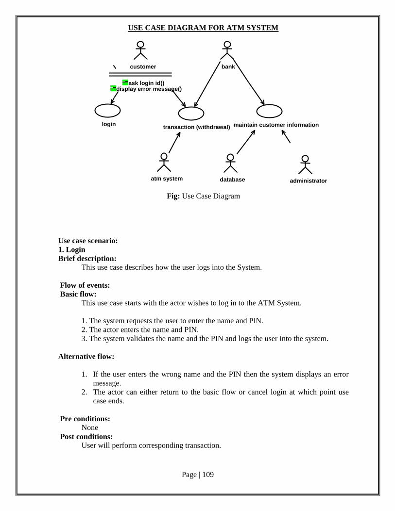
Page | 109
USE CASE DIAGRAM FOR ATM SYSTEM
Fig: Use Case Diagram
Use case scenario:
1. Login
Brief description:
This use case describes how the user logs into the System.
Flow of events:
Basic flow:
This use case starts with the actor wishes to log in to the ATM System.
1. The system requests the user to enter the name and PIN.
2. The actor enters the name and PIN.
3. The system validates the name and the PIN and logs the user into the system.
Alternative flow:
1. If the user enters the wrong name and the PIN then the system displays an error
message.
2. The actor can either return to the basic flow or cancel login at which point use
case ends.
Pre conditions:
None
Post conditions:
User will perform corresponding transaction.
login
customer
ask login id() display error message()
atm system
transaction (withdrawal)
bank
database
maintain customer information
administrator
Page | 110
2. Transaction
Brief description:
This describes the transaction that the user is doing.
Flow of events:
Basic flow:
This use case starts after the user has logged on to the system.
1. The system requests the user to enter the type of transaction of either withdrawal
or deposit and asks for customer information.
2. The actor enters the type of transaction and the customer information.
3. The system displays the corresponding transaction screen.
Alternative flow:
If the customer enters any wrong information then the system displays an error
message.
Pre Condition:
The user logs on to the system.
Post Condition:
Based on the transaction he gets the transaction screen.
3. Maintain Information about Customer
Brief description:
This describes how administrator takes care of customer information.
Flow of events:
Basic flow:
This use case starts after the administrator has logged into the system.
1. The system asks the administrator whether he wants to add or delete customer
information.
2. The administrator then enters the type of maintenance.
Alternative flow:
None
Pre Condition:
The administrator logs on to the system before this use case begin.
Post Condition:
Administrator gets the corresponding maintenance screen according to his choice.
Adding Customer
Basic flow:
1. This use case starts when the administrator has chosen to add customer’s
information.
2. The system asks the administrator to enter customer information.
3. The administrator enters the customer information.
4. The system displays the updated information.
Alternative flow:
If the administrator enters any wrong information the system displays an error
message.
Page | 111
Deleting Customer
Basic flow:
1. This use case starts when the administrator has chosen to delete an existing
customer from the system.
2. The system asks the administrator to enter the customer information.
3. Administrator enters the corresponding user information.
4. The system then displays updated results.
Alternative flow:
If the administrator has entered any wrong information then the system displays
administrator error message.
Updating an existing Customer account
Basic flow:
1. This use case starts when the administrator has chosen to update the customer’s
information.
2. The system asks the administrator to enter the customer information.
3. The administrator enters the customer information.
4. The system displays the updated information.
Alternative flow:
If the administrator has entered any wrong information then the system displays
administrator error message.
Activity diagram- An Activity Diagram shows sequential and parallel activities in a process.
They are useful for modelling business processes, workflows, data flows, and complex
algorithms
Description:
The intended users of this software need not have specific knowledge as to what is
the internal operation of the system. Thus the end user is at a high level of abstraction that
allows easier, faster operation and reduces the knowledge requirement of end user
The Product is absolutely user friendly, so the intended users can be the naïve users.
The product does not expect the user to possess any technical background. Any
person who knows to use the mouse and the keyboard can successfully use this
product.
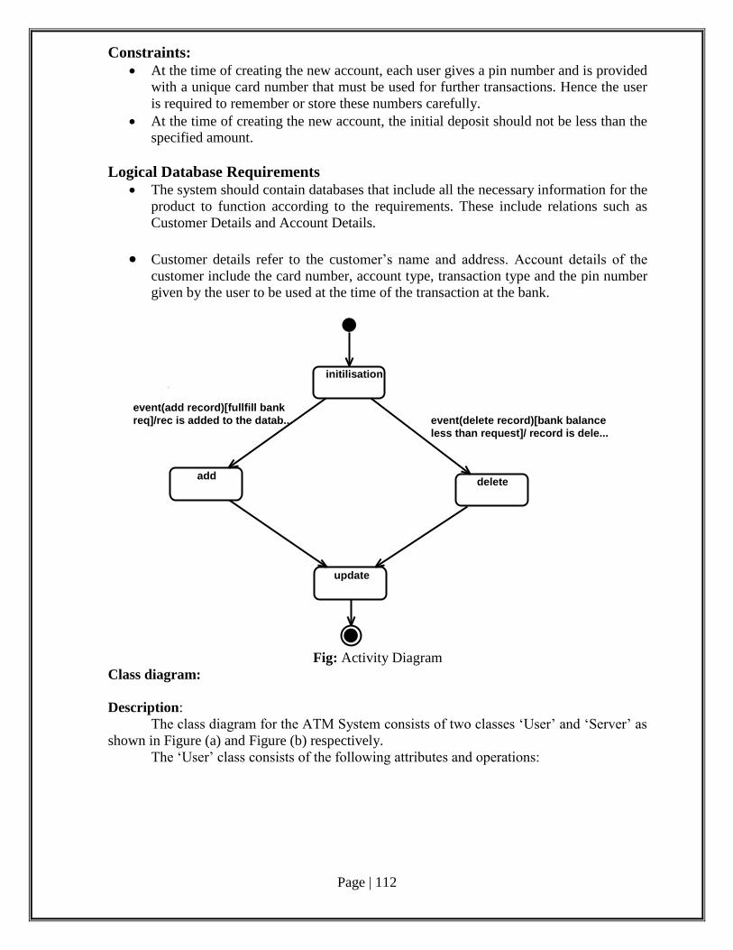
Page | 112
Constraints:
At the time of creating the new account, each user gives a pin number and is provided
with a unique card number that must be used for further transactions. Hence the user
is required to remember or store these numbers carefully.
At the time of creating the new account, the initial deposit should not be less than the
specified amount.
Logical Database Requirements
The system should contain databases that include all the necessary information for the
product to function according to the requirements. These include relations such as
Customer Details and Account Details.
Customer details refer to the customer’s name and address. Account details of the
customer include the card number, account type, transaction type and the pin number
given by the user to be used at the time of the transaction at the bank.
Fig: Activity Diagram
Class diagram:
Description:
The class diagram for the ATM System consists of two classes ‘User’ and ‘Server’ as
shown in Figure (a) and Figure (b) respectively.
The ‘User’ class consists of the following attributes and operations:
initilisation
add delete
update
event(add record)[fullfill bank
req]/rec is added to the datab... event(delete record)[bank balance
less than request]/ record is dele...
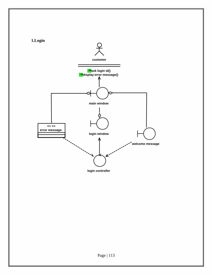
Page | 113
1.Login
login controller
login window
welcome message
customer
ask login id() display error message()
error message. << >>
main window

Page | 114
2. Transaction:
generate report << >>
update database << >>
error message. << >>
customer
ask login id() display error message()
transaction screen
initiate transaction() provide information()
<< >>
+1...*
+1
+1
+1
+0...*
+1
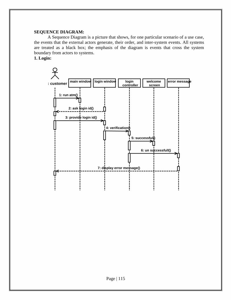
Page | 115
SEQUENCE DIAGRAM: A Sequence Diagram is a picture that shows, for one particular scenario of a use case,
the events that the external actors generate, their order, and inter-system events. All systems
are treated as a black box; the emphasis of the diagram is events that cross the system
boundary from actors to systems. 1. Login:
: customer main window login window login controller
welcome screen
error message
1: run atm()
2: ask login id()
3: provide login id()
4: verification()
5: successful()
6: un successfull()
7: display error message()
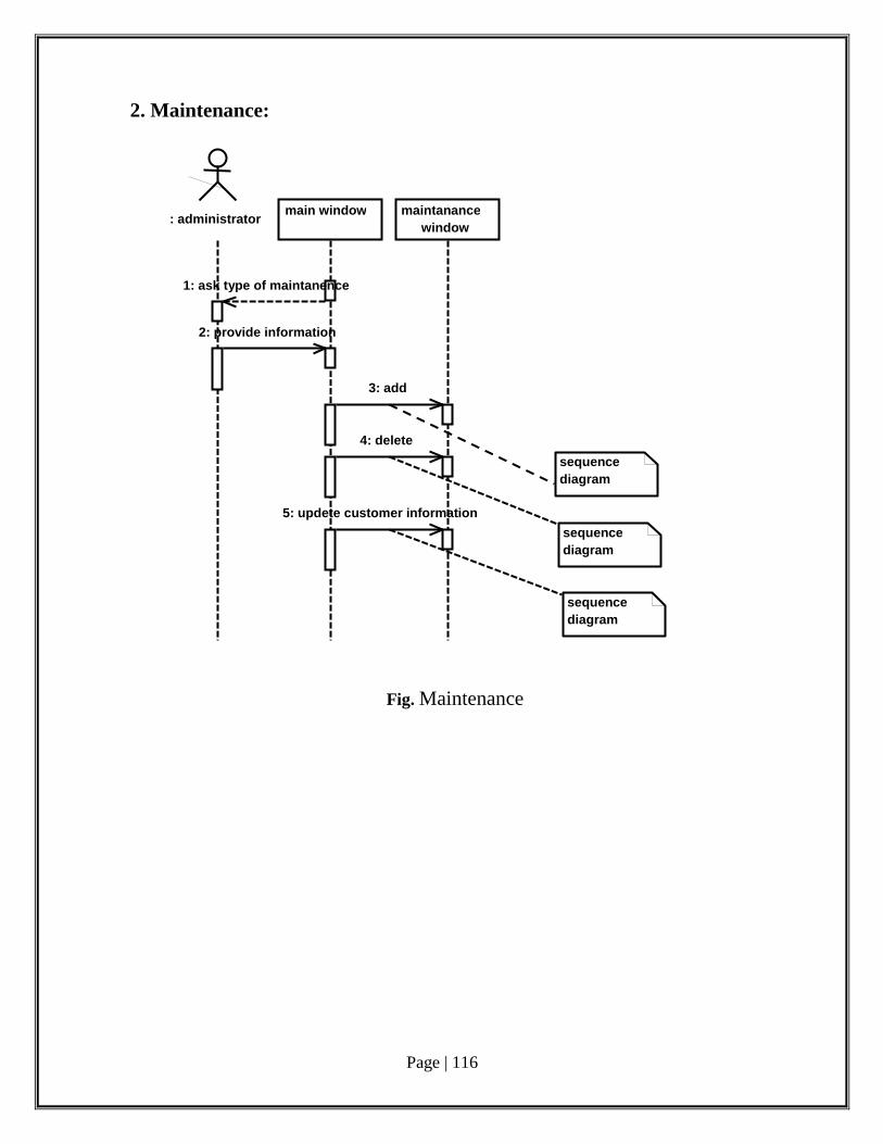
Page | 116
2. Maintenance:
Fig. Maintenance
: administrator main window maintanance
window
1: ask type of maintanence
2: provide information
3: add
4: delete
5: updete customer information
sequence diagram
sequence diagram
sequence diagram
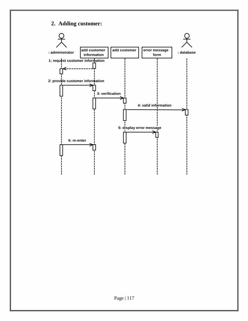
Page | 117
2. Adding customer:
: administrator add customer
information add customer error message
form : database
1: request customer information
2: provide customer information
3: verification
4: valid information
5: display error message
6: re-enter
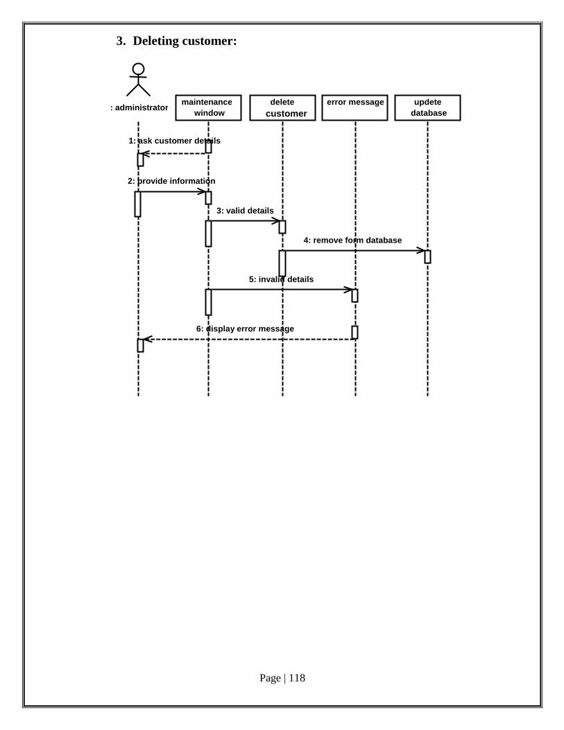
Page | 118
3. Deleting customer:
: administrator maintenance
window delete
customer error message updete
database
1: ask customer details
2: provide information
3: valid details
4: remove form database
5: invalid details
6: display error message
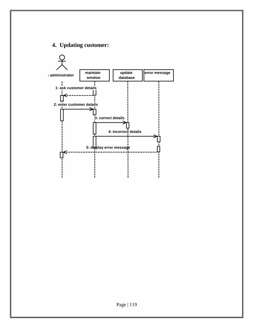
Page | 119
4. Updating customer:
: administrator maintain window
update database
error message
1: ask customer details
2: enter customer details
3: correct details
4: incorrect details
5: display error message
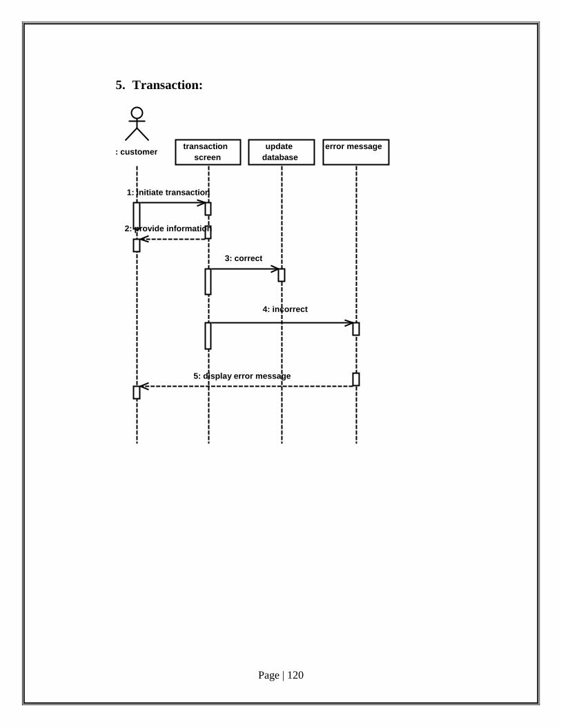
Page | 120
5. Transaction:
: customer transaction
screen update
database error message
1: initiate transaction
2: provide information
3: correct
4: incorrect
5: display error message
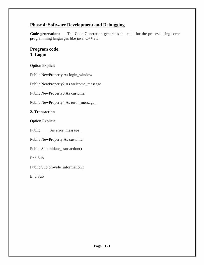
Page | 121
Phase 4: Software Development and Debugging
Code generation: The Code Generation generates the code for the process using some
programming languages like java, C++ etc.
Program code:
1. Login
Option Explicit
Public NewProperty As login_window
Public NewProperty2 As welcome_message
Public NewProperty3 As customer
Public NewProperty4 As error_message_
2. Transaction
Option Explicit
Public ____ As error_message_
Public NewProperty As customer
Public Sub initiate_transaction()
End Sub
Public Sub provide_information()
End Sub
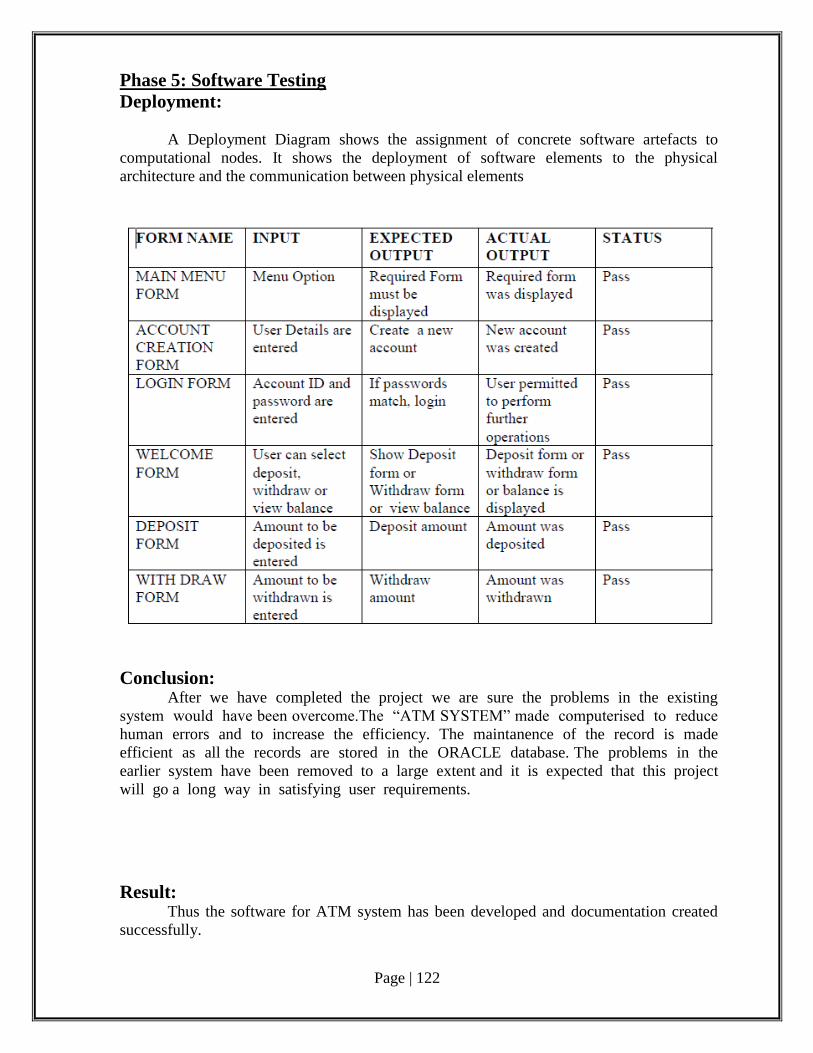
Page | 122
Phase 5: Software Testing
Deployment:
A Deployment Diagram shows the assignment of concrete software artefacts to
computational nodes. It shows the deployment of software elements to the physical
architecture and the communication between physical elements
Conclusion: After we have completed the project we are sure the problems in the existing
system would have been overcome.The “ATM SYSTEM” made computerised to reduce
human errors and to increase the efficiency. The maintanence of the record is made
efficient as all the records are stored in the ORACLE database. The problems in the
earlier system have been removed to a large extent and it is expected that this project
will go a long way in satisfying user requirements.
Result: Thus the software for ATM system has been developed and documentation created
successfully.

Page | 123
Post Lab Questions:
1. Which granularity level of testing checks the behavior of module cooperation?
a) Unit Testing
b) Integration Testing
c) Acceptance Testing
d) Regression Testing
2. Which test refers to the retesting of a unit, integration and system after modification, in
order to ascertain that the change has not introduced new faults?
a) Regression Test
b) Smoke Test
c) Alpha Test
d) Beta Test.
3. Which of the following is a black box testing strategy?
a) All Statements Coverage
b) Control Structure Coverage
c) Cause-Effect Graphs
d) All Paths Coverage
4. A set of inputs, execution preconditions and expected outcomes is known as a
a) Test plan
b) Test case
c) Test document
d) Test Suite
5. In which test design each input is tested at both ends of its valid range and just outside its
valid range?
a) Boundary value testing
b) Equivalence class partitioning
c) Boundary value testing AND Equivalence class partitioning
d) Decision tables
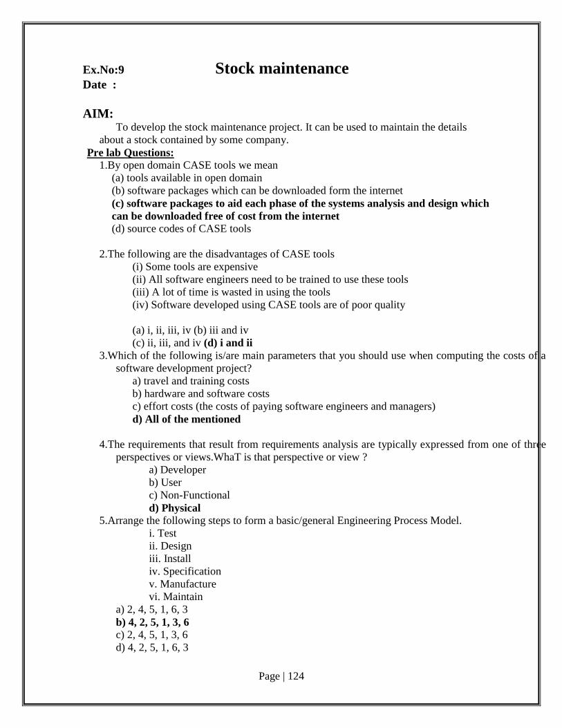
Page | 124
Ex.No:9 Stock maintenance Date :
AIM: To develop the stock maintenance project. It can be used to maintain the details
about a stock contained by some company.
Pre lab Questions:
1.By open domain CASE tools we mean
(a) tools available in open domain
(b) software packages which can be downloaded form the internet
(c) software packages to aid each phase of the systems analysis and design which
can be downloaded free of cost from the internet
(d) source codes of CASE tools
2.The following are the disadvantages of CASE tools
(i) Some tools are expensive
(ii) All software engineers need to be trained to use these tools
(iii) A lot of time is wasted in using the tools
(iv) Software developed using CASE tools are of poor quality
(a) i, ii, iii, iv (b) iii and iv
(c) ii, iii, and iv (d) i and ii
3.Which of the following is/are main parameters that you should use when computing the costs of a
software development project?
a) travel and training costs
b) hardware and software costs
c) effort costs (the costs of paying software engineers and managers)
d) All of the mentioned
4.The requirements that result from requirements analysis are typically expressed from one of three
perspectives or views.WhaT is that perspective or view ?
a) Developer
b) User
c) Non-Functional
d) Physical
5.Arrange the following steps to form a basic/general Engineering Process Model.
i. Test
ii. Design
iii. Install
iv. Specification
v. Manufacture
vi. Maintain
a) 2, 4, 5, 1, 6, 3
b) 4, 2, 5, 1, 3, 6
c) 2, 4, 5, 1, 3, 6
d) 4, 2, 5, 1, 6, 3
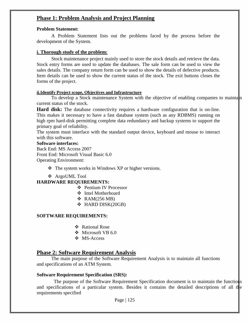
Page | 125
Phase 1: Problem Analysis and Project Planning
Problem Statement:
A Problem Statement lists out the problems faced by the process before the
development of the System.
i. Thorough study of the problem:
Stock maintenance project mainly used to store the stock details and retrieve the data.
Stock entry forms are used to update the databases. The sale form can be used to view the
sales details. The company return form can be used to show the details of defective products.
Item details can be used to show the current status of the stock. The exit buttons closes the
forms of the project.
ii.Identify Project scope, Objectives and Infrastructure
To develop a Stock maintenance System with the objective of enabling companies to maintain
current status of the stock.
Hard disk: The database connectivity requires a hardware configuration that is on-line.
This makes it necessary to have a fast database system (such as any RDBMS) running on
high rpm hard-disk permitting complete data redundancy and backup systems to support the
primary goal of reliability.
The system must interface with the standard output device, keyboard and mouse to interact
with this software.
Software interfaces: Back End: MS Access 2007
Front End: Microsoft Visual Basic 6.0
Operating Environment:
The system works in Windows XP or higher versions.
ArgoUML Tool
HARDWARE REQUIREMENTS:
Pentium IV Processor
Intel Motherboard
RAM(256 MB)
HARD DISK(20GB)
SOFTWARE REQUIREMENTS:
Rational Rose
Microsoft VB 6.0
MS-Access
Phase 2: Software Requirement Analysis The main purpose of the Software Requirement Analysis is to maintain all functions
and specifications of an ATM System.
Software Requirement Specification (SRS):
The purpose of the Software Requirement Specification document is to maintain the functions
and specifications of a particular system. Besides it contains the detailed descriptions of all the
requirements specified
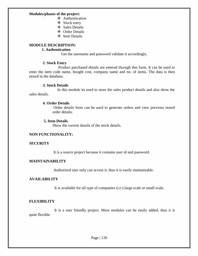
Page | 126
Modules/phases of the project:
Authentication
Stock entry
Sales Details
Order Details
Item Details
MODULE DESCRIPTION:
1. Authentication Get the username and password validate it accordingly.
2. Stock Entry
Product purchased details are entered through this form. It can be used to
enter the item code name, bought cost, company name and no. of items. The data is then
stored in the database.
3. Stock Details In this module its used to store the sales product details and also show the
sales details.
4. Order Details
Order details form can be used to generate orders and view previous stored
order details.
5. Item Details
Show the current details of the stock details.
NON FUNCTIONALITY:
SECURITY
It is a source project because it contains user id and password.
MAINTAINABILITY
Authorized user only can access it, thus it is easily maintainable.
AVAILABILITY
It is available for all type of companies (i.e.) large scale or small scale.
FLEXIBILITY
It is a user friendly project. More modules can be easily added, thus it is
quite flexible.
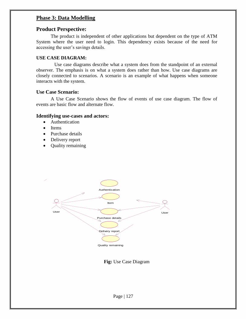
Page | 127
Phase 3: Data Modelling
Product Perspective:
The product is independent of other applications but dependent on the type of ATM
System where the user need to login. This dependency exists because of the need for
accessing the user’s savings details.
USE CASE DIAGRAM:
Use case diagrams describe what a system does from the standpoint of an external
observer. The emphasis is on what a system does rather than how. Use case diagrams are
closely connected to scenarios. A scenario is an example of what happens when someone
interacts with the system.
Use Case Scenario:
A Use Case Scenario shows the flow of events of use case diagram. The flow of
events are basic flow and alternate flow.
Identifying use-cases and actors:
Authentication
Items
Purchase details
Delivery report
Quality remaining
Authentication
Item
Purchase details
Delivery report
User
Quality remaining
User
Fig: Use Case Diagram
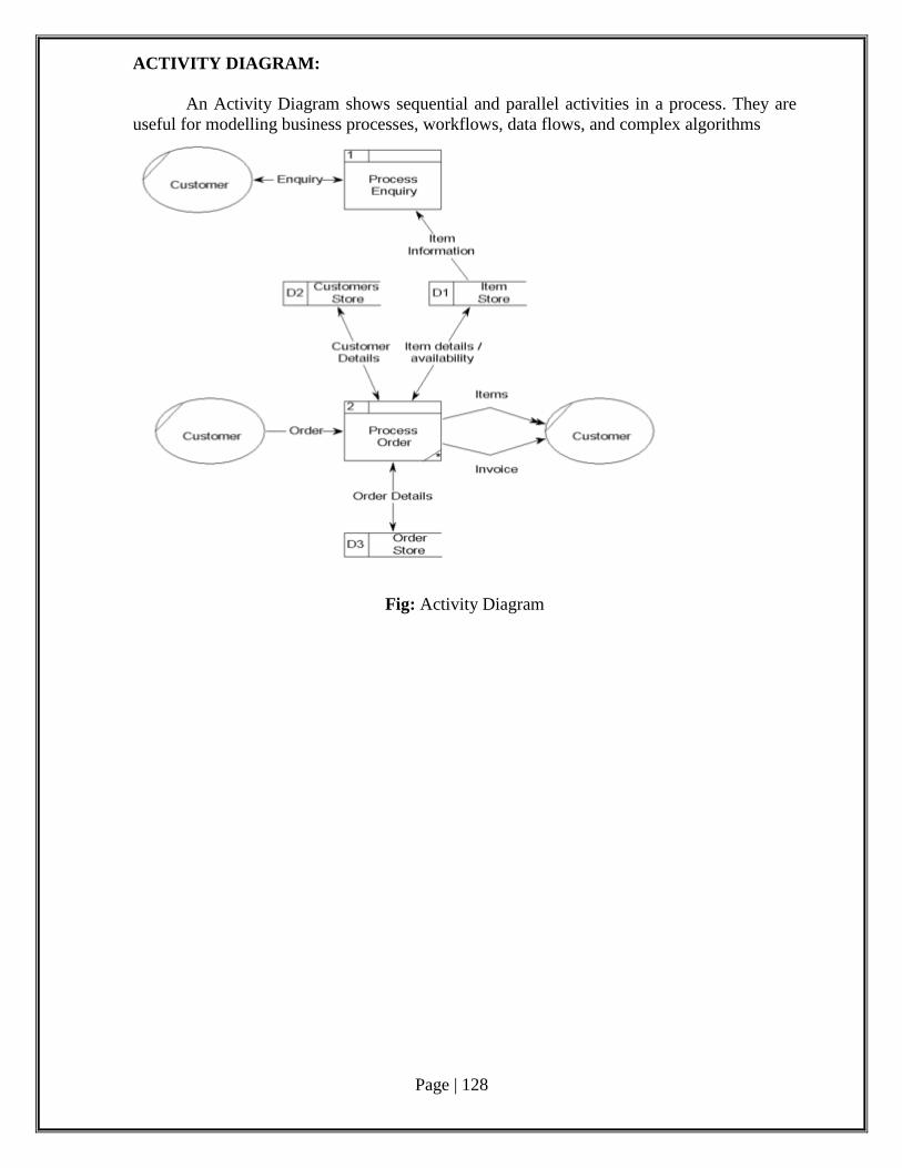
Page | 128
ACTIVITY DIAGRAM:
An Activity Diagram shows sequential and parallel activities in a process. They are
useful for modelling business processes, workflows, data flows, and complex algorithms
Fig: Activity Diagram
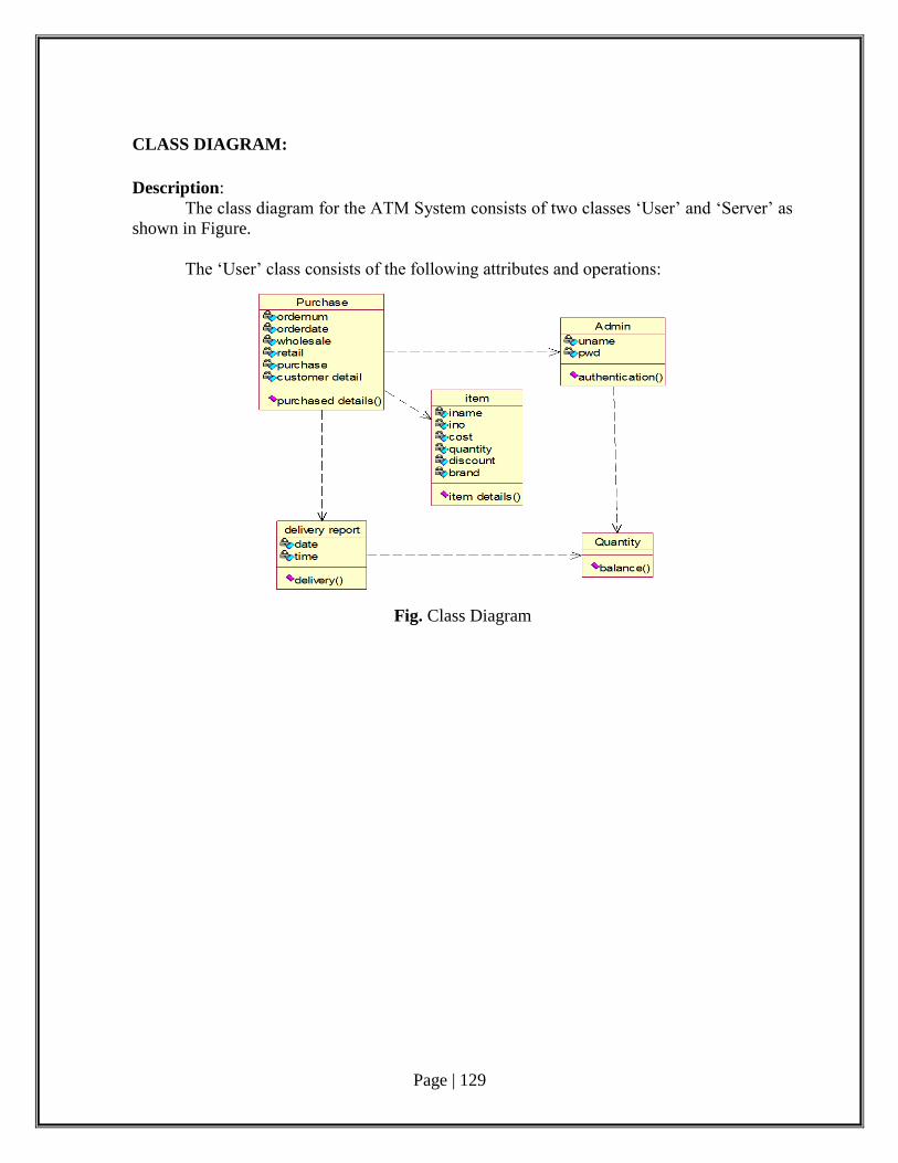
Page | 129
CLASS DIAGRAM:
Description:
The class diagram for the ATM System consists of two classes ‘User’ and ‘Server’ as
shown in Figure.
The ‘User’ class consists of the following attributes and operations:
Fig. Class Diagram
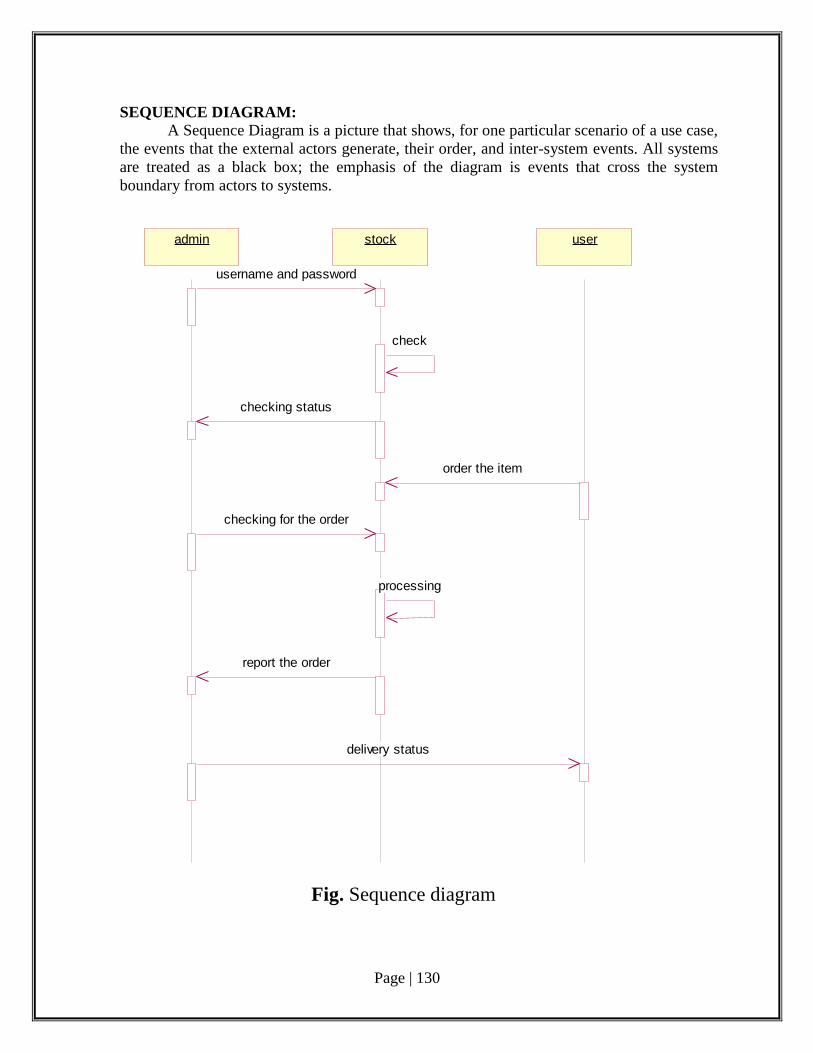
Page | 130
SEQUENCE DIAGRAM: A Sequence Diagram is a picture that shows, for one particular scenario of a use case,
the events that the external actors generate, their order, and inter-system events. All systems
are treated as a black box; the emphasis of the diagram is events that cross the system
boundary from actors to systems.
admin stock user
username and password
check
checking status
order the item
checking for the order
processing
report the order
delivery status
Fig. Sequence diagram
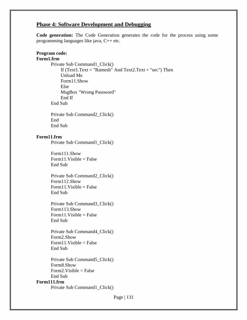
Page | 131
Phase 4: Software Development and Debugging
Code generation: The Code Generation generates the code for the process using some
programming languages like java, C++ etc.
Program code:
Form1.frm
Private Sub Command1_Click()
If (Text1.Text = "Ramesh" And Text2.Text = "sec") Then
Unload Me
Form11.Show
Else
MsgBox "Wrong Password"
End If
End Sub
Private Sub Command2_Click()
End
End Sub
Form11.frm
Private Sub Command1_Click()
Form111.Show
Form11.Visible = False
End Sub
Private Sub Command2_Click()
Form112.Show
Form11.Visible = False
End Sub
Private Sub Command3_Click()
Form113.Show
Form11.Visible = False
End Sub
Private Sub Command4_Click()
Form2.Show
Form11.Visible = False
End Sub
Private Sub Command5_Click()
Form8.Show
Form2.Visible = False
End Sub
Form111.frm
Private Sub Command1_Click()
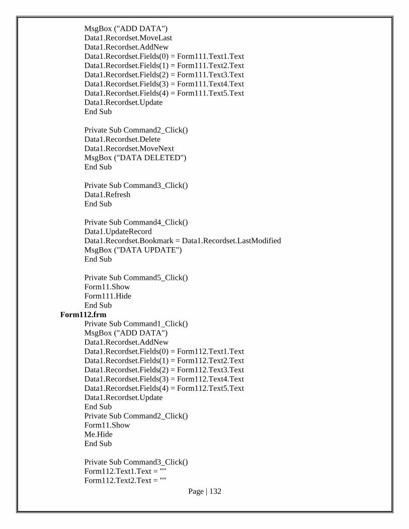
Page | 132
MsgBox ("ADD DATA")
Data1.Recordset.MoveLast
Data1.Recordset.AddNew
Data1.Recordset.Fields(0) = Form111.Text1.Text
Data1.Recordset.Fields(1) = Form111.Text2.Text
Data1.Recordset.Fields(2) = Form111.Text3.Text
Data1.Recordset.Fields(3) = Form111.Text4.Text
Data1.Recordset.Fields(4) = Form111.Text5.Text
Data1.Recordset.Update
End Sub
Private Sub Command2_Click()
Data1.Recordset.Delete
Data1.Recordset.MoveNext
MsgBox ("DATA DELETED")
End Sub
Private Sub Command3_Click()
Data1.Refresh
End Sub
Private Sub Command4_Click()
Data1.UpdateRecord
Data1.Recordset.Bookmark = Data1.Recordset.LastModified
MsgBox ("DATA UPDATE")
End Sub
Private Sub Command5_Click()
Form11.Show
Form111.Hide
End Sub
Form112.frm
Private Sub Command1_Click()
MsgBox ("ADD DATA")
Data1.Recordset.AddNew
Data1.Recordset.Fields(0) = Form112.Text1.Text
Data1.Recordset.Fields(1) = Form112.Text2.Text
Data1.Recordset.Fields(2) = Form112.Text3.Text
Data1.Recordset.Fields(3) = Form112.Text4.Text
Data1.Recordset.Fields(4) = Form112.Text5.Text
Data1.Recordset.Update
End Sub
Private Sub Command2_Click()
Form11.Show
Me.Hide
End Sub
Private Sub Command3_Click()
Form112.Text1.Text = ""
Form112.Text2.Text = ""
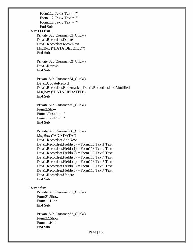
Page | 133
Form112.Text3.Text = ""
Form112.Text4.Text = ""
Form112.Text5.Text = ""
End Sub
Form113.frm
Private Sub Command2_Click()
Data1.Recordset.Delete
Data1.Recordset.MoveNext
MsgBox ("DATA DELETED")
End Sub
Private Sub Command3_Click()
Data1.Refresh
End Sub
Private Sub Command4_Click()
Data1.UpdateRecord
Data1.Recordset.Bookmark = Data1.Recordset.LastModified
MsgBox ("DATA UPDATED")
End Sub
Private Sub Command5_Click()
Form2.Show
Form1.Text1 = " "
Form1.Text2 = " "
End Sub
Private Sub Command6_Click()
MsgBox ("ADD DATA")
Data1.Recordset.AddNew
Data1.Recordset.Fields(0) = Form113.Text1.Text
Data1.Recordset.Fields(1) = Form113.Text2.Text
Data1.Recordset.Fields(2) = Form113.Text3.Text
Data1.Recordset.Fields(3) = Form113.Text4.Text
Data1.Recordset.Fields(4) = Form113.Text5.Text
Data1.Recordset.Fields(5) = Form113.Text6.Text
Data1.Recordset.Fields(6) = Form113.Text7.Text
Data1.Recordset.Update
End Sub
Form2.frm
Private Sub Command1_Click()
Form21.Show
Form11.Hide
End Sub
Private Sub Command2_Click()
Form22.Show
Form11.Hide
End Sub
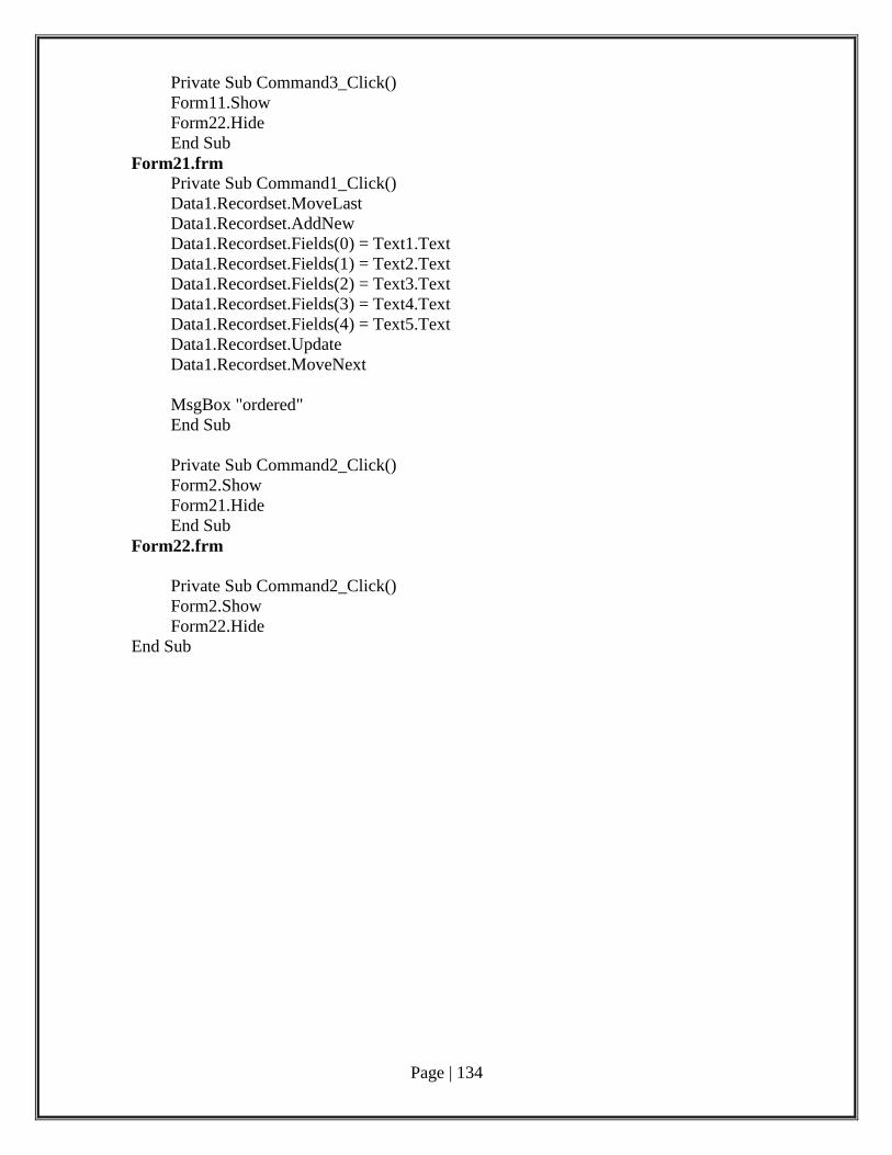
Page | 134
Private Sub Command3_Click()
Form11.Show
Form22.Hide
End Sub
Form21.frm
Private Sub Command1_Click()
Data1.Recordset.MoveLast
Data1.Recordset.AddNew
Data1.Recordset.Fields(0) = Text1.Text
Data1.Recordset.Fields(1) = Text2.Text
Data1.Recordset.Fields(2) = Text3.Text
Data1.Recordset.Fields(3) = Text4.Text
Data1.Recordset.Fields(4) = Text5.Text
Data1.Recordset.Update
Data1.Recordset.MoveNext
MsgBox "ordered"
End Sub
Private Sub Command2_Click()
Form2.Show
Form21.Hide
End Sub
Form22.frm
Private Sub Command2_Click()
Form2.Show
Form22.Hide
End Sub
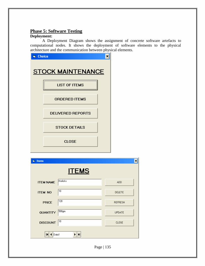
Page | 135
Phase 5: Software Testing Deployment:
A Deployment Diagram shows the assignment of concrete software artefacts to
computational nodes. It shows the deployment of software elements to the physical
architecture and the communication between physical elements.
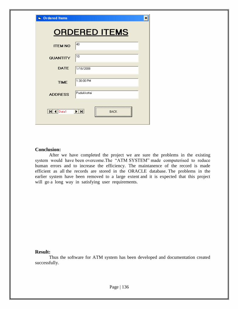
Page | 136
Conclusion: After we have completed the project we are sure the problems in the existing
system would have been overcome.The “ATM SYSTEM” made computerised to reduce
human errors and to increase the efficiency. The maintanence of the record is made
efficient as all the records are stored in the ORACLE database. The problems in the
earlier system have been removed to a large extent and it is expected that this project
will go a long way in satisfying user requirements.
Result: Thus the software for ATM system has been developed and documentation created
successfully.
Page | 137
Post lab questions:
1. Each time a defect gets detected and fixed, the reliability of a software product
(A) increases. (B) decreases.
(C) remains constant. (D) cannot say anything.
2. Aggregation represents
(A) is_a relationship (B) part_of relationship
(C) composed_of relationship (D) none of above
3. Requirements can be refined using
(A) The waterfall model (B) prototyping model
(C) the evolutionary model (D) the spiral model
4. If a program in its functioning has not met user requirements is some way, then it is
(A) an error. (B) a failure.
(C) a fault. (D) a defect.
5. CASE Tool is
(A) Computer Aided Software Engineering
(B) Component Aided Software Engineering
(C) Constructive Aided Software Engineering
(D) Computer Analysis Software Engineering
Page | 138
Ex.No:10 Quiz System Date :
AIM:
To develop software for online quiz system with documentation.
Pre Lab questions:
1. CASE tools are used by industries to
(i) Improve productivity of their software engineers
(ii) Reduce time to develop applications
(iii)Improve documentation
(iv)Automate system analysis
(a) i and ii (b) i and iii
(c) i, ii, and iii (d) ii and iii
2.The current standard tool for designing object oriented systems is called
(a) Unified Modelling Language
(b) Booch Modelling Language
(c) Object Modelling Language
(d) Class, responsibilities and collaborators language
3.A description of each function presented in the DFD is contained in a ________.
a) data flow
b) process specification
c) control specification
d) data store
4._________ defines the properties of a data object and take on one of the three different
characteristics.
a) data object
b) attributes
c) relationships
d) data object and attributes
5.Which of the following provides a concise, unambiguous, and consistent method for documenting
system requirements?
a) CMM
b) ISO-9001
c) CASE tools
d) Formal methods
Page | 139
Phase 1: Problem Analysis and Project Planning
Problem Statement:
A Problem Statement lists out the problems faced by the process before the
development of the System.
i. Thorough study of the problem:
Queue Problem
In order to register for a exam a customer needs to wait in long queues, as all the
customers come to the same spot for registration.
Transport Problem A customer has to travel a long distance from faraway places to where the University
or the Colleges are located.
Loss of Money
A lot of money is spent for the journey and for refreshments by the customer while
travelling to the University or College.
Employees Problem
A lot of Employees has to be recruited in order to handle the large number of
customers.
Need for Branches
The University or the Colleges needs to open many branches at many places in order
to cover the customer.
Maintenance of Data
Difficulty in handling large amount of data, as everything is done manually. So,
misplacement of forms and other errors are possible.
Timing not Flexible
The customer could not register for a course at his/hers feasible timings, as the
University or the College is open only during the office hours.
ii.Identify Project scope, Objectives and Infrastructure To develop an Online Quiz Registration System with the objective of enabling students to
register for a Exam from any part of the world through internet
Operating Environment
The system works in Windows XP or higher versions.
It also needs a SQL server.
Design and Implementation Details
Hardware limitations: There must be at least 64 MB on-board memory.
Page | 140
Control function: in case of errors and service problems, proper error handling
and data recovery mechanism must be included.
Interface to other applications: not applicable
Parallel operations: not applicable
Signal handshake protocols: not applicable
Reliability requirements: data redundancy and use of special/blank characters
must be avoided.
Safety/security constraint: The application must be excited always normally.
Higher order language requirements:c++ or Java
This is not suitable for visually challenged people.
User Interfaces
The user interface of this system is simple and can be understood even by
inexperienced users.
Screen format/organisation: The introductory screen will ask for username and
password. After verification of the details provided by the user, he will be allowed to
access the system and the menu will be displayed.
Window format/organization: Each function will lead to another window. The user
can switch between windows whenever required.
Data Format: The data entered by the users will be alphanumeric.
End message: When there are some errors entering invalid data, error message will
be displayed.
Hardware Interfaces
There must be a minimum of 128 MB RAM, 40 GB HDD
Software Interfaces
The operating system used is windows XP or higher version and the database
management software is SQL server 2000.
Phase 2: Software Requirement Analysis The main purpose of the Software Requirement Analysis is to maintain all functions
and specifications of an ATM System.
Software Requirement Specification (SRS):
The purpose of the Software Requirement Specification document is to maintain the functions
and specifications of a particular system. Besides it contains the detailed descriptions of all the
requirements specified
Modules/phases of the project:
The Scope of Online exam Registration System is:
User should be able to:
Sign-Up if not an already registered user.
Login to the system using a Login-ID and password.
Page | 141
Change the password after logging in, if necessary.
See the vacancy for the exam.
View exam details.
Choose the desired and the available exam.
Confirm the choice by registering for the exam.
A mail should be sent to the concerned persons e-mail ID about the
confirmation of registration.
The Login ID and the Password should be sent to the mentioned e-mail
address if a new account is created.
System should automatically show the exam details after registering for
the particular exam.
Functional Requirements
The functional requirement of the project includes:
Creating separate account for different Users.
User then logs in to the system using his/her Login ID and Password.
Allowing the User to view the availability of the desired exam.
Allowing the User to choose the desired exam based on availability.
The User then registers for the exam by filling a form.
The server then checks the form, to verify if all the mandatory details are entered.
Finally the exam details are displayed to the User by the Server.
Other Functional Requirements
Performance Requirements
More than one user of the system cannot access the system at the same time. The
course selection can be performed under certain constraints or else the system should behave
in a graceful manner. Entering illegal details, accessing personal details of other users should
be prevented.
Safety and Security Requirements
The User name and Password should match and valid.
The User should provide valid personal information.
Phase 3: Data Modelling
Product Perspective:
The product is independent of other applications but dependent on registration
websites where the user need to login. This dependency exists because of the need for
accessing the user’s details and exam details.
Page | 142
Product Functionality
Signing up and becoming an authenticated User: The user has to give
some personal details to sign up and to become an authenticated user in
order to use the system
Login to the system: Login to the system using his/her Login ID and
Password date. The Server then validates the Login ID and Password and
allows the user access the system.
Check Availability of the course: User could check the availability of the
desired exam and then go for the registration of the course.
Selection of course: Based on the availability of the courses the user
chooses the desired exam.
Registration: After selecting a particular course the user needs to fill a
form to register for the exam.
View course details: After registering for the exam, the exam details are
displayed to the user.
USE CASE DIAGRAM:
Use case diagrams describe what a system does from the standpoint of an external
observer. The emphasis is on what a system does rather than how. Use case diagrams are
closely connected to scenarios. A scenario is an example of what happens when someone
interacts with the system.
Use Case Scenario:
A Use Case Scenario shows the flow of events of use case diagram. The flow of
events are basic flow and alternate flow.
Identifying use-cases and actors:
Rough Use Case
1. Sign-Up
2. Login
3. System
4. Displaying exam details
5. online Payment
6. Registration
7. Logout
8. printer
Actors
1. User
2. Server
3. PayPal
Finalized Use Cases
1. Login
2. Displaying exam details
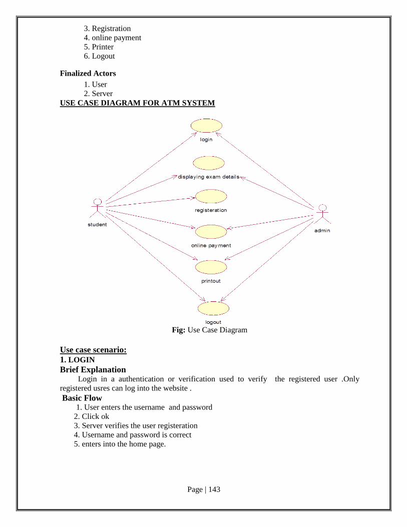
Page | 143
3. Registration
4. online payment
5. Printer
6. Logout
Finalized Actors
1. User
2. Server
USE CASE DIAGRAM FOR ATM SYSTEM
Fig: Use Case Diagram
Use case scenario:
1. LOGIN
Brief Explanation Login in a authentication or verification used to verify the registered user .Only
registered usres can log into the website .
Basic Flow 1. User enters the username and password
2. Click ok
3. Server verifies the user registeration
4. Username and password is correct
5. enters into the home page.
Page | 144
Alternative Flow
1. User enters the username and password
2. Click ok
3. Server verifies the user registration
4. Username and password is incorrect, Re-enter the username and password
5. Enter into the login page.
Precondition: Registered user
Postcondition: Enters into the homepage of the website
2 .DISPLAY EXAM DETAILS
Brief Description
It is a function in which exam details are displayed
It will display the amount of fee,exam date ,exam duration etc.
Basic Flow
1. After entering into homepage click ON view exam details.
2. It will display the mainpage of exam details
3. Each exam may contain separate pages to view exam details
Precondition: Home page of the website
Postcondition: Main page of exam details
3. REGISTRATION
Brief Description
In this usecase we will enter the user’s personal details like name, age, sex,
college and also we will select the exam which we are going to register.
Basic Flow
1. After viewing exam details, select the exam which we have to register.
2. Then enter age, name, exam-date, sex.
3. Then click Ok.
4. Entered data is verified with server data.
5. It will display registration is completed .
6. Enter the page to pay money .
Alternative Flow
1. After viewing exam details ,select the exam which we have to register ..
2. Then enter age, name, exam-date, sex
3. Then click OK.
4. Entered data is verified, then it will return entered exam-date is not present, Re-
enter another date
5. Enter into the page to fill details.
Precondition: Home page of exam details
Postcondition: Enter into the page to pay money by online.
4. ONLINEPAY
Brief Description
It is pay the money by online, we can pay the money by online by using credit
card, Debit card, cheque etc. It is easy to use online payment .
Page | 145
Basic Flow
1. After entering into the page to pay money, we have to close the Credit /Debit.
2. Fill the details credit /Debit like account holder name, pin no ,card no , valid form.
3. Click OK or Submit.
4. Verify the card details with server.
5. The returns payment completed.
6. Then show the acknowledge (hall ticket)
Alternative Flow: A1
1. After entering into the page to pay money , we have to close credit/Debit.
2. Fill details like account holder name , pin no , card no , valid form .
3. Click OK.
4. Verifies the card with server.
5. Returns card is not valid.
6. Enters into the home page of payment
Alternative Flow: A2
1. After entering into the page to pay money, we have to close credit/Debit.
2. Fill details like account holder name, pin no, card no, valid form.
3. Click Ok.
4. Verifies card is not valid.
5. Returns card no is invalid.
6. Enters into the home page of payment.
Precondition: Home page for payment
Postcondition: Acknowledgement will receive
5. PRINTER
Brief Description
It is used to print the Acknowledgment by using printer , we can take copy of
Acknowledgement .
Basic Flow
1. After viewing the acknowledgment page, then give the page to print .
2. Click OK
3. We will receive the soft copy of acknowledgment.
4. Go to logout.
Alternative Flow
1. After receiving the acknowledgment page then give the page to print .
2. Click Ok
3. It will check the server .
4. Shows entered no page is wrong .
5. Return to print page .
Precondition: Acknowledgment page.
Postcondition: Logout page
6. LOGOUT
Brief Description
It is used to come out of current website .
Basic Flow
1. After entering into logout page.
Page | 146
2. Click On logout.
3. At last we will come out of website.
Precondition Logout page.
Postcondition Closing the website.
ACTIVITY DIAGRAM:
An Activity Diagram shows sequential and parallel activities in a process. They are
useful for modeling business processes, workflows, data flows, and complex algorithms.
Description The activity diagram for Online Exam Registration System is drawn as shown in the
Figure . It consists of eight activities and five decisions.
In the first activity the user sign-up’s followed by a decision which checks whether
the user name is available. If ‘yes’ it proceeds to the next step, if ‘no’ the above activity is
performed again. The next step consists of a decision which checks whether all mandatory
details are entered. If ‘yes’ it proceeds to the next step, if ‘no’ the above activity is performed
again.
The next step consists of an activity where the user enters the login page, followed by
another activity where user enters Login ID and Password. The next step consists of a
decision where it checks whether Login ID and Password are authentic. If ‘yes’ it proceeds to
the next step, if no the above activity is performed again.
The next step consists of an activity where the user enters exam selection page
followed by another activity where user selects a exam. The next step consists of a decision
where it checks whether the selected exam is available or not. If available it proceeds to next
step, if no the above activity is performed again.
The next step consists of an activity where the user enters registration page followed
by another activity where user enters the details of the student. The next step consists of a
decision where it checks whether all mandatory details are entered or not. If ‘yes’ it proceeds
to next step, if ‘no’ the above activity is performed again.
The next step consists of an activity where the user views the exam details. The
Activity is terminated finally.
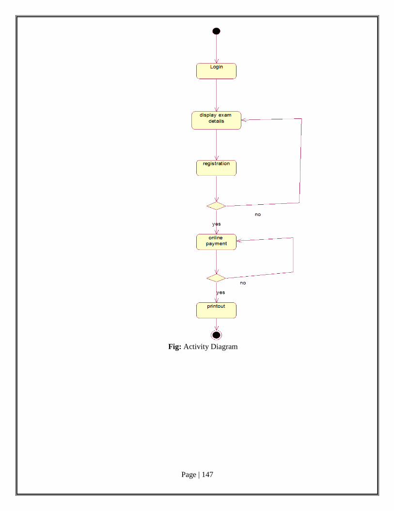
Page | 147
Fig: Activity Diagram
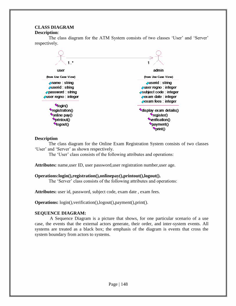
Page | 148
CLASS DIAGRAM
Description:
The class diagram for the ATM System consists of two classes ‘User’ and ‘Server’
respectively.
Description
The class diagram for the Online Exam Registration System consists of two classes
‘User’ and ‘Server’ as shown respectively.
The ‘User’ class consists of the following attributes and operations:
Attributes: name,user ID, user password,user registration number,user age.
Operations:login(),registration(),onlinepay(),printout(),logout(). The ‘Server’ class consists of the following attributes and operations:
Attributes: user id, password, subject code, exam date , exam fees.
Operations: login(),verification(),logout(),payment(),print().
SEQUENCE DIAGRAM:
A Sequence Diagram is a picture that shows, for one particular scenario of a use
case, the events that the external actors generate, their order, and inter-system events. All
systems are treated as a black box; the emphasis of the diagram is events that cross the
system boundary from actors to systems.
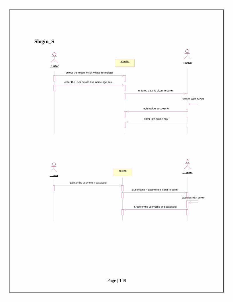
Page | 149
Slogin_S
: :user : :user
screenscreen : :server : :server
1:enter the usernme n password
2:username n password is send to server
3:verifies with server
4.reenter the username and password
: :user : :user
screen:screen: : :server : :server
select the exam which v have to register
enter the user details like name,age,sex...
entered data is given to server
verifies with server
registration successful
enter into online pay
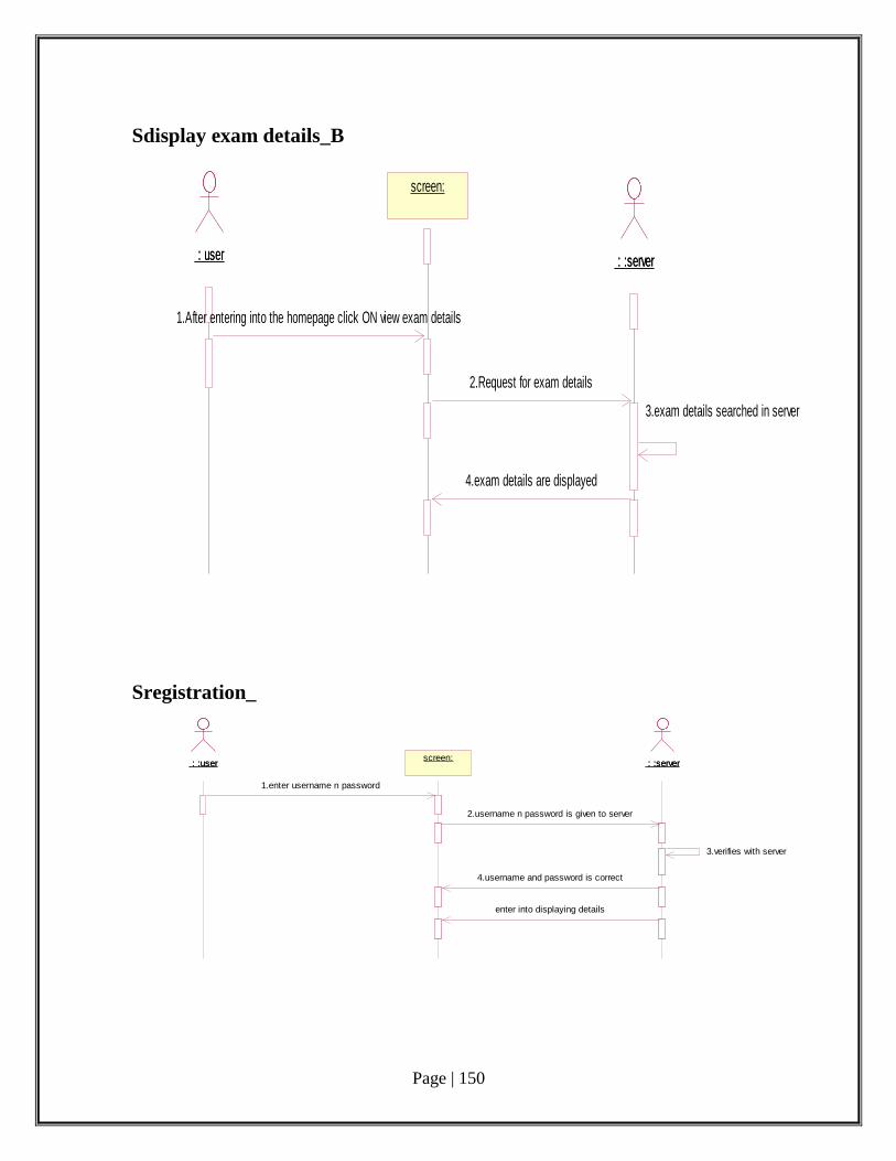
Page | 150
Sdisplay exam details_B
: user : user
screen:screen:
: :server : :server
1.After entering into the homepage click ON view exam details
2.Request for exam details
4.exam details are displayed
3.exam details searched in server
Sregistration_
: :user : :userscreen:screen:
: :server : :server
1.enter username n password
2.username n password is given to server
3.verifies with server
4.username and password is correct
enter into displaying details

Page | 151
Sregistration_A
: :user : :user : :server : :server
1.select the exam to register
2.enter the user details
3.entered data is send to server
4.verifies with server
5.reenter the exam details
: user : userscreen:screen: : :server : :server
user enters the credit card details
fill details like acc holder name and pin no
send request to server
data is verified
payment completed
shows the ACK page
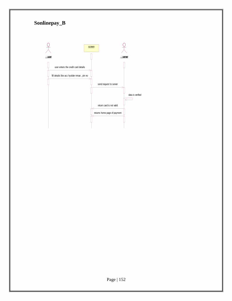
Page | 152
Sonlinepay_B
: :user : :user
screenscreen
: :server : :server
user enters the credit card details
fill details like acc hyolder nmae , pin no
send request to server
data is verified
return card is not valid
returns home page of payment
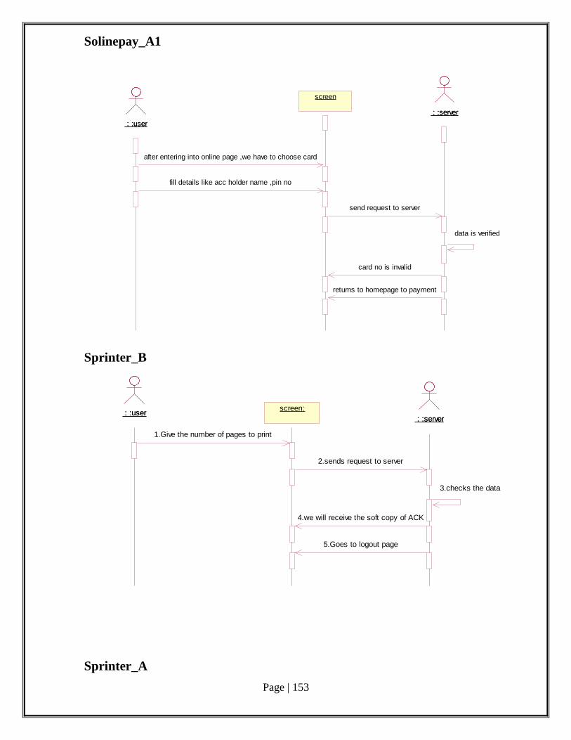
Page | 153
Solinepay_A1
: :user : :user
screenscreen
: :server : :server
after entering into online page ,we have to choose card
fill details like acc holder name ,pin no
send request to server
data is verified
card no is invalid
returns to homepage to payment
Sprinter_B
: :user : :userscreen:screen:
: :server : :server
1.Give the number of pages to print
2.sends request to server
3.checks the data
4.we will receive the soft copy of ACK
5.Goes to logout page
Sprinter_A
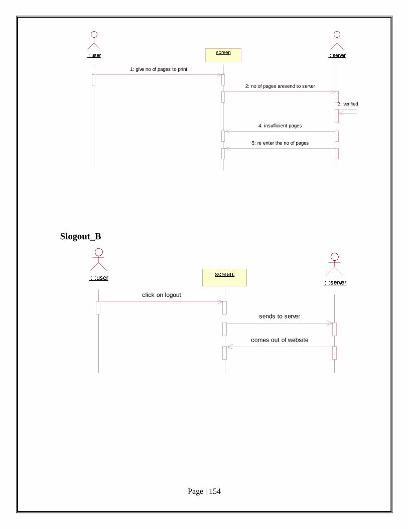
Page | 154
: user : userscreenscreen
: server : server
1: give no of pages to print
2: no of pages aresend to server
3: verified
4: insufficient pages
5: re enter the no of pages
Slogout_B
: :user : :userscreen:screen:
: :server : :server
click on logout
sends to server
comes out of website
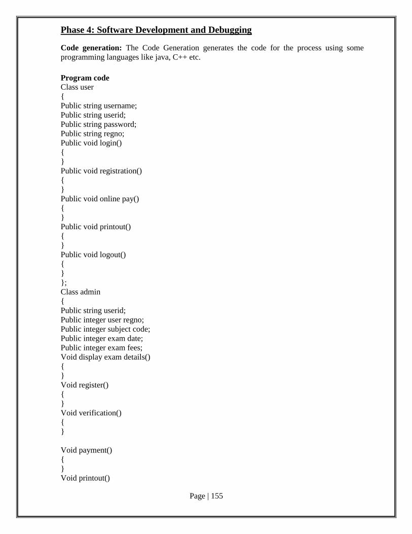
Page | 155
Phase 4: Software Development and Debugging Code generation: The Code Generation generates the code for the process using some
programming languages like java, C++ etc.
Program code Class user
{
Public string username;
Public string userid;
Public string password;
Public string regno;
Public void login()
{
}
Public void registration()
{
}
Public void online pay()
{
}
Public void printout()
{
}
Public void logout()
{
}
};
Class admin
{
Public string userid;
Public integer user regno;
Public integer subject code;
Public integer exam date;
Public integer exam fees;
Void display exam details()
{
}
Void register()
{
}
Void verification()
{
}
Void payment()
{
}
Void printout()
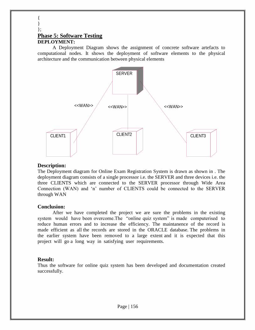
Page | 156
{
}
};
Phase 5: Software Testing DEPLOYMENT:
A Deployment Diagram shows the assignment of concrete software artefacts to
computational nodes. It shows the deployment of software elements to the physical
architecture and the communication between physical elements
SERVER
CLIENT1 CLIENT2 CLIENT3
<<WAN>> <<WAN>> <<WAN>>
Description: The Deployment diagram for Online Exam Registration System is drawn as shown in . The
deployment diagram consists of a single processor i.e. the SERVER and three devices i.e. the
three CLIENTS which are connected to the SERVER processor through Wide Area
Connection (WAN) and ‘n’ number of CLIENTS could be connected to the SERVER
through WAN
Conclusion: After we have completed the project we are sure the problems in the existing
system would have been overcome.The “online quiz system” is made computerised to
reduce human errors and to increase the efficiency. The maintanence of the record is
made efficient as all the records are stored in the ORACLE database. The problems in
the earlier system have been removed to a large extent and it is expected that this
project will go a long way in satisfying user requirements.
Result: Thus the software for online quiz system has been developed and documentation created
successfully.
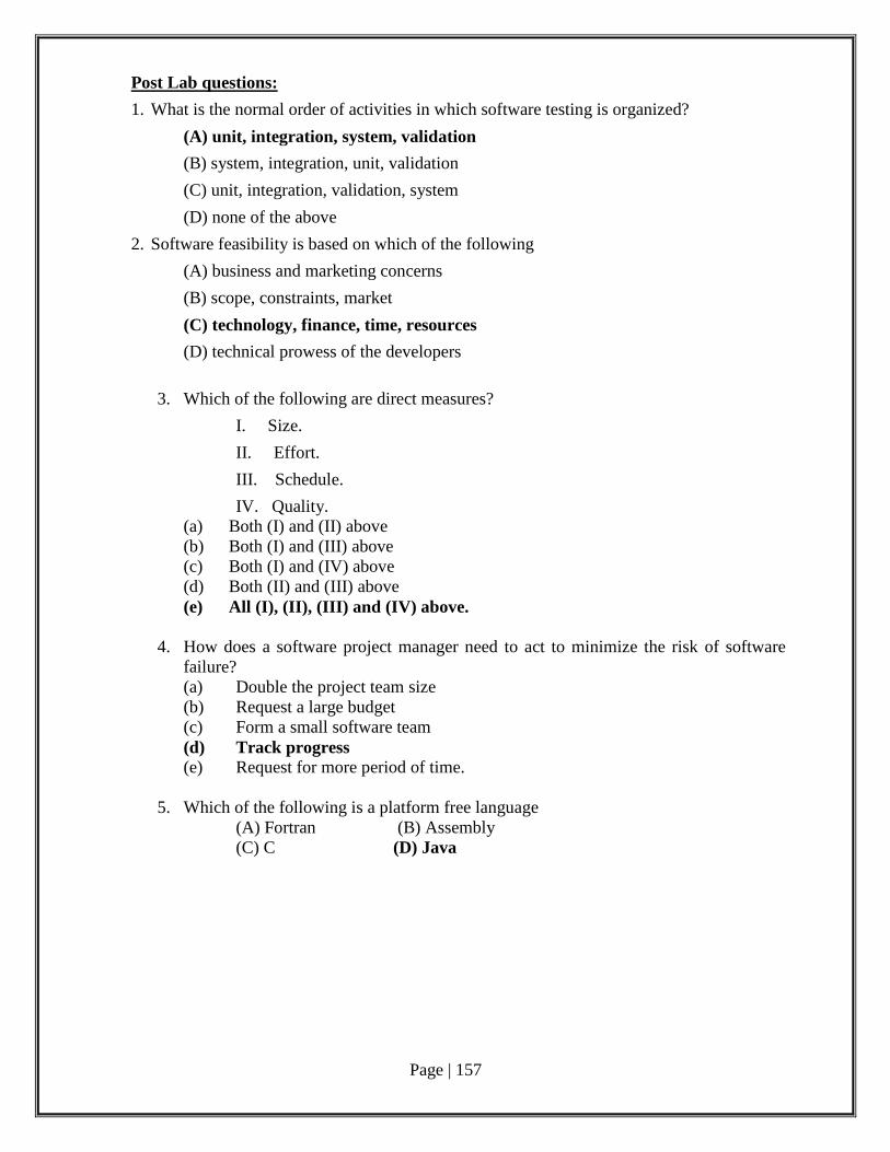
Page | 157
Post Lab questions:
1. What is the normal order of activities in which software testing is organized?
(A) unit, integration, system, validation
(B) system, integration, unit, validation
(C) unit, integration, validation, system
(D) none of the above
2. Software feasibility is based on which of the following
(A) business and marketing concerns
(B) scope, constraints, market
(C) technology, finance, time, resources
(D) technical prowess of the developers
3. Which of the following are direct measures?
I. Size.
II. Effort.
III. Schedule.
IV. Quality.
(a) Both (I) and (II) above
(b) Both (I) and (III) above
(c) Both (I) and (IV) above
(d) Both (II) and (III) above
(e) All (I), (II), (III) and (IV) above.
4. How does a software project manager need to act to minimize the risk of software
failure?
(a) Double the project team size
(b) Request a large budget
(c) Form a small software team
(d) Track progress
(e) Request for more period of time.
5. Which of the following is a platform free language
(A) Fortran (B) Assembly
(C) C (D) Java
Page | 158
Ex.No:11 E-Mail based client recruitment system Date:
AIM:
To develop a software for an E-Mail based client recruitment system with documentation.
Pre Lab Questions:
1. The individual or organisation who wants a product to be developed is known as the:
(a) Developer (b) User (c) Contractor (d) Initiator (e) Client.
2. In the maintenance phase the product must be tested against previous test cases. This
is known as __________ testing. (a) Unit (b) Integration (c) Regression (d) Module (e) Beta.
3. An example of the risk involved in software development is
(a) Key personnel may resign before the product is complete
(b) The manufacturer of critical components (e.g. the hardware associated with a
real-time system) may go bankrupt
(c) Technology changes may render the product obsolete
(d) Competitors may market a fully functional lower-cost equivalent package
(e) All of these are risks involved in software development.
4. A design is said to be a good design if the components are
(a) Strongly coupled
(b) Weakly cohesive
(c) Strongly coupled and Weakly cohesive
(d) Strongly coupled and strongly cohesive
(e) Strongly cohesive and weakly coupled.
5. In the classical chief programmer team approach, the team member responsible for
maintaining the detailed design and coding is
(a) The chief programmer
(b) The programming secretary
(c) A specialized function that exists outside 'the team'
(d) The individual coder (i.e. programmer)
(e) The back-up programmer.
Page | 159
Phase 1: Problem Analysis and Project Planning
i. Thorough study of the problem:
The recruitment system allows the job seekers to enroll their names through the
process of registration. The employee also can get the list of available candidates and
shortlist for their company requirement. Once the applicant enrolls he receives an id, which
helps him in further Correspondence. A fees amount is received from the job seekers for
enrollment. This system makes the task of the job seeker easier rather than waiting in queue
for enrollment. This also reduces the time consumption for both for the job seeker and
employee.
ii.Identify Project scope, Objectives and Infrastructure
• The System provides an online interface to the user where they can fill in their personal
details and submit the necessary documents (may be by scanning).
• The authority concerned with the issue of recruitment can use this system to reduce his
workload and process the application in a speedy manner.
• Provide a communication platform between the applicant and the administrator.
• Transfer of data between the Recruitment Issuing Authority and the Local Police for
verification of applicant's information.
• Users/Applicants will come to know their status of application and the date in which they
must subject themselves for manual document verification.
Infrastructure
Hardware Interfaces:
There must be a minimum of 128 MB RAM, 40 GB HDD
Software Interfaces:
The operating system used is windows XP or higher version and the open source ArgoUML
the database management software is SQL server 2000.
Operating Environment:
The system works in Windows XP or higher versions.
ArgoUML Tool
Design and Implementation Details:
Hardware limitations: There must be at least 64 MB on-board memory.
Control function: in case of errors and service problems, proper error handling and
data recovery mechanism must be included.
Interface to other applications: not applicable
Parallel operations: not applicable
Signal handshake protocols: not applicable
Reliability requirements: data redundancy and use of special/blank characters must
be avoided.
Safety/security constraint: The application must be excited always normally.
Higher order language requirements: C++ or Java
Page | 160
Phase 2: Software Requirement Analysis
Recruitment Automation System is an interface between the Applicant and the Authority
responsible for the Issue of Recruitment. It aims at improving the efficiency in the Issue of
Recruitment and reduces the complexities involved in it to the maximum possible extent.
PURPOSE
If the entire process of 'Issue of Recruitment' is done in a manual manner then it
would takes several months for the recruitment to reach the applicant. Considering the fact
that the number of applicants for recruitment is increasing every year, an Automated System
becomes essential to meet the demand. So this system uses several programming and
database techniques to elucidate the work involved in this process. As this is a matter of
National Security, the system has been carefully verified and validated in order to satisfy it.
DEFINITIONS, ACRONYMS AND THE ABBREVIATIONS
• Administrator - Refers to the super user who is the Central Authority who has been
vested with the privilege to manage the entire system. It can be any higher official in the
Regional Recruitment Office of Ministry of External Affairs.
• Applicant - One who wishes to obtain the Recruitment.
• PAS - Refers to this Recruitment Automation System.
• HTML - Markup Language used for creating web pages.
• J2EE – Java 2 Enterprise Edition is a programming platform java platform for
developing and running distributed java applications.
• HTTP - Hyper Text Transfer Protocol.
•TCP/IP – Transmission Control Protocol/Internet Protocol is the communication
protocol used to connect hosts on the Internet.
TECHNOLOGIES TO BE USED
• HTML
• JSP
• Javascript
• Java
• XML
• AJAX
TOOLS TO BE USED
• Eclipse IDE (Integrated Development Environment)
• Rational Rose tool (for developing UML Patterns)
PRODUCT PERSPECTIVE
The PAS acts as an interface between the 'applicant' and the 'administrator'. This
system tries to make the interface as simple as possible and at the same time not risking the
security of data stored in. This minimizes the time duration in which the user receives the
recruitment.
Page | 161
SOFTWARE INTERFACE
• Front End Client - The applicant and Administrator online interface is built using
JSP and HTML. The Administrators's local interface is built using Java.
• Web Server - Glassfish application server (SQL Corporation).
• Back End - SQL database.
HARDWARE INTERFACE
The server is directly connected to the client systems. The client systems have access
to the database in the server.
SYSTEM FUNCTIONS
• Secure Registration of information by the Applicants.
• Schedule the applicants an appointment for manual verification of original
documents.
• Panel for Recruitment Application Status Display by the Administrator.
• SMS and Mail updates to the applicants by the administrator.
• Administrator can generate reports from the information and is the only authorized
personnel to add the eligible application information to the database.
USER CHARACTERISTICS
• Applicant - They are the people who desires to obtain the recruitment and submit
the information to the database.
• Administrator - He has the certain privileges to add the recruitment status and to
approve the issue of recruitment. He may contain a group of persons under him to
verify the documents and give suggestion whether or not to approve the dispatch of
recruitment.
• Police - He is the person who upon receiving intimation from the PAS, perform a
personal verification of the applicant and see if he has any criminal case against him
before or at present. He has been vetoed with the power to decline an application by
suggesting it to the Administrator if he finds any discrepancy with the applicant. He
communicates via this PAS.
CONSTRAINTS
• The applicants require a computer to submit their information.
• Although the security is given high importance, there is always a chance of intrusion
in the web world which requires constant monitoring.
• The user has to be careful while submitting the information. Much care is required.
ASSUMPTIONS AND DEPENDENCIES
• The Applicants and Administrator must have basic knowledge of computers and
English Language.
• The applicants may be required to scan the documents and send.
Phase 3: Data Modeling
The Recruitment Automation system use cases are:
Page | 162
Registration
Check status
Process Application
Dispatch Recruitment
ACTORS:
Actors are as follows:
1.HR Head.
2.Employee.
3.Candidates.
ACTORS DOCUMENTATION:
1.HR Head: HR Head is an actor who informs about the vacancy to their
employees and also other regional HR Heads, who in turn informs their respective
Employees and also matches the skills of the referred Candidates with their skills,
required for the vacant position and shortlist them. HR Head is also responsible
for Interview Scheduling.
2.Employee: Employee is an actor who references the Candidates regardless of
his/her region and receives the incentives provided the referred Candidate got
selected
3.Candidate: Candidate is an actor who is referred by an Employee of the
Company and applies for the vacancy. If the Candidate gets selected then they
informs the HR Head about the acceptance or rejection of the offer letter.
USE CASE: NOTIFY VACANCY
Description : This Use Case is initiated by HR and the Employee. Notifies about the
vacancies to employees of the region.
Flow of Events: HR Head sends Email notification to his/her employees. 2. HR Head
informs about vacancy to other region HR heads. 3. Other HR heads in turn inform their
employees.
Pre-Condition: Vacancy must exist.
Post-Condition: Details about the vacancy are informed.
USE CASE: FILLING OF FORMS
Description: This Use Case is initiated by HR and the Employee. Online forms are filled by
the employees. HR head processes the forms and determines eligible candidates.
Flow of Events: 1. Employees fill out online forms of candidates they want to refer.
2. HR head processes the filled forms.
3. HR heads selects the list of eligible candidates.
Pre-Condition: Online form must exist.
Post-Condition: Forms filled are stored in a Information System for processing. The filled
forms are sent to the HR. The HR head produces the list of eligible candidates.
Page | 163
USE CASE: SHORT LISTING OF CANDIDATES
Description This Use Case is initiated by Candidate and HR. The Interviews are conducted
by the HR head of the region that has the vacancy. The list of selected candidates are
obtained after the interview process.
Flow of Events: 1. HR head schedules the interview process.
2. HR head conducts the interview for the candidates via online system.
3. Candidates who clear the interview process are selected.
Pre-Condition: Candidate must meet eligibility criteria. Candidate must be referenced by the
employee of that organization.
Post-Condition Candidate clears interview process. OR Candidate doesn’t clear interview
process.
USE CASE: INTIMATION TO THE SELECTED CANDIDATES.
Description: This Use Case is initiated by the HR Head and the Candidate The candidate
accepts or rejects the offer letter to fill the vacancy. Bonus is awarded to the employee who
referred the candidate.
Flow of Events 1. Candidate is informed about selection the job.
2. Candidate accepts the job offer to fill the vacancy.
3. Bonus is awarded to the employee who referred the candidate.
Alternate Flow 1. Candidate rejects the offer letter.
2. Candidate application is rejected.
3. No Bonus is awarded to the employee who referred the candidate.
Pre-Condition: Candidate is selected for the job.
Post-Condition: Candidate accepts or rejects the offer. Bonus is awarded to the employee
who referred the candidate if he/she accepts the offer.

Page | 164
USE CASE DIAGRAM :
Fig Use Case Diagram
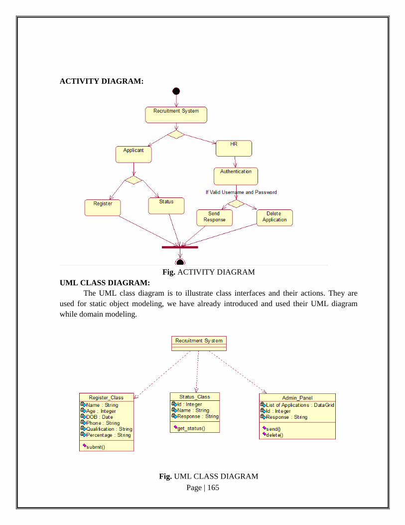
Page | 165
ACTIVITY DIAGRAM:
Fig. ACTIVITY DIAGRAM
UML CLASS DIAGRAM:
The UML class diagram is to illustrate class interfaces and their actions. They are
used for static object modeling, we have already introduced and used their UML diagram
while domain modeling.
Fig. UML CLASS DIAGRAM
Page | 166
UML SEQUENCE DIAGRAM:
A sequence diagram illustrates a kind of format in which each object interacts via message. It
is generalize between two or more specialized diagram.
POST- FUNCTION AND PRE-FUNCTION:
1. CANDIDATE REGISTRATION:
PRE-FUNCTION: Candidate should sign up by giving username and password.
POST-FUNCTION: Enter into the candidate information form, then candidate should enter
the personal details, qualification etc.
2. ACKNOWLEDGEMENT:
PRE-FUNCTION: Admin sends the reply to the candidate with register numbers.
POST-FUNCTION: Candidate could receive the mail from admin and get the register no.
3. LOGIN:
PRE-FUNCTION: Candidate should given the register no as user name and same password
which has already given while sign up his/her account
POST-FUNCTION: Enter into the software to attend the aptitude test. It will show the home
page.
4. APTITUDE TEST:
PRE-FUNCTION: Candidate should attend the test which is conducted on online.
POST-FUCTION: Submit the answer sheet to admin.
5. RESULT VERIFICATION:
PRE-FUNCTION: admin should correct the answer sheet which has been sent by
candidate.
POST-FUNCTION: Admin should select the candidate on the basis of his/her process and
send the report to concerned candidate (selected candidate).
6. UPDATE:
PRE-FUNCTION: Admin should update the admin tools and company details to
respective candidates.
POST-FUNCTION: Update are correctly views on the screen while user (candidate)browse
the particular webpage.
7. DIRECT HR INTERVIEW:
PRE-FUNCTION: Organization should check the certificates (if valid or not).
POST-FUNCTION: Direct questions are shooting out to the particular candidate.
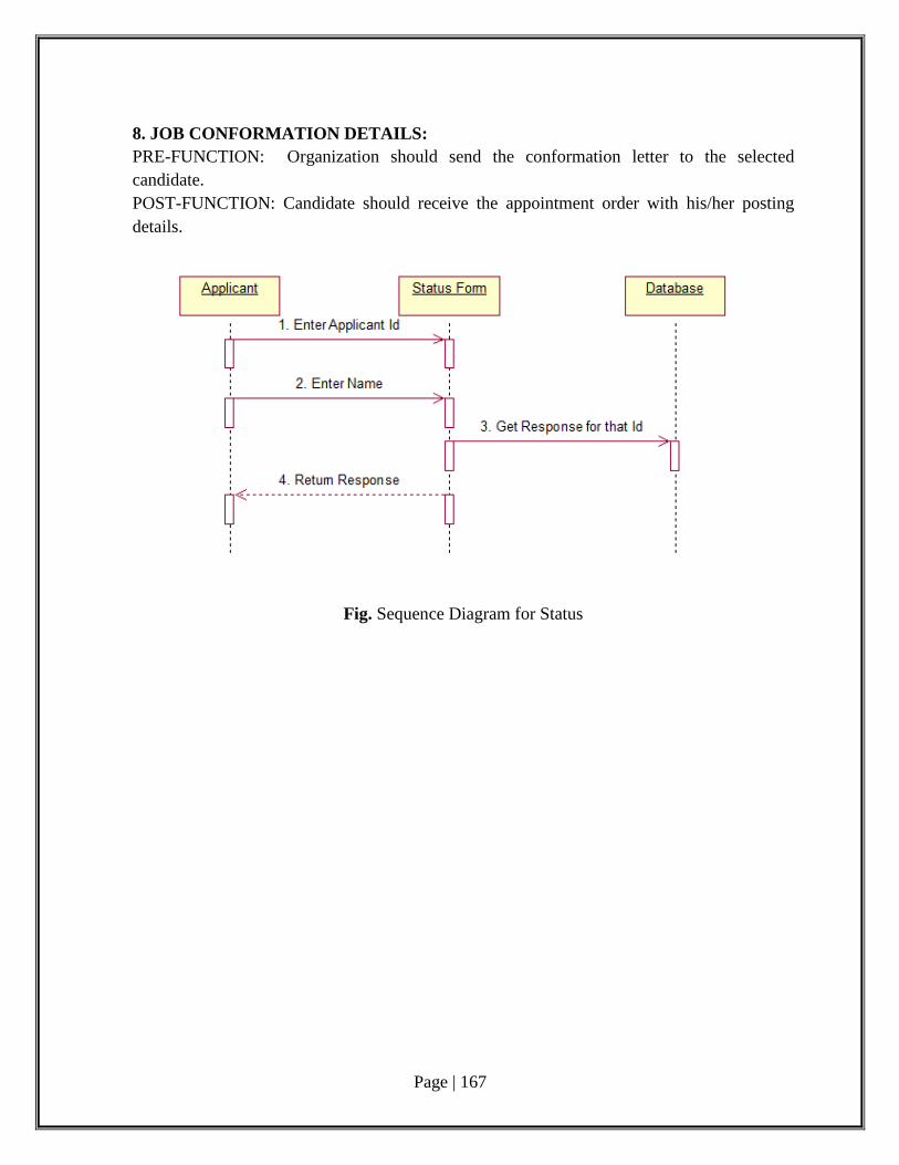
Page | 167
8. JOB CONFORMATION DETAILS:
PRE-FUNCTION: Organization should send the conformation letter to the selected
candidate.
POST-FUNCTION: Candidate should receive the appointment order with his/her posting
details.
Fig. Sequence Diagram for Status
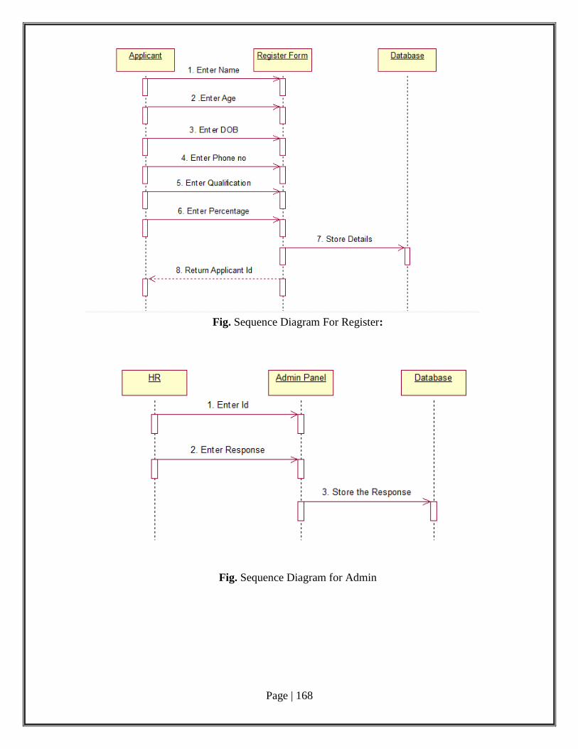
Page | 168
Fig. Sequence Diagram For Register:
Fig. Sequence Diagram for Admin
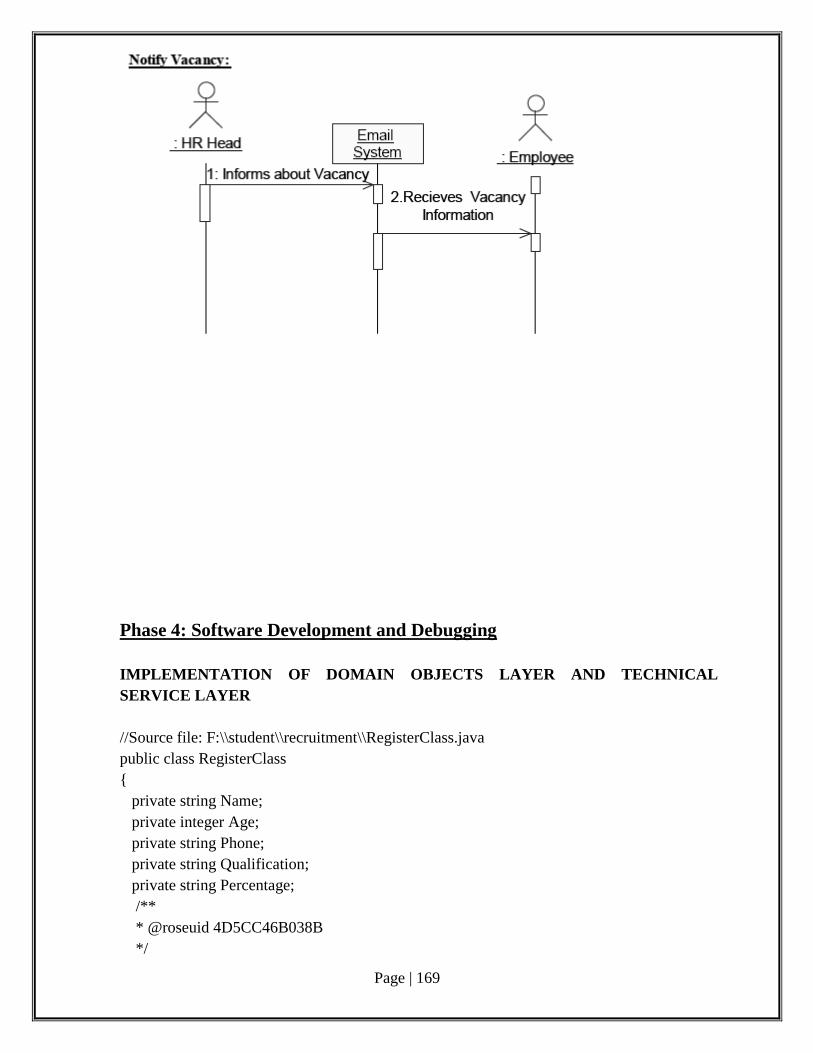
Page | 169
Phase 4: Software Development and Debugging
IMPLEMENTATION OF DOMAIN OBJECTS LAYER AND TECHNICAL
SERVICE LAYER
//Source file: F:\\student\\recruitment\\RegisterClass.java
public class RegisterClass
{
private string Name;
private integer Age;
private string Phone;
private string Qualification;
private string Percentage;
/**
* @roseuid 4D5CC46B038B
*/

Page | 170
public submit()
{
} }
//Source file: F:\\student\\recruitment\\Status_Class.java
public class Status_Class
{
private integer Id;
private string Name;
private string Response;
/**
* @roseuid 4D5CC46B038B
*/ public get_status() { }
}
Phase 5: Software Testing
Test cases:
A test case is a set of conditions or variables under which a tester will determine
whether a system under test satisfies requirements or works correctly.
Test Plan:
A test plan is a document detailing a systematic approach to testing a system such as a
machine or software. The plan typically contains a detailed understanding of the eventual
workflow.
Validation:
Validation checks that the product design satisfies or fits the intended use (high-level
checking), i.e., the software meets the user requirements. This is done through dynamic
testing and other forms of review.
Code coverage is a measure used to describe the degree to which the source code of a
program is tested by a particular test suite. A program with high code coverage has been
more thoroughly tested and has a lower chance of containing software bugs than a program
with low code coverage.
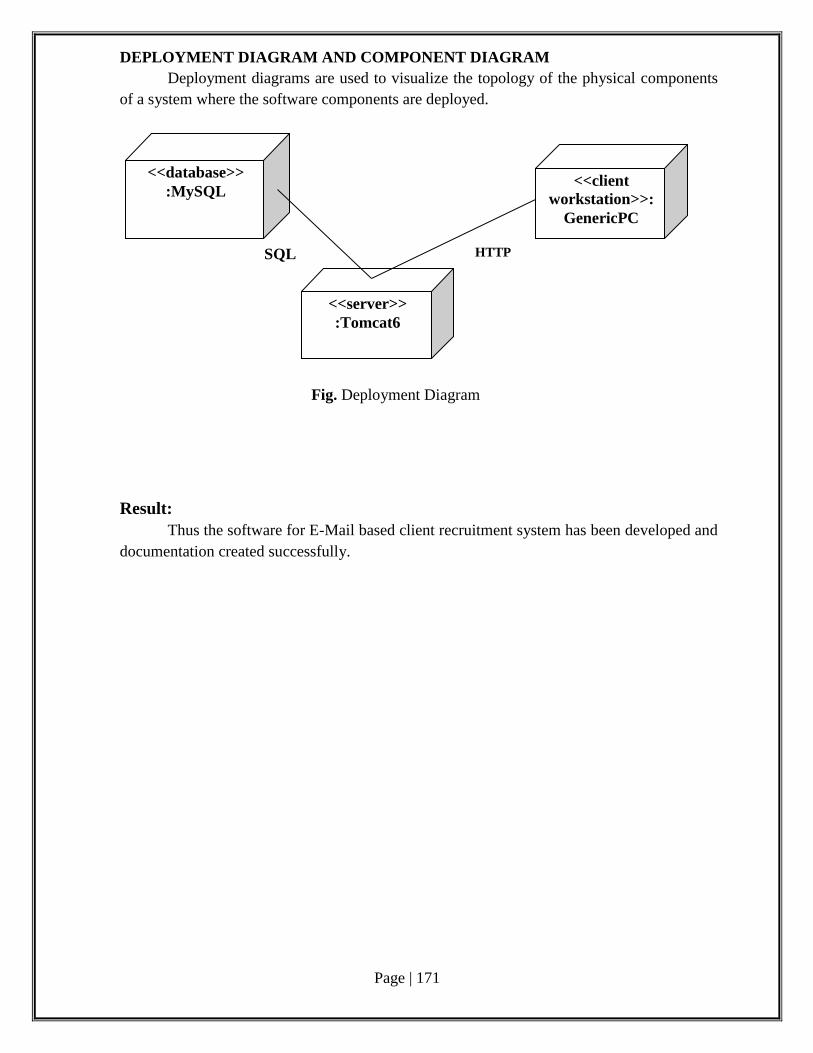
Page | 171
DEPLOYMENT DIAGRAM AND COMPONENT DIAGRAM
Deployment diagrams are used to visualize the topology of the physical components
of a system where the software components are deployed.
Fig. Deployment Diagram
Result:
Thus the software for E-Mail based client recruitment system has been developed and
documentation created successfully.
<<database>>
:MySQL <<client
workstation>>:
GenericPC
<<server>>
:Tomcat6
SQL HTTP
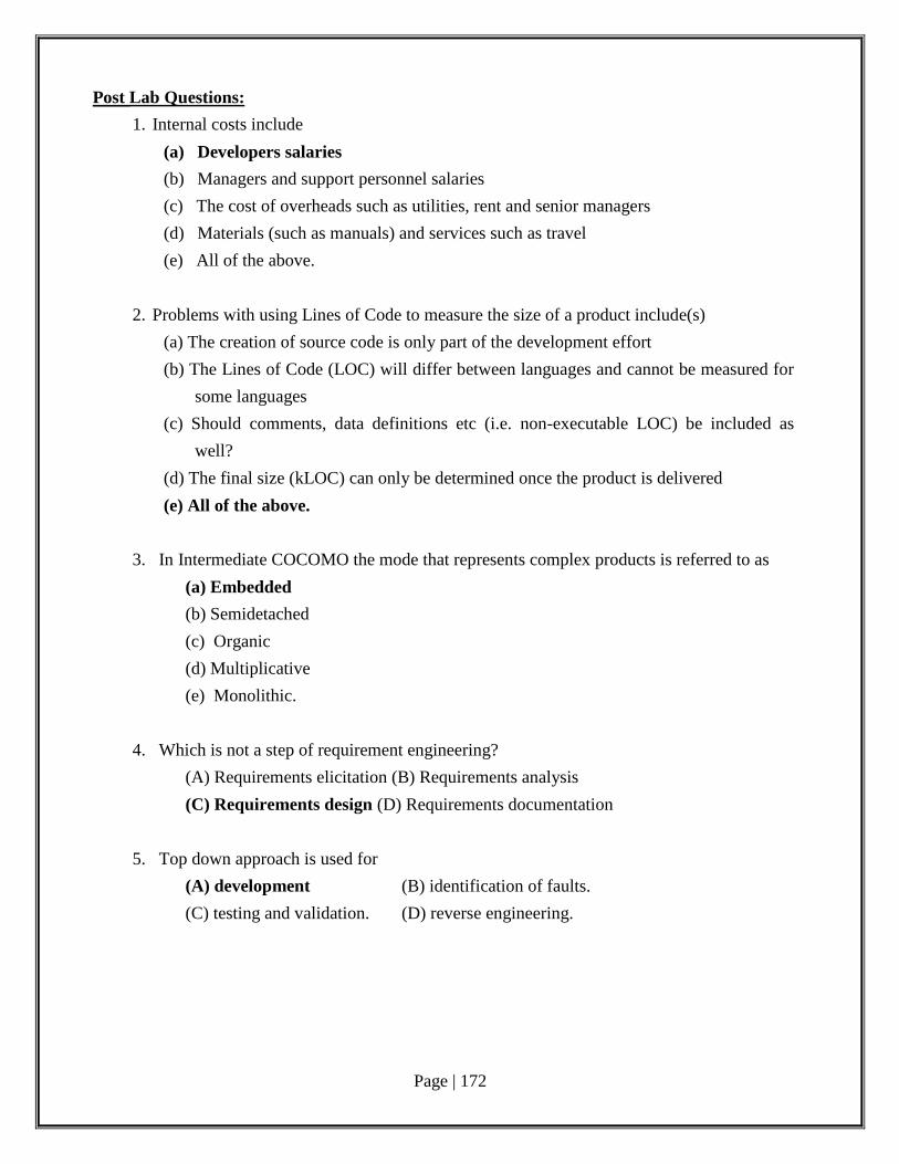
Page | 172
Post Lab Questions:
1. Internal costs include
(a) Developers salaries
(b) Managers and support personnel salaries
(c) The cost of overheads such as utilities, rent and senior managers
(d) Materials (such as manuals) and services such as travel
(e) All of the above.
2. Problems with using Lines of Code to measure the size of a product include(s)
(a) The creation of source code is only part of the development effort
(b) The Lines of Code (LOC) will differ between languages and cannot be measured for
some languages
(c) Should comments, data definitions etc (i.e. non-executable LOC) be included as
well?
(d) The final size (kLOC) can only be determined once the product is delivered
(e) All of the above.
3. In Intermediate COCOMO the mode that represents complex products is referred to as
(a) Embedded
(b) Semidetached
(c) Organic
(d) Multiplicative
(e) Monolithic.
4. Which is not a step of requirement engineering?
(A) Requirements elicitation (B) Requirements analysis
(C) Requirements design (D) Requirements documentation
5. Top down approach is used for
(A) development (B) identification of faults.
(C) testing and validation. (D) reverse engineering.