Embed Size (px)
Citation preview

EXOR International
www.exorint.net
Industrial Computing SolutionsFanless ComputereCC2200User Manual

Copyright © 2014 EXOR International S.p.A. All Rights Reserved. ii eCC2200 User Manual
Content
CONTENTS
PrefaceCopyright ............................................................................................. iv
Disclaimer .............................................................................................. iv
Acknowledgements ............................................................................... iv
Regulatory Compliance Statements ........................................................ iv
Declaration of Conformity ...................................................................... iv
RoHS Compliance ................................................................................... v
Warranty and RMA ................................................................................ vi
Safety Information ................................................................................viii
Installation Recommendations ...............................................................viii
Safety Precautions .................................................................................. ix
Technical Support and Assistance ............................................................ x
Conventions Used in this Manual ............................................................ x
Package Contents .................................................................................. xi
Ordering Information .............................................................................xii
Chapter 1: Product IntroductionOverview ................................................................................................1
Key Features ...........................................................................................1
Hardware Specifications ..........................................................................2
Knowing Your eCC2200 .........................................................................3
Mechanical Dimensions ...........................................................................5
eCC2200 .............................................................................................5
eCC2210/ eCC2210E ..........................................................................6
Chapter 2: Jumpers and ConnectorsBefore You Begin ....................................................................................7
Precautions ............................................................................................7
Jumper Settings ......................................................................................8
Locations of the Jumpers and Connectors for NISB 2200 .........................9
Jumpers ................................................................................................11
RTC Clear ..........................................................................................11
Panel CCFL Power Jump ....................................................................11
COM5 RS232 RI# Pin Power Select ....................................................12
COM6 RS232 RI# Pin Power Select ....................................................12
Connector Pin Definitions .....................................................................13
External I/O Interfaces – Front Panel ...................................................13
USB 2.0 ..........................................................................................13
COM1 and COM2 Connector ........................................................13
GPIO ..............................................................................................14
SIM Card Connector ......................................................................15
CFast Connector ............................................................................15
Audio Connectors ..........................................................................16
Power Switch .................................................................................16
LAN1/LAN2 Link/Active LEDs ..........................................................17
External I/O Interfaces – Rear Panel ....................................................18
9~36V DC Power Input ..................................................................18
DVI-I Connector .............................................................................18
HDMI .............................................................................................19
LAN1 and USB 2.0 Ports .................................................................19
LAN2 and USB 2.0 Ports .................................................................20

Copyright © 2014 EXOR International S.p.A. All Rights Reserved. iii eCC2200 User Manual
Content
COM5 and COM6 Ports .................................................................21
COM3 and COM4 Ports .................................................................22
Internal Connectors ...........................................................................23
LVDS Connector .............................................................................23
Panel CCFL Connector ...................................................................23
Mini-PCIe Connector ......................................................................24
3.5G Line-out Pin Header ...............................................................25
3.5G Mic Pin Header ......................................................................25
Line-in Pin Header ..........................................................................26
SATA1 Connector ...........................................................................26
SATA1 Power Connector ................................................................27
SATA2 Connector ...........................................................................27
SATA2 Power Connector ................................................................28
FAN1 Connector ............................................................................28
FAN2 Connector ............................................................................29
GPIO Pin Header ............................................................................29
GPS Connector ..............................................................................30
Print Box Header ............................................................................30
PWR_BT/RET_BT/LED Pin Header ....................................................31
SMBUS/LAN1/2 LED Pin Header ......................................................31
USB Internal Connector ..................................................................32
POE Connector ..............................................................................32
PCI Connector ................................................................................33
PCIe x4 ..........................................................................................35
Chapter 3: System SetupRemoving the Chassis Bottom Cover ....................................................36
Installing a SATA Hard Drive ..................................................................37
Installing a SATA Hard Drive for eCC2210/2210E ..................................39
Installing a SATA DOM ..........................................................................41
Remove the Chassis Top Cover ..............................................................43
Installing a SO-DIMM ............................................................................44
Installing a Wireless LAN Module (half-size) ...........................................45
Installing a 3.5G Module (full size) ........................................................46
Installing a GPS Module ........................................................................47
Installing Antenna .................................................................................49
Installing the SIM Card ..........................................................................51
Installing a CFast Card ..........................................................................52
Wallmount Brackets ..............................................................................53
Chapter 4: BIOS SetupAbout BIOS Setup .................................................................................54
When to Configure the BIOS .................................................................54
Default Configuration ...........................................................................55
Entering Setup ......................................................................................55
Legends ................................................................................................55
BIOS Setup Utility ..................................................................................57
Main .................................................................................................57
Advanced ..........................................................................................59
Chipset ..............................................................................................79
Boot ..................................................................................................87
Security .............................................................................................92
Save & Exit ........................................................................................92
Appendix A: GPI/O Programming Guide...............94
Appendix B: Watchdog Timer.................................95

Copyright © 2014 EXOR International S.p.A. All Rights Reserved. iv eCC2200 User Manual
Preface
PREFACE
Copyright This publication, including all photographs, illustrations and software, is
protected under international copyright laws, with all rights reserved. No
part of this manual may be reproduced, copied, translated or transmitted
in any form or by any means without the prior written consent from EXOR
International S.p.A.
DisclaimerThe information in this document is subject to change without prior notice and
does not represent commitment from EXOR International Co., Ltd. However,
users may update their knowledge of any product in use by constantly checking
its manual posted on our website: http://www.exorint.net. EXOR shall not be
liable for direct, indirect, special, incidental, or consequential damages arising
out of the use of any product, nor for any infringements upon the rights
of third parties, which may result from such use. Any implied warranties of
merchantability or fitness for any particular purpose is also disclaimed.
AcknowledgementseCC2200 is a trademark of EXOR International S.p.A. All other product
names mentioned herein are registered trademarks of their respective
owners.
Regulatory Compliance StatementsThis section provides the FCC compliance statement for Class B devices and
describes how to keep the system CE compliant.
Declaration of ConformityCE
The product(s) described in this manual complies with all applicable
European Union (CE) directives if it has a CE marking. For computer systems
to remain CE compliant, only CE-compliant parts may be used. Maintaining
CE compliance also requires proper cable and cabling techniques.

Copyright © 2014 EXOR International S.p.A. All Rights Reserved. v eCC2200 User Manual
Preface
RoHS ComplianceEXOR RoHS Environmental Policy and Status Update
This publication, including all photographs, illustrations
and software, is protected under international copyright
laws, with all rights reserved. No part of this manual
may be reproduced, copied, translated or transmitted in any form or by any
means without the prior written consent from EXOR International S.p.A.
RoHS restricts the use of Lead (Pb) < 0.1% or 1,000ppm, Mercury (Hg) < 0.1%
or 1,000ppm, Cadmium (Cd) < 0.01% or 100ppm, Hexavalent Chromium
(Cr6+) < 0.1% or 1,000ppm, Polybrominated biphenyls (PBB) < 0.1% or
1,000ppm, and Polybrominated diphenyl Ethers (PBDE) < 0.1% or 1,000ppm.
In order to meet the RoHS compliant directives, EXOR has established an
engineering and manufacturing task force to implement the introduction
of green products. The task force will ensure that we follow the standard
EXOR development procedure and that all the new RoHS components and
new manufacturing processes maintain the highest industry quality levels
for which EXOR are renowned.
The model selection criteria will be based on market demand. Vendors and
suppliers will ensure that all designed components will be RoHS compliant.
How to recognize EXOR RoHS Products?
For existing products where there are non-RoHS and RoHS versions, the
suffix “(LF)” will be added to the compliant product name.
All new product models launched after January 2006 will be RoHS compliant.
They will use the usual EXOR naming convention.

Copyright © 2014 EXOR International S.p.A. All Rights Reserved. vi eCC2200 User Manual
Preface
Warranty and RMAEXOR Warranty Period
EXOR manufactures products that are new or equivalent to new in
accordance with industry standard. EXOR warrants that products will be
free from defect in material and workmanship for 2 years, beginning on
the date of invoice by EXOR. HCP series products (Blade Server) which are
manufactured by EXOR are covered by a three year warranty period.
EXOR Return Merchandise Authorization (RMA)
▪ Customers shall enclose the “EXOR RMA Service Form” with the returned
packages.
▪ Customers must collect all the information about the problems
encountered and note anything abnormal or, print out any on-screen
messages, and describe the problems on the “EXOR RMA Service Form”
for the RMA number apply process.
▪ Customers can send back the faulty products with or without accessories
(manuals, cable, etc.) and any components from the card, such as CPU
and RAM. If the components were suspected as part of the problems,
please note clearly which components are included. Otherwise, EXOR is
not responsible for the devices/parts.
▪ Customers are responsible for the safe packaging of defective products,
making sure it is durable enough to be resistant against further damage
and deterioration during transportation. In case of damages occurred
during transportation, the repair is treated as “Out of Warranty.”
▪ Any products returned by EXOR to other locations besides the customers’
site will bear an extra charge and will be billed to the customer.
Repair Service Charges for Out-of-Warranty Products
EXOR will charge for out-of-warranty products in two categories, one is
basic diagnostic fee and another is component (product) fee.
Repair Service Charges for Out-of-Warranty Products
EXOR will charge for out-of-warranty products in two categories, one is
basic diagnostic fee and another is component (product) fee.
System Level
▪ Component fee: EXOR will only charge for main components such as
SMD chip, BGA chip, etc. Passive components will be repaired for free,
ex: resistor, capacitor.
▪ Items will be replaced with EXOR products if the original one cannot be
repaired. Ex: motherboard, power supply, etc.
▪ Replace with 3rd party products if needed.
▪ If RMA goods can not be repaired, EXOR will return it to the customer
without any charge.
Board Level
▪ Component fee: EXOR will only charge for main components, such as
SMD chip, BGA chip, etc. Passive components will be repaired for free,
ex: resistors, capacitors.
▪ If RMA goods can not be repaired, EXOR will return it to the customer
without any charge.

Copyright © 2014 EXOR International S.p.A. All Rights Reserved. vii eCC2200 User Manual
Preface
Warnings
Read and adhere to all warnings, cautions, and notices in this guide and
the documentation supplied with the chassis, power supply, and accessory
modules. If the instructions for the chassis and power supply are inconsistent
with these instructions or the instructions for accessory modules, contact
the supplier to find out how you can ensure that your computer meets
safety and regulatory requirements.
Cautions
Electrostatic discharge (ESD) can damage system components. Do the
described procedures only at an ESD workstation. If no such station is
available, you can provide some ESD protection by wearing an antistatic
wrist strap and attaching it to a metal part of the computer chassis.

Copyright © 2014 EXOR International S.p.A. All Rights Reserved. viii eCC2200 User Manual
Preface
Installation RecommendationsEnsure you have a stable, clean working environment. Dust and dirt can get
into components and cause a malfunction. Use containers to keep small
components separated.
Adequate lighting and proper tools can prevent you from accidentally
damaging the internal components. Most of the procedures that follow
require only a few simple tools, including the following:
▪ A Philips screwdriver
▪ A flat-tipped screwdriver
▪ A grounding strap
▪ An anti-static pad
Using your fingers can disconnect most of the connections. It is recommended
that you do not use needle-nose pliers to disconnect connections as these
can damage the soft metal or plastic parts of the connectors.
Safety InformationBefore installing and using the device, note the following precautions:
▪ Read all instructions carefully.
▪ Do not place the unit on an unstable surface, cart, or stand.
▪ Follow all warnings and cautions in this manual.
▪ When replacing parts, ensure that your service technician uses parts
specified by the manufacturer.
▪ Avoid using the system near water, in direct sunlight, or near a heating
device.
▪ The load of the system unit does not solely rely for support from the
rackmounts located on the sides. Firm support from the bottom is highly
necessary in order to provide balance stability.
▪ The computer is provided with a battery-powered real-time clock circuit.
There is a danger of explosion if battery is incorrectly replaced. Replace
only with the same or equivalent type recommended by the manufacturer.
Discard used batteries according to the manufacturer’s instructions.

Copyright © 2014 EXOR International S.p.A. All Rights Reserved. ix eCC2200 User Manual
Preface
Safety Precautions1. Read these safety instructions carefully.
2. Keep this User Manual for later reference.
3. Disconnect this equipment from any AC outlet before cleaning. Use a
damp cloth. Do not use liquid or spray detergents for cleaning.
4. For plug-in equipment, the power outlet socket must be located near the
equipment and must be easily accessible.
5. Keep this equipment away from humidity.
6. Put this equipment on a stable surface during installation. Dropping it or
letting it fall may cause damage.
7. The openings on the enclosure are for air convection to protect the
equipment from overheating. DO NOT COVER THE OPENINGS.
8. Make sure the voltage of the power source is correct before connecting
the equipment to the power outlet.
9. Place the power cord in a way so that people will not step on it. Do not
place anything on top of the power cord. Use a power cord that has been
approved for use with the product and that it matches the voltage and
current marked on the product’s electrical range label. The voltage and
current rating of the cord must be greater than the voltage and current
rating marked on the product.
10. All cautions and warnings on the equipment should be noted.
11. If the equipment is not used for a long time, disconnect it from the
power source to avoid damage by transient overvoltage.
12. Never pour any liquid into an opening. This may cause fire or electrical
shock.
13. Never open the equipment. For safety reasons, the equipment should be
opened only by qualified service personnel.
14. If one of the following situations arises, get the equipment checked by
service personnel:
a. The power cord or plug is damaged.
b. Liquid has penetrated into the equipment.
c. The equipment has been exposed to moisture.
d. The equipment does not work well, or you cannot get it to work
according to the user’s manual.
e. The equipment has been dropped and damaged.
f. The equipment has obvious signs of breakage.
15. Do not place heavy objects on the equipment.
16. The unit uses a three-wire ground cable which is equipped with a third
pin to ground the unit and prevent electric shock. Do not defeat the
purpose of this pin. If your outlet does not support this kind of plug,
contact your electrician to replace your obsolete outlet.
17. CAUTION: DANGER OF EXPLOSION IF BATTERY IS INCORRECTLY
REPLACED. REPLACE ONLY WITH THE SAME OR EQUIVALENT TYPE
RECOMMENDED BY THE MANUFACTURER. DISCARD USED BATTERIES
ACCORDING TO THE MANUFACTURER’S INSTRUCTIONS.

Copyright © 2014 EXOR International S.p.A. All Rights Reserved. x eCC2200 User Manual
Preface
Technical Support and Assistance1. For the most updated information of EXOR products, visit EXOR’s website
at www.exorint.net.
2. For technical issues that require contacting our technical support team or
sales representative, please have the following information ready before
calling:
– Product name and serial number
– Detailed information of the peripheral devices
– Detailed information of the installed software (operating system,
version, application software, etc.)
– A complete description of the problem
– The exact wordings of the error messages
Warning!
1. Handling the unit: carry the unit with both hands and handle it with care.
2. Maintenance: to keep the unit clean, use only approved cleaning products
or clean with a dry cloth.
3. CompactFlash: Turn off the unit’s power before inserting or removing a
CompactFlash storage card.
Conventions Used in this Manual
Warning:
Information about certain situations, which if not observed,
can cause personal injury. This will prevent injury to yourself
when performing a task.
UTUTUTUTUTUTIOIOUTUTIOIOIOIOIOIOIOUTUTIOION!N!N!N!UTUTIOIOUTUTUTUTUTCAUTUTCACACAUTUTUTIOCACACACAUTUTUTUTIOIOIOION!N!N!N!CA ION!N!N!N!N!N!N!N!N!N!CAUTION!CAUTION!Caution:
Information to avoid damaging components or losing data.
Note:
Provides additional information to complete a task easily.

Copyright © 2014 EXOR International S.p.A. All Rights Reserved. xi eCC2200 User Manual
Preface
Package ContentsBefore continuing, verify that the NISE 2200 package that you received is complete. Your package should have all the items listed in the following table.
Item Name Qty
1 Terminal Blocks 2P Phoenix Contact 1
2 (H)I Head Screw Long 2
3 Flat Head Screw Long 4

Copyright © 2014 EXOR International S.p.A. All Rights Reserved. xii eCC2200 User Manual
Preface
Ordering InformationThe following information below provides ordering information for eCC2200.
• Barebone
- eCC2200
Intel® Atom™ Dual Core D2550 Fanless System
- eCC2210
Intel® Atom™ Dual Core D2550 Fanless System with one PCI Expansion
- eCC2210E
Intel® Atom™ Dual Core D2550 Fanless System with one PCIe x1 Expansion or one PCIe x4 Expansion

Copyright © 2014 EXOR International S.p.A. All Rights Reserved. 1 eCC2200 User Manual
Chapter 1: Product Introduction
CHAPTER 1: PRODUCT INTRODUCTION
Key Features ▪ On-board Intel® Atom™ Dual Core D2550 processor 1.86 GHz
▪ Intel® 82801JIR ICH10 RAID
▪ 1x DVI-I & 1x HDMI display output
▪ Dual Intel® 82574IT GbE LAN ports; support WoL, teaming & PXE
▪ 6x COM (2x RS-232/422/485 w/ isolation protection)
Overview
▪ 4x GPI & 4x GPO
▪ 6x USB2.0; 1x external CFast socket; 1x SIM card socket
▪ 1x internal mini-PCIe with two antenna holes
▪ Support +9V to 36VDC Input; support ATX power mode

Copyright © 2014 EXOR International S.p.A. All Rights Reserved. 2 eCC2200 User Manual
Chapter 1: Product Introduction
Hardware SpecificationsCPU Support
▪ On-board Intel® Atom™ Dual Core D2550 processor, 1.86GHz, 1M L2 cache ▪ Intel® 82801JIR ICH10 RAID
Main Memory
▪ 2x DDR3 SO-DIMM socket, support up to 4G DDR3/ DDR3L 1066/1333/1600 SDRAM, with un-buffered and non-ECC
▪ Pre-installed 4G Industrial Grade Memory as the manufacture configuration for shipment
I/O Interface-Front
▪ ATX Power on/off switch ▪ HDD access/ power status LEDs ▪ 2x DB9, RS232/422/485 w/ 2.5KV isolation protection ▪ 2x USB2.0 ▪ 1x DB15, 4x GPI & 4x GPO ▪ 1x Mic-in & 1x Line out ▪ SIM card socket ▪ CFast socket ▪ 2x antenna holes
I/O Interface-Rear
▪ 1x 2-pin DC input, support +9 to 36V DC input ▪ 1x HDMI ▪ 1x DVI-I ▪ Dual Intel® 82574IT GbE LAN ports; support WoL, teaming and PXE ▪ 4x USB2.0 ▪ 2x DB9, RS232/422/485 ▪ 2x DB9, RS232 only
Device
▪ 1x 2.5” SATA HDD driver bay
▪ 1x External CFast socket ▪ 1x External SIM card socket ▪ 1x internal mini-PCIe socket
(Support optional WiFi or 3.5G wireless module, jumper free)
Power Requirements
▪ Support +9 to 36VDC input; support ATX power mode ▪ Optional 19V, 65W power adapter
Dimensions
▪ 195mm (W) x 200mm (D) x 65mm (H) (7.7” x 7.9” x 2.6”)
Construction
▪ Aluminum chassis with fanless design
Environment
▪ Operating temperature:Ambient with air flow: -20°C to 65°C
▪ Storage temperature: -30°C to 85°C ▪ Relative humidity: 10% to 93% (Non-condensing) ▪ Shock protection:
- HDD: 20G, half sine, 11ms, IEC60068-2-27 - CFast: 50G, half sine, 11ms, IEC60068-2-27
▪ Vibration protection w/ HDD condition - Random: 0.5Grms @ 5~500 Hz according to IEC60068-2-64 - Sinusoidal: 0.5Grms @ 5~500 Hz according to IEC60068-2-6
Certifications
▪ CE approval
OS Support List
▪ Windows XP 32-bit ▪ Windows 7 32-bit ▪ WinCE 7.0

Copyright © 2014 EXOR International S.p.A. All Rights Reserved. 3 eCC2200 User Manual
Chapter 1: Product Introduction
Knowing Your eCC2200
CFast
GPIO w/ 2.5KV
isolation protection
Antenna hole
Power/HDD/LAN LED
USB2.0 Ports
Two USB2.0 ports to connect the system with USB2.0/1.1 devices.
COM1 and COM2 RS232/RS422/RS485
Used to connect RS232/422/485 compatible serial devices (with 2.5 KV isolation protection).
GPIO
The GPIO connector supports 4 digital input and 4 digital output (with 2.5 KV isolation protection).
CFast
Used to insert a CFast card.
SIM Card
Used to insert a SIM card.
Antenna Hole
Empty antenna holes reserved for installing optional Mini-PCIe Wi-Fi module.
Line-out
Line-out jack to connect speakers or headphones.
Mic-in
Mic-in jack to connect microphones.
Power/HDD/LAN LED
Indicates the power status of the system, hard drive and LAN activity.
Front Panel
COM1&2: RS232/422/485
w/ 2.5KV isolation protection
SIM card Mic-in
USB 2.0 Line-out

Copyright © 2014 EXOR International S.p.A. All Rights Reserved. 4 eCC2200 User Manual
Chapter 1: Product Introduction
Rear Panel
9~36 DC Input
DVI-I
HDMI
LAN
9~36V DC Input
Used to plug a DC power cord.
DVI-I
Used to connect a digital LCD panel.
HDMI
Used to connect a high-definition display.
USB2.0 Ports
Four USB2.0 ports to connect the system with USB2.0/1.1 devices.
Gigabit LAN Ports
Dual Gigabit LAN ports to connect the system to a local area network.
COM5 and COM6 RS232
Used to connect RS232 compatible serial devices.
COM3 and COM4 RS232/RS422/RS485
Used to connect RS232/422/485 compatible serial devices.USB 2.0 COM5&6: RS232
COM3&4:
RS232/422/485

Copyright © 2014 EXOR International S.p.A. All Rights Reserved. 5 eCC2200 User Manual
Chapter 1: Product Introduction
Mechanical Dimensions
65.00
71.00
216.80
204.80
194.49
200.00
160.00
120.00
25.00
eCC2200

Copyright © 2014 EXOR International S.p.A. All Rights Reserved. 6 eCC2200 User Manual
Chapter 1: Product Introduction
195.00204.80216.80
90.00
96.00
25.00
120.00
160.00
200.0012.50
eCC2210/ eCC2210E

Copyright © 2014 EXOR International S.p.A. All Rights Reserved. 7 eCC2200 User Manual
Chapter 2: Jumpers and Connectors
CHAPTER 2: JUMPERS AND CONNECTORS
This chapter describes how to set the jumpers and connectors on the
eCC2200 motherboard.
Before You Begin ▪ Ensure you have a stable, clean working environment. Dust and dirt can
get into components and cause a malfunction. Use containers to keep
small components separated.
▪ Adequate lighting and proper tools can prevent you from accidentally
damaging the internal components. Most of the procedures that follow
require only a few simple tools, including the following:
– A Philips screwdriver
– A flat-tipped screwdriver
– A set of jewelers screwdrivers
– A grounding strap
– An anti-static pad
▪ Using your fingers can disconnect most of the connections. It is
recommended that you do not use needle-nosed pliers to disconnect
connections as these can damage the soft metal or plastic parts of the
connectors.
▪ Before working on internal components, make sure that the power is off.
Ground yourself before touching any internal components, by touching
a metal object. Static electricity can damage many of the electronic
components. Humid environments tend to have less static electricity than
dry environments. A grounding strap is warranted whenever danger of
static electricity exists.
Precautions Computer components and electronic circuit boards can be damaged by
discharges of static electricity. Working on computers that are still connected
to a power supply can be extremely dangerous.
Follow the guidelines below to avoid damage to your computer or yourself:
▪ Always disconnect the unit from the power outlet whenever you are
working inside the case.
▪ If possible, wear a grounded wrist strap when you are working inside the
computer case. Alternatively, discharge any static electricity by touching
the bare metal chassis of the unit case, or the bare metal body of any
other grounded appliance.
▪ Hold electronic circuit boards by the edges only. Do not touch the
components on the board unless it is necessary to do so. Don’t flex or
stress the circuit board.
▪ Leave all components inside the static-proof packaging that they shipped
with until they are ready for installation.
▪ Use correct screws and do not over tighten screws.

Copyright © 2014 EXOR International S.p.A. All Rights Reserved. 8 eCC2200 User Manual
Chapter 2: Jumpers and Connectors
Jumper SettingsA jumper is the simplest kind of electric switch. It consists of two metal
pins and a cap. When setting the jumpers, ensure that the jumper caps are
placed on the correct pins. When the jumper cap is placed on both pins, the
jumper is short. If you remove the jumper cap, or place the jumper cap on
just one pin, the jumper is open.
Refer to the illustrations below for examples of what the 2-pin and 3-pin
jumpers look like when they are short (on) and open (off).
Two-Pin Jumpers: Open (Left) and Short (Right)
Three-Pin Jumpers: Pins 1 and 2 are Short
12
3
12
3
Copyright © 2014 EXOR International S.p.A. All Rights Reserved. 9 eCC2200 User Manual
Chapter 2: Jumpers and Connectors
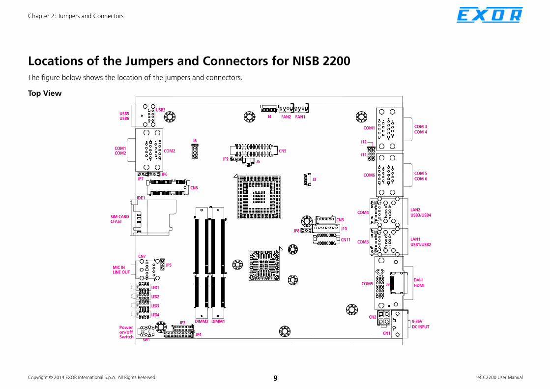
Locations of the Jumpers and Connectors for NISB 2200The figure below shows the location of the jumpers and connectors.
COM 3
COM 4
COM 5
COM 6
LAN2
USB3/USB4
LAN1
USB1/USB2
DVI-I
HDMI
9-36V
DC INPUT
J9COM5
COM3
COM4
COM6
COM1
J3
FAN1FAN2J4
CN5
J5JP2
J6
JP6
USB3
COM2
CN6
JP7
IDE1
COM1
COM2
SIM CARD
CFAST
JP5
JP3 DIMM1DIMM2
JP4
SW1
CN7
MIC IN
LINE OUT
Power
on/off
Switch
LED1
LED2
LED3
LED4
USB5
USB6
CN3
J10
CN11
JP8
J12
J11
CN2
CN1
Top View

Copyright © 2014 EXOR International S.p.A. All Rights Reserved. 10 eCC2200 User Manual
Chapter 2: Jumpers and Connectors
Bottom View
CN10
SATA2 SATA1
J7
J8
CN8CN9

Copyright © 2014 EXOR International S.p.A. All Rights Reserved. 11 eCC2200 User Manual
Chapter 2: Jumpers and Connectors
Jumpers
RTC ClearConnector type: 1x3 3-pin header, 2.54mm pitch
Connector location: JP2
Pin Settings
1-2 On Normal
2-3 On Clear BIOS
1-2 On: default
Panel CCFL Power JumpConnector type: 1x3 3-pin header, 2.54mm pitch
Connector location: JP8
Pin Definition
1 VCC3_S (3.3V)
2 VCC_LCD
3 VCC5_S(+5V)
1-2 On: default
1 3 1 3

Copyright © 2014 EXOR International S.p.A. All Rights Reserved. 12 eCC2200 User Manual
Chapter 2: Jumpers and Connectors
COM5 RS232 RI# Pin Power SelectConnector type: 1x5 5-pin header, 2.0mm pitch
Connector location: J11
Pin Definition
1 VCC5_S
2 SP5_RI_T
3 VCC12_S
4 SP5_RI_T
5 SP5_RI
Pin Settings
1-2 On +5V
2-3 On +12V
4-5 On RING
4-5 On: default
COM6 RS232 RI# Pin Power SelectConnector type: 1x5 5-pin header, 2.0mm pitch
Connector location: J12
Pin Definition
1 VCC5_S
2 SP6_RI_T
3 VCC12_S
4 SP6_RI_T
5 SP6_RI
Pin Settings
1-2 On +5V
2-3 On +12V
4-5 On RING
4-5 On: default
1 5 1 5

Copyright © 2014 EXOR International S.p.A. All Rights Reserved. 13 eCC2200 User Manual
Chapter 2: Jumpers and Connectors
Connector Pin Definitions
External I/O Interfaces – Front Panel
USB 2.0
Connector type: Dual USB port, Type A
Connector location: USB3
Pin Definition Pin Definition
1 VCC5_A 5 VCC5_A
2 USB_4N 6 USB_5N
3 USB_4P 7 USB_5P
4 GND 8 GND
COM1 and COM2 Connector
Connector type: DB-9 port
Connector location: COM2A (COM1) and COM2B (COM2)
RS232 RS485 RS422
Pin Definition Pin Definition Pin Definition
1 SP1_DCD 1 SP1_DATA- 1 SP1_TX-
2 SP1_RXD 2 SP1_DATA+ 2 SP1_TX+
3 SP1_TXD 3 NC 3 SP1_RX+
4 SP1_DTR 4 NC 4 SP1_RX-
5 ISO_GND 5 ISO_GND 5 ISO_GND
6 SP1_DSR 6 NC 6 SP1_RTS-
7 SP1_RTS 7 NC 7 SP1_RTS+
8 SP1_CTS 8 NC 8 SP1_CTS+
9 SP1_RI 9 NC 9 SP1_CTS-
COM1 Connector Pin Definition
1 56 9

Copyright © 2014 EXOR International S.p.A. All Rights Reserved. 14 eCC2200 User Manual
Chapter 2: Jumpers and Connectors
RS232 RS485 RS422
Pin Definition Pin Definition Pin Definition
1 SP2_DCD 1 SP2_DATA- 1 SP2_TX-
2 SP2_RXD 2 SP2_DATA+ 2 SP2_TX+
3 SP2_TXD 3 NC 3 SP2_RX+
4 SP2_DTR 4 NC 4 SP2_RX-
5 ISO_GND 5 ISO_GND 5 ISO_GND
6 SP2_DSR 6 NC 6 SP2_RTS-
7 SP2_RTS 7 NC 7 SP2_RTS+
8 SP2_CTS 8 NC 8 SP2_CTS+
9 SP2_RI 9 NC 9 SP2_CTS-
COM2 Connector Pin Definition GPIO
External connector type: DB-15, 2x5 10-pin header
1 5
6 10
Pin Definition Pin Definition
1 ISO_VCC5 6 ISO_GND
2 SIO_GPI20 7 SIO_GPO24
3 SIO_GPI21 8 SIO_GPO25
4 SIO_GPI22 9 SIO_GPO26
5 SIO_GPI23 10 SIO_GPO27
Pin Definition Pin Definition
1 ISO_VCC5 2 ISO_GND
3 SIO_GPO24 4 SIO_GPI20
5 SIO_GPO25 6 SIO_GPI21
7 SIO_GPO26 8 SIO_GPI22
9 SIO_GPO27 10 SIO_GPI23
1 9
2 10
Internal connector location: J6

Copyright © 2014 EXOR International S.p.A. All Rights Reserved. 15 eCC2200 User Manual
Chapter 2: Jumpers and Connectors
SIM Card Connector
Connector location: IDE1
C3
C2
C1
C7
C6
C5
Pin Definition Pin Definition
C1 UIM_PWR C2 UIM_RESET
C3 UIM_CLK C5 GND
C6 UIM_VPP C7 UIM_DATA
CFast Connector
Connector location: CN10
Pin Definition Pin Definition
S1 GND PC6 NC
S2 SATA_TXP1 PC7 GND
S3 SATA_TXN1 PC8 NC
S4 GND PC9 CFAST_ACCESS
S5 SATA_RXN1 PC10 NC
S6 SATA_RXP1 PC11 NC
S7 GND PC12 NC
PC1 CDI PC13 +3.3V
PC2 GND PC14 +3.3V
PC3 NC PC15 GND
PC4 NC PC16 GND
PC5 NC PC17 NC
S1 S7 PC1 PC17

Copyright © 2014 EXOR International S.p.A. All Rights Reserved. 16 eCC2200 User Manual
Chapter 2: Jumpers and Connectors
Audio Connectors
Connector type: 2x 3.5mm TRS
Connector location: CN7A (Mic-in) and CN7B (Line-out)
Pin Definition Pin Definition
1 NC 2 MIC_L
3 GND 4 MIC_JD
5 MIC_R
22 OUT_L 23 GND
24 EXLINEOUT_JD 25 OUT_R
NH1
Line-out
Mic-in
Power Switch
Connector location: SW1
Pin Definition Pin Definition
1 GND 2 VCC3_A
3 VCC3_A 4 GND
A1 PWRLED_N C1 PWRLED_P
MH1 NC MH2 NC

Copyright © 2014 EXOR International S.p.A. All Rights Reserved. 17 eCC2200 User Manual
Chapter 2: Jumpers and Connectors
LAN1 #1
LAN1/LAN2 Link/Active LEDs
Connector location: LED1 and LED2
#2
LAN2
LNK
ACT
LNK
ACT
#3 #4
PW
CFast
HDD1
HDD2
Status LED Color Definition
LAN1/LNK Green Link status of LAN1
LAN1/ACT Yellow Network activity of LAN1
LAN2/LNK Green Link status of LAN2
LAN2/ACT Yellow Network activity of LAN2
Status LED Color Definition
#1/RX Green Receive signal of COM1
#1/TX Yellow Transmit signal of COM1
#2/RX Green Receive signal of COM2
#2/TX Yellow Transmit signal of COM2
RX
TX
RX
TX
Status LED Color Definition
#3/RX Green Receive signal of COM3
#3/TX Yellow Transmit signal of COM3
#4/RX Green Receive signal of COM3
#4/TX Yellow Transmit signal of COM4
Status LED Color Definition
PW Green Power status of the system
CFast Yellow Activity of CFast
HDD1 Yellow Activity of HDD1
HDD2 Yellow Activity of HDD2
LAN Ports
COM1 and COM2
COM3 and COM4
Power, CFast, HDD1 and HDD2
Note: LED indication of NISE2200/NISE2300 is controlled by HDD/SSD/CFast itself. Some
HDD/SSD/CFast might not flash due to its design limitation.
FlashingLED
On
No
LED
SSD
Apacer SSD APS25P6B032G-CCM 32G ü
Apacer SSD APS25P6B032G-CTW 32G ü
Apacer SSD APS25P6B064G-CCM 64G ü
2.5
” HD
D
2.5” HDD Toshiba MK1676GSX 160G ü
2.5” HDD Hitachi HTS541640J9SA00 40G ü
2.5" HDD Seagate ST9160314AS 160G ü
2.5" HDD Fujitsu MHZ008DBH 80G ü
Cfa
st
Cfast Transcend 8G ü
Cfast Apacer APCFA004GT6HS-ETT 4G ü
Cfast Unigen UGB31JAC8000A1 8G ü

Copyright © 2014 EXOR International S.p.A. All Rights Reserved. 18 eCC2200 User Manual
Chapter 2: Jumpers and Connectors
External I/O Interfaces – Rear Panel
9~36V DC Power Input
Connector type: Phoenix Contact 1x2 2-pin terminal block
Connector location: CN1
Pin Definition
1 GND
2 VIN
DVI-I Connector
Connector type: 24-pin D-Sub, 2.0mm-M-180 (DVI)
Connector location: CON5
Pin Definition Pin Definition
1 TX2- 2 TX2+
3 GND 4 NC
5 NC 6 DDC_CLK
7 DDC_DATA 8 VSYNC_VGA
9 TX1- 10 TX1+
11 GND 12 NC
13 NC 14 DVI_VCC(+5V)
15 GND 16 HotPlugDet
17 TX0- 18 TX0+
19 GND 20 DDCCLK_VGA
21 DDCDATA_VGA 22 GND
23 TXCLK+ 24 TXCLK-
1
17 24
8

Copyright © 2014 EXOR International S.p.A. All Rights Reserved. 19 eCC2200 User Manual
Chapter 2: Jumpers and Connectors
HDMI
Connector type: HDMI port
Connector location: J9
Pin Definition Pin Definition
1 HDMI_DATA2_P 2 GND
3 HDMI_DATA2_N 4 HDMI_DATA1_P
5 GND 6 HDMI_DATA1_N
7 HDMI_DATA0_P 8 GND
9 HDMI_DATA0_N 10 HDMI_CLK_P
11 GND 12 HDMI_CLK_N
13 NC 14 NC
15 HDMI_CTRL_CLK 16 HDMI_CTRL_DATA
17 GND 18 HDMI_VCC5
19 HDMI_HPD_R 20
LAN1 and USB 2.0 Ports
Connector type: RJ45 port with LEDs and dual USB 2.0 ports
Connector location: CON3B (LAN1) and CON3A (USB1/2)
ACT LINK
Pin Definition Pin Definition
1 VCC5A 5 VCC5A
2 USB_0N 6 USB_1N
3 USB_0P 7 USB_1P
4 GND 8 GND
Link Status
Steady Green 1G network link
Steady Orange 10/100Mbps network link
Off No link
Act Status
Flashing Yellow Data activity
Off No activity
USB1/2
1
1
5
4
1017
8
219
18

Copyright © 2014 EXOR International S.p.A. All Rights Reserved. 20 eCC2200 User Manual
Chapter 2: Jumpers and Connectors
Pin Definition Pin Definition
9 LAN3P1V9 18 GND
10 LAN3_MDI0P 19 LAN3_LED3P
11 LAN3_MDI0N 20 LAN3_LED2P
12 LAN3_MDI1P 21 LAN3_LED_ACT#
13 LAN3_MDI1N 22 LAN3_LED1P
14 LAN3_MDI2P MH5 GND
15 LAN3_MDI2N MH6 GND
16 LAN3_MDI3P MH7 GND
17 LAN3_MDI3N MH8 GND
LAN1 LAN2 and USB 2.0 Ports
Connector type: RJ45 port with LEDs and dual USB 2.0 ports
Connector location: CON4B (LAN2) and CON4A (USB3/4)
Pin Definition Pin Definition
1 VCC5A 5 VCC5A
2 USB_2N 6 USB_3N
3 USB_2P 7 USB_3P
4 GND 8 GND
Link Status
Steady Green 1G network link
Steady Orange 10/100Mbps network link
Off No link
Act Status
Flashing Yellow Data activity
Off No activity
USB3/4
ACT LINK
1
5
4
1017
8

Copyright © 2014 EXOR International S.p.A. All Rights Reserved. 21 eCC2200 User Manual
Chapter 2: Jumpers and Connectors
COM5 and COM6 Ports
Connector type: DB-9 port, 9-pin D-Sub
Connector location: COM6A (COM5) and COM6B (COM6)
Pin Definition Pin Definition
1 SP5_DCD 2 SP5_RXD
3 SP5_TXD 4 SP5_DTR
5 GND 6 SP5_DSR
7 SP5_RTS 8 SP5_CTS
9 SP5_RI
COM 5
COM5 Connector Pin Definition
Pin Definition Pin Definition
10 SP6_DCD 11 SP6_RXD
12 SP6_TXD 13 SP6_DTR
14 GND 15 SP6_DSR
16 SP6_RTS 17 SP6_CTS
18 SP6_RI
COM6 Connector Pin Definition
Pin Definition Pin Definition
9 LAN4P1V9 18 GND
10 LAN4_MDI0P 19 LAN4_LED3P
11 LAN4_MDI0N 20 LAN4_LED2P
12 LAN4_MDI1P 21 LAN4_LED_ACT#
13 LAN4_MDI1N 22 LAN4_LED1P
14 LAN4_MDI2P MH5 GND
15 LAN4_MDI2N MH6 GND
16 LAN3_MDI3P MH7 GND
17 LAN3_MDI3N MH8 GND
LAN2
1 56 9
COM 6
10 1415 18

Copyright © 2014 EXOR International S.p.A. All Rights Reserved. 22 eCC2200 User Manual
Chapter 2: Jumpers and Connectors
COM3 and COM4 Ports
Connector type: DB-9 port, 9-pin D-Sub
Connector location: COM1A (COM3) and COM1B (COM4)
COM3 Connector Pin Definition
RS232 RS485 RS422
Pin Definition Pin Definition Pin Definition
1 SP3_DCD 1 SP3_DATA- 1 SP3_TX-
2 SP3_RXD 2 SP3_DATA+ 2 SP3_TX+
3 SP3_TXD 3 NC 3 SP3_RX+
4 SP3_DTR 4 NC 4 SP3_RX-
5 GND 5 GND 5 GND
6 SP3_DSR 6 NC 6 SP3_RTS-
7 SP3_RTS 7 NC 7 SP3_RTS+
8 SP3_CTS 8 NC 8 SP3_CTS+
9 SP3_RI 9 NC 9 SP3_CTS-
RS232 RS485 RS422
Pin Definition Pin Definition Pin Definition
1 SP4_DCD 1 SP4_DATA- 1 SP4_TX-
2 SP4_RXD 2 SP4_DATA+ 2 SP4_TX+
3 SP4_TXD 3 NC 3 SP4_RX+
4 SP4_DTR 4 NC 4 SP4_RX-
5 GND 5 GND 5 GND
6 SP4_DSR 6 NC 6 SP4_RTS-
7 SP4_RTS 7 NC 7 SP4_RTS+
8 SP4_CTS 8 NC 8 SP4_CTS+
9 SP4_RI 9 NC 9 SP4_CTS-
COM4 Connector Pin Definition
COM 3
1 56 9
COM 4
1 56 9

Copyright © 2014 EXOR International S.p.A. All Rights Reserved. 23 eCC2200 User Manual
Chapter 2: Jumpers and Connectors
Internal Connectors
LVDS Connector
Connector type: 2x10 20-pin header, 1.25mm pitch
Connector location: CN11
Pin Definition Pin Definition
1 LVDS_DDC_CLK 2 LVDS_DDC_DAT
3 VCC_LCD(5V or 3.3V) 4 LVDS_TX0_DP
5 LVDS_TX3_DP 6 LVDS_TX0_DN
7 LVDS_TX3_DN 8 VCC_LCD(5V or 3.3V)
9 GND 10 LVDS_TX1_DP
11 LVDS_CLKP 12 LVDS_TX1_DN
13 LVDS_CLKN 14 GND
15 GND 16 V_INV (12V)
17 LVDS_TX2_DP 18 V_INV (12V)
19 LVDS_TX2_DN 20 GND
1 19
2 20
Panel CCFL Connector
Connector type: 1x7 JST, 7-pin header, 2.5mm pitch
Connector location: J10
7 1
Pin Definition
1 VCC_LCD
2 V_INV (12V)
3 V_INV (12V)
4 BKLTCTRL
5 GND
6 GND
7 BKLTEN

Copyright © 2014 EXOR International S.p.A. All Rights Reserved. 24 eCC2200 User Manual
Chapter 2: Jumpers and Connectors
1 2
51 52
Pin Definition Pin Definition
1 PCIEWAKE# 14 N/A
2 +3VSB 15 GND
3 N/A 16 N/A
4 GND 17 N/A
5 N/A 18 GND
6 +1.5V 19 N/A
7 CLKREQ# 20 Disable#
8 N/A 21 GND
9 GND 22 RST#
10 N/A 23 PCIERX0-
11 REF CLK- 24 +3VSB
12 N/A 25 PCIERX0+
13 REF CLK+ 26 GND
Mini-PCIe Connector
Connector location: CN6
Pin Definition Pin Definition
27 GND 40 GND
28 +1.5V 41 +3VSB
29 GND 42 N/A
30 SMBCLK 43 GND
31 PCIETX0- 44 N/A
32 SMBDATA 45 N/A
33 PCIETX0+ 46 N/A
34 GND 47 N/A
35 GND 48 +1.5V
36 USB_D- 49 N/A
37 GND 50 GND
38 USB_D+ 51 N/A
39 +3VSB 52 +3VSB

Copyright © 2014 EXOR International S.p.A. All Rights Reserved. 25 eCC2200 User Manual
Chapter 2: Jumpers and Connectors
3.5G Line-out Pin Header
Connector type: 1x3 3-pin header, 2.54mm pitch
Connector location: JP6
Pin Definition
1 LOUT_RL
2 LOUT_RR
3 ANGND
1 3
3.5G Mic Pin Header
Connector type: 1x3 3-pin header, 2.54mm pitch
Connector location: JP7
Pin Definition
1 MIC_RL
2 MIC_RR
3 ANGND
1 3

Copyright © 2014 EXOR International S.p.A. All Rights Reserved. 26 eCC2200 User Manual
Chapter 2: Jumpers and Connectors
Line-in Pin Header
Connector type: 1x4 4-pin header, 2.0mm pitch
Connector location: JP5
Pin Definition
1 FLIN_L
2 LIN_JD
3 GND
4 FLIN_R
1 4
SATA1 Connector
Connector type: Standard Serial ATAII 7P (1.27mm, SATA-M-180)
Connector location: SATA1
1 7
Pin Definition Pin Definition
1 GND 2 SATA_TXP0
3 SATA_TXN0 4 GND
5 SATA_RXN0 6 SATA_RXP0
7 DATA_DET0
Copyright © 2014 EXOR International S.p.A. All Rights Reserved. 27 eCC2200 User Manual
Chapter 2: Jumpers and Connectors
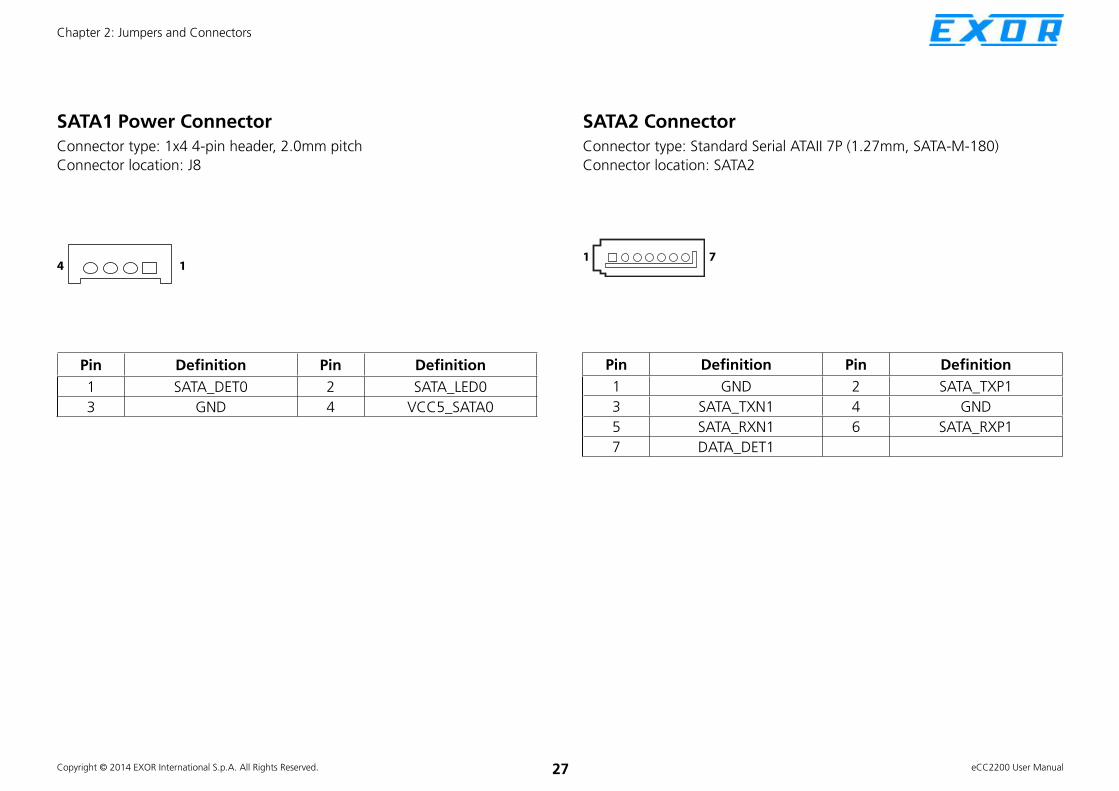
SATA1 Power Connector
Connector type: 1x4 4-pin header, 2.0mm pitch
Connector location: J8
Pin Definition Pin Definition
1 SATA_DET0 2 SATA_LED0
3 GND 4 VCC5_SATA0
14
SATA2 Connector
Connector type: Standard Serial ATAII 7P (1.27mm, SATA-M-180)
Connector location: SATA2
1 7
Pin Definition Pin Definition
1 GND 2 SATA_TXP1
3 SATA_TXN1 4 GND
5 SATA_RXN1 6 SATA_RXP1
7 DATA_DET1

Copyright © 2014 EXOR International S.p.A. All Rights Reserved. 28 eCC2200 User Manual
Chapter 2: Jumpers and Connectors
SATA2 Power Connector
Connector type: 1x4 4-pin header, 2.0mm pitch
Connector location: J7
Pin Definition Pin Definition
1 SATA_DET1 2 SATA_LED1
3 GND 4 VCC5_SATA1
14
FAN1 Connector
Connector type: 1x4 4-pin Wafer, 2.54mm pitch
Connector location: FAN1
Pin Definition Pin Definition
1 GND 3 FAN_TAC1 (CPU_FAN_SPEED)
2 VCC12_S 4 FAN_CTL1 (CPU_FAN_PWM)
1 4

Copyright © 2014 EXOR International S.p.A. All Rights Reserved. 29 eCC2200 User Manual
Chapter 2: Jumpers and Connectors
FAN2 Connector
Connector type: 1x4 4-pin Wafer, 2.54mm pitch
Connector location: FAN2
Pin Definition Pin Definition
1 GND 3 FAN_TAC2 (CPU_FAN_SPEED)
2 VCC12_S 4 FAN_CTL2 (CPU_FAN_PWM)
1 4
GPIO Pin Header
Connector type: 2x5 10-pin header, 2.0mm pitch
Connector location: J6
1 9
2 10
Pin Definition Pin Definition
1 ISO_VCC5 2 ISO_GND
3 SIO_GPO24(Pin58) 4 SIO_GPI20(Pin52)
5 SIO_GPO25(Pin59) 6 SIO_GPI21(Pin54)
7 SIO_GPO26(Pin60) 8 SIO_GPI22(Pin56)
9 SIO_GPO27(Pin61) 10 SIO_GPI23(Pin57)

Copyright © 2014 EXOR International S.p.A. All Rights Reserved. 30 eCC2200 User Manual
Chapter 2: Jumpers and Connectors
GPS Connector
Connector type: 1x6 JST, 6-pin header, 1.0mm pitch
Connector location: J3
1 6
Pin Definition Pin Definition
1 VCC3_A 2 NA
3 COM5_TXD 4 COM5_RXD
5 GND 6 VCC3_S
Print Box Header
Connector type: 2x13 26-pin header, 2.0mm pitch
Connector location: CN5
Pin Definition Pin Definition
1 LPT_RP_STB# 2 LPT_RP_PRD0
3 LPT_RP_PRD1 4 LPT_RP_PRD2
5 LPT_RP_PRD3 6 LPT_RP_PRD4
7 LPT_RP_PRD5 8 LPT_RP_PRD6
9 LPT_RP_PRD7 10 LPT_ACK#R
11 LPT_BUSY 12 LPT_PE
13 LPT_SLCT 14 LPT_AFD#R
15 LPT_ERR# 16 LPT_INIT#R
17 LPT_SLIN#R 18 LPT_GND
19 LPT_GND 20 LPT_GND
21 LPT_GND 22 LPT_GND
23 LPT_GND 24 LPT_GND
25 LPT_GND 26 NC
1
14
13
26

Copyright © 2014 EXOR International S.p.A. All Rights Reserved. 31 eCC2200 User Manual
Chapter 2: Jumpers and Connectors
PWR_BT/RET_BT/LED Pin Header
Connector type: 2x8 16-pin header, 2.0mm pitch
Connector location: JP3
Pin Definition Pin Definition
1 PWR_LED_N 2 PWR_LED_P
3 CFAST_ACCESS 4 SATA_LED_P
5 SATA_LED0_N 6 VCC5_S
7 SATA_LED1_N 8 VCC5_S
9 SLP_S3 10 PSON
11 RESET BOTTOM 12 GND
13 POWER BOTTOM 14 GND
15 AT Mode 16 GND
1 15
2 16
SMBUS/LAN1/2 LED Pin Header
Connector type: 2x10 20-pin header, 2.0mm pitch
Connector location: JP4
Pin Definition Pin Definition
1 SMBCLK 2 SMBDAT
3 VCC3_A 4 GND
5 NC 6 VCC3_A
7 NC 8 VCC3_A
9 NC 10 VCC3_A
11 NC 12 VCC3_A
13 LAN3LINKMIX 14 VCC3_A
15 LAN3_LED_ACT# 16 VCC3_A
17 LAN4LINKMIX 18 VCC3_A
19 LAN4_LED_ACT# 20 VCC3_A
1 19
2 20

Copyright © 2014 EXOR International S.p.A. All Rights Reserved. 32 eCC2200 User Manual
Chapter 2: Jumpers and Connectors
USB Internal Connector
Connector type: 1x6 JST, 6-pin header, 2.0mm pitch
Connector location: CN3
1 6
POE Connector
Connector type: 2x2 4-pin header, 4.2mm pitch
Connector location: CN2
1 2
3 4
Pin Definition Pin Definition
1 VCC5_A 2 USB_10N
3 USB_10P 4 USB_11N
5 USB_11P 6 GND
Pin Definition Pin Definition
1 GND 2 GND
3 VIN 4 VIN

Copyright © 2014 EXOR International S.p.A. All Rights Reserved. 33 eCC2200 User Manual
Chapter 2: Jumpers and Connectors
PCI Connector
Connector location: CN8
Pin Definition Pin Definition
A1 TRST# B1 -12V
A2 +12V B2 TCK
A3 TMS B3 GND
A4 TDI B4 TDO
A5 +5V B5 +5V
A6 INTA# B6 +5V
A7 INTC# B7 INTB#
A8 +5V B8 INTD#
A9 RSV1 B9 PRSNT1#
A10 +5V B10 RSV5
A11 RSV2 B11 PRSNT2#
A12 GND B12 GND
A13 GND B13 GND
A14 +3.3Vaux B14 RSV6
A15 RST# B15 GRPIMD
A16 +5V B16 CLK
A17 GNT# B17 GND
Pin Definition Pin Definition
A18 GND B18 REQ#
A19 PME# B19 +5V
A20 AD30 B20 AD31
A21 +3.3V B21 AD29
A22 AD28 B22 GND
A23 AD26 B23 AD27
A24 GND B24 AD25
A25 AD24 B25 +3.3V
A26 IDSEL B26 C/BE3#
A27 +3.3V B27 AD23
A28 AD22 B28 GND
A29 AD20 B29 AD21
A30 GND B30 AD19
A31 AD18 B31 +3.3V
A32 AD16 B32 AD17
A33 +3.3V B33 C/BE2#
A34 FRAME# B34 GND
A1 A62
B62B1

Copyright © 2014 EXOR International S.p.A. All Rights Reserved. 34 eCC2200 User Manual
Chapter 2: Jumpers and Connectors
Pin Definition Pin Definition
A35 GND B35 IRDY#
A36 TRDY# B36 +3.3V
A37 GND B37 DEVSEL#
A38 STOP# B38 GND
A39 +3.3V B39 LOCK#
A40 SMBCLK B40 PERR#
A41 SMBDAT B41 +3.3V
A42 GND B42 SERR#
A43 PAR B43 +3.3V
A44 AD15 B44 C/BE1#
A45 +3.3V B45 AD14
A46 AD13 B46 GND
A47 AD11 B47 AD12
A48 GND B48 AD10
A49 AD9 B49 GND
Connector Key
A52 C/BE0# B52 AD8
A53 +3.3V B53 AD7
A54 AD6 B54 +3.3V
A55 AD4 B55 AD5
A56 GND B56 AD3
A57 AD2 B57 GND
A58 AD0 B58 AD1
A59 +5V B59 +5V
A60 REQ64# B60 ACK64#
A61 +5V B61 +5V
A62 +5V B62 +5V

Copyright © 2014 EXOR International S.p.A. All Rights Reserved. 35 eCC2200 User Manual
Chapter 2: Jumpers and Connectors
PCIe x4
Connector location: CN9
Pin Definition Pin Definition
A1 PRSNT1 B1 VCC12_S
A2 VCC12_S B2 VCC12_S
A3 VCC12_S B3 VCC12_S
A4 GND B4 GND
A5 NC B5 SMBCLK
A6 NC B6 SMBDATA
A7 NC B7 GND
A8 NC B8 VCC3_S
A9 VCC3_S B9 NC
A0 VCC3_S B10 VCC3_A
A11 PLTRST#_A B11 PCIE_WAKE#
A12 GND B12 NC
A13 CLK_PCIE4_P B13 GND
A14 CLK_PCIE4_N B14 PE_TX1_P
A15 GND B15 PE_TX1_N
A16 PE_RX1_P B16 GND
Pin Definition Pin Definition
A17 PE_RX1_N B17 NC
A18 GND B18 GND
A19 RSVD3 B19 PE_TX2_P
A20 GND B20 PE_TX2_N
A21 PE_RX2_P B21 GND
A22 PE_RX2_N B22 GND
A23 GND B23 PE_TX3_P
A24 GND B24 PE_TX3_N
A25 PE_RX3_P B25 GND
A26 PE_RX3_N B26 GND
A27 GND B27 PE_TX4_P
A28 GND B28 PE_TX4_N
A29 PE_RX4_P B29 GND
A30 PE_RX4_N B30 RSVD2
A31 GND B31 PCIE4DET#
A32 RSVD4 B32 GND
A1 A32
B32B1

Copyright © 2014 EXOR International S.p.A. All Rights Reserved. 36 eCC2200 User Manual
Chapter 3: System Setup
CHAPTER 3: SYSTEM SETUP
Removing the Chassis Bottom Cover Note: Installation for SATA Hard Drive and SATA DOM only
UTUTUTUTUTUTIOIOIOIOIOIOIOIOIOIOUTUTUTIOIOION!N!N!N!UTUTUTIOIOIOUTUTUTUTUTUTUTCAUTUTCACACACAUTUTUTUTIOCACACACAUTUTUTUTIOIOIOION!N!N!N!CA ION!N!N!N!N!N!N!N!N!CAUTION!CAUTION!Prior to removing the chassis cover, make sure the unit’s power
is off and disconnected from the power sources to prevent
electric shock or system damage.
1. With the bottom side of the chassis facing up, remove the mounting screw of the bottom cover and then put them in a safe place for later use.
2. Lift up the cover and remove it from the chassis.

Copyright © 2014 EXOR International S.p.A. All Rights Reserved. 37 eCC2200 User Manual
Chapter 3: System Setup
Installing a SATA Hard DriveNote: The installation of SATA cable and SATA power cable must
follow the following pairs.
SATA drive/bracket
1. Remove 4 screws around the empty HDD bracket.
2. Use the provided screws to secure the drive in place.
3. Connect the SATA data/power cable and secure the cable with provided screws.
SATA data/power cable
Screw
Screw
Screw
Pair 1
Pair 2

Copyright © 2014 EXOR International S.p.A. All Rights Reserved. 38 eCC2200 User Manual
Chapter 3: System Setup
4. Connect the SATA data/power cable to the system according to the pairing model mentioned in the previous page.
5. Secure the HDD bracket to its original place.
SATA data/power cable

Copyright © 2014 EXOR International S.p.A. All Rights Reserved. 39 eCC2200 User Manual
Chapter 3: System Setup
1. Remove 4 screws around the empty HDD bracket.
2. Use the provided screws to secure the drive in place.Installing a SATA Hard Drive NOTE: Installation for eCC2210/2210E
Screw to fasten HDD drive
(both sides)
Copyright © 2014 EXOR International S.p.A. All Rights Reserved. 40 eCC2200 User Manual
Chapter 3: System Setup
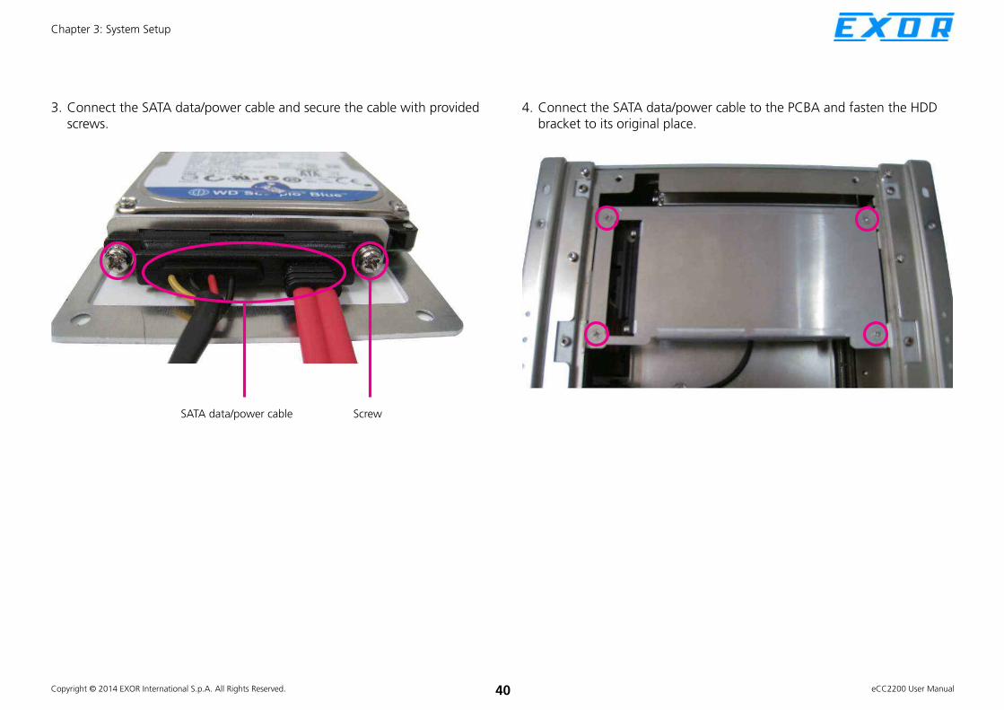
4. Connect the SATA data/power cable to the PCBA and fasten the HDD bracket to its original place.
3. Connect the SATA data/power cable and secure the cable with provided screws.
ScrewSATA data/power cable

Copyright © 2014 EXOR International S.p.A. All Rights Reserved. 41 eCC2200 User Manual
Chapter 3: System Setup
Installing a SATA DOMNOTE: Only available on eCC2210/2210E
1. Locate the SATA connector on the board. 2. Connect the SATA power cable to the SATA DOM.

Copyright © 2014 EXOR International S.p.A. All Rights Reserved. 42 eCC2200 User Manual
Chapter 3: System Setup
NOTE: Only available on eCC2210/2210E
Screw
3. Insert the SATA DOM and SATA power cable.4. Secure the SATA DOM with provided screw.

Copyright © 2014 EXOR International S.p.A. All Rights Reserved. 43 eCC2200 User Manual
Chapter 3: System Setup
Remove the Chassis Top Cover
1. Remove the mounting screw on the top cover and then put them in a safe place for later use.
2. Lift up the cover and remove it from the chassis.

Copyright © 2014 EXOR International S.p.A. All Rights Reserved. 44 eCC2200 User Manual
Chapter 3: System Setup
Installing a SO-DIMM1. Locate the SO-DIMM socket.
SO-DIMM
socket
DIMM1
DIMM2:
1st DIMM to be installed
2. Release the lock of the SO-DIMM socket.
Lock
3. Insert the module into the socket at an 90 degree angle. Apply firm and even pressure to each end of the module until it slips into the socket.
SO-DIMM
4. While pushing the SO-DIMM into the position, the lock will close automatically.
1
2
NOTE: If only one SO-DIMM will be installed, DIMM 2 must be installed first.
SO-DIMM (Lock type)

Copyright © 2014 EXOR International S.p.A. All Rights Reserved. 45 eCC2200 User Manual
Chapter 3: System Setup
Installing a Wireless LAN Module
(half-size)
1. Locate the Mini PCI Express slot on the board.
2. Insert the Wifi module into the Mini PCI Express slot at a 45 degree angle until the gold-plated connector on the edge of the module completely disappears inside the slot.
Mini PCI Express Slot
Wifi Module
3. Push the module down and then secure it with mounting screws.
Screw

Copyright © 2014 EXOR International S.p.A. All Rights Reserved. 46 eCC2200 User Manual
Chapter 3: System Setup
Installing a 3.5G Module (full size)
1. Locate the Mini PCI Express slot on the board. Remove the LAN module bracket and put it in a safe place.
Mini PCI Express Slot Wifi module bracket
Screw
2. Insert the wireless LAN module into the Mini PCI Express slot at a 45 degree angle until the gold-plated connector on the edge of the module completely disappears inside the slot.
3.5G module
Screw
3. Push the module down and then secure it with mounting screws.

Copyright © 2014 EXOR International S.p.A. All Rights Reserved. 47 eCC2200 User Manual
Chapter 3: System Setup
Installing a GPS Module
1. Locate the GPS module install location.
GPS module bracket
2. Connect the power cable and antenna cable to the GPS module.
Antenna cable
Power cable

Copyright © 2014 EXOR International S.p.A. All Rights Reserved. 48 eCC2200 User Manual
Chapter 3: System Setup
3. Secure the GPS module on the bracket and install the antenna if needed.
Screws
Antenna Jack
GPS power cable
4. Connect the GPS power cable to PCBA.

Copyright © 2014 EXOR International S.p.A. All Rights Reserved. 49 eCC2200 User Manual
Chapter 3: System Setup
Installing Antenna
Antenna hole covers
1. Remove antenna hole covers located in the front panel.
Jack end of the cable
2. Insert the antenna jack end of the cable through the antenna hole.
Ring2
Ring1
3. Insert the 2 rings (ring 1 and ring2) onto the antenna jack end of the cable.

Copyright © 2014 EXOR International S.p.A. All Rights Reserved. 50 eCC2200 User Manual
Chapter 3: System Setup
Antenna cable
4. Attach the other end of the antenna cable onto the module.

Copyright © 2014 EXOR International S.p.A. All Rights Reserved. 51 eCC2200 User Manual
Chapter 3: System Setup
Installing the SIM Card
SIM card
1. Locate the SIM card socket in the front panel.
2. Push the yellow button to release the SIM card holder
3. Place the SIM card to the SIM card holder and secure it to the original position.

Copyright © 2014 EXOR International S.p.A. All Rights Reserved. 52 eCC2200 User Manual
Chapter 3: System Setup
Installing a CFast Card
CFast
1. The CFast socket is located at the front side of the chassis.
2. Remove the mounting screws and cover of the CFast socket.
Mounting screw
3. Insert the CFast Card.4. Fasten the CFast Card cover after installation.

Copyright © 2014 EXOR International S.p.A. All Rights Reserved. 53 eCC2200 User Manual
Chapter 3: System Setup
Wallmount Brackets
The wallmount brackets provides a convenient and economical way of
mounting the system on the wall.
1. The mounting holes are located at the bottom of the system. Secure the brackets on each side of the system using the provided mounting screws.
2. Now mount the system on the wall by fastening screws through the bracket’s mounting holes.
Wallmount
bracket
Secure the
bracket to
the system
Fasten screws to
mount the system to
the wall

Copyright © 2014 EXOR International S.p.A. All Rights Reserved. 54 eCC2200 User Manual
Chapter 4: BIOS Setup
CHAPTER 4: BIOS SETUP
This chapter describes how to use the BIOS setup program for the eCC2200.
The BIOS screens provided in this chapter are for reference only and may
change if the BIOS is updated in the future.
To check for the latest updates and revisions, visit the NEXCOM Web site at
www.exorint.net.
About BIOS SetupThe BIOS (Basic Input and Output System) Setup program is a menu driven
utility that enables you to make changes to the system configuration and
tailor your system to suit your individual work needs. It is a ROM-based
configuration utility that displays the system’s configuration status and
provides you with a tool to set system parameters.
These parameters are stored in non-volatile battery-backed-up CMOS RAM that
saves this information even when the power is turned off. When the system is
turned back on, the system is configured with the values found in CMOS.
With easy-to-use pull down menus, you can configure such items as:
▪ Hard drives, diskette drives, and peripherals
▪ Video display type and display options
▪ Password protection from unauthorized use
▪ Power management features
The settings made in the setup program affect how the computer performs.
It is important, therefore, first to try to understand all the setup options, and
second, to make settings appropriate for the way you use the computer.
When to Configure the BIOS ▪ This program should be executed under the following conditions:
▪ When changing the system configuration
▪ When a configuration error is detected by the system and you are
prompted to make changes to the setup program
▪ When resetting the system clock
▪ When redefining the communication ports to prevent any conflicts
▪ When making changes to the Power Management configuration
▪ When changing the password or making other changes to the security
setup
Normally, CMOS setup is needed when the system hardware is not consistent
with the information contained in the CMOS RAM, whenever the CMOS
RAM has lost power, or the system features need to be changed.

Copyright © 2014 EXOR International S.p.A. All Rights Reserved. 55 eCC2200 User Manual
Chapter 4: BIOS Setup
Default ConfigurationMost of the configuration settings are either predefined according to
the Load Optimal Defaults settings which are stored in the BIOS or are
automatically detected and configured without requiring any actions. There
are a few settings that you may need to change depending on your system
configuration.
Entering SetupWhen the system is powered on, the BIOS will enter the Power-On Self
Test (POST) routines. These routines perform various diagnostic checks; if an
error is encountered, the error will be reported in one of two different ways:
▪ If the error occurs before the display device is initialized, a series of beeps
will be transmitted.
▪ If the error occurs after the display device is initialized, the screen will
display the error message.
Powering on the computer and immediately pressing <Del> allows you to
enter Setup.
Press the key to enter Setup:
Legends
Key Function
Moves the highlight left or right to select a menu.
Moves the highlight up or down between
sub¬menus or fields.
Exits the BIOS Setup Utility.
Scrolls forward through the values or options of the
highlighted field.
Scrolls backward through the values or options of
the highlighted field.
Selects a field.
Displays General Help.
Load previous values.
Load optimized default values.
Saves and exits the Setup program.
Press <Enter> to enter the highlighted sub¬menu
Copyright © 2014 EXOR International S.p.A. All Rights Reserved. 56 eCC2200 User Manual
Chapter 4: BIOS Setup
Scroll Bar
When a scroll bar appears to the right of the setup screen, it indicates that
there are more available fields not shown on the screen. Use the up and
down arrow keys to scroll through all the available fields.
Submenu
When “u” appears on the left of a particular field, it indicates that a
submenu which contains additional options are available for that field. To
display the submenu, move the highlight to that field and press .

Copyright © 2014 EXOR International S.p.A. All Rights Reserved. 57 eCC2200 User Manual
Chapter 4: BIOS Setup
BIOS Setup UtilityOnce you enter the AMI BIOS Setup Utility, the Main Menu will appear on
the screen. The main menu allows you to select from several setup functions
and one exit. Use arrow keys to select among the items and press to
accept or enter the submenu.
MainThe Main menu is the first screen that you will see when you enter the BIOS
Setup Utility.
Save & ExitAdvanced Chipset Boot SecurityMain
Version 2.14.1219. Copyright (C) 2011 American Megatrends, Inc.
Aptio Setup Utility - Copyright (C) 2011 American Megatrends, Inc.
→←: Select Screen
↑↓: Select Item
Enter: Select
+/-: Change Opt.
F1: General Help
F2: Previous Values
F3: Optimized Defaults
F4: Save & Exit
ESC: Exit
Intel Reference Code versionBIOS Information
BIOS Vendor
Core Version
Compliancy
Project Version
Build Date and Time
Intel Reference Code Version
System Date
System Time
Access Level
American Megatrends
4.6.5.1
UEFI 2.1; PI 0.9
N220-004
09/21/2012 15:29:27
[Mon 01/12/2009]
[22:48:00]
Administrator
►
Intel Reference Code Version
Displays the Intel Reference Code version.
Save & ExitAdvanced Chipset Boot SecurityMain
Version 2.14.1219. Copyright (C) 2011 American Megatrends, Inc.
Aptio Setup Utility - Copyright (C) 2011 American Megatrends, Inc.
→←: Select Screen
↑↓: Select Item
Enter: Select
+/-: Change Opt.
F1: General Help
F2: Previous Values
F3: Optimized Defaults
F4: Save & Exit
ESC: Exit
Intel Reference Code Version
Cedarview RC
Memory Reference Code (MRC)
P-Unit Firmware (ROM)
P-Unit Firmware (RAM)
IGFX VBIOS
0.9.0-1
0.9.1
012 [0xFFFB0000]
012 [0xBF6F0000]
1085

Copyright © 2014 EXOR International S.p.A. All Rights Reserved. 58 eCC2200 User Manual
Chapter 4: BIOS Setup
System Date
The date format is <day>, <month>, <date>, <year>. Day displays a day,
from Monday to Sunday. Month displays the month, from January to
December. Date displays the date, from 1 to 31. Year displays the year, from
1999 to 2099.
System Time
The time format is <hour>, <minute>, <second>. The time is based on the
24-hour military-time clock. For example, 1 p.m. is 13:00:00. Hour displays
hours from 00 to 23. Minute displays minutes from 00 to 59. Second displays
seconds from 00 to 59.
Access Level
Displays the access level of the current user in the BIOS.

Copyright © 2014 EXOR International S.p.A. All Rights Reserved. 59 eCC2200 User Manual
Chapter 4: BIOS Setup
Advanced
The Advanced menu allows you to configure your system for basic operation.
Some entries are defaults required by the system board, while others, if
enabled, will improve the performance of your system or let you set some
features according to your preference.
Setting incorrect field values may cause the system to malfunction.
Save & ExitAdvanced Chipset Boot SecurityMain
Version 2.14.1219. Copyright (C) 2011 American Megatrends, Inc.
Aptio Setup Utility - Copyright (C) 2011 American Megatrends, Inc.
→←: Select Screen
↑↓: Select Item
Enter: Select
+/-: Change Opt.
F1: General Help
F2: Previous Values
F3: Optimized Defaults
F4: Save & Exit
ESC: Exit
Enable or Disable Boot Option
for Lan1Legacy OpROM Support
Launch Lan1 PXE OpROM
Launch Lan2 PXE OpROM
ACPI SettingsCPU Confi gurationSATA Confi gurationUSB Confi gurationSuper IO Confi gurationH/W Monitor
[Disabled]
[Disabled]
Launch Lan1 PXE OpROM
Disabled
Enabled
Launch LAN1/2 PXE OpROM
Enables or disables the boot option for legacy network devices connected
to LAN1 and LAN2.
ExitAdvanced Chipset PCIPnP SecurityMain
Version 2.14.1219. Copyright (C) 2011 American Megatrends, Inc.
Aptio Setup Utility - Copyright (C) 2011 American Megatrends, Inc.
← Select Screen
↑↓ Select Item
+/- Change Field
Tab Select Field
F1 General Help
F10 Save & Exit
ESC Exit
Select the highest ACPI sleep
state the system will enter when
the SUSPEND button is pressed.
ACPI Settings
ACPI Sleep State
[S3 (Suspend to RAM)]
ACPI Settings
This section is used to configure ACPI Settings.

Copyright © 2014 EXOR International S.p.A. All Rights Reserved. 60 eCC2200 User Manual
Chapter 4: BIOS Setup
ExitAdvanced Chipset PCIPnP SecurityMain
Version 2.14.1219. Copyright (C) 2011 American Megatrends, Inc.
Aptio Setup Utility - Copyright (C) 2011 American Megatrends, Inc.
← Select Screen
↑↓ Select Item
+/- Change Field
Tab Select Field
F1 General Help
F10 Save & Exit
ESC Exit
Select the ACPI state the system
will enter when the SUSPEND
button is pressed.
ACPI Settings
ACPI Sleep State
ACPI Sleep StateSuspend Disabled
S1 (CPU Stop Clock)
S3 (Suspend to RAM
[S3 only(Suspend to...]
Select the highest ACPI sleep state the system will enter when the suspend
button is pressed. The options are Suspend Disabled, S1 (CPU Stop Clock)
and S3 (Suspend to RAM).
ACPI Sleep State
S3 (Suspend to RAM)
Advanced
Version 2.14.1219. Copyright (C) 2011 American Megatrends, Inc.
Aptio Setup Utility - Copyright (C) 2011 America Megatrends, Inc.
→←: Select Screen
↑↓: Select Item
Enter: Select
+/-: Change Opt.
F1: General Help
F2: Previous Values
F3: Optimized Defaults
F4: Save & Exit
ESC: Exit
Enabled for Windows XP and
Linux (OS optimized for Hyper-
Threading Technology) and
Disabled for other OS (OS not
optimized for Hyper-Threading
Technology).
CPU Confi guration
Processor Type
EMT64
Processor Speed
System Bus Speed
Ratio Status
Actual Ratio
System Bus Speed
Processor Stepping
Microcode Revision
L1 Cache RAM
L2 Cache RAM
Processor Core
Hyper-Threading
Hyper-Threading
Intel(R) Atom (TM) CPU
Not Supported
1865 MHz
533MHZ
14
14
533MHZ
30661 (B3 Stepping)
265
2x56 k
2x512 k
Dual
Supported
[Enabled]
CPU Configuration
This section is used to configure the CPU.

Copyright © 2014 EXOR International S.p.A. All Rights Reserved. 61 eCC2200 User Manual
Chapter 4: BIOS Setup
This field is used to enable or disable hyper-threading.
Hyper-Threading
Advanced
Version 2.14.1219. Copyright (C) 2011 American Megatrends, Inc.
Aptio Setup Utility - Copyright (C) 2011 America Megatrends, Inc.
→←: Select Screen
↑↓: Select Item
Enter: Select
+/-: Change Opt.
F1: General Help
F2: Previous Values
F3: Optimized Defaults
F4: Save & Exit
ESC: Exit
Enabled for Windows XP and
Linux (OS optimized for Hyper-
Threading Technology) and
Disabled for other OS (OS not
optimized for Hyper-Threading
Technology).
CPU Confi guration
Processor Type
EMT64
Processor Speed
System Bus Speed
Ratio Status
Actual Ratio
System Bus Speed
Processor Stepping
Microcode Revision
L1 Cache RAM
L2 Cache RAM
Processor Core
Hyper-Threading
Hyper-Threading
Intel(R) Atom (TM) CPU
Not Supported
1865 MHz
533 MHz
14
14
533MHZ
30661 (B3 Stepping)
262
2x56 k
2x512 k
Dual
Supported
[Enabled]
Hyper-Threading
Disabled
Enabled
SATA Configuration
This section is used to configure the SATA drives.
Advanced
Version 2.14.1219. Copyright (C) 2011 American Megatrends, Inc.
Aptio Setup Utility - Copyright (C) 2011 American Megatrends, Inc.
→←: Select Screen
↑↓: Select Item
Enter: Select
+/-: Change Opt.
F1: General Help
F2: Previous Values
F3: Optimized Defaults
F4: Save & Exit
ESC: Exit
Select IDE / AHCI / RAID ModeSATA Confi guration
SATA Port0
SATA Port1
SATA Port2
SATA Port3
SATA Port4
SATA Port5
SATA Mode
Serial-ATA Controller 0
Serial-ATA Controller 1
Hitachi HTE545 (160.0
Not Present
32GB SATA Flas (32.0G
Not Present
Not Present
Not Present
[IDE Mode]
[Compatible]
[Enhanced]

Copyright © 2014 EXOR International S.p.A. All Rights Reserved. 62 eCC2200 User Manual
Chapter 4: BIOS Setup
SATA Mode
Advanced
Version 2.14.1219. Copyright (C) 2011 American Megatrends, Inc.
Aptio Setup Utility - Copyright (C) 2011 American Megatrends, Inc.
→←: Select Screen
↑↓: Select Item
Enter: Select
+/-: Change Opt.
F1: General Help
F2: Previous Values
F3: Optimized Defaults
F4: Save & Exit
ESC: Exit
Select IDE / AHCI / RAID ModeSATA Confi guration
SATA Port0
SATA Port1
SATA Port2
SATA Port3
SATA Port4
SATA Port5
SATA Mode
Serial-ATA Controller 0
Serial-ATA Controller 1
Hitachi HTE545 (160.0
Not Present
32GB SATA Flas (32.0G
Not Present
Not Present
Not Present
[IDE Mode]
[Compatible]
[Enhanced]
SATA Mode
Disabled
IDE Mode
AHCI Mode
RAID Mode
Configures the SATA as IDE, AHCI or RAID mode.
IDE This option configures the Serial ATA drives as Parallel ATA
physical storage device.
RAID This option allows you to create RAID or Intel Matrix Storage
configuration on Serial ATA devices.
AHCI This option configures the Serial ATA drives to use AHCI
(Advanced Host Controller Interface). AHCI allows the storage
driver to enable the advanced Serial ATA features which will
increase storage performance.
Serial-ATA Controller 0
Advanced
Version 2.14.1219. Copyright (C) 2011 American Megatrends, Inc.
Aptio Setup Utility - Copyright (C) 2011 American Megatrends, Inc.
→←: Select Screen
↑↓: Select Item
Enter: Select
+/-: Change Opt.
F1: General Help
F2: Previous Values
F3: Optimized Defaults
F4: Save & Exit
ESC: Exit
Enable / Disable Serial ATA
Controller 0SATA Confi guration
SATA Port0
SATA Port1
SATA Port2
SATA Port3
SATA Port4
SATA Port5
SATA Mode
Serial-ATA Controller 0
Serial-ATA Controller 1
Hitachi HTE545 (160.0
Not Present
32GB SATA Flas (32.0G
Not Present
Not Present
Not Present
[IDE Mode]
[Compatible]
[Enhanced]
Disables or sets the SATA controller operating mode as Enhanced or
Compatible.
Serial-ATA Controller 0
Disabled
Compatible
Enhanced

Copyright © 2014 EXOR International S.p.A. All Rights Reserved. 63 eCC2200 User Manual
Chapter 4: BIOS Setup
Serial-ATA Controller 1
Advanced
Version 2.14.1219. Copyright (C) 2011 American Megatrends, Inc.
Aptio Setup Utility - Copyright (C) 2011 American Megatrends, Inc.
→←: Select Screen
↑↓: Select Item
Enter: Select
+/-: Change Opt.
F1: General Help
F2: Previous Values
F3: Optimized Defaults
F4: Save & Exit
ESC: Exit
Enable / Disable Serial ATA
Controller 1SATA Confi guration
SATA Port0
SATA Port1
SATA Port2
SATA Port3
SATA Port4
SATA Port5
SATA Mode
Serial-ATA Controller 0
Serial-ATA Controller 1
Hitachi HTE545 (160.0
Not Present
32GB SATA Flas (32.0G
Not Present
Not Present
Not Present
[IDE Mode]
[Compatible]
[Enhanced]
Disables or sets the SATA controller operating mode as Enhanced.
Serial-ATA Controller 1
Disabled
Enhanced
Advanced
Version 2.14.1219. Copyright (C) 2011 American Megatrends, Inc.
Aptio Setup Utility - Copyright (C) 2011 American Megatrends, Inc.
→←: Select Screen
↑↓: Select Item
Enter: Select
+/-: Change Opt.
F1: General Help
F2: Previous Values
F3: Optimized Defaults
F4: Save & Exit
ESC: Exit
Enables Legacy USB support.
AUTO option disables legacy
support if no USB devices are
connected. DISABLE option will
keep USB devices available
only for EFI applications.
USB Confi guration
USB Devices:
1 Keyboard
Legacy USB Support
EHCI Hand-off
[Enabled]
[Disabled]
USB Configuration
This section is used to configure the USB.

Copyright © 2014 EXOR International S.p.A. All Rights Reserved. 64 eCC2200 User Manual
Chapter 4: BIOS Setup
Advanced
Version 2.14.1219. Copyright (C) 2011 American Megatrends, Inc.
Aptio Setup Utility - Copyright (C) 2011 American Megatrends, Inc.
→←: Select Screen
↑↓: Select Item
Enter: Select
+/-: Change Opt.
F1: General Help
F2: Previous Values
F3: Optimized Defaults
F4: Save & Exit
ESC: Exit
Enables Legacy USB support.
AUTO option disables legacy
support if no USB devices are
connected. DISABLE option will
keep USB devices available
only for EFI applications.
USB Confi guration
USB Devices:
1 Keyboard
Legacy USB Support
EHCI Hand-off
[Enabled]
[Disabled]
Legacy USB Support
Legacy USB Support
Enabled
Disabled
Auto
Enable Enables Legacy USB.
Auto Disables support for Legacy when no USB devices are connected.
Disable Keeps USB devices available only for EFI applications.
Advanced
Version 2.14.1219. Copyright (C) 2011 American Megatrends, Inc.
Aptio Setup Utility - Copyright (C) 2011 American Megatrends, Inc.
→←: Select Screen
↑↓: Select Item
Enter: Select
+/-: Change Opt.
F1: General Help
F2: Previous Values
F3: Optimized Defaults
F4: Save & Exit
ESC: Exit
This is a workaround for OSes
without EHCI hand-off support.
The EHCI ownership change
should be claimed by EHCI
driver.
USB Confi guration
USB Devices:
1 Keyboard
Legacy USB Support
EHCI Hand-off
[Enabled]
[Disabled]
EHCI Hand-off
EHCI Hand-off
Disabled
Enabled
This is a workaround for OSes that does not support EHCI hand-off. The
EHCI ownership change should be claimed by the EHCI driver.

Copyright © 2014 EXOR International S.p.A. All Rights Reserved. 65 eCC2200 User Manual
Chapter 4: BIOS Setup
Super IO Configuration
This section is used to configure the serial ports.
Super IO Chip
Displays the Super I/O chip used on the board.
Advanced
Version 2.14.1219. Copyright (C) 2011 American Megatrends, Inc.
Aptio Setup Utility - Copyright (C) 2011 American Megatrends, Inc.
→←: Select Screen
↑↓: Select Item
Enter: Select
+/-: Change Opt.
F1: General Help
F2: Previous Values
F3: Optimized Defaults
F4: Save & Exit
ESC: Exit
Set Parameters of Serial Port
O (COMA)Super IO Confi guration
Super IO Chip
u Serial Port 0 Confi guration
u Serial Port 1 Confi guration
u Serial Port 2 Confi guration
u Serial Port 3 Confi guration
u Enable
u Serial Port 5 Confi guration
IT8783F
Serial Port 0 Configuration
This section is used to configure serial port 0.
Advanced
Version 2.14.1219. Copyright (C) 2011 American Megatrends, Inc.
Aptio Setup Utility - Copyright (C) 2011 American Megatrends, Inc.
→←: Select Screen
↑↓: Select Item
Enter: Select
+/-: Change Opt.
F1: General Help
F2: Previous Values
F3: Optimized Defaults
F4: Save & Exit
ESC: Exit
Enable or Disable Serial Port
(COM)Serial Port 0 Confi guration
Serial Port
Device Settings
Change Settings
Onboard Serial Port 0 Mode
Onboard Serial Port Max Baud Rate
[Enabled]
IO=3F8h; IRQ=4;
[IO=3F8h; IRQ=4;]
[RS232]
[115200 bps]

Copyright © 2014 EXOR International S.p.A. All Rights Reserved. 66 eCC2200 User Manual
Chapter 4: BIOS Setup
Serial Port
Advanced
Version 2.14.1219. Copyright (C) 2011 American Megatrends, Inc.
Aptio Setup Utility - Copyright (C) 2011 American Megatrends, Inc.
→←: Select Screen
↑↓: Select Item
Enter: Select
+/-: Change Opt.
F1: General Help
F2: Previous Values
F3: Optimized Defaults
F4: Save & Exit
ESC: Exit
Enable or Disable Serial Port
(COM)Serial Port 0 Confi guration
Serial Port
Device Settings
Change Settings
Onboard Serial Port 0 Mode
Onboard Serial Port Max Baud Rate
[Enabled]
IO=3F8h; IRQ=4;
[IO=3F8h; IRQ=4;]
[RS232]
[115200 bps]
Serial Port
Disabled
Enabled
This field is used to enable or disable the serial port.
Change Settings
Advanced
Version 2.14.1219. Copyright (C) 2011 American Megatrends, Inc.
Aptio Setup Utility - Copyright (C) 2011 American Megatrends, Inc.
→←: Select Screen
↑↓: Select Item
Enter: Select
+/-: Change Opt.
F1: General Help
F2: Previous Values
F3: Optimized Defaults
F4: Save & Exit
ESC: Exit
Select an optimal setting for
Super IO device.Serial Port 0 Confi guration
Serial Port
Device Settings
Change Settings
Onboard Serial Port 0 Mode
Onboard Serial Port Max Baud Rate
[Enabled]
IO=3F8h; IRQ=4;
[IO=3F8h; IRQ=4;]
[RS232]
[115200 bps]
Change Settings
IO=3F8h; IRQ=4;
IO=2F8h; IRQ=3;
Selects an optimal setting for the Super IO device.
IO=3E8h; IRQ=6;
IO=2E8h; IRQ=7;

Copyright © 2014 EXOR International S.p.A. All Rights Reserved. 67 eCC2200 User Manual
Chapter 4: BIOS Setup
Onboard Serial Port 0 Mode
Advanced
Version 2.14.1219. Copyright (C) 2011 American Megatrends, Inc.
Aptio Setup Utility - Copyright (C) 2011 American Megatrends, Inc.
→←: Select Screen
↑↓: Select Item
Enter: Select
+/-: Change Opt.
F1: General Help
F2: Previous Values
F3: Optimized Defaults
F4: Save & Exit
ESC: Exit
Change the Serial Port 0 mode.
Select <RS232> or <RS422> or
<RS485> mode
Serial Port 0 Confi guration
Serial Port
Device Settings
Change Settings
Onboard Serial Port 0 Mode
Onboard Serial Port Max Baud Rate
[Enabled]
IO=3F8h; IRQ=4;
[IO=3F8h; IRQ=4;]
[RS232]
[115200 bps]
Onboard Serial Port 0 Mode
RS232
RS422
This field is used to configure the mode of serial port 0 as RS232, RS422,
RS485 or RS485 AUTO.
RS485
RS485 AUTO
Onboard Serial Port Max Baud Rate
Advanced
Version 2.14.1219. Copyright (C) 2011 American Megatrends, Inc.
Aptio Setup Utility - Copyright (C) 2011 American Megatrends, Inc.
→←: Select Screen
↑↓: Select Item
Enter: Select
+/-: Change Opt.
F1: General Help
F2: Previous Values
F3: Optimized Defaults
F4: Save & Exit
ESC: Exit
Change the Serial Port Max Baud
Rate. Select <115200 bps> or
<921600 bps>
Serial Port 0 Confi guration
Serial Port
Device Settings
Change Settings
Onboard Serial Port 0 Mode
Onboard Serial Port Max Baud Rate
[Enabled]
IO=3F8h; IRQ=4;
[IO=3F8h; IRQ=4;]
[RS232]
[115200 bps]
Onboard Serial Port Max Baud Rate
115200 bps
921600 bps
This field configures the maximum baud rate of the serial port 0, the options
are 115200 bps and 921600 bps.

Copyright © 2014 EXOR International S.p.A. All Rights Reserved. 68 eCC2200 User Manual
Chapter 4: BIOS Setup
Serial Port 1 Configuration
This section is used to configure serial port 1.
Advanced
Version 2.14.1219. Copyright (C) 2011 American Megatrends, Inc.
Aptio Setup Utility - Copyright (C) 2011 American Megatrends, Inc.
→←: Select Screen
↑↓: Select Item
Enter: Select
+/-: Change Opt.
F1: General Help
F2: Previous Values
F3: Optimized Defaults
F4: Save & Exit
ESC: Exit
Enable or Disable Serial Port
(COM)Serial Port 1 Confi guration
Serial Port
Device Settings
Change Settings
Onboard Serial Port 1 Mode
Onboard Serial Port Max Baud Rate
[Enabled]
IO=2F8h; IRQ=3;
[IO=2F8h; IRQ=3;]
[RS232]
[115200 bps]
Serial Port
Disabled
Enabled
This field is used to enable or disable the serial port.

Copyright © 2014 EXOR International S.p.A. All Rights Reserved. 69 eCC2200 User Manual
Chapter 4: BIOS Setup
Change Settings
Advanced
Version 2.14.1219. Copyright (C) 2011 American Megatrends, Inc.
Aptio Setup Utility - Copyright (C) 2011 American Megatrends, Inc.
→←: Select Screen
↑↓: Select Item
Enter: Select
+/-: Change Opt.
F1: General Help
F2: Previous Values
F3: Optimized Defaults
F4: Save & Exit
ESC: Exit
Select an optimal setting for
Super IO device.Serial Port 1 Confi guration
Serial Port
Device Settings
Change Settings
Onboard Serial Port 1 Mode
Onboard Serial Port Max Baud Rate
[Enabled]
IO=2F8h; IRQ=3;
[IO=2F8h; IRQ=3;]
[RS232]
[115200 bps]
Change Settings
IO=2F8h; IRQ=3;
IO=3F8h; IRQ=4;
Selects an optimal setting for the Super IO device.
IO=3E8h; IRQ=6;
IO=2E8h; IRQ=7;
Onboard Serial Port 1 Mode
Advanced
Version 2.14.1219. Copyright (C) 2011 American Megatrends, Inc.
Aptio Setup Utility - Copyright (C) 2011 American Megatrends, Inc.
→←: Select Screen
↑↓: Select Item
Enter: Select
+/-: Change Opt.
F1: General Help
F2: Previous Values
F3: Optimized Defaults
F4: Save & Exit
ESC: Exit
Change the Serial Port 1 mode.
Select <RS232> or <RS422> or
<RS485> mode
Serial Port 1 Confi guration
Serial Port
Device Settings
Change Settings
Onboard Serial Port 1 Mode
Onboard Serial Port Max Baud Rate
[Enabled]
IO=2F8h; IRQ=3;
[IO=2F8h; IRQ=3;]
[RS232]
[115200 bps]
Onboard Serial Port 1 Mode
RS232
RS422
This field is used to configure the mode of serial port 1 as RS232, RS422,
RS485 or RS485 AUTO.
RS485
RS485 AUTO

Copyright © 2014 EXOR International S.p.A. All Rights Reserved. 70 eCC2200 User Manual
Chapter 4: BIOS Setup
Onboard Serial Port Max Baud Rate
Advanced
Version 2.14.1219. Copyright (C) 2011 American Megatrends, Inc.
Aptio Setup Utility - Copyright (C) 2011 American Megatrends, Inc.
→←: Select Screen
↑↓: Select Item
Enter: Select
+/-: Change Opt.
F1: General Help
F2: Previous Values
F3: Optimized Defaults
F4: Save & Exit
ESC: Exit
Change the Serial Port Max Baud
Rate. Select <115200 bps> or
<921600 bps>
Serial Port 1 Confi guration
Serial Port
Device Settings
Change Settings
Onboard Serial Port 1 Mode
Onboard Serial Port Max Baud Rate
[Enabled]
IO=2F8h; IRQ=3;
[IO=2F8h; IRQ=3;]
[RS232]
[115200 bps]
Onboard Serial Port Max Baud Rate
115200 bps
921600 bps
This field configures the maximum baud rate of the serial port 1, the options
are 115200 bps and 921600 bps.
Serial Port 2 Configuration
This section is used to configure serial port 2.
Advanced
Version 2.14.1219. Copyright (C) 2011 American Megatrends, Inc.
Aptio Setup Utility - Copyright (C) 2011 American Megatrends, Inc.
→←: Select Screen
↑↓: Select Item
Enter: Select
+/-: Change Opt.
F1: General Help
F2: Previous Values
F3: Optimized Defaults
F4: Save & Exit
ESC: Exit
Enable or Disable Serial Port
(COM)Serial Port 2 Confi guration
Serial Port
Device Settings
Change Settings
Onboard Serial Port 2 Mode
Onboard Serial Port Max Baud Rate
[Enabled]
IO=3E8h; IRQ=6;
[IO=3E8h; IRQ=6;]
[RS232]
[115200 bps]

Copyright © 2014 EXOR International S.p.A. All Rights Reserved. 71 eCC2200 User Manual
Chapter 4: BIOS Setup
Serial Port
Advanced
Version 2.14.1219. Copyright (C) 2011 American Megatrends, Inc.
Aptio Setup Utility - Copyright (C) 2011 American Megatrends, Inc.
→←: Select Screen
↑↓: Select Item
Enter: Select
+/-: Change Opt.
F1: General Help
F2: Previous Values
F3: Optimized Defaults
F4: Save & Exit
ESC: Exit
Enable or Disable Serial Port
(COM)Serial Port 2 Confi guration
Serial Port
Device Settings
Change Settings
Onboard Serial Port 2 Mode
Onboard Serial Port Max Baud Rate
[Enabled]
IO=3E8h; IRQ=6;
[IO=3E8h; IRQ=6;]
[RS232]
[115200 bps]
Serial Port
Disabled
Enabled
This field is used to enable or disable the serial port.
Change Settings
Advanced
Version 2.14.1219. Copyright (C) 2011 American Megatrends, Inc.
Aptio Setup Utility - Copyright (C) 2011 American Megatrends, Inc.
→←: Select Screen
↑↓: Select Item
Enter: Select
+/-: Change Opt.
F1: General Help
F2: Previous Values
F3: Optimized Defaults
F4: Save & Exit
ESC: Exit
Select an optimal setting for
Super IO device.Serial Port 2 Confi guration
Serial Port
Device Settings
Change Settings
Onboard Serial Port 2 Mode
Onboard Serial Port Max Baud Rate
[Enabled]
IO=3E8h; IRQ=6;
[IO=3E8h; IRQ=6;]
[RS232]
[115200 bps]
Change Settings
IO=3E8h; IRQ=4;
IO=3F8h; IRQ=4;
Selects an optimal setting for the Super IO device.
IO=2F8h; IRQ=3;
IO=3E8h; IRQ=6;
IO=2E8h; IRQ=7;
IO=2F0h; IRQ=11;
IO=2E0h; IRQ=10;

Copyright © 2014 EXOR International S.p.A. All Rights Reserved. 72 eCC2200 User Manual
Chapter 4: BIOS Setup
Onboard Serial Port 2 Mode
Advanced
Version 2.14.1219. Copyright (C) 2011 American Megatrends, Inc.
Aptio Setup Utility - Copyright (C) 2011 American Megatrends, Inc.
→←: Select Screen
↑↓: Select Item
Enter: Select
+/-: Change Opt.
F1: General Help
F2: Previous Values
F3: Optimized Defaults
F4: Save & Exit
ESC: Exit
Change the Serial Port 2 mode.
Select <RS232> or <RS422> or
<RS485> mode
Serial Port 2 Confi guration
Serial Port
Device Settings
Change Settings
Onboard Serial Port 2 Mode
Onboard Serial Port Max Baud Rate
[Enabled]
IO=2F8h; IRQ=3;
[IO=2F8h; IRQ=3;]
[RS232]
[115200 bps]
Onboard Serial Port 2 Mode
RS232
RS422
This field is used to configure the mode of serial port 2 as RS232, RS422,
RS485 or RS485 AUTO.
RS485
RS485 AUTO
Onboard Serial Port Max Baud Rate
Advanced
Version 2.14.1219. Copyright (C) 2011 American Megatrends, Inc.
Aptio Setup Utility - Copyright (C) 2011 American Megatrends, Inc.
→←: Select Screen
↑↓: Select Item
Enter: Select
+/-: Change Opt.
F1: General Help
F2: Previous Values
F3: Optimized Defaults
F4: Save & Exit
ESC: Exit
Change the Serial Port Max Baud
Rate. Select <115200 bps> or
<921600 bps>
Serial Port 2 Confi guration
Serial Port
Device Settings
Change Settings
Onboard Serial Port 2 Mode
Onboard Serial Port Max Baud Rate
[Enabled]
IO=3E8h; IRQ=6;
[IO=3E8h; IRQ=6;]
[RS232]
[115200 bps]
Onboard Serial Port Max Baud Rate
115200 bps
921600 bps
This field configures the maximum baud rate of the serial port 2, the options
are 115200 bps and 921600 bps.

Copyright © 2014 EXOR International S.p.A. All Rights Reserved. 73 eCC2200 User Manual
Chapter 4: BIOS Setup
Serial Port 3 Configuration
This section is used to configure serial port 3.
Advanced
Version 2.14.1219. Copyright (C) 2011 American Megatrends, Inc.
Aptio Setup Utility - Copyright (C) 2011 American Megatrends, Inc.
→←: Select Screen
↑↓: Select Item
Enter: Select
+/-: Change Opt.
F1: General Help
F2: Previous Values
F3: Optimized Defaults
F4: Save & Exit
ESC: Exit
Enable or Disable Serial Port
(COM)Serial Port 3 Confi guration
Serial Port
Device Settings
Change Settings
Onboard Serial Port 3 Mode
Onboard Serial Port Max Baud Rate
[Enabled]
IO=2E8h; IRQ=7;
[IO=2E8h; IRQ=7;]
[RS232]
[115200 bps]
Serial Port
Disabled
Enabled
This field is used to enable or disable the serial port.

Copyright © 2014 EXOR International S.p.A. All Rights Reserved. 74 eCC2200 User Manual
Chapter 4: BIOS Setup
Change Settings
Advanced
Version 2.14.1219. Copyright (C) 2011 American Megatrends, Inc.
Aptio Setup Utility - Copyright (C) 2011 American Megatrends, Inc.
→←: Select Screen
↑↓: Select Item
Enter: Select
+/-: Change Opt.
F1: General Help
F2: Previous Values
F3: Optimized Defaults
F4: Save & Exit
ESC: Exit
Select an optimal setting for
Super IO device.Serial Port 3 Confi guration
Serial Port
Device Settings
Change Settings
Onboard Serial Port 3 Mode
Onboard Serial Port Max Baud Rate
[Enabled]
IO=2E8h; IRQ=7;
[IO=2E8h; IRQ=7;]
[RS232]
[115200 bps]
Change Settings
IO=2E8h; IRQ=4;
IO=3F8h; IRQ=4;
Selects an optimal setting for the Super IO device.
IO=2F8h; IRQ=3;
IO=3E8h; IRQ=6;
IO=2E8h; IRQ=7;
IO=2F0h; IRQ=11;
IO=2E0h; IRQ=10;
Onboard Serial Port 3 Mode
Advanced
Version 2.14.1219. Copyright (C) 2011 American Megatrends, Inc.
Aptio Setup Utility - Copyright (C) 2011 American Megatrends, Inc.
→←: Select Screen
↑↓: Select Item
Enter: Select
+/-: Change Opt.
F1: General Help
F2: Previous Values
F3: Optimized Defaults
F4: Save & Exit
ESC: Exit
Change the Serial Port 3 mode.
Select <RS232> or <RS422> or
<RS485> mode
Serial Port 3 Confi guration
Serial Port
Device Settings
Change Settings
Onboard Serial Port 3 Mode
Onboard Serial Port Max Baud Rate
[Enabled]
IO=2F8h; IRQ=3;
[IO=2F8h; IRQ=3;]
[RS232]
[115200 bps]
Onboard Serial Port 3 Mode
RS232
RS422
This field is used to configure the mode of serial port 3 as RS232, RS422,
RS485 or RS485 AUTO.
RS485
RS485 AUTO

Copyright © 2014 EXOR International S.p.A. All Rights Reserved. 75 eCC2200 User Manual
Chapter 4: BIOS Setup
Onboard Serial Port Max Baud Rate
Advanced
Version 2.14.1219. Copyright (C) 2011 American Megatrends, Inc.
Aptio Setup Utility - Copyright (C) 2011 American Megatrends, Inc.
→←: Select Screen
↑↓: Select Item
Enter: Select
+/-: Change Opt.
F1: General Help
F2: Previous Values
F3: Optimized Defaults
F4: Save & Exit
ESC: Exit
Change the Serial Port Max Baud
Rate. Select <115200 bps> or
<921600 bps>
Serial Port 3 Confi guration
Serial Port
Device Settings
Change Settings
Onboard Serial Port 3 Mode
Onboard Serial Port Max Baud Rate
[Enabled]
IO=2E8h; IRQ=7;
[IO=2E8h; IRQ=7;]
[RS232]
[115200 bps]
Onboard Serial Port Max Baud Rate
115200 bps
921600 bps
This field configures the maximum baud rate of the serial port 3, the options
are 115200 bps and 921600 bps.
Enable GPS
This field is used to enable or disable GPS.
Advanced
Version 2.14.1219. Copyright (C) 2011 American Megatrends, Inc.
Aptio Setup Utility - Copyright (C) 2011 American Megatrends, Inc.
→←: Select Screen
↑↓: Select Item
Enter: Select
+/-: Change Opt.
F1: General Help
F2: Previous Values
F3: Optimized Defaults
F4: Save & Exit
ESC: Exit
Enable GPS or notSuper IO Confi guration
Super IO Chip
u Serial Port 0 Confi guration
u Serial Port 1 Confi guration
u Serial Port 2 Confi guration
u Serial Port 3 Confi guration
Enable GPS
u Serial Port 5 Confi guration
IT8783F
[Enabled]
Enable GPS
Disabled
Enabled

Copyright © 2014 EXOR International S.p.A. All Rights Reserved. 76 eCC2200 User Manual
Chapter 4: BIOS Setup
Serial Port
Advanced
Version 2.14.1219. Copyright (C) 2011 American Megatrends, Inc.
Aptio Setup Utility - Copyright (C) 2011 American Megatrends, Inc.
→←: Select Screen
↑↓: Select Item
Enter: Select
+/-: Change Opt.
F1: General Help
F2: Previous Values
F3: Optimized Defaults
F4: Save & Exit
ESC: Exit
Enable or Disable Serial Port
(COM)Serial Port 5 Confi guration
Serial Port
Device Settings
Change Settings
Onboard Serial Port Max Baud Rate
[Enabled]
IO=2E0h; IRQ=10;
[IO=2E0h; IRQ=10;]
[115200 bps]
Serial Port
Disabled
Enabled
This field is used to enable or disable the serial port.
Change Settings
Advanced
Version 2.14.1219. Copyright (C) 2011 American Megatrends, Inc.
Aptio Setup Utility - Copyright (C) 2011 American Megatrends, Inc.
→←: Select Screen
↑↓: Select Item
Enter: Select
+/-: Change Opt.
F1: General Help
F2: Previous Values
F3: Optimized Defaults
F4: Save & Exit
ESC: Exit
Select an optimal setting for
Super IO device.Serial Port 5 Confi guration
Serial Port
Device Settings
Change Settings
Onboard Serial Port Max Baud Rate
[Enabled]
IO=2E0h; IRQ=10;
[IO=2E0h; IRQ=10;]
[115200 bps]
Change Settings
IO=2E0h; IRQ=3;
IO=3F8h; IRQ=4;
Selects an optimal setting for the Super IO device.
IO=2F8h; IRQ=3;
IO=3E8h; IRQ=6;
IO=2E8h; IRQ=7;
IO=2F0h; IRQ=11;
IO=2E0h; IRQ=10;

Copyright © 2014 EXOR International S.p.A. All Rights Reserved. 77 eCC2200 User Manual
Chapter 4: BIOS Setup
Onboard Serial Port Max Baud Rate
Advanced
Version 2.14.1219. Copyright (C) 2011 American Megatrends, Inc.
Aptio Setup Utility - Copyright (C) 2011 American Megatrends, Inc.
→←: Select Screen
↑↓: Select Item
Enter: Select
+/-: Change Opt.
F1: General Help
F2: Previous Values
F3: Optimized Defaults
F4: Save & Exit
ESC: Exit
Change the Serial Port Max Baud
Rate. Select <115200 bps> or
<921600 bps>
Serial Port 5 Confi guration
Serial Port
Device Settings
Change Settings
Onboard Serial Port Max Baud Rate
[Enabled]
IO=2E0h; IRQ=10;
[IO=2E0h; IRQ=10;]
[115200 bps]
Onboard Serial Port Max Baud Rate
115200 bps
921600 bps
This field configures the maximum baud rate of the serial port 5, the options
are 115200 bps and 921600 bps.
H/W Monitor
This section is used to monitor hardware status such as temperature, fan
speed and voltages.
CPU Temperature
Detects and displays the current CPU temperature.
System Temperature
Detects and displays the current system temperature.
CPU FAN Speed
Detects and displays the CPU fan speed.
Advanced
Version 2.14.1219. Copyright (C) 2011 American Megatrends, Inc.
Aptio Setup Utility - Copyright (C) 2011 American Megatrends, Inc.
→←: Select Screen
↑↓: Select Item
Enter: Select
+/-: Change Opt.
F1: General Help
F2: Previous Values
F3: Optimized Defaults
F4: Save & Exit
ESC: Exit
Pc Health Status
CPU Temperature
System Temperature
CPU FAN Speed
System FAN Speed
CPU: Vcore
+3.3V
+12V
+5V
: +40C
: +37C
: N/A
: N/A
: +1.184 V
: +3.296 V
: +11.827 V
: +5.017 V

Copyright © 2014 EXOR International S.p.A. All Rights Reserved. 78 eCC2200 User Manual
Chapter 4: BIOS Setup
System Fan Speed
Detects and displays the system fan speed.
CPU: Vcore
Detects and displays the Vcore CPU voltage.
3.3V
Detects and displays 3.3V voltage.
5V
Detects and displays 5V voltage.
12V
Detects and displays 12V voltage.

Copyright © 2014 EXOR International S.p.A. All Rights Reserved. 79 eCC2200 User Manual
Chapter 4: BIOS Setup
ChipsetThis section gives you functions to configure the system based on the
specific features of the chipset. The chipset manages bus speeds and access
to system memory resources.
Save & ExitAdvanced Chipset Boot SecurityMain
Version 2.14.1219. Copyright (C) 2011 American Megatrends, Inc.
Aptio Setup Utility - Copyright (C) 2011 American Megatrends, Inc.
→←: Select Screen
↑↓: Select Item
Enter: Select
+/-: Change Opt.
F1: General Help
F2: Previous Values
F3: Optimized Defaults
F4: Save & Exit
ESC: Exit
Host Bridge Parameters►Host Bridge
►South Bridge
Host Bridge
Displays the memory information
Save & ExitAdvanced Chipset Boot SecurityMain
Version 2.14.1219. Copyright (C) 2011 American Megatrends, Inc.
Aptio Setup Utility - Copyright (C) 2011 American Megatrends, Inc.
→←: Select Screen
↑↓: Select Item
Enter: Select
+/-: Change Opt.
F1: General Help
F2: Previous Values
F3: Optimized Defaults
F4: Save & Exit
ESC: Exit
Confi g Intel IGD SettingsIntel IGD Confi guration
******* Memory Information*******
Memory Frequency
Total Memory
DIMM#0
DIMM#1
1067 MHZ (DDR3)
4096 MB
2048 MB
2048 MB

Copyright © 2014 EXOR International S.p.A. All Rights Reserved. 80 eCC2200 User Manual
Chapter 4: BIOS Setup
Intel® IGD Configuration
Settings for Intel® IGD.
Save & ExitAdvanced Chipset Boot SecurityMain
Version 2.14.1219. Copyright (C) 2011 American Megatrends, Inc.
Aptio Setup Utility - Copyright (C) 2011 American Megatrends, Inc.
→←: Select Screen
↑↓: Select Item
Enter: Select
+/-: Change Opt.
F1: General Help
F2: Previous Values
F3: Optimized Defaults
F4: Save & Exit
ESC: Exit
Keep IGD enabled based on the setup options.
Intel IGD Confi guration
Internal Graphics
IGFX - Boot Type
LCD Panel Type
Active LFP
[Auto]
[DVI-I]
[1024 x 768 18bit]
[Int-LVDS]
Internal Graphics
Save & ExitAdvanced Chipset Boot SecurityMain
Version 2.14.1219. Copyright (C) 2011 American Megatrends, Inc.
Aptio Setup Utility - Copyright (C) 2011 America Megatrends, Inc.
→←: Select Screen
↑↓: Select Item
Enter: Select
+/-: Change Opt.
F1: General Help
F2: Previous Values
F3: Optimized Defaults
F4: Save & Exit
ESC: Exit
Keep IGD enabled based on the setup options.
Intel IGD Confi guration
Internal Graphics
IGFX - Boot Type
LCD Panel Type
Active LFP
[Auto]
[DVI-I]
[1024 x 768 18bit]
[Int-LVDS]
Internal Graphics
Disabled
Auto
This field is used to disable or enable the internal graphics.

Copyright © 2014 EXOR International S.p.A. All Rights Reserved. 81 eCC2200 User Manual
Chapter 4: BIOS Setup
Save & ExitAdvanced Chipset Boot SecurityMain
Version 2.14.1219. Copyright (C) 2011 American Megatrends, Inc.
Aptio Setup Utility - Copyright (C) 2011 American Megatrends, Inc.
→←: Select Screen
↑↓: Select Item
Enter: Select
+/-: Change Opt.
F1: General Help
F2: Previous Values
F3: Optimized Defaults
F4: Save & Exit
ESC: Exit
Select the Video Device which will be activated during POST. This has no effect if external graphics present.
Intel IGD Confi guration
Internal Graphics
IGFX - Boot Type
LCD Panel Type
Active LFP
[Auto]
[DVI-I]
[1024 x 768 18bit]
[Int-LVDS]
IGFX – Boot Type
This field is used to configure which video device will be activated during
POST. This has no effect if external graphics present. The options are CRT,
LVDS, DVI-I, CRT + LVDS and CRT + HDMI.
IGFX - Boot Type
CRT
LVDS
DVI-I
CRT + LVDS
CRT + HDMI
Save & ExitAdvanced Chipset Boot SecurityMain
Version 2.14.1219. Copyright (C) 2011 American Megatrends, Inc.
Aptio Setup Utility - Copyright (C) 2011 American Megatrends, Inc.
→←: Select Screen
↑↓: Select Item
Enter: Select
+/-: Change Opt.
F1: General Help
F2: Previous Values
F3: Optimized Defaults
F4: Save & Exit
ESC: Exit
Select LCD panel used by Internal Graphics Device by selecting the appropriate setup item.
Intel IGD Confi guration
Internal Graphics
IGFX - Boot Type
LCD Panel Type
Active LFP
[Auto]
[DVI-I]
[1024 x 768 18bit]
[Int-LVDS]
LCD Panel Type
LCD Panel Type
640x480
800x600
1024x768
1280x1024
1366x768
1024x600
1024x768
1280x1024
18bit
18bit
18bit
18bit
18bit
18bit
24bit
24bit
Select the LCD panel used by the internal graphics device by selecting the appropriate setup item.
Note: Max Resolution
eCC2200
CRT: 1920 x 1200
DVI-D: 1920 x 1080
HDMI: 1920 x 1080
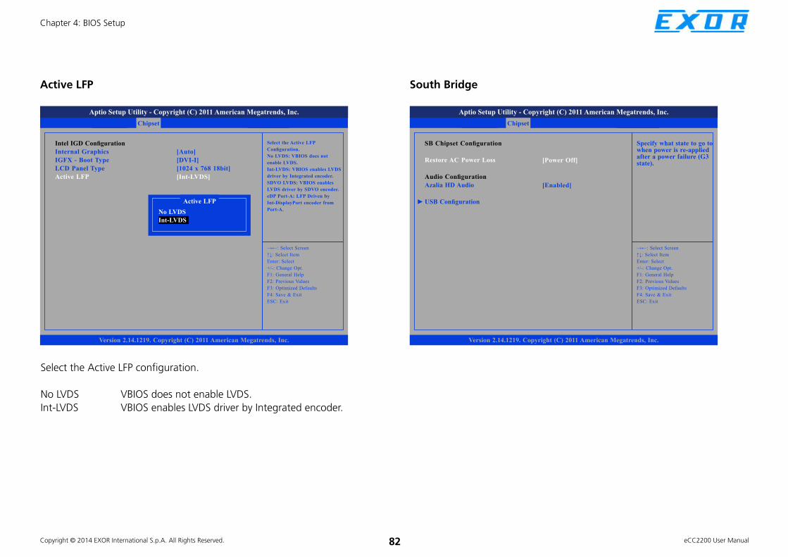
Copyright © 2014 EXOR International S.p.A. All Rights Reserved. 82 eCC2200 User Manual
Chapter 4: BIOS Setup
Save & ExitAdvanced Chipset Boot SecurityMain
Version 2.14.1219. Copyright (C) 2011 American Megatrends, Inc.
Aptio Setup Utility - Copyright (C) 2011 American Megatrends, Inc.
→←: Select Screen
↑↓: Select Item
Enter: Select
+/-: Change Opt.
F1: General Help
F2: Previous Values
F3: Optimized Defaults
F4: Save & Exit
ESC: Exit
Select the Active LFP
Confi guration.
No LVDS: VBIOS does not
enable LVDS.
Int-LVDS: VBIOS enables LVDS
driver by Integrated encoder.
SDVO LVDS: VBIOS enables
LVDS driver by SDVO encoder.
eDP Port-A: LFP Driven by
Int-DisplayPort encoder from
Port-A.
Intel IGD Confi guration
Internal Graphics
IGFX - Boot Type
LCD Panel Type
Active LFP
[Auto]
[DVI-I]
[1024 x 768 18bit]
[Int-LVDS]
Active LFP
Active LFP
No LVDS
Int-LVDS
Select the Active LFP configuration.
No LVDS VBIOS does not enable LVDS.
Int-LVDS VBIOS enables LVDS driver by Integrated encoder.
South Bridge
Save & ExitAdvanced Chipset Boot SecurityMain
Version 2.14.1219. Copyright (C) 2011 American Megatrends, Inc.
Aptio Setup Utility - Copyright (C) 2011 American Megatrends, Inc.
→←: Select Screen
↑↓: Select Item
Enter: Select
+/-: Change Opt.
F1: General Help
F2: Previous Values
F3: Optimized Defaults
F4: Save & Exit
ESC: Exit
Specify what state to go to when power is re-applied after a power failure (G3 state).
SB Chipset Confi guration
Restore AC Power Loss
Audio Confi guration
Azalia HD Audio
USB Confi guration
[Power Off]
[Enabled]
►

Copyright © 2014 EXOR International S.p.A. All Rights Reserved. 83 eCC2200 User Manual
Chapter 4: BIOS Setup
Restore AC Power Loss
Save & ExitAdvanced Chipset Boot SecurityMain
Version 2.14.1219. Copyright (C) 2011 American Megatrends, Inc.
Aptio Setup Utility - Copyright (C) 2011 American Megatrends, Inc.
→←: Select Screen
↑↓: Select Item
Enter: Select
+/-: Change Opt.
F1: General Help
F2: Previous Values
F3: Optimized Defaults
F4: Save & Exit
ESC: Exit
Specify what state to go to when power is re-applied after a power failure (G3 state).
SB Chipset Confi guration
Restore AC Power Loss
Audio Confi guration
Azalia HD Audio
USB Confi guration
[Power Off]
[Enabled]
►Restore AC Power Loss
Power Off
Power On
Power Off When power returns after an AC power failure, the
system’s power is off. You must press the Power button
to power-on the system.
Power On When power returns after an AC power failure, the system
will automatically power-on.
Azalia HD Audio
Save & ExitAdvanced Chipset Boot SecurityMain
Version 2.14.1219. Copyright (C) 2011 American Megatrends, Inc.
Aptio Setup Utility - Copyright (C) 2011 American Megatrends, Inc.
→←: Select Screen
↑↓: Select Item
Enter: Select
+/-: Change Opt.
F1: General Help
F2: Previous Values
F3: Optimized Defaults
F4: Save & Exit
ESC: Exit
Enable / Disable Azalia HD Audio
SB Chipset Confi guration
Restore AC Power Loss
Audio Confi guration
Azalia HD Audio
USB Confi guration
[Power Off]
[Enabled]
►Azalia HD Audio
Disabled
Enabled
This field is used to enable or diable Azalia HD audio.

Copyright © 2014 EXOR International S.p.A. All Rights Reserved. 84 eCC2200 User Manual
Chapter 4: BIOS Setup
USB Configuration
Chipset
Version 2.14.1219. Copyright (C) 2011 American Megatrends, Inc.
Aptio Setup Utility - Copyright (C) 2011 American Megatrends, Inc.
→←: Select Screen
↑↓: Select Item
Enter: Select
+/-: Change Opt.
F1: General Help
F2: Previous Values
F3: Optimized Defaults
F4: Save & Exit
ESC: Exit
Enable / Disable ALL USB
DevicesAll USB Devices
USB 2.0(EHCI) Support
EHCI Controller 1
EHCI Controller 2
UHCI Controller 1
UHCI Controller 2
UHCI Controller 3
UHCI Controller 4
UHCI Controller 5
UHCI Controller 6
[Enabled]
[Enabled]
[Enabled]
[Enabled]
[Enabled]
[Enabled]
[Enabled]
[Enabled]
[Enabled]
[Enabled]
All USB Devices
Chipset
Version 2.14.1219. Copyright (C) 2011 American Megatrends, Inc.
Aptio Setup Utility - Copyright (C) 2011 American Megatrends, Inc.
→←: Select Screen
↑↓: Select Item
Enter: Select
+/-: Change Opt.
F1: General Help
F2: Previous Values
F3: Optimized Defaults
F4: Save & Exit
ESC: Exit
Enable / Disable ALL USB
DevicesAll USB Devices
USB 2.0(EHCI) Support
EHCI Controller 1
EHCI Controller 2
UHCI Controller 1
UHCI Controller 2
UHCI Controller 3
UHCI Controller 4
UHCI Controller 5
UHCI Controller 6
[Enabled]
[Enabled]
[Enabled]
[Enabled]
[Enabled]
[Enabled]
[Enabled]
[Enabled]
[Enabled]
[Enabled]All USB Devices
Disabled
Enabled
This field is used to enable or disable all the USB devices.

Copyright © 2014 EXOR International S.p.A. All Rights Reserved. 85 eCC2200 User Manual
Chapter 4: BIOS Setup
USB 2.0(EHCI) Support
Chipset
Version 2.14.1219. Copyright (C) 2011 American Megatrends, Inc.
Aptio Setup Utility - Copyright (C) 2011 American Megatrends, Inc.
→←: Select Screen
↑↓: Select Item
Enter: Select
+/-: Change Opt.
F1: General Help
F2: Previous Values
F3: Optimized Defaults
F4: Save & Exit
ESC: Exit
Enable / Disable USB 2.0 (EHCI)
SupportAll USB Devices
USB 2.0(EHCI) Support
EHCI Controller 1
EHCI Controller 2
UHCI Controller 1
UHCI Controller 2
UHCI Controller 3
UHCI Controller 4
UHCI Controller 5
UHCI Controller 6
[Enabled]
[Enabled]
[Enabled]
[Enabled]
[Enabled]
[Enabled]
[Enabled]
[Enabled]
[Enabled]
[Enabled]USB 2.0(EHCI) Support
Disabled
Enabled
This field is used to enable or disable USB 2.0 (EHCI) support.
EHCI Controller 1 to EHCI Controller 2
Chipset
Version 2.14.1219. Copyright (C) 2011 American Megatrends, Inc.
Aptio Setup Utility - Copyright (C) 2011 American Megatrends, Inc.
→←: Select Screen
↑↓: Select Item
Enter: Select
+/-: Change Opt.
F1: General Help
F2: Previous Values
F3: Optimized Defaults
F4: Save & Exit
ESC: Exit
Enable / Disable USB 2.0 (EHCI)
SupportAll USB Devices
USB 2.0(EHCI) Support
EHCI Controller 1
EHCI Controller 2
UHCI Controller 1
UHCI Controller 2
UHCI Controller 3
UHCI Controller 4
UHCI Controller 5
UHCI Controller 6
[Enabled]
[Enabled]
[Enabled]
[Enabled]
[Enabled]
[Enabled]
[Enabled]
[Enabled]
[Enabled]
[Enabled]EHCI Controller 1
Disabled
Enabled
These fields are used to enable or disable USB 2.0 (EHCI) support for
controller 1 and 2.
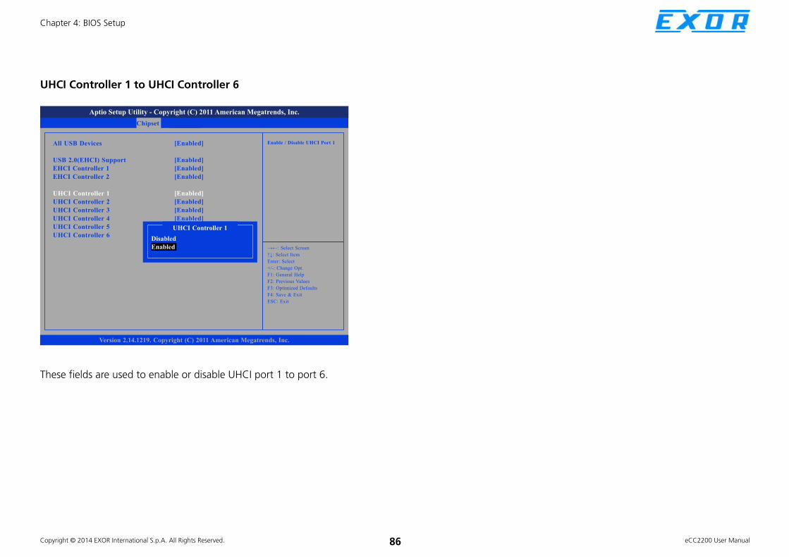
Copyright © 2014 EXOR International S.p.A. All Rights Reserved. 86 eCC2200 User Manual
Chapter 4: BIOS Setup
UHCI Controller 1 to UHCI Controller 6
Chipset
Version 2.14.1219. Copyright (C) 2011 American Megatrends, Inc.
Aptio Setup Utility - Copyright (C) 2011 American Megatrends, Inc.
→←: Select Screen
↑↓: Select Item
Enter: Select
+/-: Change Opt.
F1: General Help
F2: Previous Values
F3: Optimized Defaults
F4: Save & Exit
ESC: Exit
Enable / Disable UHCI Port 1All USB Devices
USB 2.0(EHCI) Support
EHCI Controller 1
EHCI Controller 2
UHCI Controller 1
UHCI Controller 2
UHCI Controller 3
UHCI Controller 4
UHCI Controller 5
UHCI Controller 6
[Enabled]
[Enabled]
[Enabled]
[Enabled]
[Enabled]
[Enabled]
[Enabled]
[Enabled]
[Enabled]
[Enabled]UHCI Controller 1
Disabled
Enabled
These fields are used to enable or disable UHCI port 1 to port 6.

Copyright © 2014 EXOR International S.p.A. All Rights Reserved. 87 eCC2200 User Manual
Chapter 4: BIOS Setup
BootThis section is used to configure the boot features.
Save & ExitAdvanced Chipset Boot SecurityMain
Version 2.14.1219. Copyright (C) 2011 American Megatrends, Inc.
Aptio Setup Utility - Copyright (C) 2011 American Megatrends, Inc.
→←: Select Screen
↑↓: Select Item
Enter: Select
+/-: Change Opt.
F1: General Help
F2: Previous Values
F3: Optimized Defaults
F4: Save & Exit
ESC: Exit
Number of seconds to wait
for setup activation key.
65535(0xFFFF) means indefi nite
waiting.
Boot Confi guration
Setup Prompt Timeout
Bootup NumLock State
Quiet Boot
CSM16 Module Version
GateA20 Active
Option ROM Messages
Interrupt 19 Capture
CSM Support
Boot Option Priorities
Boot Option #1
Hard Drive BBS Priorities
[On]
[Disabled]
07.69
[Upon Request]
[Force BIOS]
[Immediate]
[Enabled]
[SATA PM: Hitachi . . .]
1
Setup Prompt Timeout
This section configures the number of seconds to wait for the setup
activation key.
Bootup NumLock State
Save & ExitAdvanced Chipset Boot SecurityMain
Version 2.14.1219. Copyright (C) 2011 American Megatrends, Inc.
Aptio Setup Utility - Copyright (C) 2011 American Megatrends, Inc.
→←: Select Screen
↑↓: Select Item
Enter: Select
+/-: Change Opt.
F1: General Help
F2: Previous Values
F3: Optimized Defaults
F4: Save & Exit
ESC: Exit
Select the keyboard NumLock
stateBoot Confi guration
Setup Prompt Timeout
Bootup NumLock State
Quiet Boot
CSM16 Module Version
GateA20 Active
Option ROM Messages
Interrupt 19 Capture
CSM Support
Boot Option Priorities
Boot Option #1
Hard Drive BBS Priorities
[On]
[Disabled]
07.69
[Upon Request]
[Force BIOS]
[Immediate]
[Enabled]
[SATA PM: Hitachi . . .]
1
Bootup NumLock State
On
Off
This allows you to determine the default state of the numeric keypad. By
default, the system boots up with NumLock on wherein the function of the
numeric keypad is the number keys. When set to Off, the function of the
numeric keypad is the arrow keys.

Copyright © 2014 EXOR International S.p.A. All Rights Reserved. 88 eCC2200 User Manual
Chapter 4: BIOS Setup
Quiet Boot
Save & ExitAdvanced Chipset Boot SecurityMain
Version 2.14.1219. Copyright (C) 2011 American Megatrends, Inc.
Aptio Setup Utility - Copyright (C) 2011 American Megatrends, Inc.
→←: Select Screen
↑↓: Select Item
Enter: Select
+/-: Change Opt.
F1: General Help
F2: Previous Values
F3: Optimized Defaults
F4: Save & Exit
ESC: Exit
Enables or disables Quiet Boot
optionBoot Confi guration
Setup Prompt Timeout
Bootup NumLock State
Quiet Boot
CSM16 Module Version
GateA20 Active
Option ROM Messages
Interrupt 19 Capture
CSM Support
Boot Option Priorities
Boot Option #1
Hard Drive BBS Priorities
[On]
[Disabled]
07.69
[Upon Request]
[Force BIOS]
[Immediate]
[Enabled]
[SATA PM: Hitachi . . .]
1
Quiet Boot
Disabled
Enabled
Enabled Displays OEM logo instead of the POST messages.
Disabled Displays normal POST messages.
GateA20 Active
Save & ExitAdvanced Chipset Boot SecurityMain
Version 2.14.1219. Copyright (C) 2011 American Megatrends, Inc.
Aptio Setup Utility - Copyright (C) 2011 American Megatrends, Inc.
→←: Select Screen
↑↓: Select Item
Enter: Select
+/-: Change Opt.
F1: General Help
F2: Previous Values
F3: Optimized Defaults
F4: Save & Exit
ESC: Exit
UPON REQUEST - GA20 can be
disabled using BIOS services.
ALWAYS - do not allow disabling
GA20; this option is useful
when any RT code is executed
above 1MB.
Boot Confi guration
Setup Prompt Timeout
Bootup NumLock State
Quiet Boot
CSM16 Module Version
GateA20 Active
Option ROM Messages
Interrupt 19 Capture
CSM Support
Boot Option Priorities
Boot Option #1
Hard Drive BBS Priorities
[On]
[Disabled]
07.69
[Upon Request]
[Force BIOS]
[Immediate]
[Enabled]
[SATA PM: Hitachi . . .]
1
GateA20 Active
Upon Request
Always
Upon Request GA20 can be disabled using BIOS services.
Always Do not allow disabling GA20; this option is useful when
any RT code is executed above 1MB.

Copyright © 2014 EXOR International S.p.A. All Rights Reserved. 89 eCC2200 User Manual
Chapter 4: BIOS Setup
Option ROM Messages
Save & ExitAdvanced Chipset Boot SecurityMain
Version 2.14.1219. Copyright (C) 2011 American Megatrends, Inc.
Aptio Setup Utility - Copyright (C) 2011 American Megatrends, Inc.
→←: Select Screen
↑↓: Select Item
Enter: Select
+/-: Change Opt.
F1: General Help
F2: Previous Values
F3: Optimized Defaults
F4: Save & Exit
ESC: Exit
Set display mode for Option
ROMBoot Confi guration
Setup Prompt Timeout
Bootup NumLock State
Quiet Boot
CSM16 Module Version
GateA20 Active
Option ROM Messages
INT19 Trap Response
CSM Support
Boot Option Priorities
Boot Option #1
Hard Drive BBS Priorities
[On]
[Disabled]
07.69
[Upon Request]
[Force BIOS]
[Immediate]
[Enabled]
[SATA PM: Hitachi . . .]
1
Option ROM Messages
Force BIOS
Keep Current
This field is used to set display mode for Option ROM. The options are Force
BIOS and Keep Current.
INT19 Trap Response
Save & ExitAdvanced Chipset Boot SecurityMain
Version 2.14.1219. Copyright (C) 2011 American Megatrends, Inc.
Aptio Setup Utility - Copyright (C) 2011 American Megatrends, Inc.
→←: Select Screen
↑↓: Select Item
Enter: Select
+/-: Change Opt.
F1: General Help
F2: Previous Values
F3: Optimized Defaults
F4: Save & Exit
ESC: Exit
BIOS reaction on INT19 trapping
by Option ROM:
IMMEDIATE - execute the
trap right away; POSTPONED
- execute the trap during
legacy boot.
Boot Confi guration
Setup Prompt Timeout
Bootup NumLock State
Quiet Boot
CSM16 Module Version
GateA20 Active
Option ROM Messages
INT19 Trap Response
CSM Support
Boot Option Priorities
Boot Option #1
Hard Drive BBS Priorities
[On]
[Disabled]
07.69
[Upon Request]
[Force BIOS]
[Immediate]
[Enabled]
[SATA PM: Hitachi . . .]
1
INT19 Trap Response
Immediate
Postponed
Allows Option ROMs to trap Interrupt 19 when enabled.
Immediate Execute the trap right away.
Postponed Execute the trap during legacy boot.

Copyright © 2014 EXOR International S.p.A. All Rights Reserved. 90 eCC2200 User Manual
Chapter 4: BIOS Setup
CSM Support
Save & ExitAdvanced Chipset Boot SecurityMain
Version 2.14.1219. Copyright (C) 2011 American Megatrends, Inc.
Aptio Setup Utility - Copyright (C) 2011 American Megatrends, Inc.
→←: Select Screen
↑↓: Select Item
Enter: Select
+/-: Change Opt.
F1: General Help
F2: Previous Values
F3: Optimized Defaults
F4: Save & Exit
ESC: Exit
Enable/Disable CSM Support, If
Auto is selected, based on OS,
CSM will be enabled/disabled
automatically.
Boot Confi guration
Setup Prompt Timeout
Bootup NumLock State
Quiet Boot
CSM16 Module Version
GateA20 Active
Option ROM Messages
INT19 Trap Response
CSM Support
Boot Option Priorities
Boot Option #1
Hard Drive BBS Priorities
[On]
[Disabled]
07.69
[Upon Request]
[Force BIOS]
[Immediate]
[Enabled]
[SATA PM: Hitachi . . .]
1
CSM Support
Disabled
Enabled
This field is used to enable or disable CSM support, if Auto option is selected,
based on OS, CSM will be enabled or disabled automatically.
Auto
Boot Option Priorities (Boot Option #1)
Save & ExitAdvanced Chipset Boot SecurityMain
Version 2.14.1219. Copyright (C) 2011 American Megatrends, Inc.
Aptio Setup Utility - Copyright (C) 2011 American Megatrends, Inc.
→←: Select Screen
↑↓: Select Item
Enter: Select
+/-: Change Opt.
F1: General Help
F2: Previous Values
F3: Optimized Defaults
F4: Save & Exit
ESC: Exit
Sets the system boot orderBoot Confi guration
Setup Prompt Timeout
Bootup NumLock State
Quiet Boot
CSM16 Module Version
GateA20 Active
Option ROM Messages
INT19 Trap Response
CSM Support
Boot Option Priorities
Boot Option #1
Hard Drive BBS Priorities
[On]
[Disabled]
07.69
[Upon Request]
[Force BIOS]
[Immediate]
[Enabled]
[SATA PM: Hitachi . . .]
1
Boot Option #1
SATA PM: Hitachi HTE545016B9A
Disabled
This field is used to adjust the boot sequence of the system. Boot Option #1
is the first boot device that the system will boot from, next will be #2 and
so forth.

Copyright © 2014 EXOR International S.p.A. All Rights Reserved. 91 eCC2200 User Manual
Chapter 4: BIOS Setup
Hard Drive BBS Priorities (Boot Option #1)
Save & ExitAdvanced Chipset Boot SecurityMain
Version 2.14.1219. Copyright (C) 2011 American Megatrends, Inc.
Aptio Setup Utility - Copyright (C) 2011 American Megatrends, Inc.
→←: Select Screen
↑↓: Select Item
Enter: Select
+/-: Change Opt.
F1: General Help
F2: Previous Values
F3: Optimized Defaults
F4: Save & Exit
ESC: Exit
Sets the system boot orderBoot Option #1
Boot Option #2
[SATA PM: Hitachi . . .]
[SATA PS: 32GB SAT . . .]
Boot Option #1
SATA PM: Hitachi HTE545016B9A
SATA PS: 32GB SATA Flash Drive
Sets the first legacy device to boot from.
Disabled
Hard Drive BBS Priorities (Boot Option #2)
Save & ExitAdvanced Chipset Boot SecurityMain
Version 2.14.1219. Copyright (C) 2011 American Megatrends, Inc.
Aptio Setup Utility - Copyright (C) 2011 American Megatrends, Inc.
→←: Select Screen
↑↓: Select Item
Enter: Select
+/-: Change Opt.
F1: General Help
F2: Previous Values
F3: Optimized Defaults
F4: Save & Exit
ESC: Exit
Sets the system boot orderBoot Option #1
Boot Option #2
[SATA PM: Hitachi . . .]
[SATA PS: 32GB SAT . . .]
Boot Option #2
SATA PM: Hitachi HTE545016B9A
SATA PS: 32GB SATA Flash Drive
Sets the second legacy device to boot from.
Disabled

Copyright © 2014 EXOR International S.p.A. All Rights Reserved. 92 eCC2200 User Manual
Chapter 4: BIOS Setup
Security
Save & ExitAdvanced Chipset Boot SecurityMain
Version 2.14.1219. Copyright (C) 2011 American Megatrends, Inc.
Aptio Setup Utility - Copyright (C) 2011 American Megatrends, Inc.
→←: Select Screen
↑↓: Select Item
Enter: Select
+/-: Change Opt.
F1: General Help
F2: Previous Values
F3: Optimized Defaults
F4: Save & Exit
ESC: Exit
Set Administrator PasswordPassword Description
If ONLY the Administrator’s password is set,
then this only limits access to Setup and is
only asked for when entering Setup.
If ONLY the User’s password is set, then this
is a power on password and must be entered to
boot or enter Setup. In Setup the User Will
have Administrator rights.
The password length must be
in the following range:
Minimum length 3
Maximum length 20
Administrator Password
User Password
Administrator Password
Select this to reconfigure the administrator’s password.
User Password
Select this to reconfigure the user’s password.
Save & ExitAdvanced Chipset Boot SecurityMain
Version 2.14.1219. Copyright (C) 2011 American Megatrends, Inc.
Aptio Setup Utility - Copyright (C) 2011 American Megatrends, Inc.
→←: Select Screen
↑↓: Select Item
Enter: Select
+/-: Change Opt.
F1: General Help
F2: Previous Values
F3: Optimized Defaults
F4: Save & Exit
ESC: Exit
Exit systm setup after saving the changes.
Save Changes and Exit
Discard Changes and Exit
Save Changes and Reset
Discard Changes and Reset
Save Options
Save Changes
Discard Changes
Restore Defaults
Save as User Defaults
Restore User Defaults
Boot Override
SATA PM: Hitachi HTE545016B9A
Launch EFI Shell from fi lesystem device
Save & Exit
Save Changes and Exit
To save the changes and exit the Setup utility, select this field then press
<Enter>. A dialog box will appear. Confirm by selecting Yes. You can also
press <F4> to save and exit Setup.
Discard Changes and Exit
To exit the Setup utility without saving the changes, select this field then
press <Enter>. You may be prompted to confirm again before exiting. You
can also press <ESC> to exit without saving the changes.

Copyright © 2014 EXOR International S.p.A. All Rights Reserved. 93 eCC2200 User Manual
Chapter 4: BIOS Setup
Save Changes and Reset
To save the changes and reset, select this field then press <Enter>. A dialog
box will appear. Confirm by selecting Yes.
Discard Changes and Reset
To exit the Setup utility and reboot the system without saving the changes,
select this field then press <Enter>. You may be prompted to confirm again
before exiting.
Save Changes
To save changes and continue configuring the BIOS, select this field then
press <Enter>. A dialog box will appear. Confirm by selecting Yes.
Discard Changes
To discard the changes, select this field then press <Enter>. A dialog box will
appear. Confirm by selecting Yes to discard all changes made and restore
the previously saved settings.
Restore Defaults
To restore the BIOS to default settings, select this field then press <Enter>. A
dialog box will appear. Confirm by selecting Yes.
Save as User Defaults
To use the current configurations as user default settings for the BIOS, select
this field then press <Enter>. A dialog box will appear. Confirm by selecting
Yes.
Restore User Defaults
To restore the BIOS to user default settings, select this field then press
<Enter>. A dialog box will appear. Confirm by selecting Yes.
Boot Override
To bypass the boot sequence from the Boot Option List and boot from a
particular device, select the desired device and press <Enter>.
Launch EFI Shell from filesystem device
To launch EFI shell from a filesystem device, select this field and press
<Enter>.

Copyright © 2014 EXOR International S.p.A. All Rights Reserved. 94 eCC2200 User Manual
Appendix A: GPI/O Programming Guide
APPENDIX A: GPI/O PROGRAMMING GUIDE
Digital I/O (Digital Input/Output) pins are provided for custom system design.
This appendix provides definitions and its default setting for the Digital I/O
pins in the eCC2200. The pin definition is shown is the following table:
PIN Description PIN Description
1 +5V 2 GND
3 GPO24 4 GPI20
5 GPO25 6 GPI21
7 GPO26 8 GPI22
9 GPO27 10 GPI23
IO base address : A00h
Bit0 : GPI20
Bit1 : GPI21
Bit2 : GPI22
Bit3 : GPI23
Bit4 : GPO24
Bit5 : GPO25
Bit6 : GPO26
Bit7 : GPO27
1. Read/Write GPIO data by I/O port A04h

Copyright © 2014 EXOR International S.p.A. All Rights Reserved. 95 eCC2200 User Manual
Appendix B: Watchdog Timer
APPENDIX B: WATCHDOG TIMER
eCC2200 Watch Dog Function Configuration Sequence Description:
Start
Step1. See “SetupWDT” procedure
#Setup Watchdog Timer Environment
Step2. See “TimeBaseWDT” procedure
#Initial Watchdog Timer.
Users can select second or minute.
Step3. See “TimeCountWDT” procedure
#Set Watchdog Timer Time-out Value.
Users can set time-out value.
Step4: See ExitSetup procedure
#Exit Setup Environment
End

Copyright © 2014 EXOR International S.p.A. All Rights Reserved. 96 eCC2200 User Manual
Appendix B: Watchdog Timer
===============================================
TimeBaseWDT PROC
mov al, 72h
out 2eh, al
mov al, 10h ;Set WDT reset upon PWROK
or al, 80h ;Here!! set 80h for second, set 00h for minute
out 2fh, al
ret
TimeBaseWDT ENDP
===============================================
TimeCountWDT PROC
mov al, 73h ;WDT Time-out register.
out 2eh, al
mov al, 03h ;Here!! Set count 3.
out 2fh, al
ret
TimeCountWDT ENDP
===============================================
ExitSetup PROC
mov al, 02h
out 2eh, al
mov al, 02h
out 2fh, al
ret
ExitSetup ENDP
===============================================
===============================================
SetupWDT PROC
mov dx, 2eh
mov al, 087h
out dx, al
nop
nop
mov al, 01h
out dx, al
nop
nop
mov al, 55h
out dx, al
nop
nop
out dx, al ;Write operations to special address
port (2E) for entering MB PnP Mode.
mov al, 07h
out 2eh, al
mov al, 07h ;Select logical device for Watch Dog.
out 2fh, al
ret
SetupWDT ENDP