Embed Size (px)
Citation preview

Expanding the Applications of Stereo Machine VisionBy Eiji Iwai, Senior Engineer, Embedded Technology Department, Solution Business Division, FUJISOFT
The Design Team:
Challenge:
Solution:
FUJISOFT is an intellectual property (IP) core and design service provider with over 20 years of experience supporting Altera® FPGA projects for customers in the embedded medical, industrial, and consumer markets.
Stereo vision carries far more information about objects, their distance, and their behavior than using a video from a single camera. Hence, stereo cameras are increasingly used in advanced driver assistance systems (ADAS). However, if stereo vision processing could be done at a lower cost and power consumption, and with a higher frame rate, it would have a vast range of other applications in industrial, transportation, and aviation systems.
Dr. Keiji Saneyoshi, Associate Professor of Tokyo Institute of Technology and an authority on stereo camera technologies for vehicles, has developed a new stereo vision-processing algorithm utilizing the features of FPGAs. The result is a Stereo Vision processor in a compact FPGA with higher frame rate than can be achieved with software on a multicore digital signal processor (DSP).
Today, stereo technology is one of the sensing technologies utilized in the
automotive field for self-driving cars and crash safety. Stereo technology can be
used in other business fields as well. However, stereo processing faces significant
challenges outside the automotive environment.
Here are three main case examples that take advantage of the Stereo Vision IP
Suite. First, consider using stereo vision IP for auto-detecting ruts on the road.
Normally, the road management company checks and finds ruts on the road by
using radar installed in a special automobile. When this system is at work, the crew
must block the roads and assign a flagman, which costs a lot. However, the Stereo
Vision IP Suite does not need any special automobile, because it can be on any
vehicle. For instance, if it is on public transportation vehicles such as a taxi or a bus,
routine traffic will daily detect ruts on the road automatically. Stereo vision helps
to cut costs and reduces the time to gather the data needed for road
maintenance (Figure 1).
The Project
D E S I G N S O L U T I O N :
Figure 1. Taxis with stereo vision could crowd-source a real-time map of road conditions.
A C U S T O M E R S U C C E S S S T O R Y
D E S I G N S O L U T I O N
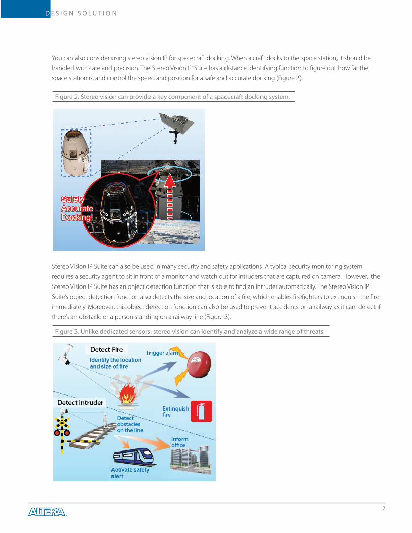
Stereo Vision IP Suite can also be used in many security and safety applications. A typical security monitoring system
requires a security agent to sit in front of a monitor and watch out for intruders that are captured on camera. However, the
Stereo Vision IP Suite has an onject detection function that is able to find an intruder automatically. The Stereo Vision IP
Suite’s object detection function also detects the size and location of a fire, which enables firefighters to extinguish the fire
immediately. Moreover, this object detection function can also be used to prevent accidents on a railway as it can detect if
there’s an obstacle or a person standing on a railway line (Figure 3).
You can also consider using stereo vision IP for spacecraft docking. When a craft docks to the space station, it should be
handled with care and precision. The Stereo Vision IP Suite has a distance identifying function to figure out how far the
space station is, and control the speed and position for a safe and accurate docking (Figure 2).
2
Figure 2. Stereo vision can provide a key component of a spacecraft docking system.
Figure 3. Unlike dedicated sensors, stereo vision can identify and analyze a wide range of threats.

D E S I G N S O L U T I O N
FUJISOFT co-developed the Stereo Vision IP Suite with Altera. It optimized stereo technology for a compact, low-power
FPGA by applying an algorithm developed by Dr. Keiji Saneyoshi, Associate Professor of Tokyo Institute of Technology, who
is often cited as the authority on stereo camera technologies for vehicles. His algorithm specifically utilizes the features of
the FPGA, enabling Stereo Vision processing at higher frame rates than can be achieved with software-based processing on
multicore CPUs or even multicore DSPs.
By transforming conventional stereo-processing algorithms into a clean four-stage pipeline, Dr. Saneyoshi’s algorithm
allows the entire task to be implemented in a combination of pipelined hardware in an FPGA fabric and software on a pair
of ARM® Cortex®-A9 CPUs (Figure 4). Both the fabric and the CPUs are contained in a single Altera® Cyclone® V SoC.
The Design Solution
3
The fundamental requirements of stereo vision processing are well understood. You must rectify images from wide-angle
cameras, since wide-angle distortions will lead to incorrect distance and location estimates. You must extract differences
between the two (usually simultaneous) images, and from that information infer the presence of objects, their location,
range, and characteristics.
In research environments these tasks are normally done in software on CPUs. In high-end ADAS, design cycles, hardware
budgets, and the availability of ample power and cooling may permit use of power-hungry computational hardware or
customer-specific SoCs. However, FUJISOFT plans to extend stereo techniques to embedded applications that do not
have long development times, are sensitive to processing latency, and have limited processing power.
The Design Challenge
Figure 4. The Block Diagram of Stereo Vision IP Suite
Cyclone V SoC
HPS Block(ARM Cortex-A9 Dual Core) Object
Tracking
ApplicationViewer
ObjectDetection
StereoVision
Recti�cationDistortionCorrection
Image Sensor I/F
Image Sensor I/F
R-Camera
L-Camera

D E S I G N S O L U T I O ND E S I G N S O L U T I O N
The stereo vision-processing pipeline conmprises three primary stages. Each of these stages
corresponds to a conceptually clear transformation of the data, successively preparing the image, extracting the
information revealed by comparing the two images, and using that information to identify and analyze objects. We can
examine each of these functions in order.
Dr. Saneyoshi’s technique of Rectification Distortion Correction removes the distortion on the left and right camera,
enabling you to match the pictures on the left and right camera with an error of less than 0.1 pixel.
To capture a wide view, vision systems generally use wide-angle lenses. But such lenses, although they are inexpensive,
introduce distortion around the picture. This distortion creates a bottleneck further down the pipeline in recognizing the
accurate distance of particular objects from the cameras. Our system automatically removes this distortion, and this
function is called Rectification Distortion Correction. The method is shown in Figure 5. First, capture a dedicated distortion
chart, and find the lattice coordinates by analyzing the picture automatically. Then, calculate each lens’s parameters of the
distortion correction from the chart data. In this way, the Rectification Distortion Correction function removes the distortion
in every frame by using the lens’s own parameters.
Stereo Vision is the key function of the Stereo Vision IP Suite. It detects the left-versus-right disparity using two cameras. If
the disparity is large, the object is close; on the contrary, if the disparity is small, the object is far away. These judgements are
the basis of distance recognition for the object.
Theory of Operation
Function1. Rectification Distortion Correction
Function 2. Stereo Vision
Figure 5. The Imaging of Rectification Distortion Correction
Before the correction After the correction

D E S I G N S O L U T I O N
There are two kinds of methods to calculate the disparity: semi-global block matching (SGBM) and sum of absolute
difference (SAD). Dr. Saneyoshi adopts the latter one (Figure 6). SGBM obtains the accurate disparity by interpolation
calculation of the outline (edge) and other features. However, this method needs much computation cost and a large
circuit, and even so the outlines of objects are sometimes ambiguous. Meanwhile, SAD needs less computation cost and a
smaller circuit design, so we can associate an object with its accurate outline to detect the object (details of which are
below: see Figure 6). In addition, SAD obtains accurate stereo matching data, necessary to do pattern matching at sub-pixel
resolution. Sub-pixel processing is the process of pattern matching by detailed interpolation, thereby producing highly
accurate disparity data. By this process, it makes it possible to get disparity data that is actually more accurate than the
resolution of the image sensor. Also, areas of the image that are visible from only one of the two cameras, called
occlusion areas, make it hard to get accurate disparity data, so we need another filter process to solve this problem.
Occlusion area is inversely proportional to distance to the objects.
How do we do the matching process? Stereo Vision obtains the block disparity data (4×4 pixels) by pattern-matching the
image from the base camera against the image from the reference camera (Figure 7).
Figure 6. The Image of Sum of Absolute Difference (SAD) system
Figure 7. The Image of 4x4 Block Matching

D E S I G N S O L U T I O N
The key point of the object detection function is to calculate the distance from the cameras to an object. From the disparity
and the distance data, Stereo Vision IP Suite detects a three-dimensional object and identifies its location and size. For
example, if the algorithm detects a car, it identifies each of the body parts, such as a trunk and a bumper, by the difference
of distance from the cameras (Figure 8). In this way, Stereo Vision IP Suite identifies the road surface, and
discriminates an object. Furthermore, this block has a second function which is object tracking.
What is object tracking? Using 3D-coordinate data and motion-vector data, the algorithm predicts the object’s location in
the next following frame, and then the object data in the first frame will be linked with the actual object data in the next
frame (Figure 9). Vehicle A and vehicle B are moving in a frame at the same time, but vehicle C is tracking each of them
separately by calculating their direction and speed.
Function 3. Object Detection and Object Tracking
Figure 8. The Image of Object Detection
Figure 9. The Image of Object Tracking

D E S I G N S O L U T I O N
© 2015 Altera Corporation. All rights reserved. ALTERA, ARRIA, CYCLONE, ENPIRION, MAX, MEGACORE, NIOS, QUARTUS and STRATIX words and logos are trademarks of Altera Corporation and registered in the U.S. Patent and Trademark Office and are trademarks or registered trademarks in other countries. All other words and logos identified as trademarks or service marks are the property of their respective holders as described at www.altera.com/legal. November 2015.
DS-1004-1.0
Altera Corporation101 Innovation DriveSan Jose, CA 95134USATelephone: (408) 544 7000www.altera.com
Altera European HeadquartersHolmers Farm WayHigh WycombeBuckinghamshireHP12 4XFUnited KingdomTelephone: (44) 1 494 602 000
Altera European Trading Company Ltd.Building 2100Cork Airport Business Park,Cork, Republic of IrelandTelephone: +353 21 454 7500
Altera Japan Ltd.Shinjuku i-Land Tower 32F6-5-1, Nishi ShinjukuShinjuku-ku, Tokyo 163-1332JapanTelephone: (81) 3 3340 9480www.altera.co.jp
Altera International Ltd.Unit 11- 18, 9/FMillennium City 1, Tower 1388 Kwun Tong RoadKwun TongKowloon, Hong Kong Telephone: (852) 2945 7000www.altera.com.cn
Altera Corporation Technology CenterPlot 6, Bayan Lepas TechnoplexMedan Bayan Lepas11900 Bayan Lepas Penang, MalaysiaTelephone: 604 636 6100
Results
“This Design Solution describes an actual design that has been developed. However, it does not represent a supported product or reference design, and is not orderable from Altera. If you would like additional information, please contact Altera’s authorized distributor”.
Table 1 shows the comparison of FPGA and DSP implementations. FPGAs with low power consumption shows higher
performance. An FPGA processes twice as many frames per second as the DSP with 1/10 of power consumption. Needless
to say, heat generation is in proportion to power consumption, so the FPGA does not need cooling equipment inside.
FUJISOFT is planning to develop new object recognition features that can distinguish human beings, objects, and white
lanes as well as self-calibration features that calibrate the displacement of camera’s position automatically through
vibration. In conclusion, FPGA is a customizable and flexible device, so engineers are able to add their own logic to the
Stereo Vision IP Suite. The suite will make it easy for engineers to apply high-mix, low-volume production that will open the
way to a wide variety of applications in the near future.
Table 1. Comparison FPGA and DSP Implementations
*Assumed multiple core DSP, operation frequency 1.2 GHz
Resolution Frame Rate Power Consumption Heating Value
FPGA1280x720
30 fps 1.3 W No need fan
DSP 15 fps 13.5 W High