Embed Size (px)
Citation preview

Direct Service Done Right
07 9513 + 07 9516
Expansion Joint SystemsCatalog

Download Drawings, CAD, Spec, and LEED documents at www.Nystrom.com2
Direct Service Done Right
entrance mats + framesentrance floor grilles12 4813 + 12 4816
stair treads + nosings05 5000
fall protection05 5213 / 07 7200div
5
smoke vents07 7200
roof hatches07 7200
preformed joint seals + expansion joint systems07 9100 + 07 9513
div7
access doors08 3100
floor doors08 3483div
8
wall + door protection10 2600
fire protection cabinet + fire extinguishers10 4413 + 10 4416
div10
div12
For over 50 years Nystrom has been the go to manufacturer for specialty building products.
Today we provide a wide range of floor, roof and safety related access products that help create safer, more accessible buildings.
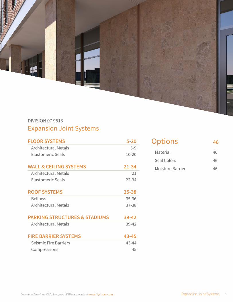
3Download Drawings, CAD, Spec, and LEED documents at www.Nystrom.com Expansion Joint Systems
Options 46
Material 46
Seal Colors 46
Moisture Barrier 46
DIVISION 07 9513
Expansion Joint Systems
FLOOR SYSTEMS 5-20Architectural Metals 5-9Elastomeric Seals 10-20
WALL & CEILING SYSTEMS 21-34Architectural Metals 21Elastomeric Seals 22-34
ROOF SYSTEMS 35-38Bellows 35-36Architectural Metals 37-38
PARKING STRUCTURES & STADIUMS 39-42Architectural Metals 39-42
FIRE BARRIER SYSTEMS 43-45Seismic Fire Barriers 43-44Compressions 45

DIRECT SERVICE
ProductsPeople
Process
Nystrom offers a broad line of specialty building products to better serve construction professionals and architects.
We have customer focused professionals and hassle-free processes that directly serve and simplify the building process.
Direct Service Done Right
PRODUCTS
standard & custom designs, warehousing, quality assurance, exceptional warranties, leed certification, labeling & tagging
PEOPLE
architects, engineers, designers, estimators, construction professionals, and service specialists
PROCESS
estimating & bid design support, tech support, logistics support, installation support, cad, revit/bim
TIME EFFICIENCY SERVICE
SPECIFICATION SUPPORT
By giving architects, designers and
contractors open access to our
expert team, we simplify the process
of specifying and procuring access
products from design through
delivery and installation.
5Download Drawings, CAD, Spec, and LEED documents at www.Nystrom.com Expansion Joint Systems | FLOOR SYSTEMS
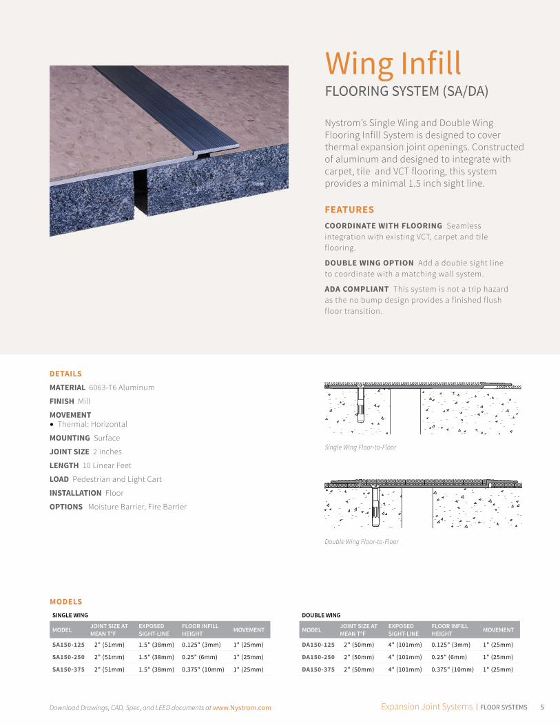
Wing InfillFLOORING SYSTEM (SA/DA)
Nystrom’s Single Wing and Double Wing Flooring Infill System is designed to cover thermal expansion joint openings. Constructed of aluminum and designed to integrate with carpet, tile and VCT flooring, this system provides a minimal 1.5 inch sight line.
FEATURESCOORDINATE WITH FLOORING Seamless integration with existing VCT, carpet and tile flooring.
DOUBLE WING OPTION Add a double sight line to coordinate with a matching wall system.
ADA COMPLIANT This system is not a trip hazard as the no bump design provides a finished flush floor transition.
DETAILS
MATERIAL 6063-T6 Aluminum
FINISH Mill
MOVEMENT • Thermal: Horizontal
MOUNTING Surface
JOINT SIZE 2 inches
LENGTH 10 Linear Feet
LOAD Pedestrian and Light Cart
INSTALLATION Floor
OPTIONS Moisture Barrier, Fire Barrier
MODELSSINGLE WING
MODEL JOINT SIZE AT MEAN T°F
EXPOSED SIGHT-LINE
FLOOR INFILL HEIGHT MOVEMENT
SA150-125 2" (51mm) 1.5" (38mm) 0.125" (3mm) 1" (25mm)
SA150-250 2" (51mm) 1.5" (38mm) 0.25" (6mm) 1" (25mm)
SA150-375 2" (51mm) 1.5" (38mm) 0.375" (10mm) 1" (25mm)
DOUBLE WING
MODEL JOINT SIZE AT MEAN T°F
EXPOSED SIGHT-LINE
FLOOR INFILL HEIGHT MOVEMENT
DA150-125 2" (50mm) 4" (101mm) 0.125" (3mm) 1" (25mm)
DA150-250 2" (50mm) 4" (101mm) 0.25" (6mm) 1" (25mm)
DA150-375 2" (50mm) 4" (101mm) 0.375" (10mm) 1" (25mm)
Single Wing Floor-to-Floor
Double Wing Floor-to-Floor

Download Drawings, CAD, Spec, and LEED documents at www.Nystrom.com6
Single Wing HingedFLOORING INFILL SYSTEM (FA)
The Single Wing Hinged Flooring Infill System is designed with a hinged cover to accommodate horizontal and vertical thermal movement. This surface mounted system is designed to integrate with carpet and VCT flooring and provides a minimal sight line.
DETAILS
MATERIAL 6063-T6 Aluminum
FINISH Mill
MOVEMENT • Thermal: Horizontal and Vertical
MOUNTING Surface
JOINT SIZE 3 inches
LENGTH 10 Linear Feet
LOAD Pedestrian and Light Cart
INSTALLATION Floor
OPTIONS Moisture Barrier, Fire Barrier
FEATURESHINGED DESIGN Constructed with a single wing, hinged design to allow for limited vertical movement.
INTEGRATED FLOORING Designed to coordinate with main flooring material and accepts floor infill.
SURFACE MOUNT No block out is required. Simply screw onto subfloor.
MODELS
MODEL JOINT SIZE AT MEAN T°F
EXPOSED SIGHT-LINE
FLOOR INFILL HEIGHT MOVEMENT
FA150-125 3" (75mm) 1.5" (38mm) 0.125" (3mm) 1" (25mm)
FA150-250 3" (75mm) 1.5" (38mm) 0.25" (6mm) 1" (25mm)
FA150-375 3" (75mm) 1.5" (38mm) 0.375" (10mm) 1" (25mm)

7Download Drawings, CAD, Spec, and LEED documents at www.Nystrom.com Expansion Joint Systems | FLOOR SYSTEMS
Architectural Aluminum FLOORING SYSTEM (RA)
The Architectural Aluminum Flooring System, with dual mounting, allows for flush mounting next to tile or carpeting. The overlap covers joint opening when movement occurs. The exposed cover plate is manufactured with continuous serrations providing an anti-slip surface to reduce trips, slips and falls.
FEATURESANTI-SLIP SURFACE Designed with serrations to create an anti-slip surface.
SURFACE MOUNT No block out is required - simply screw onto the existing subfloor.
ARCHITECTURAL METAL The entire system of metal is exposed for architectural aesthetics. The neighboring flooring infill simply butts against the system.
DETAILS
MATERIAL 6063-T6 Aluminum
FINISH Mill
MOVEMENT • Thermal: Vertical
MOUNTING Surface
JOINT SIZE 1 inch
LENGTH 10 Linear Feet
LOAD Pedestrian and Light Cart
INSTALLATION Floor
OPTIONS Moisture Barrier, Fire Barrier
MODELS
MODEL JOINT SIZE AT MEAN T°F
EXPOSED SIGHT-LINE
FLOOR INFILL HEIGHT MOVEMENT
RA125 1" (25mm) 9.25" (235mm) 0.125" (3mm) .75" (20mm)
RA375 1" (25mm) 8.5" (212mm) 0.375" (10mm) .75" (20mm)
Download Drawings, CAD, Spec, and LEED documents at www.Nystrom.com8
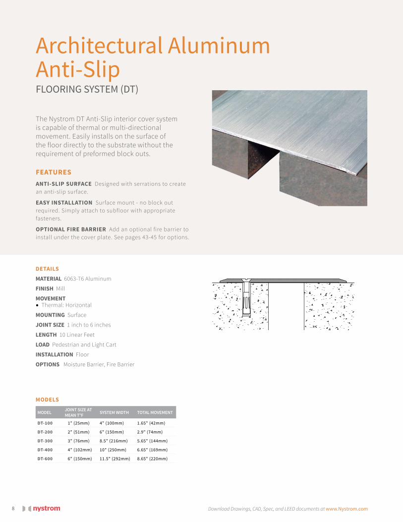
Architectural Aluminum Anti-Slip FLOORING SYSTEM (DT)
The Nystrom DT Anti-Slip interior cover system is capable of thermal or multi-directional movement. Easily installs on the surface of the floor directly to the substrate without the requirement of preformed block outs.
DETAILS
MATERIAL 6063-T6 Aluminum
FINISH Mill
MOVEMENT • Thermal: Horizontal
MOUNTING Surface
JOINT SIZE 1 inch to 6 inches
LENGTH 10 Linear Feet
LOAD Pedestrian and Light Cart
INSTALLATION Floor
OPTIONS Moisture Barrier, Fire Barrier
FEATURESANTI-SLIP SURFACE Designed with serrations to create an anti-slip surface.
EASY INSTALLATION Surface mount - no block out required. Simply attach to subfloor with appropriate fasteners.
OPTIONAL FIRE BARRIER Add an optional fire barrier to install under the cover plate. See pages 43-45 for options.
MODELS
MODEL JOINT SIZE AT MEAN T°F SYSTEM WIDTH TOTAL MOVEMENT
DT-100 1" (25mm) 4" (100mm) 1.65" (42mm)
DT-200 2" (51mm) 6" (150mm) 2.9" (74mm)
DT-300 3" (76mm) 8.5" (216mm) 5.65" (144mm)
DT-400 4" (102mm) 10" (250mm) 6.65" (169mm)
DT-600 6" (150mm) 11.5" (292mm) 8.65" (220mm)

9Download Drawings, CAD, Spec, and LEED documents at www.Nystrom.com Expansion Joint Systems | FLOOR SYSTEMS
MODELS
MODEL JOINT SIZE AT MEAN T°F SYSTEM WIDTH TOTAL MOVEMENT
SW-300 1" - 3" (25-76mm) 5" (125mm) 1" - 3" (25-76mm)
Architectural Aluminum CORNER SYSTEM (SW)
The Architectural Aluminum Corner System is designed to give an aesthetically pleasing cover plate around the Corner of the floor to wall corner.
FEATURESSURFACE MOUNT No block out is required. Simply attach to back wall with appropriate fasteners.
STYLISH APPEARANCE Complementary addition to your Corner floor-to-wall covering.
OPTIONAL MOISTURE BARRIER Add an optional moisture barrier under the cover plate. See page 46 for moisture barrier options.
DETAILS
MATERIAL 6063-T6 Aluminum
FINISH Clear Anodized
MOVEMENT • Thermal: Horizontal
MOUNTING Surface
JOINT SIZE 1 inch to 3 inches
LENGTH 10 Linear Feet
LOAD Pedestrian and Light Cart
INSTALLATION Floor
OPTIONS Moisture Barrier, Fire Barrier
Download Drawings, CAD, Spec, and LEED documents at www.Nystrom.com10
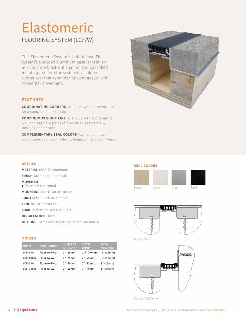
Elastomeric FLOORING SYSTEM (LCF/W)
This Elastomeric System is built to last. The system’s extruded aluminum base is installed in a concrete block out channel and backfilled in. Integrated into the system is a colored rubber seal that expands and compresses with horizontal movement.
DETAILS
MATERIAL 6063-T6 Aluminum
FINISH Mill and Rubber Seal
MOVEMENT • Thermal: Horizontal
MOUNTING Block Out or Surface
JOINT SIZE 1 inch or 2 inches
LENGTH 10 Linear Feet
LOAD Pedestrian and Light Cart
INSTALLATION Floor
OPTIONS Seal Color, Moisture Barrier, Fire Barrier
FEATURESCOORDINATING CORNERS Available with corner option for a complete floor solution.
CONTINUOUS SIGHT LINE Available with coordinating wall and ceiling systems to provide an aesthetically pleasing appearance.
COMPLEMENTARY SEAL COLORS Available in four elastomeric seal color options: beige, white, gray or black.
Floor-to-Floor
Floor-to-Wall/Corner
MODELS
MODEL INSTALLATION JOINT SIZE AT MEAN T°F
SYSTEM WIDTH
TOTAL MOVEMENT
LCF-100 Floor-to-Floor 1" (25mm) 1.5" (40mm) .5" (12mm)
LCF-100W Floor-to-Wall 1" (25mm) 2" (50mm) .5" (12mm)
LCF-200 Floor-to-Floor 2" (50mm) 2" (50mm) 1" (25mm)
LCF-200W Floor-to-Wall 2" (50mm) 3" (75mm) 1" (25mm)
SEAL COLORS
Beige GrayWhite Black

11Download Drawings, CAD, Spec, and LEED documents at www.Nystrom.com Expansion Joint Systems | FLOOR SYSTEMS
Elastomeric System TOP MOUNT APPLICATION (LCFS/W)
Elastomeric System FLOORING INFILL APPLICATION (LCFC/W)
Elastomeric System TILE APPLICATION (LCFT/W)
The Top Mount System is designed for mounting directly over the expansion joint on top of the flooring material. The beveled edge provides smooth transition walking surface.
Nystrom’s Flooring Infill Elastomeric Expansion Joint System is a surface mounted system that is designed for mounting directly over the expansion joint and receives flooring on top of the installed assembly.
This system is designed to be mounted directly over the joint openings for tile applications. The flooring mounts flush to the edge of the assembly.
Floor-to-Floor
Floor-to-Floor
Floor-to-Floor
Floor-to-Wall/Corner
Floor-to-Wall/Corner
Floor-to-Wall/Corner
MODELS
MODELS
MODELS
MODEL INSTALLATION JOINT SIZE AT MEAN T°F SYSTEM WIDTH TOTAL
MOVEMENT
LCFS-100 Floor-to-Floor 1" (25mm) 5" (127mm) 0.5" (13mm)
LCFS-100W Floor-to-Wall 1" (25mm) 2.75" (70mm) 0.5" (13mm)
LCFS-200 Floor-to-Floor 2" (51mm) 6" (152mm) 1" (25mm)
LCFS-200W Floor-to-Wall 2" (51mm) 3.78" (96mm) 1" (25mm)
MODEL INSTALLATION JOINT SIZE AT MEAN T°F SYSTEM WIDTH TOTAL
MOVEMENT
LCFC-100 Floor-to-Floor 1" (25mm) 1" (25mm) 0.5" (13mm)
LCFC-100W Floor-to-Wall 1" (25mm) 1" (25mm) 0.5" (13mm)
LCFC-200 Floor-to-Floor 2" (51mm) 2" (51mm) 1" (25mm)
LCFC-200W Floor-to-Wall 2" (51mm) 2" (51mm) 1" (25mm)
MODEL INSTALLATION JOINT SIZE AT MEAN T°F SYSTEM WIDTH TOTAL
MOVEMENT
LCFT-100 Floor-to-Floor 1" (25mm) 5" (127mm) 0.5" (13mm)
LCFT-100W Floor-to-Wall 1" (25mm) 2.78" (71mm) 0.5" (13mm)
LCFT-200 Floor-to-Floor 2" (51mm) 6" (152mm) 1" (25mm)
LCFT-200W Floor-to-Wall 2" (51mm) 3.78" (96mm) 1" (25mm)
DETAILS
MOUNTING Surface
PRODUCT SPECIFICATIONS Refer to page 10
DETAILS
MOUNTING Surface
PRODUCT SPECIFICATIONS Refer to page 10
DETAILS
MOUNTING Surface
PRODUCT SPECIFICATIONS Refer to page 10

Download Drawings, CAD, Spec, and LEED documents at www.Nystrom.com12
Elastomeric TWIN SEAL SYSTEM (TMM/W)
DETAILS
MATERIAL 6063-T6 Aluminum
FINISH Mill and Rubber Seals
MOVEMENT • Thermal: Horizontal and Vertical
MOUNTING Surface
JOINT SIZE 2 inches to 6 inches
LENGTH 10 Linear Feet
APPLICATION Interior
LOAD Pedestrian and Light Cart
INSTALLATION Floor or Wall
OPTIONS Seal Color, Moisture Barrier, Fire Barrier
FEATURESCOORDINATING CORNERS Available with corner option for a complete floor and wall solution.
COORDINATION Designed for both horizontal and vertical applications, this system provides a continuous coordinated look and feel.
COMPLEMENTARY SEAL COLORS Available in four elastomeric seal color options: beige, white, gray or black.
MODELS
MODEL INSTALLATION JOINT SIZE AT MEAN T°F SYSTEM WIDTH TOTAL MOVEMENT
TMM-200 Floor-to-Floor 2" (51mm) 7.75" (197mm) 4.25" (108mm)
TMM-200W Floor-to-Wall 2" (51mm) 4.88" (124mm) 2.5" (64mm)
TMM-400 Floor-to-Floor 4" (102mm) 9.75" (248mm) 6.25" (159mm)
TMM-400W Floor-to-Wall 4" (102mm) 6.88" (175mm) 4.5" (114mm)
TMM-600 Floor-to-Floor 6" (152mm) 11.75" (298mm) 8.25" (210mm)
TMM-600W Floor-to-Wall 6" (152mm) 8.88" (226mm) 6.5" (165mm)
This basic Elastomeric Twin Seal System offers two rubber seals to allow for more thermal joint movement. Designed for use on floors and walls, the aluminum slide plate accepts flooring or wall infill to seamlessly coordinate with the surrounding environment.
Floor-to-Floor
Floor-to-Wall/Corner
SEAL COLORS
Beige GrayWhite Black

13Download Drawings, CAD, Spec, and LEED documents at www.Nystrom.com Expansion Joint Systems | FLOOR SYSTEMS
Nystrom’s Seismic Elastomeric Twin Seal System, as its name implies offers protection of expansion joints in a seismic event. Constructed of two rubber seals and an aluminum slide plate that accepts floor/wall infill, this system allows for multi-directional movement with a seismic centering bar.
MODELSFLOOR-TO-FLOOR
MODEL JOINT SIZE AT MEAN T°F SYSTEM WIDTH TOTAL
MOVEMENT
SFNB-200 2" (51mm) 9.88" (251mm) 2" (51mm)
SFNB-400 4" (102mm) 11.88" (302mm) 5" (127mm)
SFNB-600 6" (152mm) 15.88" (403mm) 8" (203mm)
SFNB-800 8" (203mm) 17.88" (454mm) 11" (279mm)
SFNB-1000 10" (254mm) 21.88" (556mm) 14" (356mm)
SFNB-1200 12" (305mm) 23.88" (607mm) 17" (432mm)
SFNB-1800 18" (457mm) 33.88" (861mm) 26" (660mm)
SFNB-2400 24" (610mm) 42.88" (1089mm) 35" (889mm)
FLOOR-TO-WALL/CORNER
MODEL JOINT SIZE AT MEAN T°F SYSTEM WIDTH TOTAL
MOVEMENT
SFNB-200W 2" (50mm) 5.94" (151mm) 1.5" (38mm)
SFNB-400W 4" (100mm) 7.94" (202mm) 3.5" (89mm)
SFNB-600W 6" (250mm) 10.94" (278mm) 6.5" (165mm)
SFNB-800W 8" (300mm) 12.94" (329mm) 8.5" (216mm)
SFNB-1000W 10" (100mm) 15.94" (405mm) 7.75" (197mm)
SFNB-1200W 12" (200mm) 17.94" (456mm) 8.75" (222mm)
SFNB-1800W 18" (300mm) 25.69" (653mm) 14" (365mm)
SFNB-2400W 24" (600mm) 33.19" (843mm) 18.25" (464mm)
Seismic ElastomericTWIN SEAL SYSTEM (SFNB/W)
FEATURESROBUST SYSTEM Engineered with a seismic cen-tering bar and two rubber seals with impact and movement in mind.
COMPLEMENTARY DESIGN The aluminum slide plate is designed with a recessed channel to allow floor/wall infill for seamless design.
DETAILS
MATERIAL 6063-T6 Aluminum with Rubber Seal
FINISH Mill
MOVEMENT • Thermal: Horizontal and Vertical• Seismic: Lateral Shear
MOUNTING Block Out
JOINT SIZE 2 inches to 24 inches
LENGTH 10 Linear Feet
APPLICATION Interior
LOAD Pedestrian and Light Cart
INSTALLATION Floor or Wall
OPTIONS Seal Color, Moisture Barrier, Fire Barrier
Floor-to-Floor
Floor-to-Wall/Corner

Download Drawings, CAD, Spec, and LEED documents at www.Nystrom.com14
Architectural SEISMIC SYSTEM (SFG/W)
The Architectural Seismic System is designed to cover expansion control openings in structural, high movement floor joints, when standard aluminum is acceptable.
DETAILS
MATERIAL 6063-T6 Aluminum
FINISH Mill
MOVEMENT • Thermal: Horizontal and Vertical• Seismic: Lateral Shear
MOUNTING Block Out
JOINT SIZE 2 inches to 24 inches
LENGTH 10 Linear Feet
APPLICATION Interior
LOAD Pedestrian and Light Cart
INSTALLATION Floor
OPTIONS Moisture Barrier, Fire Barrier
FEATURESSEISMIC TECHNOLOGY The cover plate stays centered over openings before, during and after a seismic event with the use of the seismic centering bar.
ANTI-SLIP SURFACE Designed with serrations to create an anti-slip surface.
ADA COMPLIANT Heavy-duty loading requirements are met while maintaining a smooth ADA compliant transition.
Floor-to-Floor
Floor-to-Wall/Corner
MODELSFLOOR-TO-FLOOR
MODEL JOINT SIZE AT MEAN T°F SYSTEM WIDTH TOTAL
MOVEMENT
SFG-200 2" (50mm) 5.75" (146mm) 2" (51mm)
SFG-400 4" (100mm) 10.38" (264mm) 5" (127mm)
SFG-600 6" (250mm) 13.75" (349mm) 8" (203mm)
SFG-800 8" (300mm) 15.75" (400mm) 11" (279mm)
SFG-1000 10" (100mm) 18.75" (476mm) 14" (356mm)
SFG-1200 12" (200mm) 21.75" (552mm) 17" (432mm)
SFG-1800 18" (300mm) 31.75" (806mm) 26" (660mm)
SFG-2400 24" (600mm) 40.75" (1035mm) 35" (889mm)
FLOOR-TO-WALL/CORNER
MODEL JOINT SIZE AT MEAN T°F SYSTEM WIDTH TOTAL
MOVEMENT
SFG-200W 2" (50mm) 3.88" (99mm) 1.5" (38mm)
SFG-400W 4" (100mm) 7.19" (183mm) 4" (102mm)
SFG-600W 6" (250mm) 9.88" (251mm) 6.5" (165mm)
SFG-800W 8" (300mm) 11.88" (302mm) 9" (229mm)
SFG-1000W 10" (100mm) 14.38 (365mm) 11.5" (292mm)
SFG-1200W 12" (200mm) 16.88" (429mm) 14" (356mm)
SFG-1800W 18" (300mm) 24.88" (632mm) 21.5 (546mm)
SFG-2400W 24" (600mm) 32.38" (822mm) 29" (737mm)
15Download Drawings, CAD, Spec, and LEED documents at www.Nystrom.com Expansion Joint Systems | FLOOR SYSTEMS
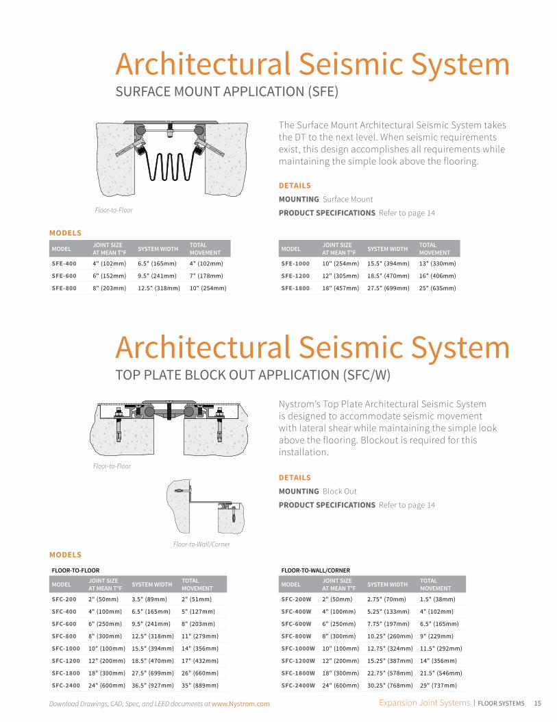
Architectural Seismic SystemSURFACE MOUNT APPLICATION (SFE)
Architectural Seismic SystemTOP PLATE BLOCK OUT APPLICATION (SFC/W)
The Surface Mount Architectural Seismic System takes the DT to the next level. When seismic requirements exist, this design accomplishes all requirements while maintaining the simple look above the flooring.
Nystrom’s Top Plate Architectural Seismic System is designed to accommodate seismic movement with lateral shear while maintaining the simple look above the flooring. Blockout is required for this installation.
Floor-to-Floor
Floor-to-Wall/Corner
Floor-to-Floor
MODELS
MODEL JOINT SIZE AT MEAN T°F SYSTEM WIDTH TOTAL
MOVEMENT
SFE-400 4" (102mm) 6.5" (165mm) 4" (102mm)
SFE-600 6" (152mm) 9.5" (241mm) 7" (178mm)
SFE-800 8" (203mm) 12.5" (318mm) 10" (254mm)
MODEL JOINT SIZE AT MEAN T°F SYSTEM WIDTH TOTAL
MOVEMENT
SFE-1000 10" (254mm) 15.5" (394mm) 13" (330mm)
SFE-1200 12" (305mm) 18.5" (470mm) 16" (406mm)
SFE-1800 18" (457mm) 27.5" (699mm) 25" (635mm)
DETAILS
MOUNTING Surface Mount
PRODUCT SPECIFICATIONS Refer to page 14
DETAILS
MOUNTING Block Out
PRODUCT SPECIFICATIONS Refer to page 14
MODELS
FLOOR-TO-FLOOR
MODEL JOINT SIZE AT MEAN T°F SYSTEM WIDTH TOTAL
MOVEMENT
SFC-200 2" (50mm) 3.5" (89mm) 2" (51mm)
SFC-400 4" (100mm) 6.5" (165mm) 5" (127mm)
SFC-600 6" (250mm) 9.5" (241mm) 8" (203mm)
SFC-800 8" (300mm) 12.5" (318mm) 11" (279mm)
SFC-1000 10" (100mm) 15.5" (394mm) 14" (356mm)
SFC-1200 12" (200mm) 18.5" (470mm) 17" (432mm)
SFC-1800 18" (300mm) 27.5" (699mm) 26" (660mm)
SFC-2400 24" (600mm) 36.5" (927mm) 35" (889mm)
FLOOR-TO-WALL/CORNER
MODEL JOINT SIZE AT MEAN T°F SYSTEM WIDTH TOTAL
MOVEMENT
SFC-200W 2" (50mm) 2.75" (70mm) 1.5" (38mm)
SFC-400W 4" (100mm) 5.25" (133mm) 4" (102mm)
SFC-600W 6" (250mm) 7.75" (197mm) 6.5" (165mm)
SFC-800W 8" (300mm) 10.25" (260mm) 9" (229mm)
SFC-1000W 10" (100mm) 12.75" (324mm) 11.5" (292mm)
SFC-1200W 12" (200mm) 15.25" (387mm) 14" (356mm)
SFC-1800W 18" (300mm) 22.75" (578mm) 21.5" (546mm)
SFC-2400W 24" (600mm) 30.25" (768mm) 29" (737mm)

Download Drawings, CAD, Spec, and LEED documents at www.Nystrom.com16
Architectural Seismic SystemRENOVATION APPLICATION (SFB)
Architectural Seismic SystemCORROSION RESISTANT APPLICATION (SFX/W)
The Renovation Seismic Expansion Joint System is designed for renovation building projects where an expansion joint is needed to tie new construction to existing construction. The system is bolted into the existing construction and a block out with back fill is necessary for the new construction.
The Stainless Steel Architectural Seismic System is designed to cover expansion control openings in structural, high movement joints, when the specification calls for a stainless steel requirement.
Floor-to-Floor
Floor-to-Wall/Corner
Floor-to-Floor
MODELS
MODEL JOINT SIZE AT MEAN T°F SYSTEM WIDTH TOTAL
MOVEMENT
SFB-400 4" (102mm) 6.5" (165mm) 5" (127mm)
SFB-600 6" (152mm) 9.5" (241mm) 8" (203mm)
SFB-800 8" (203mm) 12.5" (318mm) 11" (279mm)
MODEL JOINT SIZE AT MEAN T°F SYSTEM WIDTH TOTAL
MOVEMENT
SFB-1000 10" (254mm) 15.5" (394mm) 14" (356mm)
SFB-1200 12" (305mm) 18.5" (470mm) 17" (432mm)
SFB-1800 18" (457mm) 27.5" (699mm) 26" (660mm)
DETAILS
MOUNTING Block Out & Surface Mount
PRODUCT SPECIFICATIONS Refer to page 14
DETAILS
MATERIAL T304 Stainless Steel
MOUNTING Block Out
OPTIONS Brass
PRODUCT SPECIFICATIONS Refer to page 14
MODELS
FLOOR-TO-FLOOR
MODEL JOINT SIZE AT MEAN T°F SYSTEM WIDTH TOTAL
MOVEMENT
SFX-200 2" (50mm) 6.25" (159mm) 2" (51mm)
SFX-400 4" (100mm) 10.38" (264mm) 5" (127mm)
SFX-600 6" (250mm) 13.75" (349mm) 8" (203mm)
SFX-800 8" (300mm) 15.75" (400mm) 11" (279mm)
SFX-1000 10" (100mm) 18.75" (476mm) 14" (356mm)
SFX-1200 12" (200mm) 21.75" (552mm) 17" (432mm)
SFX-1800 18" (300mm) 31.75" (806mm) 26" (660mm)
SFX-2400 24" (600mm) 40.75" (1035mm) 35" (889mm)
FLOOR-TO-WALL/CORNER
MODEL JOINT SIZE AT MEAN T°F SYSTEM WIDTH TOTAL
MOVEMENT
SFX-200W 2" (50mm) 3.88" (99mm) 1.5" (38mm)
SFX-400W 4" (100mm) 7.19" (183mm) 4" (102mm)
SFX-600W 6" (250mm) 9.88" (251mm) 6.5" (165mm)
SFX-800W 8" (300mm) 11.88" (302mm) 9" (229mm)
SFX-1000W 10" (100mm) 14.38" (365mm) 11.5" (292mm)
SFX-1200W 12" (200mm) 16.88" (429mm) 14" (356mm)
SFX-1800W 18" (300mm) 24.88" (632mm) 21.5" (546mm)
SFX-2400W 24" (600mm) 35" (889mm) 29" (737mm)

17Download Drawings, CAD, Spec, and LEED documents at www.Nystrom.com Expansion Joint Systems | FLOOR SYSTEMS
MODELS
MODEL INSTALLATION JOINT SIZE AT MEAN T°F SYSTEM WIDTH TOTAL
MOVEMENT
NBR-100 Floor-to-Floor 1" (25mm) 2" (50mm) 2" (51mm)
NBR-100W Floor-to-Wall 1" (25mm) 1.5" (38mm) 1" (25mm)
NBR-200 Floor-to-Floor 2" (50mm) 3" (76mm) 3.75" (95mm)
NBR-200W Floor-to-Wall 2" (50mm) 2.5" (64mm) 2.25" (57mm)
NBR-300 Floor-to-Floor 3" (76mm) 4" (102mm) 3" (76mm)
NBR-300W Floor-to-Wall 3" (76mm) 3.5" (89mm) 2.25" (57mm)
NBR-400 Floor-to-Floor 4" (102mm) 5" (127mm) 4" (102mm)
NBR-400W Floor-to-Wall 4" (102mm) 4.5" (114mm) 2.25" (57mm)
Seismic Glide FLOORING INFILL SYSTEM (NBR/W)
Nystrom’s Seismic flooring infill systems is designed to accept most traditional Floor Systems and allow for multi-directional thermal movement, yet minimize the sight-line when installed.
FEATURESEASIER INSTALLATION The beveled edge relief on the extrusion virtually eliminates any need to remove concrete from the block-out.
FLOORING INFILL Designed with a recess for vinyl, carpet or tile (VCT) flooring to cover the aluminum plate and reduce the overall sight-line.
COORDINATING CORNERS Available with corner option for a complete floor solution.
DETAILS
MATERIAL 6063-T6 Aluminum
FINISH Mill
MOVEMENT • Thermal: Horizontal and Vertical• Seismic: Lateral Shear
MOUNTING Block Out
JOINT SIZE 1 inch to 4 inches
LENGTH 10 Linear Feet
APPLICATION Interior
LOAD Pedestrian and Light Cart
INSTALLATION Floor
OPTIONS Moisture Barrier, Fire Barrier
Floor-to-Floor
Floor-to-Wall/Corner

Download Drawings, CAD, Spec, and LEED documents at www.Nystrom.com18
Seismic Glide NO BUMP SYSTEM (NBF/W)
Nystrom’s Seismic Glide No Bump system is designed to allow for multi-directional thermal movement, in a durable, easily assembled cover system. The convex design allows for a smooth, no bump, transition, when light cart wheeled traffic is rolled over the system.
DETAILS
MATERIAL 6063-T6 Aluminum
FINISH Mill
MOVEMENT • Thermal: Horizontal and Vertical• Seismic: Lateral Shear
MOUNTING Block Out
JOINT SIZE 1 inch to 4 inches
LENGTH 10 Linear Feet
LOAD Pedestrian and Light Cart
INSTALLATION Floor
OPTIONS Moisture Barrier, Fire Barrier
FEATURESEASIER INSTALLATION The beveled edge relief on the extrusion virtually eliminates any need to remove con-crete from the block-out.
ANTI-SLIP SURFACE The no bump, ribbed anti-slip surface provides safe functionality for foot and cart traffic.
COORDINATING CORNERS Available with corner option for a complete floor solution.
Floor-to-Wall/Corner
Floor-to-Floor
MODELS
MODEL INSTALLATION JOINT SIZE AT MEAN T°F SYSTEM WIDTH TOTAL
MOVEMENT
NBF-100 Floor-to-Floor 1" (25mm) 3.5" (89mm) 2" (51mm)
NBF-100W Floor-to-Wall 1" (25mm) 2.25" (57mm) 1" (25mm)
NBF-200 Floor-to-Floor 2" (50mm) 4.5" (114mm) 3.75" (95mm)
NBF-200W Floor-to-Wall 2" (50mm) 3.25" (83mm) 2.25" (57mm)
NBF-300 Floor-to-Floor 3" (76mm) 7.94" (202mm) 3" (76mm)
NBF-300W Floor-to-Wall 3" (76mm) 5.5" (140mm) 2.25" (57mm)
NBF-400 Floor-to-Floor 4" (102mm) 8.94" (227mm) 4" (102mm)
NBF-400W Floor-to-Wall 4" (102mm) 6.5" (165mm) 2.25" (57mm)

19Download Drawings, CAD, Spec, and LEED documents at www.Nystrom.com Expansion Joint Systems | FLOOR SYSTEMS
Seismic Pan FLOORING SYSTEM (FLP/W)
The Seismic Pan System is commonly used for stone, terrazzo tile and concrete slabs as well as most traditional flooring materials in courtyards and walkways. It’s capable of accommodating lateral shear and multi-directional movement including vertical displacement.
FEATURESDEEP WELL PAN Designed for terrazzo tile when large sections of tile are common.
DURABLE The backfilled concrete strengthens the design for long lasting performance.
DETAILS
MATERIAL 6063-T6 Aluminum
FINISH Mill
MOVEMENT • Thermal: Horizontal and Vertical• Seismic: Lateral Shear
MOUNTING Block Out
JOINT SIZE 2 inches to 18 inches
LENGTH 10 Linear Feet
LOAD Pedestrian and Light Cart
INSTALLATION Floor
OPTIONS Moisture Barrier, Fire Barrier
Floor-to-Wall/Corner
Floor-to-Floor
MODELSFLOOR-TO-FLOOR
MODEL JOINT SIZE AT MEAN T°F SYSTEM WIDTH TOTAL
MOVEMENT
FLP-200 2" (50mm) 10.8125" (275mm) 3" (76mm)
FLP-400 4" (100mm) 12.88" (327mm) 4.75" (121mm)
FLP-600 6" (250mm) 14.88" (378mm) 7.75" (197mm)
FLP-800 8" (300mm) 18.88" (480mm) 10.75" (273mm)
FLP-1000 10" (100mm) 20.88" (530mm) 13.75" (349mm)
FLP-1200 12" (200mm) 23.88" (607mm) 16.75" (425mm)
FLP-1600 16" (300mm) 29.88" (759mm) 22.75" (578mm)
FLP-1800 18" (600mm) 34.88" (886mm) 25.75" (654mm)
FLOOR-TO-WALL/CORNER
MODEL JOINT SIZE AT MEAN T°F SYSTEM WIDTH TOTAL
MOVEMENT
FLP-200W 2" (50mm) 6.4375" (164mm) 1.375" (35mm)
FLP-400W 4" (100mm) 8.44" (214mm) 3" (76mm)
FLP-600W 6" (250mm) 10.44" (265mm) 5.5" (140mm)
FLP-800W 8" (300mm) 13.44" (341mm) 8" (203mm)
FLP-1000W 10" (100mm) 15.44" (392mm) 10.5" (267mm)
FLP-1200W 12" (200mm) 17.94" (456mm) 13" (330mm)
FLP-1600W 16" (300mm) 22.94" (583mm) 18" (457mm)
FLP-1800W 18" (600mm) 26.44" (672mm) 20.5" (521mm)
Download Drawings, CAD, Spec, and LEED documents at www.Nystrom.com20
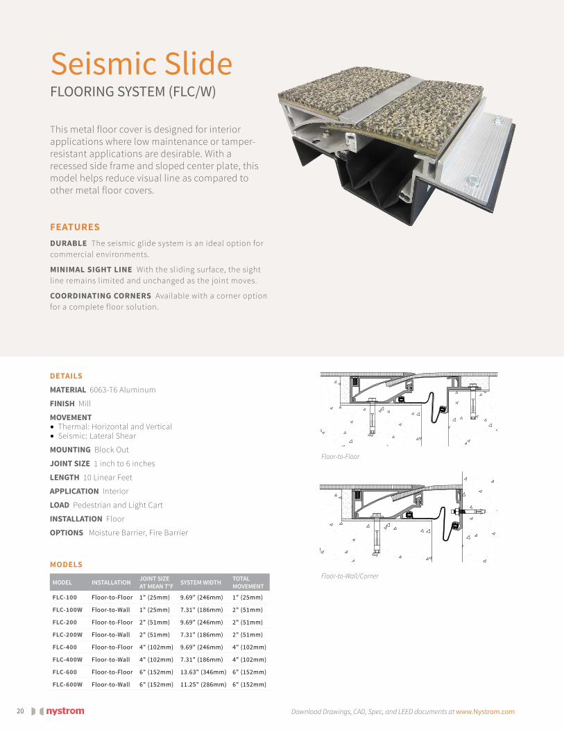
Seismic Slide FLOORING SYSTEM (FLC/W)
This metal floor cover is designed for interior applications where low maintenance or tamper-resistant applications are desirable. With a recessed side frame and sloped center plate, this model helps reduce visual line as compared to other metal floor covers.
DETAILS
MATERIAL 6063-T6 Aluminum
FINISH Mill
MOVEMENT • Thermal: Horizontal and Vertical• Seismic: Lateral Shear
MOUNTING Block Out
JOINT SIZE 1 inch to 6 inches
LENGTH 10 Linear Feet
APPLICATION Interior
LOAD Pedestrian and Light Cart
INSTALLATION Floor
OPTIONS Moisture Barrier, Fire Barrier
FEATURESDURABLE The seismic glide system is an ideal option for commercial environments.
MINIMAL SIGHT LINE With the sliding surface, the sight line remains limited and unchanged as the joint moves.
COORDINATING CORNERS Available with a corner option for a complete floor solution.
Floor-to-Wall/Corner
Floor-to-Floor
MODELS
MODEL INSTALLATION JOINT SIZE AT MEAN T°F SYSTEM WIDTH TOTAL
MOVEMENT
FLC-100 Floor-to-Floor 1" (25mm) 9.69" (246mm) 1" (25mm)
FLC-100W Floor-to-Wall 1" (25mm) 7.31" (186mm) 2" (51mm)
FLC-200 Floor-to-Floor 2" (51mm) 9.69" (246mm) 2" (51mm)
FLC-200W Floor-to-Wall 2" (51mm) 7.31" (186mm) 2" (51mm)
FLC-400 Floor-to-Floor 4" (102mm) 9.69" (246mm) 4" (102mm)
FLC-400W Floor-to-Wall 4" (102mm) 7.31" (186mm) 4" (102mm)
FLC-600 Floor-to-Floor 6" (152mm) 13.63" (346mm) 6" (152mm)
FLC-600W Floor-to-Wall 6" (152mm) 11.25" (286mm) 6" (152mm)

21Download Drawings, CAD, Spec, and LEED documents at www.Nystrom.com Expansion Joint Systems | WALL & CEILING SYSTEMS
Aluminum WALL & CEILING SYSTEM (WJ/W)
Nystrom’s Aluminum Wall and Ceiling system is capable of thermal movement. It mounts easily after final wall surface is complete. Standard with a clear anodize finish.
FEATURESCOORDINATING CORNERS Available with corner option for a complete solution.
ARCHITECTURAL AESTHETICS The sliding cover plate with a clear anodized finish provides a high-end appearance.
CONTINUOUS SIGHT LINE This system can be used on walls, ceilings and corners to provide seamless and continuous aesthetics.
DETAILS
MATERIAL 6063-T6 Aluminum
FINISH Clear Anodize
MOVEMENT • Thermal: Horizontal
MOUNTING Surface
JOINT SIZE 1 inch to 3 inches
LENGTH 10 Linear Feet
APPLICATION Interior
INSTALLATION Wall or Ceiling
OPTIONS Moisture Barrier, Fire Barrier
Wall/Ceiling Corner
Wall-to-Wall
MODELS
MODEL INSTALLATION JOINT SIZE AT MEAN T°F SYSTEM WIDTH TOTAL
MOVEMENT
WJ-100 Wall-to-Wall 1" (25mm) 3" (76mm) 0.5" (13mm)
WJ-100W Wall-to-Ceiling/Corner 1" (25mm) 3" (76mm) 0.5" (13mm)
WJ-150 Wall-to-Wall 1.5" (38mm) 4" (102mm) 2" (51mm)
WJ-200 Wall-to-Wall 2" (51mm) 5.75" (146mm) 2" (51mm)
WJ-200W Wall-to-Ceiling/Corner 2" (51mm) 5.75" (146mm) 2" (51mm)
WJ-300 Wall-to-Wall 3" (76mm) 7" (178mm) 3" (76mm)
WJ-300W Wall-to-Ceiling/Corner 3" (76mm) 7" (178mm) 3" (76mm)
Download Drawings, CAD, Spec, and LEED documents at www.Nystrom.com22
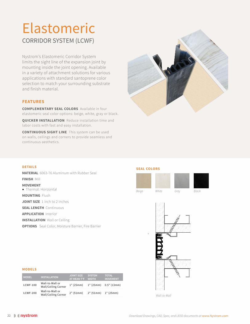
Elastomeric CORRIDOR SYSTEM (LCWF)
Nystrom’s Elastomeric Corridor System limits the sight line of the expansion joint by mounting inside the joint opening. Available in a variety of attachment solutions for various applications with standard santoprene color selection to match your surrounding substrate and finish material.
DETAILS
MATERIAL 6063-T6 Aluminum with Rubber Seal
FINISH Mill
MOVEMENT • Thermal: Horizontal
MOUNTING Flush
JOINT SIZE 1 inch to 2 inches
SEAL LENGTH Continuous
APPLICATION Interior
INSTALLATION Wall or Ceiling
OPTIONS Seal Color, Moisture Barrier, Fire Barrier
FEATURESCOMPLEMENTARY SEAL COLORS Available in four elastomeric seal color options: beige, white, gray or black.
QUICKER INSTALLATION Reduce installation time and labor costs with fast and easy installation.
CONTINUOUS SIGHT LINE This system can be used on walls, ceilings and corners to provide seamless and continuous aesthetics.
Wall-to-Wall
MODELS
MODEL INSTALLATION JOINT SIZE AT MEAN T°F
SYSTEM WIDTH
TOTAL MOVEMENT
LCWF-100 Wall-to-Wall or Wall/Ceiling Corner 1" (25mm) 1" (25mm) 0.5" (13mm)
LCWF-200 Wall-to-Wall or Wall/Ceiling Corner 2" (51mm) 2" (51mm) 1" (25mm)
SEAL COLORS
Beige GrayWhite Black
23Download Drawings, CAD, Spec, and LEED documents at www.Nystrom.com Expansion Joint Systems | WALL & CEILING SYSTEMS
Wall-to-Wall Wall/Ceiling Corner
See page 25 for similar seismic product. LCD
Wall/Ceiling Corner
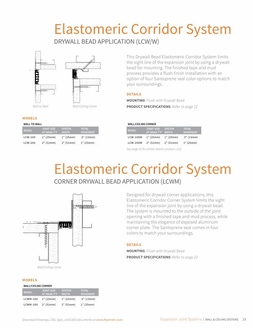
Elastomeric Corridor SystemDRYWALL BEAD APPLICATION (LCW/W)
Elastomeric Corridor SystemCORNER DRYWALL BEAD APPLICATION (LCWM)
This Drywall Bead Elastomeric Corridor System limits the sight line of the expansion joint by using a drywall bead for mounting. The finished tape and mud process provides a flush finish installation with an option of four Santoprene seal color options to match your surroundings.
Designed for drywall corner applications, this Elastomeric Corridor Corner System limits the sight line of the expansion joint by using a drywall bead. The system is mounted to the outside of the joint opening with a finished tape and mud process, while maintaining the elegance of exposed aluminum corner plate. The Santoprene seal comes in four colors to match your surroundings.
MODELS
MODELS
DETAILS
MOUNTING Flush with Drywall Bead
PRODUCT SPECIFICATIONS Refer to page 22
DETAILS
MOUNTING Flush with Drywall Bead
PRODUCT SPECIFICATIONS Refer to page 22
WALL-TO-WALL
MODEL JOINT SIZE AT MEAN T°F
SYSTEM WIDTH
TOTAL MOVEMENT
LCW-100 1" (25mm) 1" (25mm) .5" (13mm)
LCW-200 2" (51mm) 2" (51mm) 1" (25mm)
WALL/CEILING CORNER
MODEL JOINT SIZE AT MEAN T°F
SYSTEM WIDTH
TOTAL MOVEMENT
LCWM-100 1" (25mm) 1" (25mm) .5" (13mm)
LCWM-200 2" (51mm) 2" (51mm) 1" (25mm)
WALL/CEILING CORNER
MODEL JOINT SIZE AT MEAN T°F
SYSTEM WIDTH
TOTAL MOVEMENT
LCW-100W 1" (25mm) 1" (25mm) .5" (13mm)
LCW-200W 2" (51mm) 2" (51mm) 1" (25mm)

Download Drawings, CAD, Spec, and LEED documents at www.Nystrom.com24
Seismic Elastomeric CORRIDOR SYSTEM (LCH)
Nystrom’s Seismic Elastomeric Corridor System is a system dedicated to limiting the sight line of the expansion joint by mounting inside the joint opening, and allows a color selection to match your surrounding substrate and finish material. This system accommodates seismic movement.
DETAILS
MATERIAL 6063-T6 Aluminum with Rubber Seal
FINISH Mill
MOVEMENT • Thermal: Horizontal and Vertical• Seismic: Lateral Shear
MOUNTING Flush
JOINT SIZE 1 inch to 6 inches
SEAL LENGTH Continuous
APPLICATION Interior
INSTALLATION Wall or Ceiling
OPTIONS Seal Color
FEATURESMAXIMUM MOVEMENT Deep “V” design allows for maximum thermal and seismic movement.
COMPLEMENTARY SEAL COLORS Available in four elastomeric seal color options: beige, white, gray or black.
CONTINUOUS SIGHT LINE This system can be used on walls, ceilings and corners to provide seamless and continuous aesthetics.
Wall/Ceiling Corner
MODELS
MODEL INSTALLATION JOINT SIZE AT MEAN T°F
SYSTEM WIDTH
TOTAL MOVEMENT
LCH-100 Wall-to-Wall or Wall/Ceiling Corner 1" (25mm) 1" (25mm) 0.5" (13mm)
LCH-200 Wall-to-Wall or Wall/Ceiling Corner 2" (51mm) 2" (51mm) 2" (51mm)
LCH-300 Wall-to-Wall or Wall/Ceiling Corner 3" (76mm) 3" (76mm) 3" (76mm)
LCH-400 Wall-to-Wall or Wall/Ceiling Corner 4" (102mm) 4" (102mm) 4" (102mm)
LCH-500 Wall-to-Wall or Wall/Ceiling Corner 5" (127mm) 5" (127mm) 5" (127mm)
LCH-600 Wall-to-Wall or Wall/Ceiling Corner 6" (152mm) 6" (152mm) 6" (152mm)
SEAL COLORS
Beige GrayWhite Black

25Download Drawings, CAD, Spec, and LEED documents at www.Nystrom.com Expansion Joint Systems | WALL & CEILING SYSTEMS
Seismic Elastomeric DRYWALL SYSTEM (LCD)
This Seismic Elastomeric Drywall System limits the sight line of the expansion joint by using a drywall bead to mount the system outside the joint opening with a finished tape and mud process. The finished Santoprene seal comes in four colors to match your surrounding substrate and finish material. This system accommodates seismic movement.
FEATURESMAXIMUM MOVEMENT Deep “V” design allows for maximum thermal and seismic movement.
DRYWALL BEAD FLANGE Designed for drywall applications with punched holes for easy mounting. Mud is floated overtop of flange and easily painted leaving only the seal exposed.
COMPLEMENTARY SEAL COLORS Available in four elastomeric seal color options: beige, white, gray or black.
DETAILS
MATERIAL 6063-T6 Aluminum with Rubber Seal
FINISH Mill
MOVEMENT • Thermal: Horizontal and Vertical• Seismic: Lateral Shear
MOUNTING Flush with drywall bead
JOINT SIZE 1 inch to 6 inches
SEAL LENGTH Continuous
APPLICATION Interior
INSTALLATION Wall or Ceiling
OPTIONS Seal Color
Wall/Ceiling CornerWall-to-Wall
SEAL COLORS
Beige GrayWhite Black
MODELS
MODEL INSTALLATION JOINT SIZE AT MEAN T°F
SYSTEM WIDTH
TOTAL MOVEMENT
LCD-100 Wall-to-Wall 1" (25mm) 1" (25mm) 0.5" (13mm)
LCD-100W Wall/Ceiling Corner 1" (25mm) 1" (25mm) 0.5" (13mm)
LCD-200 Wall-to-Wall 2" (51mm) 2" (51mm) 2" (51mm)
LCD-200W Wall/Ceiling Corner 2" (51mm) 2" (51mm) 2" (51mm)
LCD-300 Wall-to-Wall 3" (76mm) 3" (76mm) 3" (76mm)
LCD-300W Wall/Ceiling Corner 3" (76mm) 3" (76mm) 3" (76mm)
MODEL INSTALLATION JOINT SIZE AT MEAN T°F
SYSTEM WIDTH
TOTAL MOVEMENT
LCD-400 Wall-to-Wall 4" (102mm) 4" (102mm) 4" (102mm)
LCD-400W Wall/Ceiling Corner 4" (102mm) 4" (102mm) 4" (102mm)
LCD-500 Wall-to-Wall 5" (127mm) 5" (127mm) 5" (127mm)
LCD-500W Wall/Ceiling Corner 5" (127mm) 5" (127mm) 5" (127mm)
LCD-600 Wall-to-Wall 6" (152mm) 6" (152mm) 6" (152mm)
LCD-600W Wall/Ceiling Corner 6" (152mm) 6" (152mm) 6" (152mm)

Download Drawings, CAD, Spec, and LEED documents at www.Nystrom.com26
Elastomeric Acoustical CEILING SYSTEM (LCA)
This Elastomeric Acoustical Ceiling System limits the sight line of the expansion joint by using an aluminum channel that attaches to the grid system above the sight line. The finished Santoprene seal comes in four colors to match your surrounding substrate and finish material.
DETAILS
MATERIAL 6063-T6 Aluminum with Rubber Seal
FINISH Mill
MOVEMENT • Thermal: Horizontal
MOUNTING Flush - Suspended
JOINT SIZE 1 inch to 2 inches
SEAL LENGTH Continuous
APPLICATION Interior
INSTALLATION Ceiling
OPTIONS Seal Color
FEATURESACOUSTIC CEILING Fully integrated with suspended ceiling grid system.
COMPLEMENTARY SEAL COLORS Available in four elastomeric seal color options: beige, white, gray or black.
CONTINUOUS SIGHT LINE This system can be used on walls, ceilings and corners to provide seamless and continuous aesthetics.
Ceiling-to-Ceiling
Ceiling Corner
MODELS
MODEL INSTALLATION JOINT SIZE AT MEAN T°F
SYSTEM WIDTH
TOTAL MOVEMENT
LCA-100 Ceiling-to-Ceiling 1" (25mm) 1" (25mm) 0.5" (13mm)
LCA-100W Ceiling Corner 1" (25mm) 1" (25mm) 0.5" (13mm)
LCA-200 Ceiling-to-Ceiling 2" (51mm) 2" (51mm) 1" (25mm)
LCA-200W Ceiling Corner 2" (51mm) 2" (51mm) 1" (25mm)
SEAL COLORS
Beige GrayWhite Black

27Download Drawings, CAD, Spec, and LEED documents at www.Nystrom.com Expansion Joint Systems | WALL & CEILING SYSTEMS
Seismic Elastomeric CEILING SYSTEM (LCE/W)
Nystrom’s Seismic Elastomeric Ceiling System uses an aluminum channel attached to the grid system above the sight line. The finished Santoprene seal comes in four colors to match your surrounding substrate and finish material. This system accommodates seismic movement.
FEATURESACOUSTIC CEILING Fully integrated with suspended ceiling grid system.
MAXIMUM MOVEMENT Deep “V” design allows for maximum thermal and seismic movement.
COMPLEMENTARY SEAL COLORS Available in four elastomeric seal color options: beige, white, gray or black.
DETAILS
MATERIAL 6063-T6 Aluminum with Rubber Seal
FINISH Mill
MOVEMENT • Thermal: Horizontal and Vertical• Seismic: Lateral Shear
MOUNTING Flush - Suspended
JOINT SIZE 1 inch to 6 inches
SEAL LENGTH Continuous
APPLICATION Interior
INSTALLATION Ceiling
OPTIONS Seal Color
Ceiling CornerCeiling-to-Ceiling
SEAL COLORS
Beige GrayWhite Black
MODELS
MODEL INSTALLATION JOINT SIZE AT MEAN T°F
SYSTEM WIDTH
TOTAL MOVEMENT
LCE-100 Ceiling-to-Ceiling 1" (25mm) 0.75" (19mm) 0.5" (13mm)
LCE-100W Ceiling Corner 1" (25mm) 0.75" (19mm) 0.5" (13mm)
LCE-200 Ceiling-to-Ceiling 2" (51mm) 1.75" (44mm) 2" (51mm)
LCE-200W Ceiling Corner 2" (51mm) 1.75" (44mm) 2" (51mm)
LCE-300 Ceiling-to-Ceiling 3" (76mm) 2.75" (70mm) 3" (76mm)
LCE-300W Ceiling Corner 3" (76mm) 2.75" (70mm) 3" (76mm)
MODEL INSTALLATION JOINT SIZE AT MEAN T°F
SYSTEM WIDTH
TOTAL MOVEMENT
LCE-400 Ceiling-to-Ceiling 4" (102mm) 3.75" (95mm) 4" (102mm)
LCE-400W Ceiling Corner 4" (102mm) 3.75" (95mm) 4" (102mm)
LCE-500 Ceiling-to-Ceiling 5" (127mm) 4.75" (121mm) 5" (127mm)
LCE-500W Ceiling Corner 5" (127mm) 4.75" (121mm) 5" (127mm)
LCE-600 Ceiling-to-Ceiling 6" (152mm) 5.75" (146mm) 6" (152mm)
LCE-600W Ceiling Corner 6" (152mm) 5.75" (146mm) 6" (152mm)

Download Drawings, CAD, Spec, and LEED documents at www.Nystrom.com28
Seismic Elastomeric TWIN SEAL SYSTEM (SWNB/W)
The Seismic Elastomeric Twin Seal System offers protection of expansion joints in a seismic event. This system is constructed of two rubber seals and an aluminum slide plate. This system allows for multi-directional movement with a seismic centering bar.
DETAILS
MATERIAL 6063-T6 Aluminum with Rubber Seal
FINISH Clear Anodized
MOVEMENT • Thermal: Horizontal and Vertical• Seismic: Lateral Shear
MOUNTING Surface
JOINT SIZE 4 inches to 24 inches
LENGTH 10 Linear Feet
APPLICATION Interior
INSTALLATION Wall or Ceiling
OPTIONS Seal Color, Moisture Barrier, Fire Barrier
FEATURESSEISMIC MOVEMENT This seismic system is engineered to accept lateral shear.
COORDINATING CORNERS Available with a corner option for a completion solution.
COMPLEMENTARY SEAL COLORS Available in four elastomeric seal color options: beige, white, gray or black.
Wall-to-Wall
Wall/Ceiling Corner
SEAL COLORS
Beige GrayWhite Black
MODELSWALL-TO-WALL
MODEL JOINT SIZE AT MEAN T°F SYSTEM WIDTH TOTAL
MOVEMENT
SWNB-400 4" (102mm) 11.88" (302mm) 4" (102mm)
SWNB-600 6" (152mm) 15.88" (403mm) 7" (178mm)
SWNB-800 8" (203mm) 17.88" (454mm) 10" (254mm)
SWNB-1000 10" (254mm) 21.88" (556mm) 13" (330mm)
SWNB-1200 12" (305mm) 23.88" (606mm) 16" (406mm)
SWNB-1800 18" (305mm) 33.88" (860mm) 25" (635mm)
SWNB-2000 20" (381mm) 42.88" (1089mm) 34" (864mm)
CORNER
MODEL JOINT SIZE AT MEAN T°F SYSTEM WIDTH TOTAL
MOVEMENT
SWNB-400W 4" (102mm) 7.94" (202mm) 3.25" (83mm)
SWNB-600W 6" (152mm) 10.94" (278mm) 5.75" (146mm)
SWNB-800W 8" (203mm) 12.94" (329mm) 7.75" (197mm)
SWNB-1000W 10" (254mm) 15.94" (405mm) 11.25" (286mm)
SWNB-1200W 12" (305mm) 17.94" (456mm) 13.25" (337mm)
SWNB-1800W 18" (305mm) 25.63" (651mm) 21" (533mm)
SWNB-2000W 20" (381mm) 33.13" (841mm) 28.5" (724mm)

29Download Drawings, CAD, Spec, and LEED documents at www.Nystrom.com Expansion Joint Systems | WALL & CEILING SYSTEMS
Seismic Glide SYSTEM (NBW/W)
Nystrom’s Seismic Glide System wall and ceiling expansion control system is capable of multi directional changes, as well as integrating with a variety of wall and ceiling surface treatments. Seismic Glide is available in clear anodized aluminum to create a sleek look at an economical price.
FEATURESCOORDINATING CORNERS Available with corner option for a complete solution.
GASKETS The assembly includes a gasket strip on either side to limit air flow in the joint.
EASY ASSEMBLY After base plates are attached to the wall, the cover assembly snaps together for a tight fit.
DETAILS
MATERIAL 6063-T6 Aluminum
FINISH Clear Anodized
MOVEMENT • Thermal: Horizontal and Vertical• Seismic: Lateral Shear
MOUNTING Surface
JOINT SIZE 1 inch to 2 inches
LENGTH 10 Linear Feet
APPLICATION Interior
INSTALLATION Wall or Ceiling
OPTIONS Moisture Barrier, Fire Barrier
Wall/Ceiling Corner
Wall-to-Wall
MODELS
MODEL INSTALLATION JOINT SIZE AT MEAN T°F
SYSTEM WIDTH
TOTAL MOVEMENT
NBW-100 Wall-to-Wall 1" (25mm) 3" (76mm) 1" (25mm)
NBW-100W Corner 1" (25mm) 3" (76mm) 1" (25mm)
NBW-200 Wall-to-Wall 2" (51mm) 5" (127mm) 2" (51mm)
NBW-200W Corner 2" (51mm) 5" (127mm) 2" (51mm)

Download Drawings, CAD, Spec, and LEED documents at www.Nystrom.com30
Seismic Glide WALL XL SYSTEM (WCS/W)
The Seismic Glide Wall XL System is a wall and ceiling expansion control system capable of following complex directional changes and integrates with a variety of wall and ceiling surface treatments. Seismic Glide XL is available in clear or color anodized aluminum, brass or stainless steel to create a high end elegant appearance at an economical price.
DETAILS
MATERIAL 6063-T6 Aluminum
FINISH Clear Anodized
MOVEMENT • Thermal: Horizontal and Vertical• Seismic: Lateral Shear
MOUNTING Surface
JOINT SIZE 3 inches to 24 inches
LENGTH 10 Linear Feet
APPLICATION Interior
INSTALLATION Wall or Ceiling
OPTIONS Brass, Stainless Steel, Moisture Barrier, Fire Barrier
FEATURESEXTRA LARGE OPENINGS For openings larger than 2 inches, this system is designed to accommodate with lateral shear.
REDUCED AIR INFILTRATION The assembly includes a gasket strip on both sides to limit air flow through the joint.
Wall-to-Wall
Wall/Ceiling CornerMODELS
WALL-TO-WALL
MODEL JOINT SIZE AT MEAN T°F SYSTEM WIDTH TOTAL
MOVEMENT
WCS-300 3" (50mm) 7.56" (192mm) 4" (102mm)
WCS-400 4" (102mm) 13.63" (346mm) 7" (178mm)
WCS-600 6" (152mm) 15.63" (397mm) 7" (178mm)
WCS-800 8" (203mm) 20.75" (527mm) 8" (203mm)
WCS-1000 10" (254mm) 22.25" (565mm) 13.625" (346mm)
WCS-1200 12" (305mm) 26.25" (667mm) 16.625" (422mm)
WCS-1800 15" (381mm) 32.75" (832mm) 21.625" (549mm)
WCS-2400 18" (457mm) 38.25" (972mm) 25.625" (657mm)
CORNER
MODEL JOINT SIZE AT MEAN T°F SYSTEM WIDTH TOTAL
MOVEMENT
WCS-300W 3" (50mm) 7.25" (184mm) 3" (76mm)
WCS-400W 4" (102mm) 7.75" (197mm) 4.5" (114mm)
WCS-600W 6" (152mm) 10.75" (273mm) 4.5" (114mm)
WCS-800W 8" (203mm) 13.75" (349mm) 8" (203mm)
WCS-1000W 10" (254mm) 16.125" (410mm) 6.625" (169mm)
WCS-1200W 12" (305mm) 19.125" (486mm) 8.125" (206mm)
WCS-1800W 15" (381mm) 23.875" (606mm) 10.625" (270mm)
WCS-2400W 18" (457mm) 28.125" (714mm) 12.625" (321mm)

31Download Drawings, CAD, Spec, and LEED documents at www.Nystrom.com Expansion Joint Systems | WALL & CEILING SYSTEMS
Seismic Architectural WALL SYSTEM (FCT/W)
Nystrom’s Seismic Architectural Wall System is a wall and ceiling system designed to accommodate both thermal and multi-directional movement. The system provides a simple, attractive and durable solution for internal environments.
FEATURESSEISMIC CENTERING BAR System realigns itself with the self-centering bar, maintaining a safe, clean look.
ARCHITECTURAL ELEGANCE The clear anodized cover plate finish provides a high-end appearance.
COORDINATING CORNERS Available with corner option for a complete solution.
DETAILS
MATERIAL 6063-T6 Aluminum
FINISH Clear Anodized
MOVEMENT • Thermal: Horizontal and Vertical• Seismic: Lateral Shear
MOUNTING Surface
JOINT SIZE 4 inches to 24 inches
LENGTH 10 Linear Feet
APPLICATION Interior
INSTALLATION Wall or Ceiling
OPTIONS Brass, Stainless Steel, Moisture Barrier, Fire Barrier Wall/Ceiling Corner
Wall-to-Wall
MODELSWALL-TO-WALL
MODEL JOINT SIZE AT MEAN T°F SYSTEM WIDTH TOTAL
MOVEMENT
FCT-400 4" (102mm) 13.5" (343mm) 9.75" (248mm)
FCT-600 6" (152mm) 13.5" (343mm) 9.75" (248mm)
FCT-800 8" (203mm) 17.5" (445mm) 13.75" (349mm)
FCT-1000 10" (254mm) 21.5" (546mm) 17.25" (438mm)
FCT-1200 12" (305mm) 25.5" (648mm) 21" (533mm)
FCT-1800 18" (305mm) 37.5" (953mm) 33" (838mm)
FCT-2400 24" (610mm) 49.5" (1257mm) 45" (1143mm)
CORNER
MODEL JOINT SIZE AT MEAN T°F SYSTEM WIDTH TOTAL
MOVEMENT
FCT-400W 4" (102mm) 9.75" (248mm) 6.25" (159mm)
FCT-600W 6" (152mm) 9.75" (248mm) 6.25" (159mm)
FCT-800W 8" (203mm) 12.75" (324mm) 8.25" (210mm)
FCT-1000W 10" (254mm) 15.75" (400mm) 10.25" (260mm)
FCT-1200W 12" (305mm) 18.75" (476mm) 12.25" (311mm)
FCT-1800W 18" (305mm) 27.75" (705mm) 18.25" (464mm)
FCT-2400W 24" (610mm) 36.75" (984mm) 24.25" (616mm)

Download Drawings, CAD, Spec, and LEED documents at www.Nystrom.com32
Santoprene COMPRESSION SYSTEM (SAN)
Nystrom’s Santoprene Compression Seal has many years in the field with long lasting and durable results. The color selections match many exterior building colors. The product ships in a continuous lengths to maximum limits.
DETAILS
MATERIAL Santoprene
MOVEMENT • Thermal: Horizontal and Vertical
MOUNTING Compression
JOINT SIZE 1 inch to 6 inches
LENGTH Continuous
APPLICATION Interior or Exterior
INSTALLATION Wall or Ceiling
OPTIONS Seal Color, Fire Barrier
FEATURESCOLOR COORDINATION Available in four elastomeric seal color options: beige, white, gray or black.
WATER RESISTANT The system is designed to keep water out and dryness in.
CONTINUOUS LENGTH Product is shipped in maximum lengths to maintain a limited number of field splices.
MODELS
MODEL MINIMUMJOINT OPENING
MAXIMUMJOINT OPENING SYSTEM DEPTH
SAN-100* 0.5" (13mm) 1.5" (38mm) N/A
SAN-225 0.6875" (17mm) 1.94" (49mm) 1.88" (48mm)
SAN-250 1.06" (27mm) 2.13" (54mm) 2.38" (60mm)
SAN-300 1.44" (37mm) 2.56" (65mm) 2.53" (64mm)
SAN-400 1.25" (32mm) 3.39" (86mm) 3.19" (81mm)
SAN-500 1.44" (37mm) 4.25" (108mm) 3.63" (92mm)
SAN-600 1.81" (46mm) 5.12" (130mm) 4.63" (118mm)
SEAL COLORS
Beige GrayWhite Black
Lubricant used for installation and assembly. Request part number 4050 for every 75 feet of material.* 10 foot lengths

33Download Drawings, CAD, Spec, and LEED documents at www.Nystrom.com Expansion Joint Systems | WALL & CEILING SYSTEMS
Elastomeric EXTERIOR WALL SYSTEM (EW/EWN)
This Elastomeric Exterior Wall System is a weather tight system that accommodates thermal and seismic movement. The visual seal matches many exterior building colors and the rear moisture barrier prevents and exterior moisture or condensation from entering the wall cavity.
FEATURESCOLOR COORDINATION Available in four elastomeric seal color options: beige, white, gray or black.
WEATHER TIGHT The combination of the visual seal and moisture barrier ensures the elements are kept outside.
INTEGRATED MOISTURE BARRIER Assembly of the moisture barrier is simplified with internal logs.
DETAILS
MATERIAL 6063-T6 Aluminum
FINISH Mill
MOVEMENT • Thermal: Horizontal and Vertical• Seismic: Lateral Shear
MOUNTING Recess
JOINT SIZE 2 inches to 24 inches
LENGTH 10 Linear Feet
APPLICATION Exterior
INSTALLATION Wall
OPTIONS Seal Color, Fire Barrier
MODELS
MODEL INSTALLATION JOINT SIZE AT MEAN T°F
SYSTEM WIDTH
TOTAL MOVEMENT
EWN-200MB Wall-to-Wall 2" (51mm) 2" (51mm) 2.63" (67mm)
EWN-300MB Wall-to-Wall 3" (76mm) 3" (76mm) 5.13" (130mm)
EWN-400MB Wall-to-Wall 4" (102mm) 4" (102mm) 4.75" (121mm)
EWN-500MB Wall-to-Wall 5" (127mm) 5" (127mm) 6.75" (171mm)
EWN-600MB Wall-to-Wall 6" (152mm) 6" (152mm) 9.5" (241mm)
EW-800MB Wall-to-Wall 8" (203mm) 8" (203mm) 9.63" (245mm)
EW-900MB Wall-to-Wall 9" (229mm) 9" (229mm) 15.38" (391mm)
MODEL INSTALLATION JOINT SIZE AT MEAN T°F
SYSTEM WIDTH
TOTAL MOVEMENT
EW-1000MB Wall-to-Wall 10" (254mm) 10" (254mm) 13.63" (346mm)
EW-1200MB Wall-to-Wall 12" (305mm) 12" (305mm) 19.13" (486mm)
EW-1500MB Wall-to-Wall 15" (381mm) 15" (381mm) 20.25" (514mm)
EW-1600MB Wall-to-Wall 16" (406mm) 16" (406mm) 19" (483mm)
EW-1800MB Wall-to-Wall 18" (457mm) 18" (457mm) 28.5" (724mm)
EW-2000MB Wall-to-Wall 20" (508mm) 20" (508mm) 27" (686mm)
EW-2400MB Wall-to-Wall 24" (610mm) 24" (610mm) 38" (965mm)
SEAL COLORS
Beige GrayWhite Black

Download Drawings, CAD, Spec, and LEED documents at www.Nystrom.com34
Seismic Security EXTERIOR WALL SYSTEM (RJX/W)
The seismic security exterior application provides an aluminum cover plate for security and includes a moisture barrier for added water and air protection.
DETAILS
MATERIAL 6063-T6 Aluminum
FINISH Clear Anodized
MOVEMENT • Thermal: Horizontal and Vertical• Seismic: Lateral Shear
MOUNTING Surface
JOINT SIZE 6 inches to 24 inches
LENGTH 10 Linear Feet
APPLICATION Interior or Exterior
INSTALLATION Wall or Ceiling
OPTIONS Brass, Stainless Steel, Fire Barrier
FEATURESSEISMIC MOVEMENT System realigns itself with the self-centering bar, maintaining a safe, clean look.
WEATHER TIGHT The integrated moisture barrier will keep the elements out and the comfort in.
ARCHITECTURAL ELEGANCE The clear anodized cover plate finish provides a high-end appearance.
Wall-to-Wall
Wall/Ceiling Corner
MODELSWALL-TO-WALL
MODEL JOINT SIZE AT MEAN T°F SYSTEM WIDTH TOTAL
MOVEMENT
RJX-600 6" (25mm) 13.5" (343mm) 9.75" (248mm)
RJX-800 8" (51mm) 17.5" (445mm) 13.75" (349mm)
RJX-1000 10" (76mm) 21.5" (546mm) 17.25" (438mm)
RJX-1200 12" (305mm) 25.5" (648mm) 21" (533mm)
RJX-1800 18" (457mm) 37.5" (953mm) 33" (838mm)
RJX-2400 24" (610mm) 49.5" (1257mm) 45" (1143mm)
CORNER
MODEL JOINT SIZE AT MEAN T°F SYSTEM WIDTH TOTAL
MOVEMENT
RJX-600W 6" (25mm) 9.75" (248mm) 6.25" (159mm)
RJX-800W 8" (51mm) 12.75" (324mm) 8.25" (210mm)
RJX-1000W 10" (254mm) 15.75" (400mm) 10.25" (260mm)
RJX-1200W 12" (305mm) 18.75" (476mm) 12.25" (311mm)
RJX-1800W 18" (457mm) 27.75" (705mm) 18.25" (434mm)
RJX-2400W 24" (610mm) 36.75" (984mm) 24.25" (616mm)

35Download Drawings, CAD, Spec, and LEED documents at www.Nystrom.com Expansion Joint Systems | ROOF SYSTEMS
Roof Deck Roof Deck
Roof Deck
Roof Bellow SYSTEM (EEJ/W & ECF/W)
Nystrom’s Roof Bellows System is an effective, flexible joint closure for a wide variety of standard and special applications. The EEJ and ECF covers are 60-mil thick, reinforced EPDM bellows widely used in roof to roof and roof to wall cant or curb applications.
FEATURESEASY TRANSITIONS Water and weather tight factory manufactured transitions available.
FLANGE STYLE Flange is available in galvanized steel, copper, stainless steel and aluminum.
OPTIONAL CURB APPLICATION Specify model ECF for flat roof systems when a curb is required.
DETAILS
MATERIAL EPDM Bellows w/Galvanized Steel Flange
MOVEMENT • Thermal: Horizontal and Vertical• Seismic: Lateral Shear
MOUNTING Surface
JOINT SIZE 1 inch to 20 inches
LENGTH 10 Linear Feet, 50 Linear Feet or 100 Linear Feet
APPLICATION Exterior
INSTALLATION Roof
Roof-to-RoofRoof-to-Soffit
MODELSROOF-TO-ROOFMODEL CANT
MODEL CURB
JOINT SIZE AT MEAN T°F
EEJ-100 ECF-100 1" (25mm)
EEJ-200 ECF-200 2" (51mm)
EEJ-300 ECF-300 3" (76mm)
EEJ-400 ECF-400 4" (102mm)
EEJ-500 ECF-500 5" (127mm)
EEJ-600 ECF-600 6" (152mm)
EEJ-700 ECF-700 7" (178mm)
ROOF-TO-WALLMODEL CANT
MODEL CURB
JOINT SIZE AT MEAN T°F
EEJ-100W ECF-100W 1" (25mm)
EEJ-200W ECF-200W 2" (51mm)
EEJ-300W ECF-300W 3" (76mm)
EEJ-400W ECF-400W 4" (102mm)
EEJ-500W ECF-500W 5" (127mm)
EEJ-600W ECF-600W 6" (152mm)
EEJ-700W ECF-700W 7" (178mm)
MODEL CANT
MODEL CURB
JOINT SIZE AT MEAN T°F
EEJ-800 ECF-800 8" (203mm)
EEJ-1000 ECF-1000 10" (254mm)
EEJ-1200 ECF-1200 12" (305mm)
EEJ-1600 ECF-1600 16" (406mm)
EEJ-1800 ECF-1800 18" (457mm)
EEJ-2000 ECF-2000 20" (508mm)
MODEL CANT MODEL CURB
JOINT SIZE AT MEAN T°F
EEJ-800W ECF-800W 8" (203mm)
EEJ-1000W ECF-1000W 10" (254mm)
EEJ-1200W ECF-1200W 12" (305mm)
EEJ-1600W ECF-1600W 16" (406mm)
EEJ-1800W ECF-1800W 18" (457mm)
EEJ-2000W ECF-2000W 20" (508mm)
PROFILES
CantRoof-to-Roof
CantRoof-to-Wall
CurbRoof-to-Roof
CurbRoof-to-Wall

Download Drawings, CAD, Spec, and LEED documents at www.Nystrom.com36
ROOF DECK
WALL
ROOF DECK ROOF DECK
Roof Continuous CURB BELLOW SYSTEM (EWCF/W)
Nystrom’s Continuous Roof Curb Bellows System is an effective, flexible joint closure for a wide variety of standard and special applications. The system is designed for a continuous length for limited or no splices along the joint. The EWCF covers are 60-mil thick, reinforced EPDM bellows widely used in curb to curb applications.
DETAILS
MATERIAL EPDM Membrane
MOVEMENT• Thermal: Horizontal and Vertical• Seismic: Lateral Shear
MOUNTING Surface
JOINT SIZE 1 inch to 20 inches
LENGTH 50 or 100 Linear Foot Roll
APPLICATION Exterior
INSTALLATION Roof
FEATURESCURB APPLICATION Designed for flat roof systems when a curb is required.
CONTINUOUS LENGTH For straight runs, up to 100 linear feet, no splices are required. Eliminates opportunities for water leaks at splice points.
EASY TRANSITIONS Water and weather tight factory manufactured transitions available.
Roof-to-Roof
Roof-to-WallMODELS
ROOF-TO-ROOF
MODEL JOINT SIZE AT MEAN T°F
EWCF-100 1" (25mm)
EWCF-200 2" (51mm)
EWCF-300 3" (76mm)
EWCF-400 4" (102mm)
EWCF-500 5" (127mm)
EWCF-600 6" (152mm)
EWCF-700 7" (178mm)
ROOF-TO-WALL
MODEL JOINT SIZE AT MEAN T°F
EWCF-100W 1" (25mm)
EWCF-200W 2" (51mm)
EWCF-300W 3" (76mm)
EWCF-400W 4" (102mm)
EWCF-500W 5" (127mm)
EWCF-600W 6" (152mm)
EWCF-700W 7" (178mm)
MODEL JOINT SIZE AT MEAN T°F
EWCF-800 8" (203mm)
EWCF-1000 10" (254mm)
EWCF-1200 12" (305mm)
EWCF-1600 16" (406mm)
EWCF-1800 18" (457mm)
EWCF-2000 20" (508mm)
MODEL JOINT SIZE AT MEAN T°F
EWCF-800W 8" (203mm)
EWCF-1000W 10" (254mm)
EWCF-1200W 12" (305mm)
EWCF-1600W 16" (406mm)
EWCF-1800W 18" (457mm)
EWCF-2000W 20" (508mm)
37Download Drawings, CAD, Spec, and LEED documents at www.Nystrom.com Expansion Joint Systems | ROOF SYSTEMS
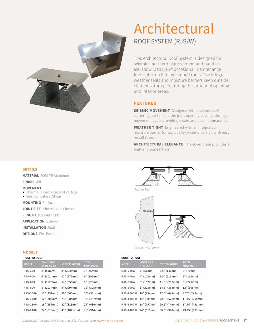
ArchitecturalROOF SYSTEM (RJS/W)
This Architectural Roof System is designed for seismic and thermal movement and handles ice, snow loads, and occasional maintenance foot traffic on flat and sloped roofs. The integral weather seals and moisture barriers keep outside elements from penetrating the structural opening and interior areas.
FEATURESSEISMIC MOVEMENT Designed with a seismic self-centering bar to keep the joint opening covered during a movement cycle providing a safe and clean appearance.
WEATHER TIGHT Engineered with an integrated moisture barrier for top quality water diversion with easy installation.
ARCHITECTURAL ELEGANCE The cover plate provides a high-end appearance.
DETAILS
MATERIAL 6063-T6 Aluminum
FINISH Mill
MOVEMENT • Thermal: Horizontal and Vertical• Seismic: Lateral Shear
MOUNTING Surface
JOINT SIZE 2 inches to 24 inches
LENGTH 10 Linear Feet
APPLICATION Exterior
INSTALLATION Roof
OPTIONS Fire Barrier
Roof-to-Roof
Roof-to-Wall CornerMODELSROOF-TO-ROOF
MODEL JOINT SIZE AT MEAN T°F SYSTEM WIDTH TOTAL
MOVEMENT
RJS-200 2" (51mm) 8" (203mm) 3" (76mm)
RJS-400 4" (102mm) 11" (279mm) 6" (152mm)
RJS-600 6" (152mm) 14" (356mm) 9" (229mm)
RJS-800 8" (203mm) 9" (229mm) 12" (305mm)
RJS-1000 10" (254mm) 20" (508mm) 15" (381mm)
RJS-1200 12" (305mm) 23" (584mm) 18" (457mm)
RJS-1800 18" (457mm) 32" (813mm) 27" (686mm)
RJS-2400 24" (610mm) 41" (1041mm) 36" (914mm)
ROOF-TO-ROOF
MODEL JOINT SIZE AT MEAN T°F SYSTEM WIDTH TOTAL
MOVEMENT
RJS-200W 2" (51mm) 5.5" (140mm) 3" (76mm)
RJS-400W 4" (102mm) 8.5" (216mm) 6" (152mm)
RJS-600W 6" (152mm) 11.5" (292mm) 9" (229mm)
RJS-800W 8" (203mm) 14.5" (368mm) 12" (305mm)
RJS-1000W 10" (254mm) 17.5" (445mm) 9.75" (248mm)
RJS-1200W 12" (305mm) 20.5" (521mm) 11.75" (298mm)
RJS-1800W 18" (457mm) 29.5" (749mm) 17.75" (451mm)
RJS-2400W 24" (610mm) 38.5" (978mm) 23.75" (603mm)

Download Drawings, CAD, Spec, and LEED documents at www.Nystrom.com38
Architectural ROOF CURB SYSTEM (RJF/W)
Nystrom’s Architectural Roof Curb System is designed to handle ice, snow loads, and occasional maintenance foot traffic. Integral weather seals and moisture barriers keep outside elements from penetrating the structural opening and interior areas. This is an all aluminum system engineered for flat and sloped roofs that are subject to thermal and seismic movement.
DETAILS
MATERIAL 6063-T6 Aluminum
FINISH Mill
MOVEMENT• Thermal: Horizontal and Vertical• Seismic: Lateral Shear
MOUNTING Surface
JOINT SIZE 6 inches to 24 inches
LENGTH 10 Linear Feet
APPLICATION Exterior
INSTALLATION Roof
OPTIONS Fire Barrier
FEATURESINTEGRATED FLASHING System includes integrated flashing for assembly before membrane is installed.
SEISMIC MOVEMENT Designed with a seismic self-centering bar to keep the joint opening covered during a movement cycle providing a safe and clean appearance.
MOISTURE BARRIER Engineered with an integrated moisture barrier for water diversion with easy installation.
Roof-to-Roof
Roof-to-Wall Corner
MODELSROOF-TO-ROOF
MODEL JOINT SIZE AT MEAN T°F SYSTEM WIDTH TOTAL
MOVEMENT
RJF-200 2" (51mm) 8" (203mm) 3" (76mm)
RJF-400 4" (102mm) 11" (279mm) 6" (152mm)
RJF-600 6" (152mm) 14" (356mm) 9" (229mm)
RJF-800 8" (203mm) 9" (229mm) 12" (305mm)
RJF-1000 10" (254mm) 20" (508mm) 15" (381mm)
RJF-1200 12" (305mm) 23" (584mm) 18" (457mm)
RJF-1800 18" (457mm) 32" (813mm) 27" (686mm)
RJF-2400 24" (610mm) 41" (1041mm) 36" (914mm)
ROOF-TO-WALL
MODEL JOINT SIZE AT MEAN T°F SYSTEM WIDTH TOTAL
MOVEMENT
RJF-200W 2" (51mm) 5.5" (140mm) 3" (76mm)
RJF-400W 4" (102mm) 8.5" (216mm) 6" (152mm)
RJF-600W 6" (152mm) 11.5" (292mm) 9" (229mm)
RJF-800W 8" (203mm) 14.5" (368mm) 12" (305mm)
RJF-1000W 10" (254mm) 17.5" (445mm) 9.75" (248mm)
RJF-1200W 12" (305mm) 20.5" (521mm) 11.75" (298mm)
RJF-1800W 18" (457mm) 29.5" (749mm) 17.75" (451mm)
RJF-2400W 24" (610mm) 38.5" (978mm) 23.75" (603mm)
39Download Drawings, CAD, Spec, and LEED documents at www.Nystrom.com Expansion Joint Systems | ROOF SYSTEMS
B
Anchor Fire barrier (if required)A
EPDM (optional)
B
EPDM (optional) Fire barrier (if required)
Fastener(by installers)
A
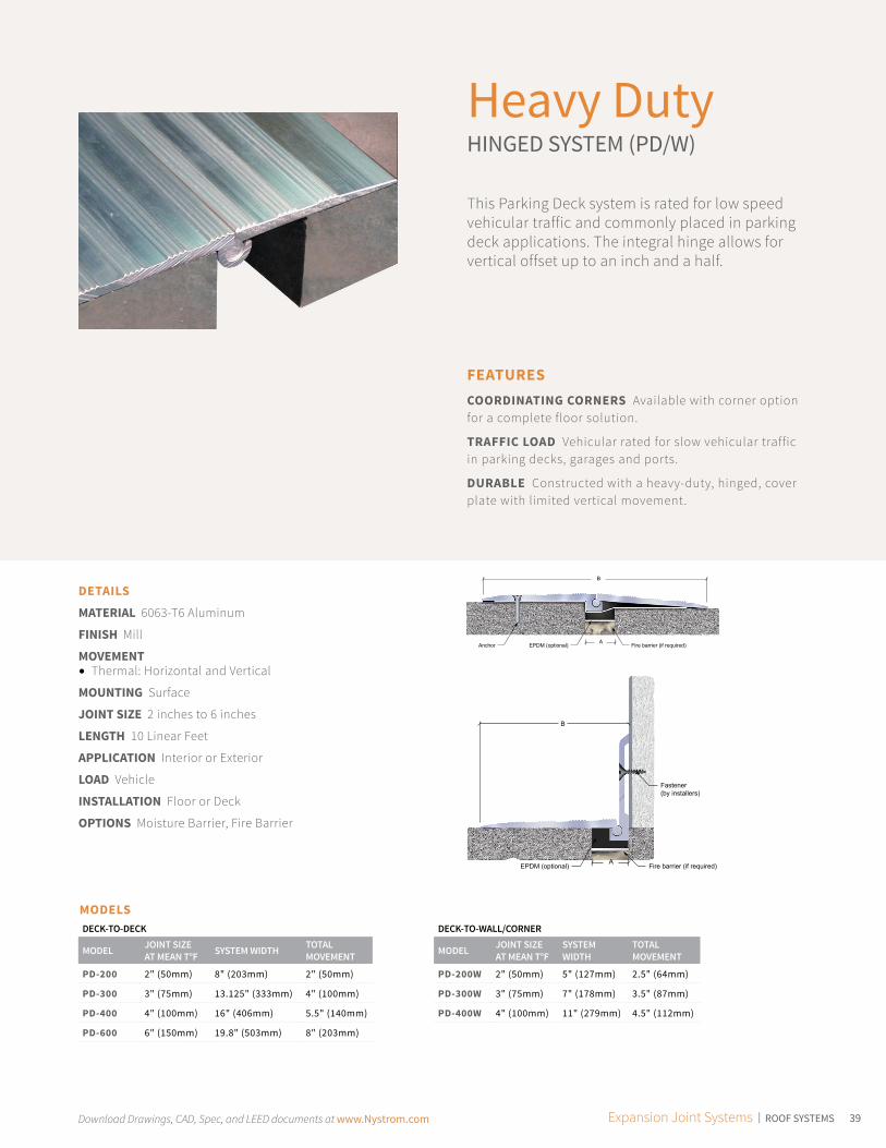
Heavy DutyHINGED SYSTEM (PD/W)
This Parking Deck system is rated for low speed vehicular traffic and commonly placed in parking deck applications. The integral hinge allows for vertical offset up to an inch and a half.
FEATURESCOORDINATING CORNERS Available with corner option for a complete floor solution.
TRAFFIC LOAD Vehicular rated for slow vehicular traffic in parking decks, garages and ports.
DURABLE Constructed with a heavy-duty, hinged, cover plate with limited vertical movement.
DETAILS
MATERIAL 6063-T6 Aluminum
FINISH Mill
MOVEMENT • Thermal: Horizontal and Vertical
MOUNTING Surface
JOINT SIZE 2 inches to 6 inches
LENGTH 10 Linear Feet
APPLICATION Interior or Exterior
LOAD Vehicle
INSTALLATION Floor or Deck
OPTIONS Moisture Barrier, Fire Barrier
MODELSDECK-TO-DECK
MODEL JOINT SIZE AT MEAN T°F SYSTEM WIDTH TOTAL
MOVEMENT
PD-200 2" (50mm) 8" (203mm) 2" (50mm)
PD-300 3" (75mm) 13.125" (333mm) 4" (100mm)
PD-400 4" (100mm) 16" (406mm) 5.5" (140mm)
PD-600 6" (150mm) 19.8" (503mm) 8" (203mm)
DECK-TO-WALL/CORNER
MODEL JOINT SIZE AT MEAN T°F
SYSTEM WIDTH
TOTAL MOVEMENT
PD-200W 2" (50mm) 5" (127mm) 2.5" (64mm)
PD-300W 3" (75mm) 7" (178mm) 3.5" (87mm)
PD-400W 4" (100mm) 11" (279mm) 4.5" (112mm)

Download Drawings, CAD, Spec, and LEED documents at www.Nystrom.com40
Rubber CoatedHEAVY DUTY HINGE SYSTEM (RCP)
Nystrom’s RCP series Rubber Coated Heavy-Duty Hinge System is rated for low speed vehicular traffic but is also commonly used on pedestrian walkways. The rubber coating with rubber hinges gives a quieter ride. This is the clear choice when a premium plate is required.
DETAILS
MATERIAL 6063-T6 Aluminum
FINISH Rubber Coated
MOVEMENT • Thermal: Horizontal and Vertical
MOUNTING Surface
JOINT SIZE 6 inches or 10 inches
LENGTH 6 linear feet
APPLICATION Exterior
LOAD Vehicle
INSTALLATION Floor or Deck
OPTIONS Moisture Barrier, Fire Barrier
FEATURESSOUND DAMPENER The rubber coating with tapered edges assists in reducing noise from vehicle tires.
HEAVY DUTY Designed for low speed vehicular traffic and is commonly used in parking ramps and across walkways.
VERTICAL MOVEMENT This surface mounted system is designed with a hinged system to allow for vertical offset.
Floor-to-Floor
Larger sizes available upon request.
MODELS
MODEL JOINT SIZE AT MEAN T°F SYSTEM WIDTH TOTAL
MOVEMENT
RCP-600 6" (152mm) 12" (305mm) 6" (152mm)
RCP-1000 10" (254mm) 18" (457mm) 6" (152mm)

41Download Drawings, CAD, Spec, and LEED documents at www.Nystrom.com Expansion Joint Systems | PARKING STRUCTURES & STADIUMS
Heavy DutySEISMIC RECESSED SYSTEM (PTX/W)
This Heavy Duty Seismic Recessed System can accommodate larger openings with multi-directional movement requirements. An integral moisture barrier keeps the weather out.
FEATURESCOORDINATING CORNERS Available with corner option for a complete floor solution.
WATER-RESISTANT Engineered with an integrated moisture barrier for top quality water diversion with easy installation.
FLUSH TO SURFACE Designed with a smooth transition from deck to substrate.
DETAILS
MATERIAL 6063-T6 Aluminum
FINISH Mill
MOVEMENT • Thermal: Horizontal and Vertical• Seismic
MOUNTING Block Out
JOINT SIZE 2 inches to 18 inches
LENGTH 10 Linear Feet
APPLICATION Exterior
LOAD Vehicle
INSTALLATION Floor or Deck
OPTIONS Fire Barrier
MODELSDECK-TO-DECK
MODEL JOINT SIZE AT MEAN T°F SYSTEM WIDTH TOTAL
MOVEMENT
PTX-200 2" (50mm) 6.25" (159mm) 1.625" (41mm)
PTX-400 4" (102mm) 10.25" (260mm) 4.625" (117mm)
PTX-600 6" (152mm) 14.25" (362mm) 7.75" (197mm)
PTX-850 8" (203mm) 18.25" (464mm) 10.75" (273mm)
PTX-1000 10" (254mm) 22.25" (565mm) 13.625" (346mm)
PTX-1200 12" (305mm) 26.25" (667mm) 16.625" (422mm)
PTX-1500 15" (381mm) 32.75" (832mm) 21.625" (549mm)
PTX-1800 18" (457mm) 38.25" (972mm) 25.625" (657mm)
DECK-TO-WALL/CORNER
MODEL JOINT SIZE AT MEAN T°F SYSTEM WIDTH TOTAL
MOVEMENT
PTX-200W 2" (50mm) 4.125" (104mm) 1.25" (32mm)
PTX-400W 4" (102mm) 7.125" (181mm) 3.75" (95mm)
PTX-600W 6" (152mm) 10.125" (257mm) 6.25" (159mm)
PTX-850W 8" (203mm) 13.125" (333mm) 8.75" (222mm)
PTX-1000W 10" (254mm) 16.125" (410mm) 6.625" (169mm)
PTX-1200W 12" (305mm) 19.125" (486mm) 8.125" (206mm)
PTX-1500W 15" (381mm) 23.875" (606mm) 10.625" (270mm)
PTX-1800W 18" (457mm) 28.125" (714mm) 12.625" (321mm)
Floor-to-Floor
Floor-to-Wall/Corner
Download Drawings, CAD, Spec, and LEED documents at www.Nystrom.com42
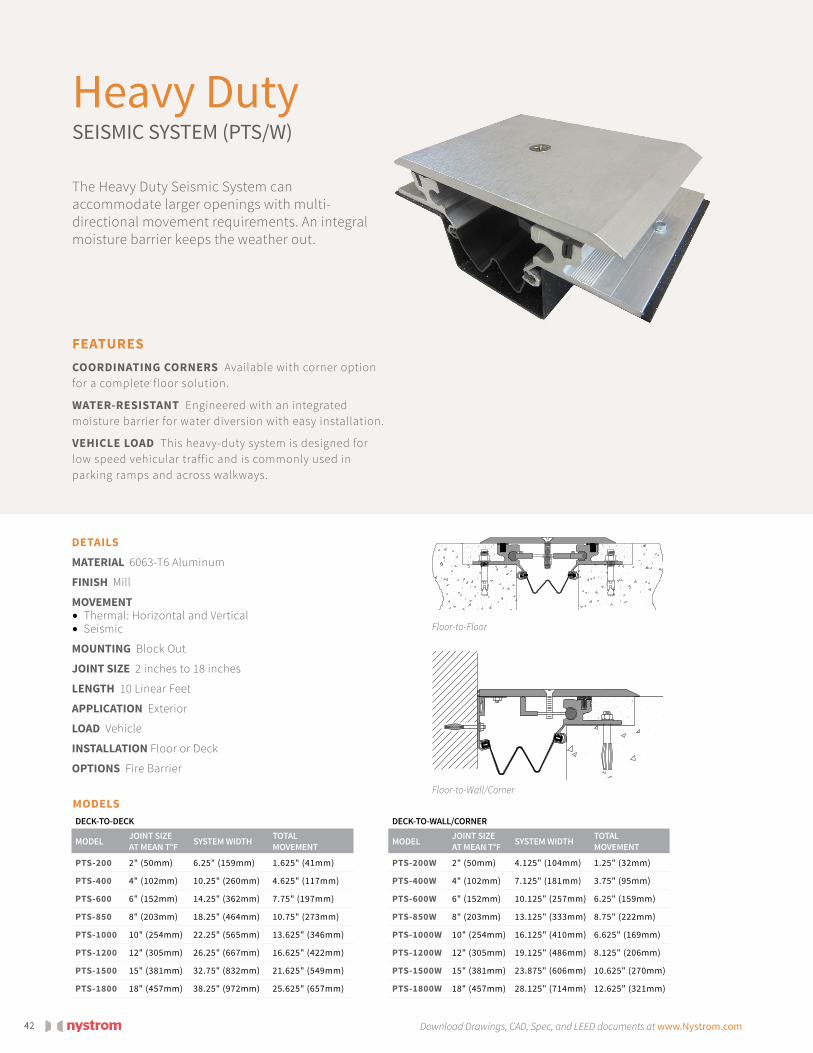
Heavy DutySEISMIC SYSTEM (PTS/W)
The Heavy Duty Seismic System can accommodate larger openings with multi-directional movement requirements. An integral moisture barrier keeps the weather out.
DETAILS
MATERIAL 6063-T6 Aluminum
FINISH Mill
MOVEMENT • Thermal: Horizontal and Vertical• Seismic
MOUNTING Block Out
JOINT SIZE 2 inches to 18 inches
LENGTH 10 Linear Feet
APPLICATION Exterior
LOAD Vehicle
INSTALLATION Floor or Deck
OPTIONS Fire Barrier
FEATURESCOORDINATING CORNERS Available with corner option for a complete floor solution.
WATER-RESISTANT Engineered with an integrated moisture barrier for water diversion with easy installation.
VEHICLE LOAD This heavy-duty system is designed for low speed vehicular traffic and is commonly used in parking ramps and across walkways.
MODELSDECK-TO-DECK
MODEL JOINT SIZE AT MEAN T°F SYSTEM WIDTH TOTAL
MOVEMENT
PTS-200 2" (50mm) 6.25" (159mm) 1.625" (41mm)
PTS-400 4" (102mm) 10.25" (260mm) 4.625" (117mm)
PTS-600 6" (152mm) 14.25" (362mm) 7.75" (197mm)
PTS-850 8" (203mm) 18.25" (464mm) 10.75" (273mm)
PTS-1000 10" (254mm) 22.25" (565mm) 13.625" (346mm)
PTS-1200 12" (305mm) 26.25" (667mm) 16.625" (422mm)
PTS-1500 15" (381mm) 32.75" (832mm) 21.625" (549mm)
PTS-1800 18" (457mm) 38.25" (972mm) 25.625" (657mm)
DECK-TO-WALL/CORNER
MODEL JOINT SIZE AT MEAN T°F SYSTEM WIDTH TOTAL
MOVEMENT
PTS-200W 2" (50mm) 4.125" (104mm) 1.25" (32mm)
PTS-400W 4" (102mm) 7.125" (181mm) 3.75" (95mm)
PTS-600W 6" (152mm) 10.125" (257mm) 6.25" (159mm)
PTS-850W 8" (203mm) 13.125" (333mm) 8.75" (222mm)
PTS-1000W 10" (254mm) 16.125" (410mm) 6.625" (169mm)
PTS-1200W 12" (305mm) 19.125" (486mm) 8.125" (206mm)
PTS-1500W 15" (381mm) 23.875" (606mm) 10.625" (270mm)
PTS-1800W 18" (457mm) 28.125" (714mm) 12.625" (321mm)
Floor-to-Floor
Floor-to-Wall/Corner

43Download Drawings, CAD, Spec, and LEED documents at www.Nystrom.com Expansion Joint Systems | FIRE BARRIER
Seismic FloorFIRE BARRIER SYSTEM (FLF/W)
Nystrom’s Seismic Fire Barrier System is recommended for openings up to 32 inches with seismic activity. The system is rated for 2 or 3 hour rating with factory made transitions for out of the box installation.
FEATURESFIRE-RATED Constructed of fire retardant materials to contain fires from spreading thru joint openings. Available in 2 or 3 hour ratings.
EASY INSTALLATION The system installs with tongue and groove process with limited or no caulking requirements.
FACTORY TRANSITIONS Available option for fire-rated factory transitions; refer to table.
DETAILS
MOVEMENT • Thermal: Horizontal and Vertical• Seismic
MOUNTING Recessed
JOINT SIZE 2 inches to 20 inches
LENGTH 10 Linear Feet
FIRE-RATING 2 hour or 3 hour
APPLICATION Interior
INSTALLATION Floor
COMPLIANCE UL 2079, ASTM E-1966, UL air leak, ASTM E 1399 cycling, hose stream
MODELSFLOOR-TO-FLOOR OR WALL-TO-WALL
MODEL JOINT SIZE AT MEAN T°F MODEL JOINT SIZE
AT MEAN T°F
FLF-200 2" (51mm) FLF-1000 10" (254mm)
FLF-300 3" (76mm) FLF-1200 12" (305mm)
FLF-400 4" (102mm) FLF-1400 14" (354mm)
FLF-500 5" (127mm) FLF-1600 16" (406mm)
FLF-600 6" (152mm) FLF-1800 18" (457mm)
FLF-800 8" (203mm) FLF-2000 20" (508mm)
CORNER
MODEL JOINT SIZE AT MEAN T°F MODEL JOINT SIZE
AT MEAN T°F
FLF-200W 2" (51mm) FLF-1000W 10" (254mm)
FLF-300W 3" (76mm) FLF-1200W 12" (305mm)
FLF-400W 4" (102mm) FLF-1400W 14" (354mm)
FLF-500W 5" (127mm) FLF-1600W 16" (406mm)
FLF-600W 6" (152mm) FLF-1800W 18" (457mm)
FLF-800W 8" (203mm) FLF-2000W 20" (508mm)
MODEL DESCRIPTION
-3WAY 3-Way T
-4WAY 4-Way T
FLH- Horizontal Directional Change
FLV90 90° Vertical Transition
FLH90 90° Horizontal Transition

Download Drawings, CAD, Spec, and LEED documents at www.Nystrom.com44
Seismic Wall FIRE BARRIER SYSTEM (FLW)
Nystrom’s Seismic Fire Barrier System is recommended for openings up to 32 inches with seismic activity. The system is rated for 2, 3 and 4 hour rating with factory made transitions when required for out of the box installation.
DETAILS
MOVEMENT • Thermal: Horizontal and Vertical• Seismic: Lateral Shear
MOUNTING Recessed
JOINT SIZE 2 inches to 20 inches
LENGTH 10 Linear Feet
FIRE-RATING 2 hour, 3 hour or 4 hour
APPLICATION Interior
INSTALLATION Wall or Ceiling
COMPLIANCE UL 2079, ASTM E-1966, UL air leak, ASTM E 1399 cycling, hose stream
FEATURESFIRE-RATED Constructed of fire retardant materials to contain fires from spreading thru joint openings. Available in 2, 3 or 4 hour ratings.
LARGE OPENINGS Available up to 32 inch opening for larger requirements.
EASY INSTALLATION The system installs with tongue and groove process with limited or no caulking requirements.
MODELS
MODEL JOINT SIZE AT MEAN T°F MODEL JOINT SIZE
AT MEAN T°F
FLW-200 2" (51mm) FLW-1000 10" (254mm)
FLW-300 3" (76mm) FLW-1200 12" (254mm)
FLW-400 4" (102mm) FLW-1400 14" (354mm)
FLW-500 5" (127mm) FLW-1600 16" (406mm)
FLW-600 6" (152mm) FLW-1800 18" (457mm)
FLW-800 8" (203mm) FLW-2000 20" (508mm)
Male End
Female End
45Download Drawings, CAD, Spec, and LEED documents at www.Nystrom.com Expansion Joint Systems | FIRE BARRIER
VTS
HTS
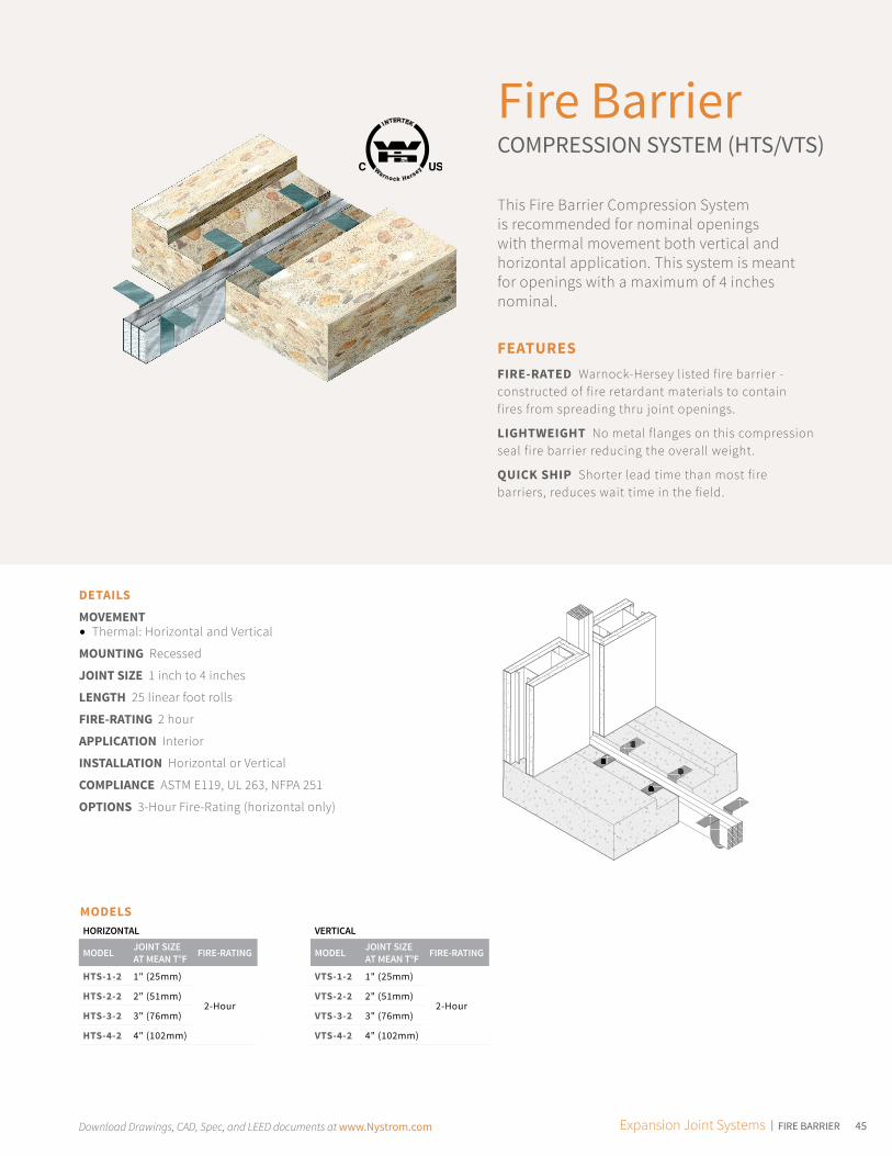
Fire BarrierCOMPRESSION SYSTEM (HTS/VTS)
This Fire Barrier Compression System is recommended for nominal openings with thermal movement both vertical and horizontal application. This system is meant for openings with a maximum of 4 inches nominal.
FEATURESFIRE-RATED Warnock-Hersey listed fire barrier - constructed of fire retardant materials to contain fires from spreading thru joint openings.
LIGHTWEIGHT No metal flanges on this compression seal fire barrier reducing the overall weight.
QUICK SHIP Shorter lead time than most fire barriers, reduces wait time in the field.
DETAILS
MOVEMENT • Thermal: Horizontal and Vertical
MOUNTING Recessed
JOINT SIZE 1 inch to 4 inches
LENGTH 25 linear foot rolls
FIRE-RATING 2 hour
APPLICATION Interior
INSTALLATION Horizontal or Vertical
COMPLIANCE ASTM E119, UL 263, NFPA 251
OPTIONS 3-Hour Fire-Rating (horizontal only)
MODELSHORIZONTAL
MODEL JOINT SIZE AT MEAN T°F FIRE-RATING
HTS-1-2 1" (25mm)
2-HourHTS-2-2 2" (51mm)
HTS-3-2 3" (76mm)
HTS-4-2 4" (102mm)
VERTICAL
MODEL JOINT SIZE AT MEAN T°F FIRE-RATING
VTS-1-2 1" (25mm)
2-HourVTS-2-2 2" (51mm)
VTS-3-2 3" (76mm)
VTS-4-2 4" (102mm)

Download Drawings, CAD, Spec, and LEED documents at www.Nystrom.com46
Aluminum Mill
Beige
AluminumClear Anodized
White
Stainless SteelBrush Finish
Gray
BrassBrush Finish
Black
Materials
Seal Colors
Moisture Barriers
Colors shown give only an indication of shade. Samples are available upon request.
Colors shown give only an indication of shade. Samples are available upon request.
DETAILS
MATERIAL 60A Durometer Neoprene
OPTIONS Drain Tube Assembly
MODELS
MODEL NOMINAL JOINT OPENING ROLL SIZE WIDTH
(INCH)THICKNESS (INCH)
219391"
100 Feet7"
.062"
21940 50 Feet
219412" to 3"
100 Feet12"
21942 50 Feet
219434" to 6"
100 Feet18"
21944 50 Feet
219457" to 10"
100 Feet24"
21946 50 Feet

47Download Drawings, CAD, Spec, and LEED documents at www.Nystrom.com Expansion Joint Systems | COMPRESSION SEALS
®
Visit www.Nystrom.com/Continuing-Education for more info.
Specialty Compression Seals also available.
Expansion JointCOMPRESSION SEALS
1 AIA HSW CE HourMANAGING BUILDING MOVEMENT WITH JOINTS
Nystrom has added a full-line of expansion joint compression seals including fire-rated, security (pick-resistant), chemical resistant, sound attenuation and more to our standard pre-compressed foam line. These new systems are:
Understanding building movement joints, forces, joint types, filler and cover options is an integral necessity.
Using this information will help assure that designs and specifications will achieve the desired success and prevent the deterioration that would otherwise occur in a building from movement.
AN EXPANDED OFFERING
COURSE CREDIT
SCAN THIS CODE
FOR MORE INFORMATION
COLOR COORDINATING
SOUND ATTENUATING
WAX FREE
EASY INSTALLATION
WATERTIGHT
NON-INVASIVE ANCHORING
THERMALLY INSULATING
UP TO 4X LABOR SAVINGS
Request your catalog at www.Nystrom.com.
Field applied corner beads (TYP)
Watertight factory applied silicone
Acrylic-impregnated precompressed foam
(wax free)
Intumescent coating
Joint size
MODELS
MODEL JOINT SIZES(INCHES)
TOTAL MOVEMENT INSTALLATION ADDED FEATURES CATALOG
PAGE
SES 0.5" to 12" 100% Wall/Ceiling 5
PES 0.5" to 8" 50% Wall/Ceiling Hurricane Tough 6
SER .5" to 1.25" 80% Wall/Floor 7
HES 0.5" to 8" 100% Floor 8
PDM 0.5" to 4" 55% Deck 9
FES2/3 0.5" to 6" 100% or 50% Wall/Ceiling Fire-RatedUL Labeled
10
FHES2/3 0.5" to 4" 100% or 50% Floor/Deck 11
PSES2 0.5" to 6" 100% Wall Fire-RatedUL LabeledPick Resistant
12
PHES2/3 0.5" to 4" 100% or 50% Floor/Deck 13

EXPANSION JOINT SYSTEMS CATALOG 08/17
9300 73rd Avenue NorthMinneapolis, MN 55428
Phone (800) 547-2635Fax (800) 317-8770
www.nystrom.com
Visit www.nystrom.com for the latest version of this document and more information.