Embed Size (px)
Citation preview

Reflex, Refix
Expansion vessels

We are only satisfied if you are
Reflex has set itself the goal of supporting you with wellthought-out solutions. Whatever job you need doing in watersupply engineering, why not put your trust in our comprehensiverange of products and accompanying tailored services? We will ensure that your decision to opt for Reflex is the right one in every respect – from advice and design to installation and ongoing operation.
Reflex’s mission is embodied in the company’s slogan:“Thinking solutions”. Reflex’s strength is to think in termsof solutions. Reflex develops ideas that help you to moveforward based on decades of experience, in-depth technicalunderstanding and intimate knowledge of the industry!
2

Diaphragm and bladder expansion vesselsFor heating, chilled water and solar applications
Overview expansion tank program 4-5
Working principle of expansion tank 6
Reflex N and NG 7
Reflex C 8
Reflex F 8
Reflex S 9
Reflex S/V 9
Reflex G 10
Accessories Reflex G 11
Reflex V 12
Selection table for heating expansion vessels 13-14
For potable water applications
Refix C-DE 15
Refix DC 15
Refix DE 16-17
Refix HW 18
Refix water shock arrestor 18
Refix DD 19
Refix DT 20-21
Accessories Refix DT 22
Selection table for potable water vessels 23
Refix DE/DT applications 24
In this product guide, we've summarised our entire product range for you meaning you can locate all our available products, series and technical information quickly and easily. All weights given are net weights. Reflex reserve the right to modify the details published in this document. General Sales Conditions of Reflex Winkelmann GmbH: Please consult www.reflex.de
We make sure that everything fits
Heating, cooling and hot water supply systems - the demands on supply equipment are varied and complex. You'll be well-advised for every eventuality with our coordinated product ranges. Reflex can offer you the right components for each specific task – and you can be sure that they can be integrated seamlessly into the interplay of a larger overall solution. The result: well thought-out systems that simply perform better.
Contents
The ReflexProduct Range
PressurisationSystems
ExpansionVesselsDeaeration
Systems &SeparationTechnology
Water Make-UpSystems & Water Treatment
Services
Hot WaterStorage Tanks & HeatExchangers
3

Expansion Vessels For Heating & Chilled Water
Heating, Chilled Water and Solar Applications
3 bar 6 bar 10 bar
FDiaphragm
CBladder
N & NGDiaphragm
SDiaphragm
GBladder
GBladder
V Intermediate Tank
F8-F24 litresDiaphragm
Page 10
C8-C80 litresNon-replaceable
bladderPage 10
NG8-NG140N200-N1000 litres
DiaphragmPage 9
G100-G10000 litresReplaceable bladder
Page 12-13
S2-S600 litresDiaphragm
Page 11
*S2 - S33with bladder
S/V 18-33 litresDiaphragm
Page 11
G100-G10000 litresReplaceable bladder
Page 12-13
*16 bar / 25 bar: Optional
V500-V5000 litres - 6 bar/120°CV6-V5000 litres - 10 bar/120°C
Page 14
4

Expansion Vessels For Heating & Chilled Water
Potable Water Applications
DD
CE
DT
Bla
dder
DE
HW
WSA
DC
Dia
phra
gm
DT60-DT3000/10 barDT80-DT3000/16 bar
Page 22
DD2-DD3/10 barDD8/25 bar
Page 21
C-DE8-C-DE8010 bar
Page 17
DE2-DE5000/10 barDE8-DE5000/16 barDE8-DE3000/25 bar
Page 18-19
Page 20HW25-HW100/10 bar
Page 200.165 litres/10 bar
Page 17DC25-DC600/10 bar
InternalCirculation
InternalCirculation
Vessels with WRAS- and/or ACS-certification upon request
ACS
5

Expansion Vessels For Heating & Chilled Water
System Pressure Range Pfin
PfinPini
P0
PstPsv
Pfin ≤ Psv - 0.5 bar (For Psv ≤ 5 bar)Pfin ≤ Psv x 0.9 (For Psv > 5 bar)
Pini = P0 + 0.3 barinitial pressure
P0 = Pst + 0.2 barPre-charge pressureMin. recommended=1 bar
Pressure fluctuation
PsvSafety valve
opening pressure
PstStaticHeight
P0Pre-chargepressure
PiniInitial pressure
PfinFinal system
pressure
PsvSafety valve
opening pressure
P0 Pini Pfin
VWR+VEX
VWR
Expansion vessels do have a number of important functions to fulfil: To restrict the pressure fluctuation of the system within certain limits (otherwise loss of water may occur via a responding safety relief valve) To prevent a negative pressure at the highest points of the installation in order to avoid the intrusion of air into the piping network To avoid steam building or the evaporation of the system liquid, e.g. in circuits with superheated water, solar systems To avoid cavitation inside pumps and fittings (preventing pump damage) To keep a water reserve in order to avoid a pressure drop caused by occasional losses of volume, e.g. due to venting after the initial starting up of the system To compensate for the variations of volume due to the changes in temperature of the system liquid
•
•
•
•
•
•
Vex = Vsys x EVWR = 0,005
Pfin - P0
Pfin + 1Facc =
Vex + VWR
Facc Vn ≥
Pfin = Psv - 0,5 bar (Psv < 5 bar)Pfin = Psv - 0,1 x Psv bar (Psv > 5 bar)
VN = Nominal volume, litres
Vex = Expanded volume, litres
VWR = Water reserve, litres
Vsys = Total water content, litres
e = Expansion coefficient (Eg.: for 90°C, e = 0,0355)
6
Expansion Vessels For Heating & Chilled Water
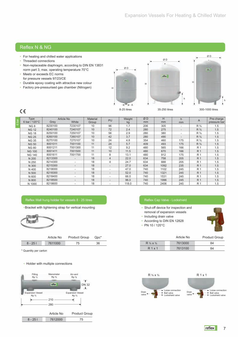
For heating and chilled water applicationsThreaded connectionsNon-replaceable diaphragm, according to DIN EN 13831norm part 3, max. operating temperature 70°CMeets or exceeds EC normsfor pressure vessels 97/23/CEDurable epoxy coating with attractive new colourFactory pre-pressurised gas chamber (Nitrogen)
NG 8NG 12NG 18NG 25NG 35NG 50NG 80NG 100NG 140N 200N 250N 300N 400N 500N 600N 800N 1000
82301008240100825010082601008270100800101180012118001411800161182133008214300821530082180008218300821840082185008218600
723010772401077250107726010772701077001100700130070015007001700
--------
1010101010111111111818181818181818
9672564224241210844------
1.72.42.93.74.85.79.211.513.122.024.727.047.052.066.096.0118.0
206280280280354409480480480634634634740740740740740
305275380490460493565670912758888
109211021321153119962406
----
175175166166175205205235245245245245245
R ¾R ¾R ¾R ¾R ¾R ¾R 1R 1R 1R 1R 1R 1R 1R 1R 1R 1R 1
1.51.51.51.51.51.51.51.51.51.51.51.51.51.51.51.51.5
6 ba
r
Ø D
Ø DØ D
H
HH
8-25 litres 35-250 litres 300-1000 litres
Reflex Wall hung holder for vessels 8 - 25 litres Reflex Cap Valve - Lockshield
Shut-off device for inspection and removal of expansion vessels Including drain valveAccording to DIN EN 12828PN 10 / 120°C
Bracket with tightening strap for vertical mounting
Article No Product Group Qpc*
8 - 25 l 757611000 36
* Quantity per carton
Holder with multiple connections
Article No Product Group
847613000R ¾ x ¾7613100R 1 x 1 84
Article No Product Group
FillingRp ½
ManometerRp ⅜
Air-ventRp ⅜
Expansion VesselRp ¾
Expansion VesselRp ¾
DN 32
R ¾ x ¾ R 1 x 1
Drainvalve
Loose connectionBall valveLockshield valve
Drainvalve
Loose connectionBall valveLockshield valve
8 - 25 l 7612000 75
210
280
Reflex N & NG
Article NoGrey White
MaterialGroup PU Weight
kgØ Dmm
Hmm
hmm A Pre-charge
pressure barType
6 bar / 120°C
A
hh
7

For heating and chilled water applicationsSuitable for anti-frost mixture up to 50%Provided with suspension bracket for easy installationNon-replaceable bladder according to DIN EN 13831 norm part 3, max. operating temperature 70°CMeets or exceeds EC norms for pressure vessels 97/23/ECDurable epoxy coating with attractive new colourFactory pre-pressurised gas chamber (Nitrogen)Reflex EN, now with it’s new name Reflex C
Reflex C
Reflex F
PU
PU
Weightkg
Weightkg
Ø Dmm
Hmm
Hmm
dmm
Dmm
Wmm
Wmm
A
A
Pre-chargepressure bar
Pre-chargepressure bar
Article No
Article No
GreyMaterialGroup
MaterialGroup
Type3 bar / 120°C
G ½G ½G ¾G ¾G ¾G ¾G ¾
C 8C 12C 18C 25C 35C 50C 80
8280000828010082802008280300828040082805008280600
17171717171717
280354354409480480634
5264769397
125135
9660424224208
287362362419457457612
2.83.24.75.57.38.1
14.5
163168222239240318325
1.01.01.01.01.01.51.5
3 ba
r
Ø D
H
A
d
W
Flat vessel for heating (built-in boiler applications)According to DIN EN 13831 norm part 3,max. operating temperature 70°CFrom 18 litres with wall-hung clipMeets or exceeds EC normsfor pressure vessels 97/23/CEDurable epoxy coatingFactory pre-pressurised gas chamber (Nitrogen)
Ø D Ø DWW W
H
A A
8 litres 12-24 litres
Expansion Vessels For Heating & Chilled Water
Type3 bar / 120°C
F 8F 12F 15F 18F 24
1515151515
6.37.78.28.79.4
389350350350350
96000119600030960004096000009600010
5436362825
389444444444444
88108134158180
G 3/8G 1/2G 3/4G 3/4G 3/4
0.751.01.01.01.0
3 ba
r
8
Expansion Vessels For Heating & Chilled Water
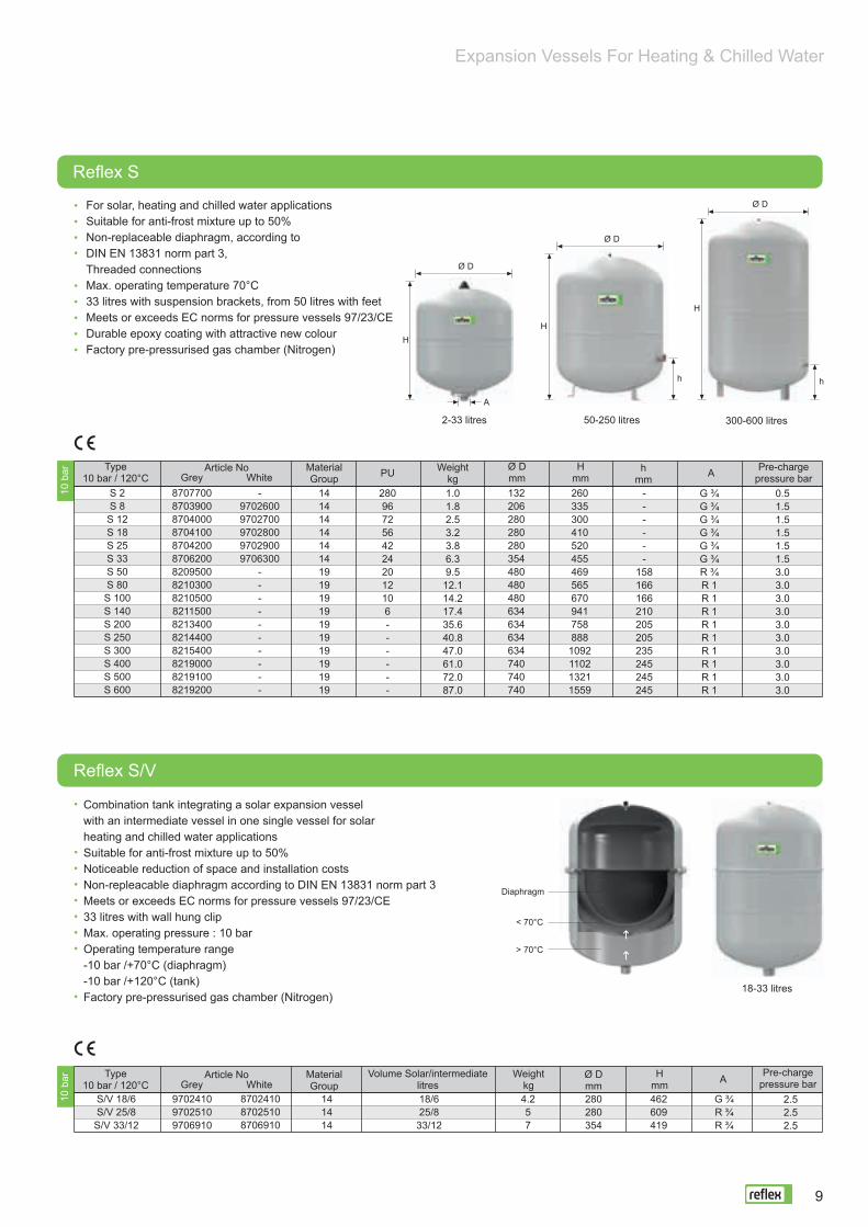
For solar, heating and chilled water applicationsSuitable for anti-frost mixture up to 50%Non-replaceable diaphragm, according toDIN EN 13831 norm part 3, Threaded connectionsMax. operating temperature 70°C33 litres with suspension brackets, from 50 litres with feetMeets or exceeds EC norms for pressure vessels 97/23/CEDurable epoxy coating with attractive new colourFactory pre-pressurised gas chamber (Nitrogen)
Reflex S
Article No
Article No
Grey
Grey
White
White
MaterialGroup
MaterialGroup
PU Weightkg
Ø Dmm
Hmm
hmm A Pre-charge
pressure barType
10 bar / 120°C
Type10 bar / 120°C
S 2S 8S 12S 18S 25S 33S 50S 80S 100S 140S 200S 250S 300S 400S 500S 600
8707700870390087040008704100870420087062008209500821030082105008211500821340082144008215400821900082191008219200
-97026009702700970280097029009706300
----------
132206280280280354480480480634634634634740740740
14141414141419191919191919191919
260335300410520455469565670941758888
1092110213211559
28096725642242012106------
------
158166166210205205235245245245
1.01.82.53.23.86.39.5
12.114.217.435.640.847.061.072.087.0
G ¾G ¾G ¾G ¾G ¾G ¾R ¾R 1R 1R 1R 1R 1R 1R 1R 1R 1
0.51.51.51.51.51.53.03.03.03.03.03.03.03.03.03.0
Combination tank integrating a solar expansion vesselwith an intermediate vessel in one single vessel for solarheating and chilled water applicationsSuitable for anti-frost mixture up to 50%Noticeable reduction of space and installation costsNon-repleacable diaphragm according to DIN EN 13831 norm part 3Meets or exceeds EC norms for pressure vessels 97/23/CE33 litres with wall hung clipMax. operating pressure : 10 barOperating temperature range-10 bar /+70°C (diaphragm)-10 bar /+120°C (tank)Factory pre-pressurised gas chamber (Nitrogen)
10 b
ar10
bar A Pre-charge
pressure barØ Dmm
Hmm
Weightkg
Volume Solar/intermediatelitres
2-33 litres 50-250 litres 300-600 litres
Ø D
Ø D
Ø D
H
HH
hh
A
S/V 18/6S/V 25/8S/V 33/12
970241097025109706910
141414
4.257
870241087025108706910
18/625/8
33/12
280280354
462609419
G ¾R ¾R ¾
2.52.52.5
Diaphragm
< 70°C
> 70°C
18-33 litres
Reflex S/V
9

For heating and chilled water applicationsReplaceable bladder, according according to DIN EN 13831 norm part 3, max. operating temperature 70°CMeets or exceeds EC norms for pressure vessels 97/23/ECInspection opening (Above 1000 litres Ø 1000 mm)Factory-mounted pressure gaugeThreaded connections up to 1000 litresFlanged connections above 1000 litres3000 to 10000 litres with upper flange Durable epoxy coating with attractive new colourFactory pre-pressurised gas chamber (Nitrogen)
Expansion Vessels For Heating & Chilled Water
Reflex G
Options
Operation pressure >10 barFlanged connection: For G 1000 - 5000 tanks: DN 150, DN 200 For G 8000 - 10000 tanks: DN 300
Weightkg
Weightkg
Ø Dmm
Ø Dmm
Hmm
Hmm
hmm
hmm
A
A
Pre-chargepressure bar
Pre-chargepressure bar
MaterialGroup
MaterialGroup
Type6 bar / 120°C
Type10 bar / 120°C
Article No
Article No
Grey
Grey
6 ba
r10
bar
Per Request
G 100G 200G 300G 400G 500G 600G 800
G 1000 Ø 740G 1000 Ø 1000
G 1500G 2000G 3000G 4000G 5000G 8000G 10000
85190008519100851920085216058521705852260585236108546605852460585266058527605854460585296058530605
21212121212121212222222222222222
480634634740740740740740
10001200120015001500150015001500
153190190146146146146146307305305334334344236236
19.237.042.043.051.066.094.0
150.0228.0280.0250.0620.0770.0849.0979.01166.0
870972
12721253147317182183259319731971243124803053358854046560
G 1G 1 ¼G 1 ¼G 1G 1G 1G 1G 1
DN 65/PN 6DN 65/PN 6DN 65/PN 6DN 65/PN 6DN 65/PN 6DN 65/PN 6
DN 100/PN16DN 100/PN16
3.53.53.53.53.53.53.53.53.53.53.53.53.53.53.53.5
G 100G 200G 300G 400G 500G 600G 800
G 1000 Ø 740G 1000 Ø 1000
G 1500G 2000G 3000G 4000G 5000G 8000G 10000
8518000851810085182008521005852100685220068523005854600585240058526005852700585440058529005853000585450008533000
21212121212121212222222222222222
480634634740740740740740
10001200120015001500150015001500
153144144133133263263263286291291320320320236236
19.233.434.651.057.1118.0166.0174.0335.0390.0485.0830.0
1064.01274.01470.01750.0
870972
12731245147518592324260420011991245125323107364254046560
G 1G 1 ¼G 1 ¼G 1 ¼G 1 ¼G 1 ½G 1 ½G 1 ½
DN 65/PN 16DN 65/PN 16DN 65/PN 16DN 65/PN 16DN 65/PN 16DN 65/PN 16
DN 100/PN 16DN 100/PN 16
3.53.53.53.53.53.53.53.53.53.53.53.53.53.53.53.5
Ø D
Ø D
Ø D
H
A
H
H
100-500 litres 600-1000 litresØ 740
1000-10000 litresØ 1000
h
10

Expansion Vessels For Heating & Chilled Water
AccessoriesMBM ll Bladder Rupture Detector
German TÜV Certification
AG Connection Set
Reflex Cap Valve - Lockshield
Digital Pressure Gauge
For the signalling of bladder rupture in Reflex G Consists of an electrode and relay(factory-mounted) Operates 230 V / 50 Hz supplyThree terminal dry contactRecommended: 1 device for each vessel
Article No : 7857700 Material Group : 86
German TÜV factory test certification
Article no : 7945610 Material Group : 95
For quick installation and easy inspection of vessel Including lockshield valve G 1/2 drain valve with loose connection According to DIN EN 12828PN 16 / 120°C
Shut-off device for inspection and removal of expansion vesselSuitable for G, S, N, NG and V vessels
R 3/4x3/4 Article No : 7613000 Material Group : 84R 1x1 Article No : 7613100 Material Group : 84
Display range up to approximately 9 barPressure indication in bar, kPa, psi
Article No : 9119198 Material Group : 86
Material Group Suitable For ModelArticle NoArticleR 1
R 1 ¼R 1 ½
808080
911920491192059119206
G 400 - G 1000 Ø 740/10 barG 100 - G 500/10 bar
G 600 - G 1000 Ø 740/10 bar
RelayWall mounted (on site)
ElectrodeFactory mounted
BladderControl
Vessel Coupling Connection
Drain Valve
Lockshield Valve
Expansion line
11

Expansion Vessels For Heating & Chilled Water
Necessary for installations subject to norm EN 13831with return temperatures > 70°C or cooling systems at ≤ 0°CTo avoid faster aging of diaphragm/bladder when subjected to higher temperatures(heating) and to prevent condensation water from freezing (cooling)Meets or exceeds EC norms for pressure vessels 97/23/ECFlanged water connections: 200 litres and aboveDurable epoxy coating with attractive new colour
Weightkg
Ø Dmm
Hmm
hmmPU AMaterial
GroupType
6 bar / 120°CArticle No
Grey
Weightkg
Ø Dmm
Hmm
hmmPU AMaterial
GroupType
10 bar / 120°CArticle No
Grey
Ø D
Ø DØ D
Ø D
Ø D
Ø D
H H HH
H
H
hA
A
6-20 litres 40-60 litres 200-350 litres 500-750 litres 1000-2000 litres 3000-5000 litres
Options V Intermediate Tank
Reflex V Intermediate Tank
Operation pressure >10 barNominal volume > 5000 litres Operation temperature > 120°CGerman TÜV factory test certificationIndividual approval carried out by the TÜV [Notified body] in accordance with the Pressure Equipment Directive 97/23/EC
V 500V 750V 1000V 1500V 2000V 3000V 4000V 5000
88528008851800885190588523058852405885250588534058854805
2424242424242424
--------
160.0205.0310.0445.0545.0775.0
1060.01095.0
750750
100012001200150015001500
16322323202020202478255631313666
210210305305305340340340
DN 40/PN 6DN 40/PN 6DN 65/PN 6DN 65/PN 6DN 65/PN 6DN 65/PN 6DN 65/PN 6DN 65/PN 6
V 6V 12V 20V 40V 60V 200V300V 350V 1000V 1500V 2000V 3000V 4000V 5000
84031008403200840200084034008402600870180087019008702400840020584003058400405840050584006058400705
2424242424242424242424242424
9672421812---------
2.03.04.07.8
23.043.048.051.0
560.0780.0940.0
1405.01930.02015.0
206280280409409634634640
100012001200150015001500
244287360562732901
12011341205520452055259831783173
---
113172142142210286284284313313313
R 3/4R 3/4R 3/4R 1R 1
DN 40/PN 16DN 40/PN 16DN 40/PN 16DN 65/PN 16DN 65/PN 16DN 65/PN 16DN 65/PN 16DN 65/PN 16DN 65/PN 16
6 ba
r10
bar
12

Expansion Vessels For Heating & Chilled Water
V Intermediate Tank Applications
V Intermediate tank protect the diaphragms of expansion vessels from impermissible temperature loads. According to DIN 4807 T3 and EN 13831, the continuous temperature on the diaphragms must not exceed 70°C. In a cooling water systems, temperatures ≤ 0°C should be avoided.
In heating & solar systemsAs a rule, heating & solar systems are operated at returntemperatures of ≤ 70°C. The installation of intermediatetank is not necessary. In the case of older systems andindustrial plants, return temperatures > 70°C are sometimesunavoidable.
In cooling circuits If temperature is 0°C, we recommend to an intermediate tankwill be installed before the cooling vessel. To size the intermediatetank volume (Vn) , consult Reflex calculation program.
1) Reflex N, expansion vessel for boiler circuit 2) Storatherm Aqua Solar hot water heater 3) Refix DD, Hygienic expansion vessel 4) Exvoid, Air separator for solar circuit 5) Reflex S, Expansion vessel for solar system6) Reflex V, Intermediate tank
4
6
2
3
5
1 Reflex IntermediateTank
Reflex S
t ≤ 70°C
t > 70°C t ≤ 0°C
t > 0°C
Vn Vn
In a solar system application the expansion vessel installed to the flow pipe line therefore, The pump pressure needs to be considered while setting the precharge gas P0.
For the life time of the membrane we recommend to install a Reflex V intermediate tank before the expansion vessel if the return flow is > 70°C.
Applications
13

Expansion Vessels For Heating & Chilled Water
Quick Selection Table For Diaphragm Expansion Vessels
Heating systems: 90/70°C
Approximate water content:RadiatorsVA = Q [kW] x 13.5 I/kWPanel-type radiatorsVA = Q [kW] x 8.5 I/kW
Visit www.reflex.de/pro for further information and the option of downloading free of charge.
Selection examplePSV = 3 barH = 13 mQ = 40 kW (plates 90/70°C)
VPH = 1000 I (V buffer storage tank)
CalculateVA = 40 kW x 8.5 I/kW + 1000 = 1340 I
P0 ≥ 0.2 bar = 1.5 bar13( (
H [m]10
10
From tha table:With PSV = 3 bar, P0 = 1.5 barVA = 1340 litresVn = 250 litres (for VA max. 1360)
Selected:1 x Reflex N 250.6 bar1 x cap ballvalve
Reflex recommendations:
Select sufficiently high safety valve actuation pressure: Psv ≥ P0 + 1.5 barIf possible, apply a 0.2 bar margin when calculating the gasinput pressure: P0 ≥ + 0.2 barDue to the required supply pressure for the circulating pumps, select an pre-setpressure of at least 1 bar for roof-mounted systems also: P0 ≥ 1 barIn a vented system in cold conditions, set the water-side filling or initial pressureat least 0.3 bar higher than the pre-set pressure: Pfil ≥ P0 + 0.3 bar
Safety vayve Psv bar
Content litres VA
Pre-set pressure bar P0
For detailed calculations, refer to our brochure “Pressurisation Systems - Planning, Calculation, Equipment” or visit www.reflex.de to use our Reflex Pro calculation software
1.0
30
45
85
150
240
380
500
620
870
1240
1550
1860
2480
3100
3720
4970
6210
1,5
55
80
140
230
330
540
870
1090
1530
2180
2720
3270
4360
5450
6540
8710
10890
1.0
50
75
130
220
340
510
840
1050
1470
2100
2630
3150
4200
5250
6300
8400
10500
litres
8
12
18
25
33
50
80
100
140
200
250
300
400
500
600
800
1000
1,5
-
-
-
33
80
110
170
210
300
420
530
630
850
1060
1270
1690
2120
2.0
30
45
85
150
240
380
650
820
1140
1630
2040
2450
3270
4080
4900
6540
8170
1,5
19
29
60
120
200
320
440
540
760
1090
1360
1630
2180
2720
3260
4350
5440
2.0
55
85
140
230
360
550
890
1110
1560
2230
2790
3340
4460
5570
6680
8910
11140
3,5
-
-
8
43
95
170
320
420
510
720
900
1080
1440
1800
2170
2890
3610
litres
8
12
18
25
35
50
80
100
140
200
250
300
400
500
600
800
1000
2,5
5
7
28
70
130
230
410
430
610
870
1090
1300
1740
2170
2610
3480
4350
1,8
-
-
17
55
110
200
260
330
460
660
820
990
1320
1650
1980
2640
3300
2,5
37
55
100
170
270
420
710
890
1250
1780
2230
2670
3570
4460
5350
7130
8910
4.0
-
-
-
-
5
43
95
120
170
240
300
360
480
600
730
970
1210
0.5
85
120
200
320
470
700
1120
1400
1960
2800
3500
4200
5600
6920
8400
11200
13830
3.0
-
-
-
-
25
70
120
150
200
290
370
440
580
730
880
1170
1460
litres
8
12
18
25
33
50
80
100
140
200
250
300
400
500
600
800
1000
3.0
16
24
55
110
180
300
530
670
940
1340
1670
2010
2670
3340
4010
5350
6680
litres
8
12
18
25
33
50
80
100
140
200
250
300
400
500
600
800
1000
2.5 Vn 3.0 Vn VnVn 4.0 5.0
14

Expansion Vessels For Heating & Chilled Water
For systems not subject to DIN 1988 requirements, e.g. fire-extinguishing and service water systems, geothermal energy For heating, heat - pump, chilled water and solar applications Non-replaceable bladder according to DIN EN 13831 norm part 3Threaded stainless steel connectionMeets or exceeds EC norms for pressure vessels 97/23/ECDurable epoxy coatingFactory pre-pressurised gas chamber (Nitrogen)Provided with suspension bracket for easy wall mounting
For systems not subject to DIN 1988 requirements, e.g. fire-extinguishing and service water systems, geothermal energy For potable water, fire fighting and hydro-pneumatic well applicationsNon-replaceable diaphragm, according to DIN EN 13831 norm part 3All vessel parts in contact with water are coated against corrosionMeets or exceeds EC norms for pressure vessels 97/23/ECDurable epoxy coatingFactory pre-pressurised gas chamber (Nitrogen)Vessels with WRAS- and/or ACS-certification upon requestReflex DE Junior, now with it’s new name Reflex DC
Weightkg
Weightkg
Ø Dmm
Ø Dmm
Hmm
Hmm
Wmm
dmm
hmm
PU AMaterialGroup
MaterialGroup
Type10 bar / 70°C
Type10 bar / 70°C
Article No
Article No
Blue
Blue
Pre-chargepressure bar
Pre-chargepressure bar
A
Refix C - DE
Refix DC
C-DE 8C-DE 12C-DE 18C-DE 25C-DE 35C-DE 50C-DE 80
7270900727091072709207270930727094072709507270960
17171717171717
3.85.25.68.2
13.015.422.4
300375375430500500654
5264769397
125135
9660424224208
280354354409480480634
163168222239240318325
G ½G ½G ¾G ¾G ¾G ¾G ¾
4.04.04.04.04.04.04.0
DC 25DC 50DC 80DC 100DC 140DC 200DC 300DC 400DC 500DC 600
54545454545454545454
280409480480480634634740740740
-1131041041049193818273
7200400730960073097007309800730990073635007363600736370073638007363900
4.812.517.521.129.040.052.078.080.0
103.0
5105886807859978831184117313921629
G 1R 1R 1R 1R 1R 1R 1R 1R 1R 1
2.04.04.04.04.04.04.04.04.04.0
Ø D
H
W
d
A
8-80 litres
OptionR ¾ x ¾
Article No: 7613000
Ø D
OptionR 1 - AG ConnectionArticle No: 9119204
Ø D
Ø D
H
H
h
H
A
25 litres 50-400 litres 500-600 litres
10 b
ar/7
0°C
10 b
ar/7
0°C
ACS
15

Expansion Vessels For Heating & Chilled Water
For systems not subject to DIN 1988 requirements, e.g. fire-extinguishing and service water systems, geothermal energyFor potable water, water heating andhydro-pneumatic well applicationsBladder according to DIN EN 13831 norm part 3 From 50 litres volume with replaceable bladderAll vessel parts in contact with water arecoated against corrosionMeets or exceeds EC norms for pressure vessels 97/23/ECFitted with manometer from Ø 1000 mmThreaded connections up to 1000 litresFlanged connections above 1000 litres3000 to 10000 litres with upper flangeDurable epoxy coatingFactory pre-pressurised gas chamber (Nitrogen)Vessels with WRAS- and/or ACS-certification upon request
For the signalling of bladder rupture in Reflex DE 60 litres and above Consists of an electrode and relay(factory-mounted) Operates 230 V / 50 Hz supplyThree terminal dry contactRecommended: 1 device for each vessel
Article No : 7857700 Material Group : 86
with legs1)
RelayWall mounted (on site)
ElectrodeFactory mounted
BladderControl
Ø D
Ø D
Ø D
HH
H
hA A
2-25 litres 33 litres 50-500 litres
OptionWall-hung bracket
Article No: 7611000
Weightkg
Ø Dmm
Hmm
hmmPU AMaterial
GroupType
10 bar / 70°CArticle No
BlueDE 2DE 8DE 12DE 18DE 25DE 33
DE 33 1)DE 50DE 60DE 80DE 100DE 200DE 300DE 400 DE 500 DE 600DE 800
DE 1000 Ø 740DE 1000 Ø 1000
DE 1500DE 2000DE 3000DE 4000DE 5000DE 8000DE 10000
4040404040404042424242424242424242424444444444444444
1.01.82.43.23.85.76.59.511.214.016.036.541.573.0
103.0128.0176.0214.0427.0542.0717.0962.0
1085.01050.01750.01750.0
260335307410520454520604734745850967
12671245147518592325260420011991245125213070363554046560
288967256422424201810104--------------
132206280280280354354409409480480634634740740740740740
10001200120015001500150015001500
mm------
66102153153153150150139133263263286291291320320320236236
G ¾G ¾G ¾G ¾G ¾G ¾G ¾G 1G 1G 1G 1
G 1 ¼G 1 ¼G 1 ¼G 1 ¼G 1 ½G 1 ½G 1 ½
DN 65/PN 16DN 65/PN 16DN 65/PN 16DN 65/PN 16DN 65/PN 16DN 65/PN 16
DN 100/PN 16DN 100/PN 16
720030073010007302000730300073040007303900730550073060057306400730650073066007306700730680073068507306900730695073069607306970731140573116057311705731180573540007354200
Upon Request
10 b
ar
Refix DE
MBM ll Bladder Rupture Detector
ACS
16

Expansion Vessels For Heating & Chilled Water
Weightkg
Ø Dmm
Hmm
hmmPU AMaterial
GroupType
16 bar / 70°CArticle No
Blue
Upon Request
DE 8DE 12DE 25DE 80DE 100DE 200DE 300DE 400 DE 500 DE 600DE 800
DE 1000 Ø 740DE 1000 Ø 1000
DE 1500DE 2000DE 3000DE 4000DE 5000DE 8000DE 10000
730100673021057304015734860073486107348620734863073486407348650734866073486707348680731280573129057313005731310573541007354300
4040404242424242424242424444444444444444
206280280480480634634740740740740740
10001200120015001500150015001500
967224-----------------
335309520745850967
12671394161418592324260420011991245125213110364554046560
2.83.55.8
18.021.057.066.0116.0127.0158.0202.0244.0530.0685.0895.0
1240.01100.01120.01750.01750.0
---
153153150150265265265265265286291291320320320236236
G ¾G ¾G ¾G 1G 1
G 1 ¼G 1 ¼4G 1 ½G 1 ½G 1 ½G1 ½G1 ½
DN 65/PN 16DN 65/PN 16DN 65/PN 16DN 65/PN 16DN 65/PN 16DN 65/PN 16DN 100/PN 16DN 100/PN 16
Weightkg
Ø Dmm
Hmm
hmmPU AMaterial
GroupType
25 bar / 70°CArticle No
Blue
16 b
ar25
bar
DE 8DE 80DE 120DE 180DE 300DE 400DE 600DE 800
DE 1000 Ø 750DE 1000 Ø 1000
DE 1500DE 2000DE 3000
7290100731760073137007313500731380073133007321500732120073210007322200732210073134007345700
40444444444444444444444444
206450450450750750750750750
1000120012001500
60------------
334942
12531528131814231868226827682051207125312609
2.470.0
100.0116.0150.0245.0290.0355.0245.0800.0850.0960.0
1550.0
-159159159160160159159159242291240269
G ¾DN 50/PN 40DN 50/PN 40DN 50/PN 40DN 50/PN 40DN 50/PN 40DN 50/PN 40DN 50/PN 40DN 50/PN 40DN 65/PN 40DN 65/PN 40DN 65/PN 40DN 65/PN 40
Refix DE
Options
Operation pressure of 40 barFlanged connection DN 150 etc.Inner lining according to DIN/DVGW norms Stainless steel connection
Ø D
Ø DØ D
Ø D
H H H
H
hA
600-1000 litresØ 740
80 - 1000 litresØ 740/25 bar
1000-2000 litresØ 1000
3000-10000 litres
17

Refix HW
Water Shock Arrestor
For systems not subject to DIN 1988 requirements, e.g. fire-extinguishing and service water systems, geothermal energyFor potable water, fire fighting and hydro-pneumatic well applicationsBladder, replaceable from 50 litres according to DIN EN 13831norm part 3, max. operating temperature 70°CAll vessel parts in contact with water are coatedagainst corrosionMeets or exceeds EC norms for pressure vessels 97/23/ECDurable epoxy coatingFactory pre-pressurised gas chamber (Nitrogen)From 50 litres volume with replaceable bladderVessels with WRAS- and/or ACS-certification upon request
To be used along devices where sudden pressure build-up is causedby quick shut-off such as washing machines, dish washers etc.Meets or exceeds EC norms for pressure vessels 97/23/ECVolume 165 cm3Durable epoxy coatingFactory pre - pressurised gas chamber 4 bar (Nitrogen)10 bar / 70°CVessels with WRAS- and/or ACS-certification upon request
Article No : 7351000 Material Group : 74
Pressure Vessels For Potable Water Applications
Ø D
H
L
L2
W
A
W2
Ø 86
115 mm
G ½
Weightkg
Ø DmmPUMaterial
GroupType
10 bar / 70°CArticle No
BlueH
mmL
mmL2mm
W2mm
Wmm A
HW 25HW 50HW 60HW 80HW 100
72003107200320720033072003407200350
4949494949
294 433 433 495 495
5.515.016.017.419.4
228175175230340
270350350355355
3620-
16 16
520 503 573 595 705
280409480480480
214285285285285
G ¾G 1G 1G 1G 1
10 b
ar
ACS
ACS
18

Pressure Vessels For Potable Water Applications
RefixRefix DD/DT Hygienic Pressure Vessels
The Refix DD/DT vessels continue to deliver unparalleled performance andpersistence, meeting all the tough requirements of the German DIN 4807part 5. The shell of the tank is made of heavy gauge steel and has epoxycoating from inside. The dual water connection for internal circulation delivered in various sizesranging from 1 1/4 up to DN 100. The butyl rubber bladder offers the lowestpermeability compared to any material used today.
For potable water applications according toGerman DIN/DVGW 4807 norm part 5Integrated internal circulationNon-replaceable bladder according to German KTW-C normMeets or exceeds EC norms for pressure vessels 97/23/ECInner anti-corrosion coating according toGerman KTW-A (food stuff regulation)Factory pre-pressurised gas chamber 4 bar (Nitrogen)Can be installed with Flowjet - flow through valveConnectable to T-piece Rp 3/4 (included in Refix DD delivery)Vessels with WRAS- and/or ACS-certification upon request
For easy assembly and maintenance ofRefix DD pressure tanks according toDIN/DVGW 4807 norm part 5Max. operating pressure 16 barMax. operating temperature 70°C
Article No : 9116799 Material Group : 85
Refix DD
Flowjet - Flow Through, Shut-off and Discharge Valve
T - Piece is not included to the delivery1)
Weightkg
Weightkg
Dmm
Dmm
MaterialGroup
MaterialGroup
PU
PU
Type10 bar / 70°C
Type10 bar / 70°C
Article No
Article No
Green
Green
White
White
Hmm
Hmm
A
A
DD 2DD 8DD 12DD 18DD 25DD 33
738150073080007308200730830073084007380700
-73077007307800730790073804007380800
484848484848
1.01.92.02.83.65.8
269345318420530468
2889672564224
132206280280280354
G 3/4G 3/4G 3/4G 3/4G 3/4G 3/4
1)
DD 8 7290200 7290300 48 3.4 34560 206 G ¾
Ø D
A A
HH
Ø D
8-25 litres 33 litres
Rp ¾ - T - Piece(DD 8 - DD 33)
Rp ¾ - T - Piece(DD 8 - DD 33)
InternalCirculation
Flowjet
Flowjet
10 b
ar25
bar
ACS
19

Pressure Vessels For Potable Water Applications
For potable water applications according to German DIN/DVGW 4807 norm part 5Integrated internal circulation In case of Rp 1/4 connection (60 - 500 litres) factory-equipped withFlowjet: flow-through, shut-off and discharge valveReplaceable bladder according to German KTW-C normInner anti-corrosion coating according to German KTW-A (food stuff regulation)Meets or exceeds EC norms for pressure vessels 97/23/ECFactory pre-pressurised gas chamber 4 bar (Nitrogen)Vessels with WRAS- and/or ACS-certification upon requestReflex DT5, now with it’s new name Reflex DT
Refix DT
60-500 litresFlowjet
600-1000 litres (Ø 740)Duo Connection
Ø D
Ø D
H
H
A
hh
DT 60DT 80
DT 100
DT 200
DT 300
DT 400
DT 500
DT600
DT 800
DT 1000 Ø 740
DT 1000 Ø 1000
DT 1500
DT 2000
DT 3000
7309000730910073650007335705733580573092007365400736540573654067309300736510073651057365106730940073652007336305733640573193057365500733650573366057309500736530073653077365305736560073367057336806736570073369057337006736580073371057337205732010573373057337405732030573375057337605732050573377057337805732070573379057338005
47474747474747474747474747474747474747474747474747474747474747474747464646464646464646464646
409480480480480480480480480634634634634634634634634740740740740740740740740740740740740740740740740740
100010001000120012001200120012001200150015001500
15.017.023.024.726.819.226.827.828.937.053.054.057.043.559.060.063.073.079.080.083.069.085.086.089.0
164.0165.0177.4204.0205.0208.0244.0245.0248.0386.2386.2386.2502.4502.4502.4686.5686.5686.5
1054.01057.01057.0
806510011011565100110115801051151208010511512070951051107090100110235235235235235235235235235160150140160150140160150140190180170
766765765765765870870870870975975975975
127512751275127512451245124512451475147514751475186018601860232523252325260426042604200020002000200020002000245024502450252025202520
Weightkg
Ø Dmm
MaterialGroup
Type10 bar / 70°C
Article NoConnectionGreen
Hmm
hmm
10 b
ar
Flow jet Rp 1 ¼Flowjet Rp 1 ¼DN 50/PN 16 DN 50/PN 16 DN 50/PN 16
Flowjet Rp 1 ¼DN 50/PN 16 DN 65/PN 16DN 80/PN 16
Flowjet Rp 1 ¼DN 50/PN 16 DN 65/PN 16DN 80/PN 16
Flowjet Rp 1 ¼DN 50/PN 16 DN 65/PN 16DN 80/PN 16
Flowjet Rp 1 ¼DN 50/PN 16 DN 65/PN 16DN 80/PN 16
Flowjet Rp 1 ¼DN 50/PN 16 DN 65/PN 16DN 80/PN 16DN 50/PN 16 DN 65/PN 16DN 80/PN 16DN 50/PN 16 DN 65/PN 16DN 80/PN 16DN 50/PN 16 DN 65/PN 16DN 80/PN 16DN 50/PN 16 DN 65/PN 16DN 100/PN 16 DN 50/PN 16 DN 65/PN 16DN 100/PN 16 DN 50/PN 16 DN 65/PN 16DN 100/PN 16 DN 50/PN 16 DN 65/PN 16DN 100/PN 16
ACS
20

Pressure Vessels For Potable Water Applications
Weightkg
Ø Dmm
MaterialGroup
Type16 bar / 70°C
Article NoConnection GreenH
mmh
mm
InternalCirculation
Ø DØ D
hhAA
HH
1000-2000 litres (Ø 1000)Duo Connection
3000 litresDuo Connection
16 b
ar
DT 80
DT 100
DT 200
DT 300
DT 400
DT 500
DT600
DT 800
DT 1000 Ø 740
DT 1000 Ø 1000
DT 1500
DT 2000
DT 3000
7316005737000073103067310307736540873701007370101737010273651087370200737020573702067319205737030073142057314206737040073390067339005737050073705077370505737060073391057339205737070073393057339406737080073395057339605732020573397057339805732040573399057340005732060573401057340205732080573403057340405
47474747474747474747474747474747474747474747474747474747474747464646464646464646464646
480480480480480480480480634634634634634634634634740740740740740740740740740740740740740740740
100010001000120012001200120012001200150015001500
27.833.034.036.029.935.036.038.055.061.062.065.064.070.071.074.0113.0119.0122.0130.0131.0134.0174.0175.0178.0224.0225.0228.0259.0260.0263.0488.0488.0488.0630.0630.0630.0850.0850.0850.0
1240.01240.01240.0
65100110115651001101158010511512080105115120235235235235235235235235235235235235235235235160150140160150140160150140190180170
765765765765870870870870975975975975
1275127512751275139513951395161516151615186018601860232523252325260426042604200020002000200020002000245024502450252025202520
Flow jet Rp 1 ¼DN 50/PN 16 DN 65/PN 16 DN 80/PN 16
Flow jet Rp 1 ¼DN 50/PN 16 DN 65/PN 16 DN 80/PN 16
Flow jet Rp 1 ¼DN 50/PN 16 DN 65/PN 16 DN 80/PN 16
Flow jet Rp 1 ¼DN 50/PN 16 DN 65/PN 16 DN 80/PN 16DN 50/PN 16 DN 65/PN 16 DN 80/PN 16DN 50/PN 16 DN 65/PN 16 DN 80/PN 16DN 50/PN 16 DN 65/PN 16 DN 80/PN 16DN 50/PN 16 DN 65/PN 16 DN 80/PN 16DN 50/PN 16 DN 65/PN 16 DN 80/PN 16DN 65/PN 16 DN 80/PN 16DN 100/PN 16DN 65/PN 16 DN 80/PN 16DN 100/PN 16DN 65/PN 16 DN 80/PN 16DN 100/PN 16DN 65/PN 16 DN 80/PN 16DN 100/PN 16
Operation pressure >16 bar MBM connection with tanks over 1000 litres
Options
Refix DT
21

Pressure Vessels For Potable Water Applications
AccessoriesGerman TÜV Certification
Reflex Wall - Hung Holder
MBM ll Bladder Rupture Detector
Digital Pressure Gauge
German TÜV factory test certification
Article No : 7945610 Material Group : 95
Reflex Wall - Hung holder for vessels 8 - 25 litresBracket with tightening strap for vertical mounting
Article No : 7611000 Material Group : 36
For the signalling of bladder rupture in Reflex DT Consists of an electrode and relay(factory-mounted) Operates 230 V / 50 Hz supplyThree terminal dry contactRecommended: 1 device for each vessel
Article No : 7857700 Material Group : 86
Display range up to approximately 9 barPressure indication in bar, kPa, psi
Article No : 9119198 Material Group : 86
RelayWall mounted (on site)
ElectrodeFactory mounted
BladderControl
22

DDDD
DTDT
Pressure Vessels For Potable Water Applications
Quick Selection Table For Hot Water Heating Applications
Selection according to peak volume flow Vs
Selection of the nominal vessel volume ( Vn )
Cold water inlet temperature
Storage temperature60°C
10°C
Preset press. gas P0 = 3.0 barSet press. of the pressure reducer Pa ≥ 3.2 bar
Pre-charge press. gas P0 = 4.0 bar = factory settingSet press. of the pressure reduce Pa ≥ 4.2 bar
When the nominal volume of the Refix unit has been selected, it must be checked in the case of water-carrying vessels whether the peak volume flow V s resulting from the piping calculation according to DIN 1988 can be implemented on the Refix. If this is the case, the 8-33 litre vessel of the Refix DD unit may have to be replaced with a 60 litre Refix DT 60 vessel to enable a higher flow rate. Alternatively, a Refix DD unit with an appropriately dimensioned T-piece may be used.
6 7 8 10
901001201301501802002503004005006007008009001000150020003000
88888121212182525333360606080100100
88888881212181825253333336080100
8888888812181818252525336080100
8888881212181825253333606080100100
Nominal volume Refix [litres]PsV [bar]VSt [litres]
6 7 8 10Nominal volume Refix [litres]
PsV [bar]VSt [litres]
90100120130150180200250300400500600700800900
1000150020003000
81212121818182525336060608080
100200200300
888888
1212181825253360606080
100200
88888881212181825252533606080100
8888
121212181833336060606060
100200200
Pa Psv
VnP0
Vsp
Refix DD 8-33 litresWith or without Flowjet Rp ¾ = Standard
T - piece duct Rp 1 (on site)
Refix DT 60-500 litresWith Flowjet Rp 1 ¼
Available connectionsActual Pressure loss with
volume flowRecomm. max. peak flow
≤ 7.2 m³/h
≤ 15 m³/h
≤ 27 m³/h
≤ 36 m³/h
≤ 56 m³/h
≤ 2.5 m³/h
≤ 4.2 m³/h
[m³/h]2.5 m³/h
Unlimited
negligible
( (
( (
( (( (
negligible
[m³/h]7/2 m³/h
[m³/h]
[m³/h]15 m³/h
27 m³/h
2
2
2
2∆p = 0.11 bar •
∆p = 0.14 bar •
∆p = 0.04 bar •
∆p = 0.03 bar •
∆p = 0
Refix DT 80-3000 litresDuo connection DN 50Duo connection DN 65Duo connection DN 80Duo connection DN 100
Refix DE, DC, CD-E(non water-carrying)
For detailed calculations, refer to our brochure “Pressurisation Systems - Planning, Calculation, Equipment” orvisit www.reflex.de to use our Reflex Pro calculation software
* Calculated for a speed of 2 m/s
T - piece
Flowjet
Duo connection
23

Refix DE Applications
Pressure Vessels For Potable Water Applications
DT vessel on a booster set - suction sidePressure vessel with flow-through function according to DIN 4807, part 5. Inside epoxy coating in combination with butyl rubber bladder ensures to fulfil the most strict German food stuff regulations such as KTW-C (bladder) and KTW-A (inner lining). If supply pressure from the water mains is too low a pressure vessel can advantageously be installed on the suction side of the booster system. This will avoid cavitation in the pump, and also will eliminate to risk of creating vacuum in the water mains by pump starts. This will reduce the pump wear.
DE vessel on a booster setPressure vessels are installed on a pressure booster system in order to reduce pump starts and to eliminate pump starts at small draw-offs. This reduces pump wear and extends pump life time.
DT vessel on a booster set - discharge sidePressure vessel with flow-through function according to DIN 4807, part 5. Inside epoxy coating in combination with butyl rubber bladder ensures to fulfil the most strict German food stuff regulations such as KTW-C (bladder) and KTW-A (inner lining). With the vessel mounted on the discharge side of the booster system, the numbers of pump starts are reduced and also pump starts at small draw-offs are totally eliminated. Maintenance of the vessel can be done without shutting off the water supply with the shown pipework.
DT vessel on a booster set - suction and discharge sideInstallation of a pressure vessel on both sides of the pressure booster set can also be necessary. See explanation above. By using the DT pressure vessel according DIN 4807, part 5 there is a high grade of protection against contamination of the cold water supply mains. Inside epoxy coating in combination with butyl rubber bladder ensures to fulfil the most strict German food stuff regulations such as KTW-C (bladder) and KTW-A (inner lining).
Supply line
Supply line
Supply line
Supply line
Boosterstation
Boosterstation
Boosterstation
24

Notes
25

The Reflex brand name is well known in Europe and throughout the world as a major leader in pressure control technology for heating, chilled and potable water applications. Our world wide growth has allowed us to build several state-of-the-art manufacturing facilities supplying the industry with outstanding quality products. Reflex Winkelmann GmbH having its headquarters in the Westfalian city of Ahlen is not only a recognized leader in expansion vessels but also a significant manufacturer of advanced system solutions such as compressor and pump-controlled pressurisation systems, automatic air separation systems and hot water heaters.
26

Reflex has achieved its significant global growth today thanks to the unique combination of its world-class manufacturing skills, dedication to high-product quality at an affordable price and its commitment to continuous technical training of its people, our most precious resource. Our tradition goes back to 1898. This family oriented company started its core business in the elaboration of steel. A business in which we are recognised leaders today. The Heinrich Winkelmann Group form the parent company to a whole group of diversified manufacturing companies serving the heating segment and the whole automotive industry with over 3.100 employees. A tradition of more than a hundred years in this business makes us real experts today.
27

PI1
527e
nB /
9125
531
/ 01-
16
Reflex Winkelmann GmbHGersteinstrasse 19
59227 Ahlen, Germany
Phone: +49 2382 7069-0Fax: +49 2382 7069-558
www.reflex.de