Embed Size (px)
Citation preview
Experiment and Numerical Studies on the
Atomization of a Swirl Feed Nozzle
Qilong Huang and Jinxian Li
College of Astronautics, Northwestern Polytechnical University, Xi’an, Shaanxi, China
Email: [email protected], [email protected]
Abstract—Experimental and numerical investigation of
spray characteristic of a swirl fluid catalytic cracking (FCC)
feed nozzle was presented. In the experiment, the spray
angle and sauter mean droplet (SMD) were measured. Then
pressure drop on each section of nozzle was verified.
Volume of Fluid (VOF) method was used to simulate the
gas-liquid flow process in swirl FCC feed nozzle. The
simulation exhibited the process of two-phase flow filling
feed nozzle. The nozzle pressure were calculated, which
were validated by the experimental data with good
agreement. The results show that: the SMD size of feed
nozzle was 59-74μm; nozzle with short sheet had the
smallest SMD; cross grille in nozzle effectively inhibited the
flow rotation.
Index Terms—FCC feed nozzle, SMD, two-phase flow, VOF
I. INTRODUCTION
The liquid petroleum feed is atomized by a gas through
a nozzle into the FCC riser reactor in order to process the
catalytic cracking reactions. The atomization fluid are
admixed in the nozzle mixing chamber and form a spray
having a fan-like shape [1]. The challenge of a successful
feed nozzle design is to produce the finest feed
atomization using the least amount of energy [2]. Many
investigations have been conducted to study the SMD of
nozzle. Benjamin [3] related the spray characteristics for
a rang of air to liquid (AIR) ratios. Wei Xiao [4]
investigated effects of pressure-swirl nozzle geometry on
SMD. With the development of numerical techniques,
numerical methods have also become an effective means
of research on spray. Especially the development of VOF
method can well indicate the nozzle flow field. Ibrahim et
al. [5] employed VOF method to study the flow field
inside the swirl nozzle and predicted spray angle, film
thickness at exit.
In this paper, performance of swirl feed nozzle
atomization were studied by experiment. The nozzle flow
field was simulated with VOF method. Numerical
simulation results accorded with the experiment. The
experimental and simulation results can provide reference
for this type of nozzle design.
II. EXPERIMENTAL STUDY
Manuscript received January 19, 2015; revised May 20, 2015.
A. Swirl Feed Nozzle Structure
As shown in Fig. 1, swirl feed nozzle is composed by
center gas inlet, side liquid inlet, mixing chamber,
cyclone, injection tube, cross grille and spherical head.
Liquid into the mixing chamber is mixed with the gas and
become film after the cyclone. Under the crushing of high
speed airflow film were fractured. After passing through
the injection tube, the nozzle atomization process
completes.
1 Central gas inlet 2 Side liquid inlet 3 Mixing chamber
4 Cyclone 5 Injection tube 6 Cross grille 7 Spherical head
Figure 1. Swirl feed nozzle configuration.
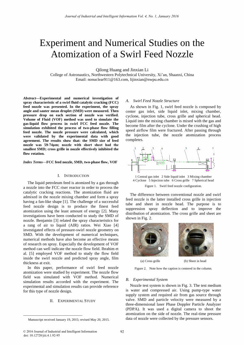
The difference between conventional nozzle and swirl
feed nozzle is the latter installed cross grille in injection
tube and sheet in nozzle head. The purpose is to
suppression spray deflection and to improve the
distribution of atomization. The cross grille and sheet are
shown in Fig. 2.
(a) Cross grille (b) Sheet in head
Figure 2. Note how the caption is centered in the column.
B. Experimental System
Nozzle test system is shown in Fig. 3. The test medium
is water and compressed air. Using pump-type water
supply system and required air from gas source through
valve. SMD and particle velocity were measured by a
three-dimensional laser Phase Doppler Particle Analyzer
(PDPA). It was used a digital camera to shoot the
atomization on the side of nozzle. The real-time pressure
data of nozzle were collected by the pressure sensors.
Journal of Industrial and Intelligent Information Vol. 4, No. 1, January 2016
© 2016 Journal of Industrial and Intelligent Informationdoi: 10.12720/jiii.4.1.92-95
92
Photomultiplier
Gas T
an
k
Reservoir
Signal
Processing UnitAcquisition
System
Laser Optical DriveOptical Fiber
Control System
Swirl Feed Nozzle
Pressure Sensors
Flo
wm
eter
Receiving Lens
Emission
Lens
Pump
Valv
eC
ut-o
ff
Valv
e
Surg
e
Tan
k
Figure 3. Experiment system of feed nozzle.
In the experiments, there were five different new feed
nozzle configurations, as shown in Table I. And in the
middle of spray we tested the nozzle on design conditions
(water flow 20T/h, air flow 1T/h). Test condition
parameters in the experiments are close to practical
application parameters. Laser measured point located on
the axis at the center of 800mm from the nozzle outlet,
which position is the point of contact of catalyst and oil
flow in the pipeline in actual production [6].
TABLE I. EXPERIMENTAL CONDITIONS
Nozzle number Nozzle head form Cross grille position
1# Short sheet head None
2# Long sheet head None
3# Original head Front of tube
4# Original head Middle of tube
5# Original head End of tube
C. Experimental Results and Analysis
Table II shows the different configurations of the
nozzle SMD and particle velocities. Installation of the
cross grille and the sheet in head result in increased of the
atomization particle diameters, because the cross grille
and the sheet lead to pressure drop, then a portion of the
pressure potential is consumed. Overall, the losses caused
by the cross grille greater than sheet and liquid particle
diameters increase the most. The SMD of nozzle installed
of short sheet is smaller than installation of long sheet
about 4μm. The longer sheet, the pressure potential is
consumed more. Therefore, it is effected on the
atomization particle diameters. That should be pay
attention to nozzle design. The position of cross grille is
also great impact on SMD, particularly in the central
region of atomization. In comparison, the front position is
best, the end of injection tube is worst. In the central
region of atomization, the SMD of nozzle installed of the
front of cross grille is smaller than the end of position
about 8.5μm. Basically, comparing with SMD, the nozzle
installed sheet is better than the nozzle installed cross
grille. But the particle velocities are contrary, the
installation of sheet is larger. Nozzle spray velocity
should not be excessive. Based on past experience in
engineering, when the spray particle velocities are higher
than 60m/s, the jet will affect catalyst [6].
TABLE II. EXPERIMENTAL RESULTS
Nozzle number
SMD(μm) Particle
velocity(m·s-1) Spray angle(°)
1# 59.22 28.43 112
2# 63.19 29.23 113
3# 65.57 25.23 109
4# 67.79 25.91 108
5# 74.02 20.92 111
The main factor affecting the spray angle is the
expansion angle of nozzle outlet. In addition to that there
is gas and liquid flow ratio. The nozzle head outlet is a
rectangular slot which expansion angle is 100°. On the
experimental situation, the length of sheet and the
position of cross grille have less influence on spray angle.
In general, the larger spray angle, the spray is effected
more strongly by surrounding air, and the atomization
particle diameters become smaller [7]. But FCC process
require spray angle is not too large, because the spray will
be jet at the edge of riser reactor, so the oil just adhere to
the wall that is unfavorable reactions.
Two-phase flow pressure drop in the nozzle is one of
the important parameter concerned by designer. The
system pressure drop determines the power required. The
lower total pressure drop, the energy is consumed fewer.
Table III shows the pressure drops of nozzle in test, in
each case the total pressure drops are similar. But the
pressure drop inside the nozzle segments depending on
whether the nozzle install with the cross grille or the
sheet. The cross grille results in significantly lower
pressure drop on cyclone and increases pressure drop on
injection tube and spherical head, while the position of
cross grille is little effect on nozzle pressure drop.
TABLE III. PRESSURE DROP OF NOZZLE
Nozzle
number
Liquid
inlet (MPa)
Cyclone
(MPa)
Injection
tube (MPa)
Head
(MPa)
Total
(MPa)
1# 0.077 0.076 0.091 0.155 0.399
2# 0.076 0.074 0.109 0.135 0.394
3# 0.074 0.066 0.139 0.132 0.411
4# 0.074 0.063 0.115 0.135 0.387
5# 0.079 0.064 0.111 0.131 0.385
III. NUMERICAL SIMULATION
A. Physical Model
In the calculation, consider the nozzle spray process
about two-phase flow through the cyclone from the
mixing chamber, ignoring the structure of the external
cavity. In the cyclone, using unstructured tetrahedral
meshes, and the remaining parts are structured by
hexahedral meshes. Inlet boundary condition is mass flow
inlet and outlet boundary condition is pressure outlet. The
back pressure set to atmospheric pressure.
B. Mathematical Model
Swirl nozzle internal flow is a typical gas-liquid flow.
To correct expression of surface tension at the interface
of two-phase, gas-liquid interface needs to be tracked and
Journal of Industrial and Intelligent Information Vol. 4, No. 1, January 2016
93© 2016 Journal of Industrial and Intelligent Information
described. Gas-liquid interface use VOF method to
determine.
Assuming the fluid is incompressible, the control
equations are
0
(1)
21P
t (2)
In the equations,
is velocity vector, is density, P
is pressure, is motion viscosity coefficient.
VOF method is introduced parameter C represented the
volume percent of liquid in unit control body
10
1
0
C
C (3)
Volume fraction equation
0
Ft
F (4)
C. Mathematical Model
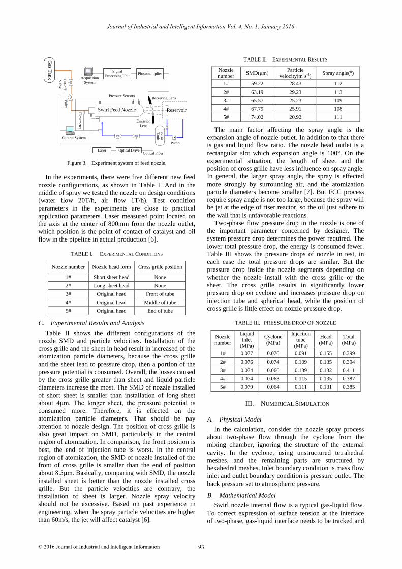
Nozzle is a unit realizing the liquid atomization, which
structure has great impact on the initial atomization
parameters. Studying internal flow characteristics inside
the nozzle has a lot of sense to atomization initial
parameters [8]. Fig. 4 shows the process of two-phase
flow filling nozzle. At 20ms initial two-phase flow fills
cyclone. After 30ms two-phase flow through the cyclone
trough and close to the wall reached at the middle of the
injection tube. Affected by the cyclone configuration,
there is an annular flow in the injection tube with an air
vortex at 40ms. When 60ms the fluid begins to eject from
the nozzle. Impacted by hemispherical nozzle head, spray
flow converge toward the center. But the nozzle is
different from conventional swirler. It will not form a
stable annular flow and air vortex, and has variety of fluid
state in the injection tube. After 140ms the air vortex
gradually disappears, fan-shaped spray has been basically
expanded. At 200ms the flow field comes to a steady
state and fan-shaped spray fully expands.
Figure 4. Process of two-phase flow filling nozzle.
Cyclone forces two-phase flow rotation which get the
circumferential direction of velocity. Due to the impact of
the cyclone, so that the flow in the nozzle is complex. Fig.
5 is flow stream chart after the nozzle flow is steady.
Looked forward from the nozzle inlet, two-phase flow
inside the nozzle rotates very obviously. Fig. 6 is flow
streamlines of nozzle installed cross grille. It can be seen
that cross grille inhibit rotational flow clearly, and flow
streamlines passed through cross grille are very straight.
In the injection tube diameter and tangential velocity
basically become zero. Moreover, the sheet in nozzle
head also inhibits the rotational flow as shown in Fig. 7.
Figure 5. Streamlines of original nozzle.
Figure 6. Streamlines of cross grille nozzle.
Figure 7. Streamlines of sheet nozzle.
1# nozzle
2# nozzle
3# nozzle
Journal of Industrial and Intelligent Information Vol. 4, No. 1, January 2016
94© 2016 Journal of Industrial and Intelligent Information
4# nozzle
5# nozzle
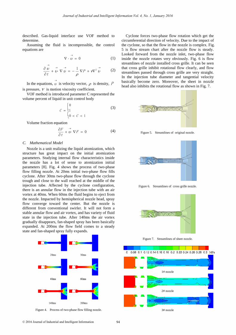
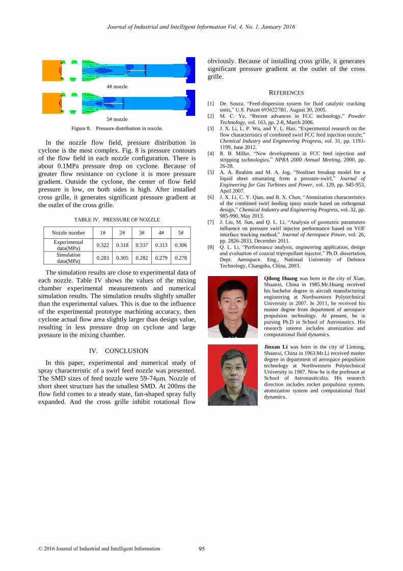
Figure 8. Pressure distribution in nozzle.
In the nozzle flow field, pressure distribution in
cyclone is the most complex. Fig. 8 is pressure contours
of the flow field in each nozzle configuration. There is
about 0.1MPa pressure drop on cyclone. Because of
greater flow resistance on cyclone it is more pressure
gradient. Outside the cyclone, the center of flow field
pressure is low, on both sides is high. After installed
cross grille, it generates significant pressure gradient at
the outlet of the cross grille.
TABLE IV. PRESSURE OF NOZZLE
Nozzle number 1# 2# 3# 4# 5#
Experimental data(MPa)
0.322 0.318 0.337 0.313 0.306
Simulation
data(MPa) 0.283 0.305 0.282 0.279 0.278
The simulation results are close to experimental data of
each nozzle. Table IV shows the values of the mixing
chamber experimental measurements and numerical
simulation results. The simulation results slightly smaller
than the experimental values. This is due to the influence
of the experimental prototype machining accuracy, then
cyclone actual flow area slightly larger than design value,
resulting in less pressure drop on cyclone and large
pressure in the mixing chamber.
IV. CONCLUSION
In this paper, experimental and numerical study of
spray characteristic of a swirl feed nozzle was presented.
The SMD sizes of feed nozzle were 59-74μm. Nozzle of
short sheet structure has the smallest SMD. At 200ms the
flow field comes to a steady state, fan-shaped spray fully
expanded. And the cross grille inhibit rotational flow
obviously. Because of installing cross grille, it generates
significant pressure gradient at the outlet of the cross
grille.
REFERENCES
[1] De. Souza, “Feed-dispersion system for fluid catalytic cracking units,” U.S. Patent 6936227B1, August 30, 2005.
[2] M. C. Ye, “Recent advances in FCC technology,” Powder
Technology, vol. 163, pp. 2-8, March 2006. [3] J. X. Li, L. P. Wu, and Y. L. Han, “Experimental research on the
flow characteristics of combined swirl FCC feed injection nozzle,” Chemical Industry and Engineering Progress, vol. 31, pp. 1193-
1199, June 2012.
[4] R. B. Miller, “New developments in FCC feed injection and stripping technologies,” NPRA 2000 Annual Meeting, 2000, pp.
26-28. [5] A. A. Ibrahim and M. A. Jog, “Nonliner breakup model for a
liquid sheet emanating from a pressure-swirl,” Journal of
Engineering for Gas Turbines and Power, vol. 129, pp. 945-953, April 2007.
[6] J. X. Li, C. Y. Qian, and B. X. Chen, “Atomization characteristics of the combined swirl feeding spray nozzle based on orthogonal
design,” Chemical Industry and Engineering Progress, vol. 32, pp.
985-990, May 2013. [7] J. Liu, M. Sun, and Q. L. Li, “Analysis of geometric parameters
influence on pressure swirl injector performance based on VOF interface tracking method,” Journal of Aerospace Power, vol. 26,
pp. 2826-2833, December 2011.
[8] Q. L. Li, “Performance analysis, engineering application, design and evaluation of coaxial tripropellant injector,” Ph.D. dissertation,
Dept. Aerospace. Eng., National University of Defence Technology, Changsha, China, 2003.
Qilong Huang was born in the city of Xian, Shaanxi, China in 1985.Mr.Huang received
his bachelor degree in aircraft manufacturing engineering at Northwestern Polytechnical
University in 2007. In 2011, he received his
master degree from department of aerospace propulsion technology. At present, he is
pursing Ph.D in School of Astronautics. His research interest includes atomization and
computational fluid dynamics.
Jinxan Li was born in the city of Lintong,
Shaanxi, China in 1963.Mr.Li received master degree in department of aerospace propulsion
technology at Northwestern Polytechnical
University in 1987. Now he is the professor at School of Astronauticshis. His research
direction includes rocket propulsion system,
atomization system and computational fluid
dynamics.
Journal of Industrial and Intelligent Information Vol. 4, No. 1, January 2016
95© 2016 Journal of Industrial and Intelligent Information