Embed Size (px)
Citation preview
EEM471 ELECTRICAL MACHINERY LABORATORY / EXPERIMENT VIII
1
Instructor : Assist. Prof. Dr. Sener AGALAR
TA : Res. Asst. H. Ersin EROL
ANADOLU UNIVERSITY
DEPT. OF ELECTRICAL AND ELECTRONICS
ENGINEERING
EEM 471 ELECTRICAL MACHINERY
LABORATORY
EXPERIMENT VIII
Polyexcitation Direct Current (DC) Machine
• Measuring the Winding Resistances
• Measuring the Mechanical and Iron Losses
EEM471 ELECTRICAL MACHINERY LABORATORY / EXPERIMENT VIII
2
1 - THE DIRECT CURRENT MACHINE
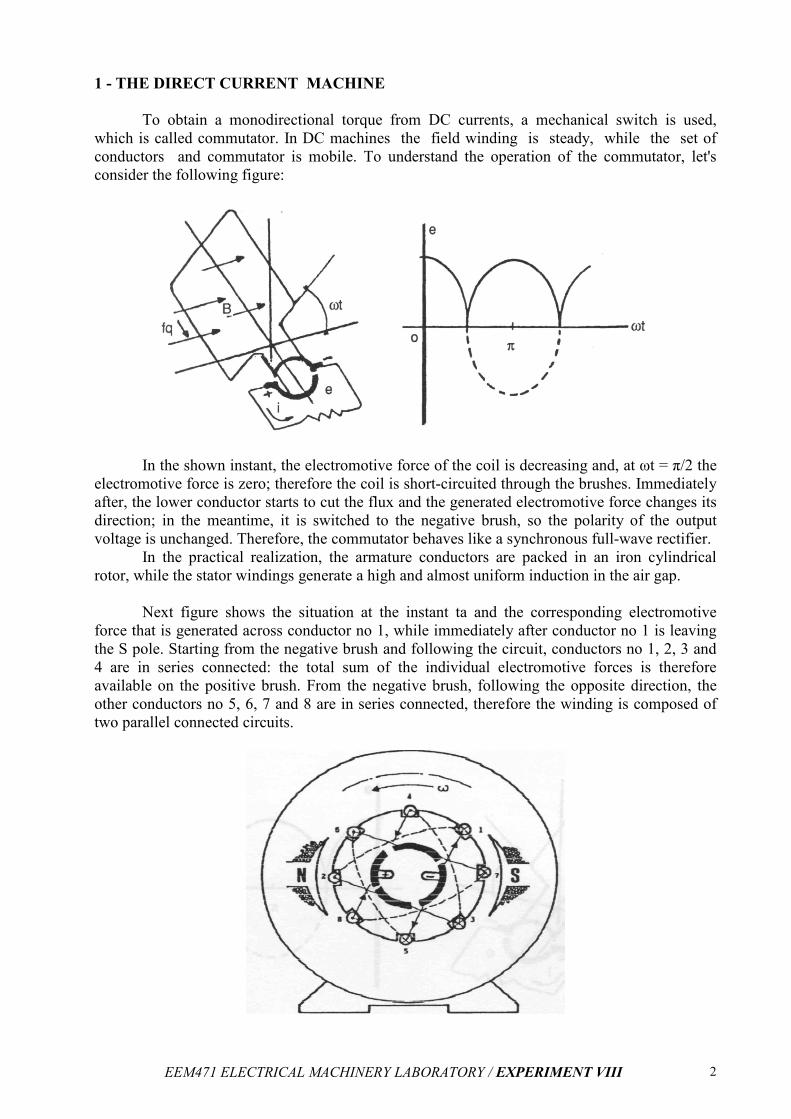
To obtain a monodirectional torque from DC currents, a mechanical switch is used,
which is called commutator. In DC machines the field winding is steady, while the set of
conductors and commutator is mobile. To understand the operation of the commutator, let's
consider the following figure:
In the shown instant, the electromotive force of the coil is decreasing and, at ωt = π/2 the
electromotive force is zero; therefore the coil is short-circuited through the brushes. Immediately
after, the lower conductor starts to cut the flux and the generated electromotive force changes its
direction; in the meantime, it is switched to the negative brush, so the polarity of the output
voltage is unchanged. Therefore, the commutator behaves like a synchronous full-wave rectifier.
In the practical realization, the armature conductors are packed in an iron cylindrical
rotor, while the stator windings generate a high and almost uniform induction in the air gap.
Next figure shows the situation at the instant ta and the corresponding electromotive
force that is generated across conductor no 1, while immediately after conductor no 1 is leaving
the S pole. Starting from the negative brush and following the circuit, conductors no 1, 2, 3 and
4 are in series connected: the total sum of the individual electromotive forces is therefore
available on the positive brush. From the negative brush, following the opposite direction, the
other conductors no 5, 6, 7 and 8 are in series connected, therefore the winding is composed of
two parallel connected circuits.
EEM471 ELECTRICAL MACHINERY LABORATORY / EXPERIMENT VIII
3
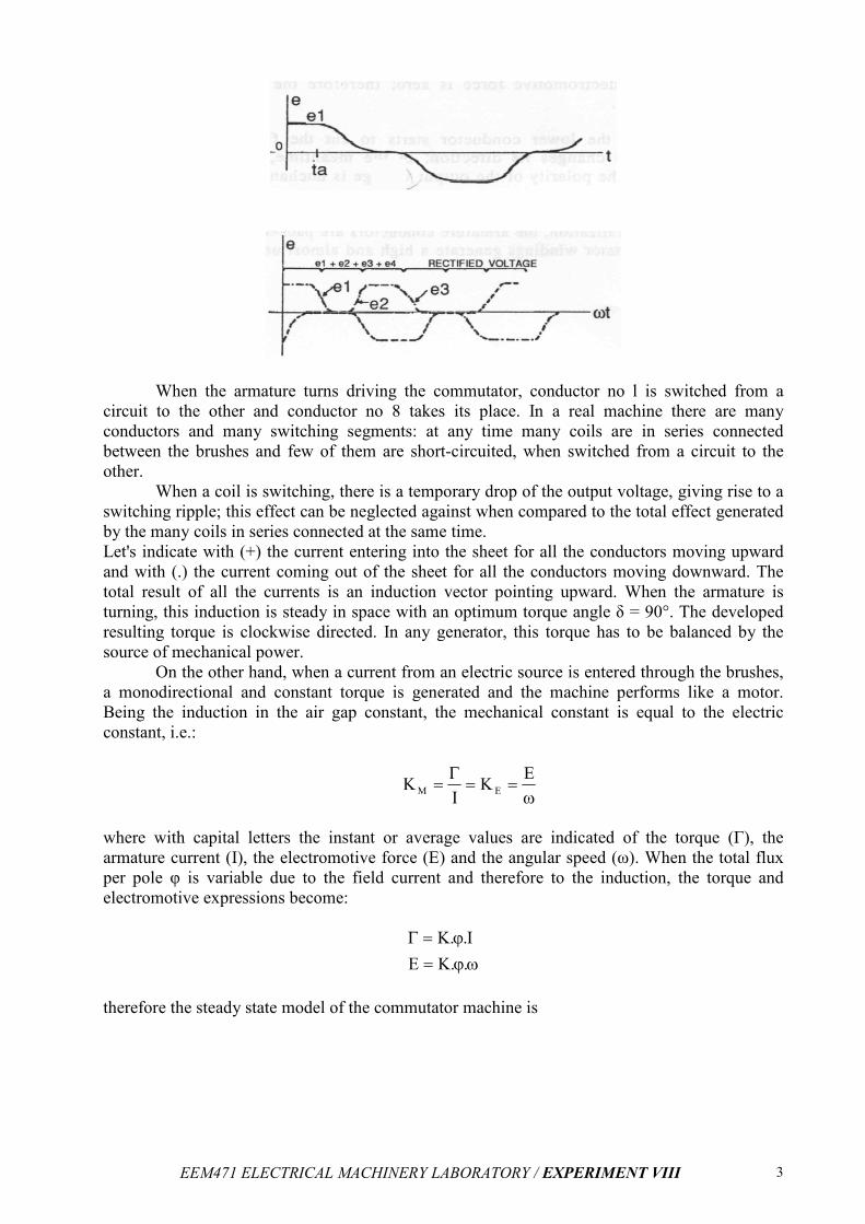
When the armature turns driving the commutator, conductor no l is switched from a
circuit to the other and conductor no 8 takes its place. In a real machine there are many
conductors and many switching segments: at any time many coils are in series connected
between the brushes and few of them are short-circuited, when switched from a circuit to the
other.
When a coil is switching, there is a temporary drop of the output voltage, giving rise to a
switching ripple; this effect can be neglected against when compared to the total effect generated
by the many coils in series connected at the same time.
Let's indicate with (+) the current entering into the sheet for all the conductors moving upward
and with (.) the current coming out of the sheet for all the conductors moving downward. The
total result of all the currents is an induction vector pointing upward. When the armature is
turning, this induction is steady in space with an optimum torque angle δ = 90°. The developed
resulting torque is clockwise directed. In any generator, this torque has to be balanced by the
source of mechanical power.
On the other hand, when a current from an electric source is entered through the brushes,
a monodirectional and constant torque is generated and the machine performs like a motor.
Being the induction in the air gap constant, the mechanical constant is equal to the electric
constant, i.e.:
ω==
Γ=
EK
IK EM
where with capital letters the instant or average values are indicated of the torque (Γ), the
armature current (I), the electromotive force (E) and the angular speed (ω). When the total flux
per pole φ is variable due to the field current and therefore to the induction, the torque and
electromotive expressions become:
ωϕ=
ϕ=Γ
..KE
I..K
therefore the steady state model of the commutator machine is
EEM471 ELECTRICAL MACHINERY LABORATORY / EXPERIMENT VIII
4
In the steady state, the terms associated to the energy accumulation aren't considered;
only the mechanical friction due to rotation (DR) and the electric resistance (R) are considered.
The value of K is a function of the machine construction and of the electric connections
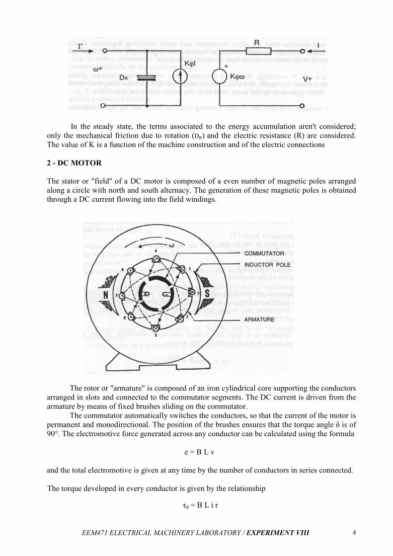
2 - DC MOTOR
The stator or "field" of a DC motor is composed of a even number of magnetic poles arranged
along a circle with north and south alternacy. The generation of these magnetic poles is obtained
through a DC current flowing into the field windings.
The rotor or "armature" is composed of an iron cylindrical core supporting the conductors
arranged in slots and connected to the commutator segments. The DC current is driven from the
armature by means of fixed brushes sliding on the commutator.
The commutator automatically switches the conductors, so that the current of the motor is
permanent and monodirectional. The position of the brushes ensures that the torque angle δ is of
90°. The electromotive force generated across any conductor can be calculated using the formula
e = B L v
and the total electromotive is given at any time by the number of conductors in series connected.
The torque developed in every conductor is given by the relationship
τd = B L i r
EEM471 ELECTRICAL MACHINERY LABORATORY / EXPERIMENT VIII
5
and the total torque is given by the contribution of the individual conductors. For a DC machine in steady state condition, the fundamental relationships are the following:
d A
E K. .
K. .I
= ϕω
Γ = ϕ
where:
E = electromotive force (V) φ = flux per pole in the air gap (Wb) ω = angular speed (rad/sec) Γd = torque (Nm) IA = armature current (A) K = constant of the machine
The fundamental relationships are referred to the iron gap: the voltage across the
terminals is different from the electromotive force due to the voltage drop across the armature
resistance; the torque on the shaft is different from the torque due to mechanical friction.
The DC machine is a dual side energy converter; therefore, in the air gap the mechanical
power is equal to the electric power:
Γd ω = E IA
The power in the air gap only represents the reversible part of the energy
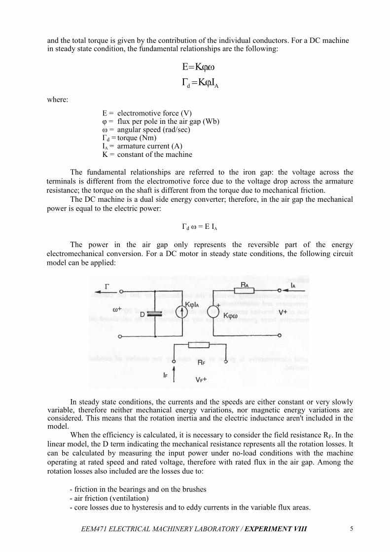
electromechanical conversion. For a DC motor in steady state conditions, the following circuit
model can be applied:
In steady state conditions, the currents and the speeds are either constant or very slowly variable, therefore neither mechanical energy variations, nor magnetic energy variations are considered. This means that the rotation inertia and the electric inductance aren't included in the model.
When the efficiency is calculated, it is necessary to consider the field resistance RF. In the
linear model, the D term indicating the mechanical resistance represents all the rotation losses. It
can be calculated by measuring the input power under no-load conditions with the machine
operating at rated speed and rated voltage, therefore with rated flux in the air gap. Among the
rotation losses also included are the losses due to:
- friction in the bearings and on the brushes
- air friction (ventilation)
- core losses due to hysteresis and to eddy currents in the variable flux areas.
EEM471 ELECTRICAL MACHINERY LABORATORY / EXPERIMENT VIII
6
The RA term is an equivalent resistance for considering the DC resistance of the armature
winding, the effect of non uniform distribution of the current in the armature conductors, the
contact losses of the brushes and the resistance of the auxiliary windings in the armature circuit,
when available.
In the shown circuit model we can assume D, RA, RF and K to be constant; the model is
therefore linear. The electric characteristic of the machine is therefore established by the
relationship
A A A AV E I .R K. . I .R= + = j w+
and in given conditions, assuming the magnetic circuit to be linear, i.e. the flux to be
proportional to the field current, it follows that:
A AV I .R
K.
-w=
j
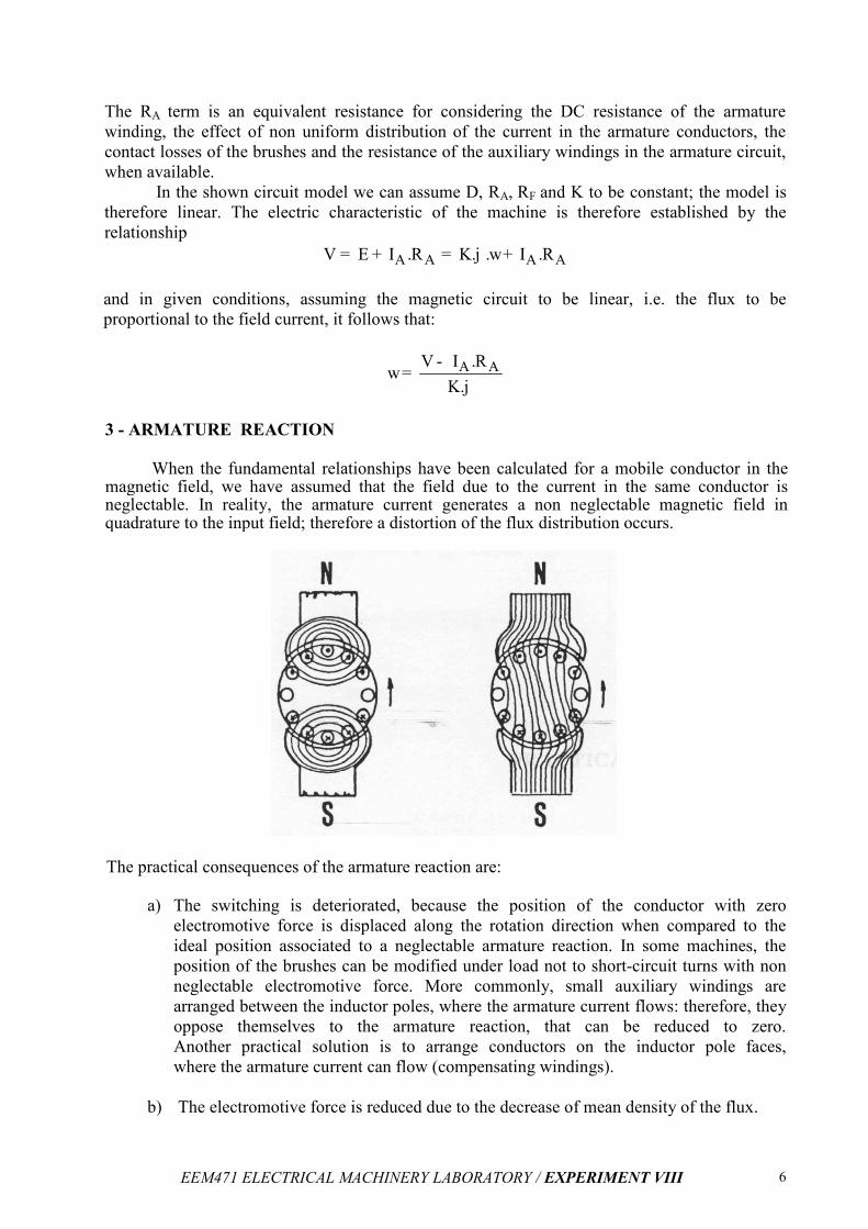
3 - ARMATURE REACTION
When the fundamental relationships have been calculated for a mobile conductor in the
magnetic field, we have assumed that the field due to the current in the same conductor is neglectable. In reality, the armature current generates a non neglectable magnetic field in quadrature to the input field; therefore a distortion of the flux distribution occurs.
The practical consequences of the armature reaction are: a) The switching is deteriorated, because the position of the conductor with zero
electromotive force is displaced along the rotation direction when compared to the
ideal position associated to a neglectable armature reaction. In some machines, the
position of the brushes can be modified under load not to short-circuit turns with non
neglectable electromotive force. More commonly, small auxiliary windings are
arranged between the inductor poles, where the armature current flows: therefore, they
oppose themselves to the armature reaction, that can be reduced to zero.
Another practical solution is to arrange conductors on the inductor pole faces,
where the armature current can flow (compensating windings).
b) The electromotive force is reduced due to the decrease of mean density of the flux.
EEM471 ELECTRICAL MACHINERY LABORATORY / EXPERIMENT VIII
7
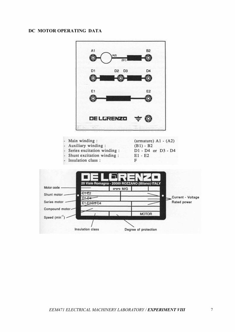
DC MOTOR OPERATING DATA
EEM471 ELECTRICAL MACHINERY LABORATORY / EXPERIMENT VIII
8
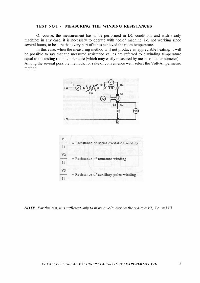
TEST NO 1 - MEASURING THE WINDING RESISTANCES
Of course, the measurement has to be performed in DC conditions and with steady
machine; in any case, it is necessary to operate with "cold" machine, i.e. not working since
several hours, to be sure that every part of it has achieved the room temperature.
In this case, when the measuring method will not produce an appreciable heating, it will
be possible to say that the measured resistance values are referred to a winding temperature
equal to the testing room temperature (which may easily measured by means of a thermometer).
Among the several possible methods, for sake of convenience we'll select the Volt-Ampermetric
method.
NOTE: For this test, it is sufficient only to move a voltmeter on the position V1, V2, and V3
EEM471 ELECTRICAL MACHINERY LABORATORY / EXPERIMENT VIII
9
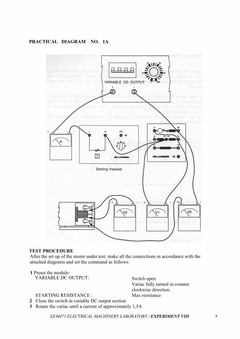
PRACTICAL DIAGRAM NO. 1A
TEST PROCEDURE
After the set up of the motor under test, make all the connections in accordance with the
attached diagrams and set the command as follows:
1 Preset the module: VARIABLE DC OUTPUT:
Switch open
Variac fully turned in counter
clockwise direction.
STARTING RESISTANCE : Max resistance
2 Close the switch in variable DC output section
3 Rotate the variac until a current of approximately 1,5A
EEM471 ELECTRICAL MACHINERY LABORATORY / EXPERIMENT VIII
10
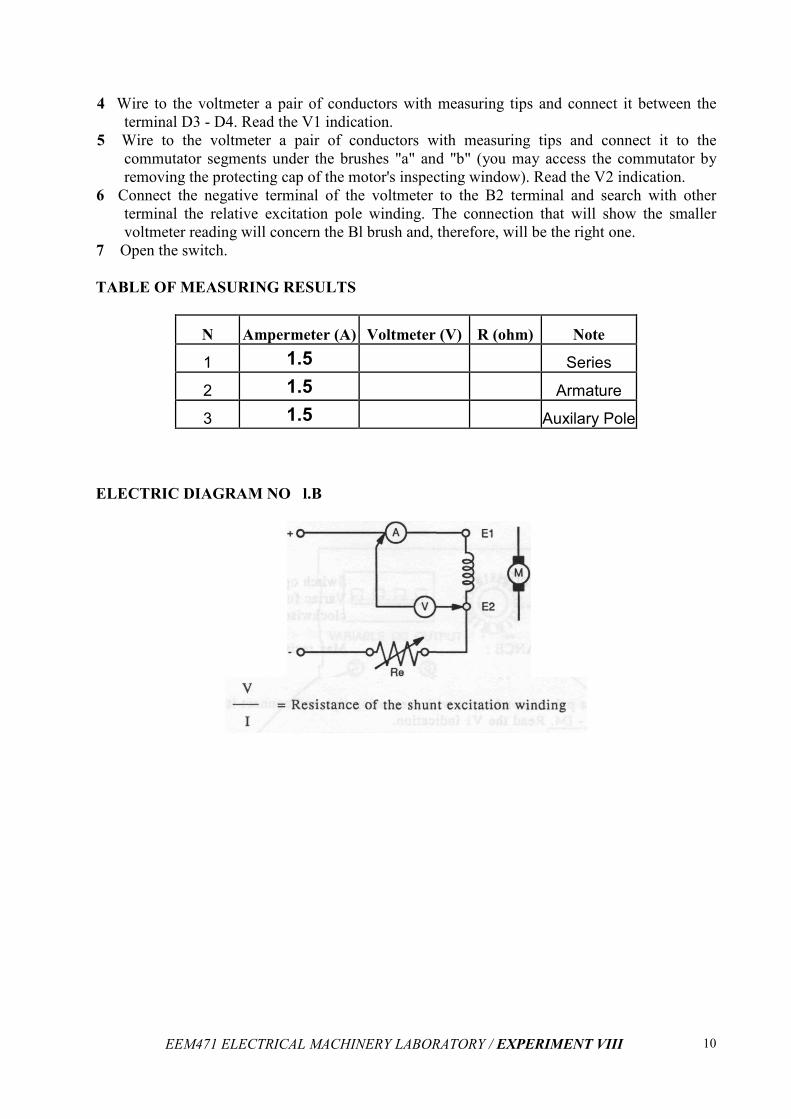
4 Wire to the voltmeter a pair of conductors with measuring tips and connect it between the
terminal D3 - D4. Read the V1 indication.
5 Wire to the voltmeter a pair of conductors with measuring tips and connect it to the
commutator segments under the brushes "a" and "b" (you may access the commutator by
removing the protecting cap of the motor's inspecting window). Read the V2 indication.
6 Connect the negative terminal of the voltmeter to the B2 terminal and search with other
terminal the relative excitation pole winding. The connection that will show the smaller
voltmeter reading will concern the Bl brush and, therefore, will be the right one.
7 Open the switch.
TABLE OF MEASURING RESULTS
N Ampermeter (A) Voltmeter (V) R (ohm) Note
1 1.5 Series
2 1.5 Armature
3 1.5 Auxilary Pole
ELECTRIC DIAGRAM NO l.B
EEM471 ELECTRICAL MACHINERY LABORATORY / EXPERIMENT VIII
11
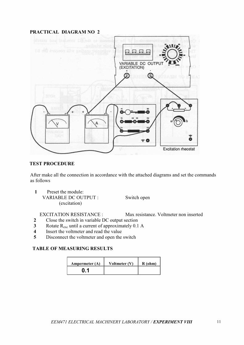
PRACTICAL DIAGRAM NO 2
TEST PROCEDURE
After make all the connection in accordance with the attached diagrams and set the commands
as follows
1 Preset the module:
VARIABLE DC OUTPUT :
(excitation)
EXCITATION RESISTANCE :
Switch open
Max resistance. Voltmeter non inserted
2 Close the switch in variable DC output section
3 Rotate Rexc until a current of approximately 0.1 A
4 Insert the voltmeter and read the value
5 Disconnect the voltmeter and open the switch
TABLE OF MEASURING RESULTS
Ampermeter (A) Voltmeter (V) R (ohm)
0.1
EEM471 ELECTRICAL MACHINERY LABORATORY / EXPERIMENT VIII
12
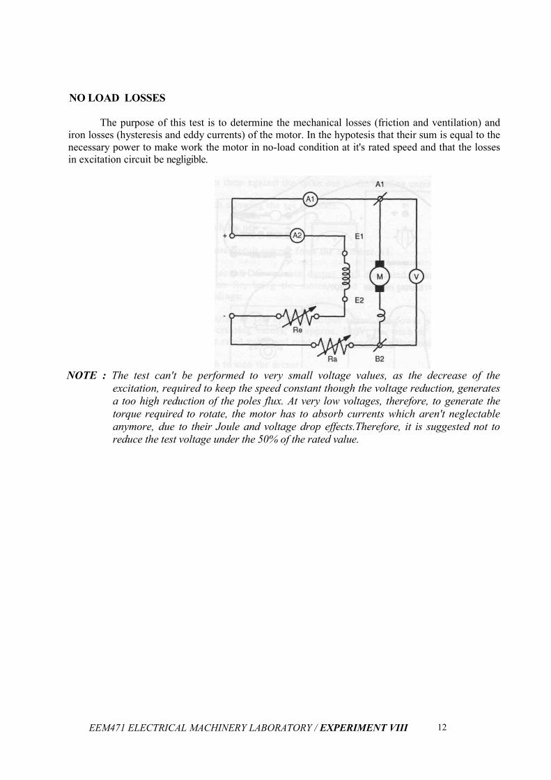
NO LOAD LOSSES
The purpose of this test is to determine the mechanical losses (friction and ventilation) and
iron losses (hysteresis and eddy currents) of the motor. In the hypotesis that their sum is equal to the
necessary power to make work the motor in no-load condition at it's rated speed and that the losses
in excitation circuit be negligible.
NOTE : The test can't be performed to very small voltage values, as the decrease of the
excitation, required to keep the speed constant though the voltage reduction, generates
a too high reduction of the poles flux. At very low voltages, therefore, to generate the
torque required to rotate, the motor has to absorb currents which aren't neglectable
anymore, due to their Joule and voltage drop effects.Therefore, it is suggested not to
reduce the test voltage under the 50% of the rated value.
EEM471 ELECTRICAL MACHINERY LABORATORY / EXPERIMENT VIII
13
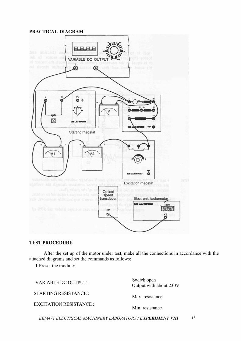
PRACTICAL DIAGRAM
TEST PROCEDURE
After the set up of the motor under test, make all the connections in accordance with the
attached diagrams and set the commands as follows:
1 Preset the module:
VARIABLE DC OUTPUT :
STARTING RESISTANCE :
EXCITATION RESISTANCE :
Switch open
Output with about 230V
Max. resistance
Min. resistance
EEM471 ELECTRICAL MACHINERY LABORATORY / EXPERIMENT VIII
14
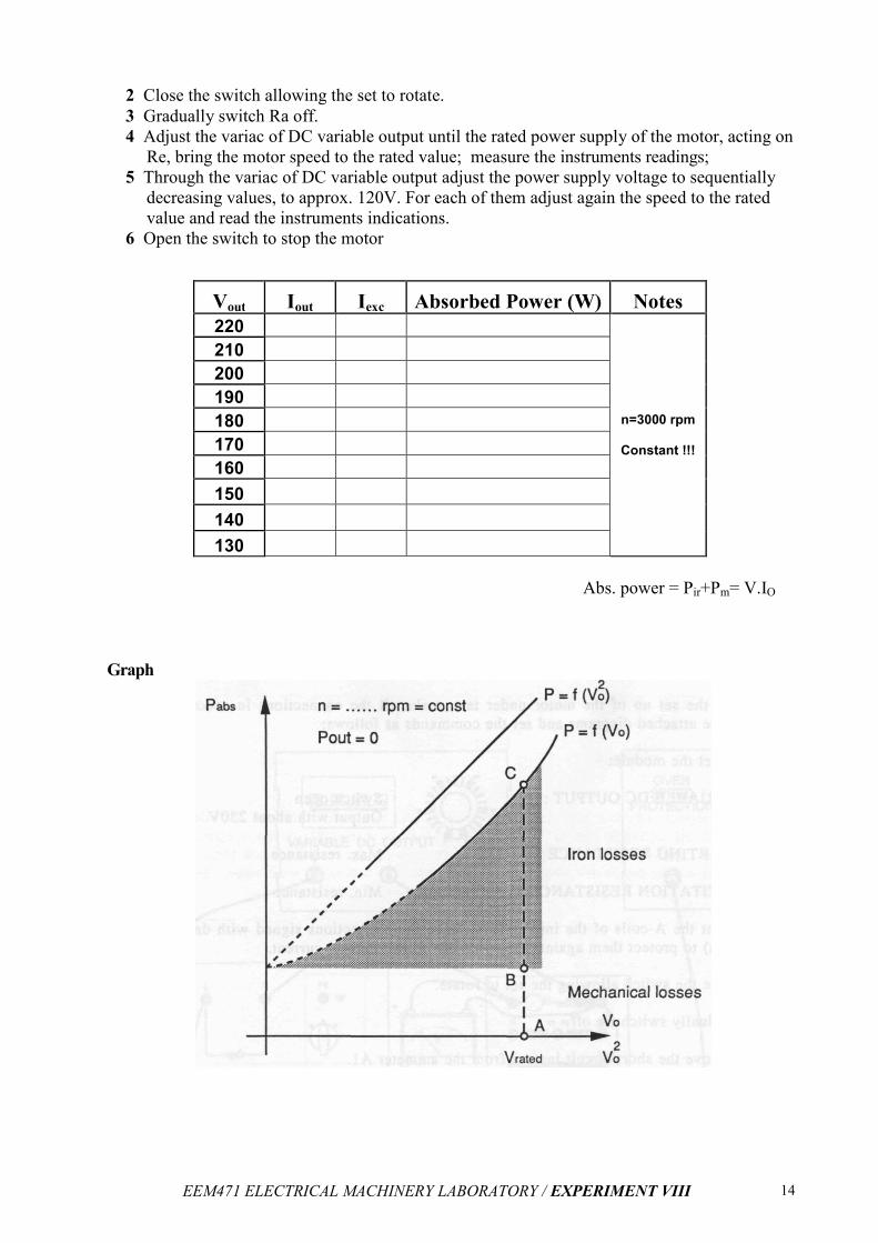
2 Close the switch allowing the set to rotate.
3 Gradually switch Ra off.
4 Adjust the variac of DC variable output until the rated power supply of the motor, acting on
Re, bring the motor speed to the rated value; measure the instruments readings;
5 Through the variac of DC variable output adjust the power supply voltage to sequentially
decreasing values, to approx. 120V. For each of them adjust again the speed to the rated
value and read the instruments indications.
6 Open the switch to stop the motor
Vout Iout Iexc Absorbed Power (W) Notes
220
n=3000 rpm
Constant !!!
210
200
190
180
170
160
150
140
130
Abs. power = Pir+Pm= V.IO
Graph
EEM471 ELECTRICAL MACHINERY LABORATORY / EXPERIMENT VIII
15
NOTES : Drawing in the diagram the absorbed power as a function of the voltage, an almost parabolic curve is obtained, which has an offset with respect to the axis origin.
The ordinate of the curve's origin isn't experimentally measurable, but can be obtained by graphic extrapolation from the measured section of the curve (heavy section).As this extrapolation isn't always simple, a graphic contrivance may be followed, showing the absorbed power as a function of V (exp2) instead of V.
In this way, the graph parabola will be converted into a straight line, which may be easily extrapolated. The ordinate of the origin determines, due to the reasons described in "Theoretic background", the value of the mechanical losses. The remaining section of the curve, therefore, will represent the iron losses (which
vary following an almost quadratic relationship with the power supply voltage). At the
rated voltage it is possible to obtain:
AB = mechanical losses = .... W = ...... % of rated power
BC = iron losses = .... W =...... % of rated power