Embed Size (px)
Citation preview
Experimental Analysis of Mechanical Properties of
Composite Material Reinforced by Aluminium-Synthetic
Fibers
Husain Mehdi1, Anil Kumar1, Arshad Mahmood2, Manoj Saini1
1Department of Mechanical Engineering, Meerut Institute of Technology,
Meerut (U.P). INDIA 2Department of Mechanical Engineering, ZHCET, AMU, Aligarh (U.P).
INDIA
Abstract: Composite materials are engineering materials made from two or more constituent materials
that remain separate and distinct on a macroscopic level while forming a single component. In this work
the mechanical properties of GFRP (glass Fiber Reinforcement Plastic), Nylon and their composite with
aluminium were evaluated with reference to ASTM D638-02 a. During the tensile load, the maximum
strain, and stress are obtained. The maximum strength is found in composite GFRP instead of
Aluminium and composite Nylon. Composite material has shown an improvement of mechanical
properties when compared with individual materials.
Keywords: GFRP, Nylon, Aluminium, Tensile Strength, Strain
1 Introduction
Many of our modern technologies require materials with unusual combination of properties that cannot
be met by the conventional materials [1]. Many composite materials are composed of just two phases one
is termed the matrix, which is continuously surrounded by the other phase, often called the dispersed
phase [2]. Recently an increasing use of composites reinforced with different types of fibers has occurred,
owing the following advantages: they are strong enough, light in weight, abundant, non-abrasive and
cheap [3].The damage tolerance of polymeric materials can be enhanced by improving the inter laminar
properties of the polymer composites [4]. Fiber is known as material which strengthens the composites.
For decades, fiber has been used to increase toughness and tensile ductility. Some innovations have been
applied such as Fiber Reinforced Concrete (FRC) High Performance Fiber Reinforced Cementitious
Composites (HPRFCC) which is known as Engineered Cementitious Composites (ECC). It is important
to conduct study to know the performance of fiber in cementitious matrix. The properties of interfaces
between fiber and cementitious matrices and their stress transfer takes an important role in determining
the whole composites properties, selecting the main ingredients of composites, and predicting the failure
of composite. The majority of engineering composites materials in demanding applications consists of
continuous fibers of glass or carbon reinforcement in thermosetting epoxy polymer. There has been a
tremendous advancement in recent days. Compared to metals, the polymeric composites have many
advantages as higher fatigue strength, higher corrosion resistance and lower weight [5,6] polymeric
composites are susceptible to mechanical damages when they are subjected to efforts of tension, flexural,
compression which can lead to material failure. Therefore it is necessary to use materials with higher
damage tolerance & carryout an adequate mechanical evaluation. Damage tolerance of epoxy polymeric
composites can be enhanced by improving the inter laminar properties by toughening matrix [7],
reinforcement with bidirectional woven fabrics [8]. The basic concepts of composites material along with
details of earlier works are explained by author at reference [9]. Harish et al. [11] developed coir
composite and mechanical properties were evaluated. Scanning electron micrographs obtained from
fracture surfaces were used for a qualitative evaluation of the interfacial properties of coir /epoxy and
compared with glass fibers. Wang and Huang [12] had taken a coir fiber stack characters of the fibers
were analyzed. Length of the fibers was in the range between 8 and 337 mm. The fibers amount with the
length range of 15~145 mm was 81.95% of all measured fibers. Weight of fibers with the length range of
35~225 mm accounted for 88.34% of all measurement. The average fineness of the coir fibers was 27.94
tex. Longer fibers usually had higher diameters. Composite boards were fabricated by using a heat press
machine with the coir fiber as the reinforcement and the rubber as matrix.
_____________________________________________________
The Corresponding author: [email protected]

International Journal of Mechanical Engineering ( IJME ) Volume 4 Issue 2, (Year 2014) ISSN : 2277-7059
http://www.ijmejournal.com
_____________________________________________________________________________________________________________
60
Tensile strength of the composites was investigated Materials and sample preparation. Nilza et al. [13]
use three Jamaican natural cellulosic fibers for the design and manufacture of composite material. They
took bagasse from sugar cane, banana trunk from banana plant and coconut coir from the coconut husk.
Samples were subjected to standardized tests such as ash and carbon content, water absorption, moisture
content, tensile strength, elemental analysis and chemical analysis.
In this work we used GFRP (Glass fiber reinforcement Plastic), Nylon and Aluminium. Mechanical
properties are evaluated for GFRP, Nylon and Aluminium individually and their composite with
aluminium, using specimens prepared with reference to ASTM D638-02 a [10]. Fig.1 shows typical
specimens for composite Al-GFRP-Al and Al-Nylon-Al.
(a) (b)
Figure 1:- Specimen of ASTM code D638-02 a (type II) (a) Composite Al-GFRP-Al, (b) Composite Al-Nylon-Al
[10]
2 Experimental Procedure
The composite specimens were subjected to various loads and computer controlled Universal Testing
Machine (UTM). The specimens were clamped and tests were performed. The tests were closely
monitored and conducted at room temperature. The load at which the completed fracture of the specimen
occurred has been accepted as breakage load. Fig.2 shows the test rig used in the experiments. Fig.3
shows the fractured specimens using the test rig of Figure.2.
Figure 2:- Tensile Test of Nylon Fiber on Digital UTM

International Journal of Mechanical Engineering ( IJME ) Volume 4 Issue 2, (Year 2014) ISSN : 2277-7059
http://www.ijmejournal.com
_____________________________________________________________________________________________________________
61
(a) (b)
Figure 3:- Fractured Specimens (a) Nylon, (b) GFRP [10]
Specification of Specimen:
All the specimens 1, 2 and 3are made with the help of ASTM code D638-02 a [10] and have the
characteristics.
For figure 5,6,7,8 and 9
Specimen 1: Aluminum (Type-I)
Specimen 2: Aluminum (Type-II).
Specimen 3: Aluminum (Type-III)
Similarly all the three specimens are made by Type-I, Type-II and Type-III for composite and their
individual materials.
Figure 4: Drawing of Specimen
International Journal of Mechanical Engineering ( IJME ) Volume 4 Issue 2, (Year 2014) ISSN : 2277-7059
http://www.ijmejournal.com
_____________________________________________________________________________________________________________
62
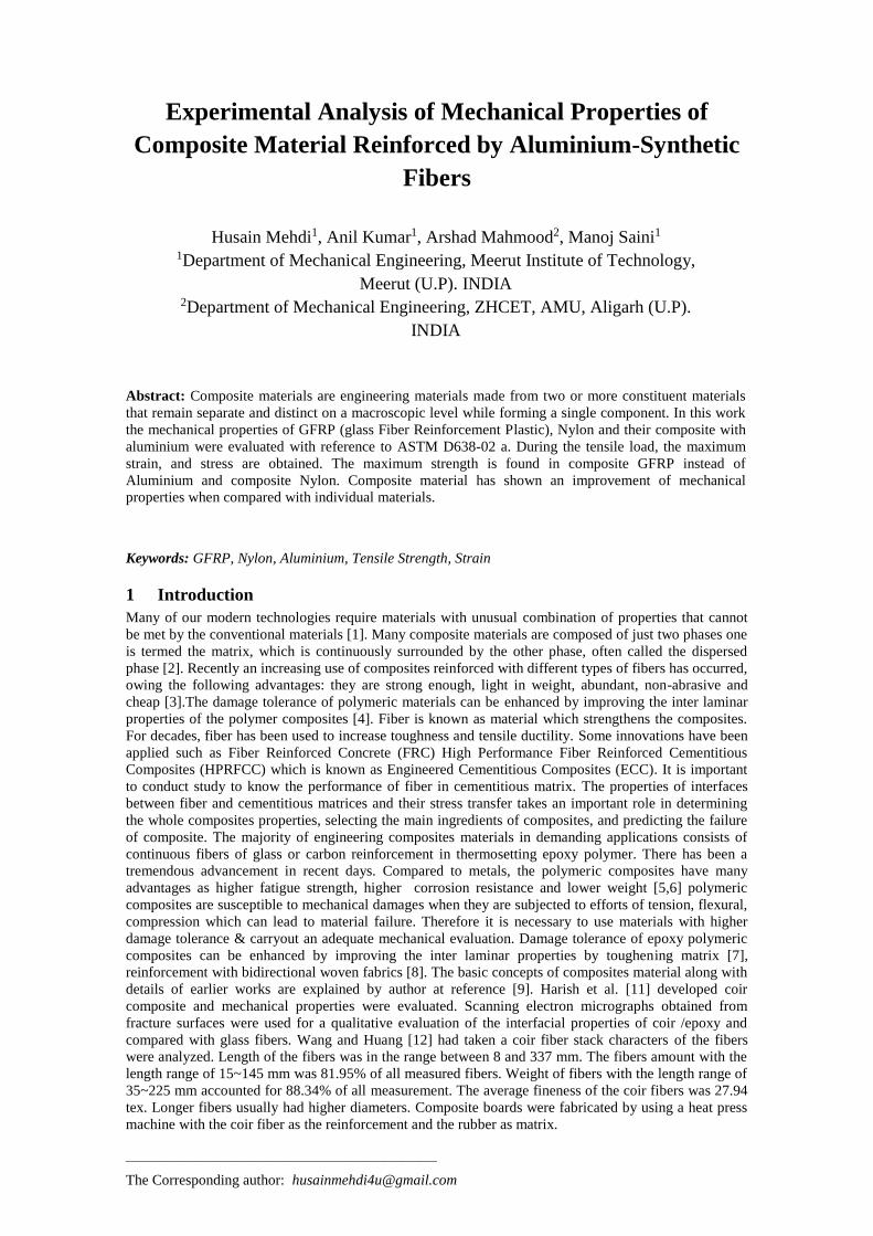
3 Results and Discussions
Table 1: Tensile properties of Al, GFRP, Nylon and their Composite
Material Specimen
Ultimate
Strength
(N/mm2)
Mean Ultimate
Strength
(N/mm2)
Strain Mean
Strain
1 155 0.376
Aluminium 2 162 158.33 0.314 0.340
3 158 0.33
1 39 0.572
Nylon 2 43 42 0.634 0.570
3 44 0.506
1 218 0.16
GFRP 2 213 217 0.156 0.157
3 220 0.156
1 128 1.8
Composite
Nylon 2 121 122.33 2.07 1.960
3 118 2.01
1 242 0.246
Composite
GFRP 2 246 239.33 0.222 0.229
3 230 0.220
Table 2:- Dimension of Specimen with ASTM code D638-02 a [10]
Specimen Dimensions mm
Dimension (See Drawing) Thickness 7 mm or less Over 7 to 14 mm
Type-I
(mm) Type-II(mm) Type- III (mm)
W- Width of Narrow section 13 6 19
L-Length of narrow section 57 57 57
WO-Width over all 19 19 29
LO Length over all 165 183 246
G-Gage length 50 50 50
D-Distance between
grips
115 135
115

International Journal of Mechanical Engineering ( IJME ) Volume 4 Issue 2, (Year 2014) ISSN : 2277-7059
http://www.ijmejournal.com
_____________________________________________________________________________________________________________
63
R-Radius of fillet 76 76 76
Figure-5 shows the engineering stress-strain curve for Aluminium specimens with an enlarged scale, now
showing strains from zero up to specimen fracture. Here it appears that the rate of strain hardening
diminishes up to UTS (Ultimate Tensile Strength).Beyond that point, the material appears to strain
soften, so that each increment of additional strain requires a smaller stress.
(a) (b)
(c)
Figure 5:- Stress Strain Diagram for Aluminum (a) Specimen-1, (b) Specimen-2, (c) Specimen-3
The apparent change from strain hardening to strain softening is an artefact of the plotting procedure,
however, as is the maximum observed in the curve at the UTS. The load must equal the true stress times
the actual area (P = σt A), and as long as strain hardening can increase σt enough to compensate for the
reduced area A, the load and therefore the engineering stress will continue to rise as the strain increases.
Eventually, however, the decrease in area due to flow becomes larger than the increase in true stress due
to strain hardening, and the load begins to fall.
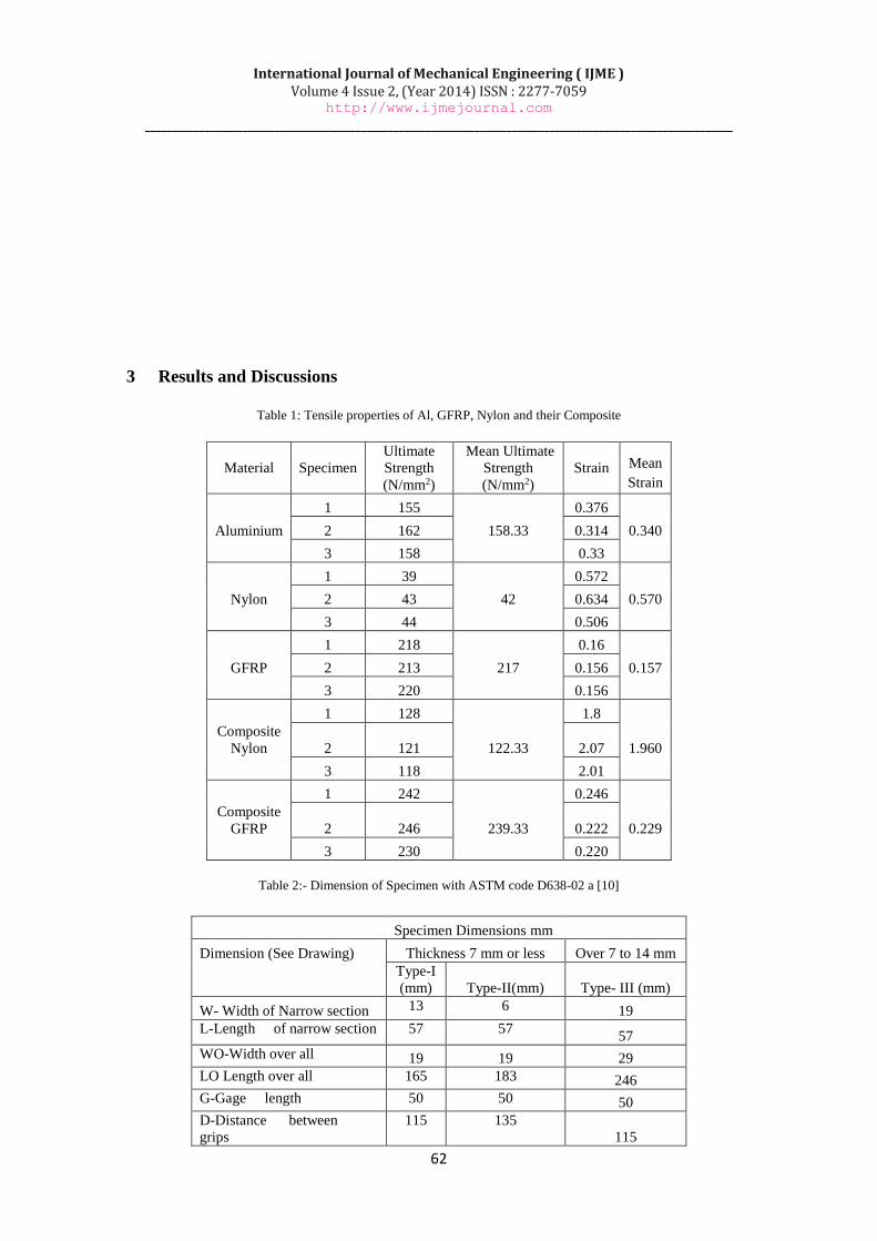
Figure 6 shows the stress strain curve for GFRP specimens, it shows similar behaviour as that of stress-
strain curve for aluminium up to UTS i.e. the rate of strain hardening diminishes up to UTS. But after this
point as the tensile load is increased the failure of GFRP take place resulting in sudden decrease in stress
with no or constant strain. But it is interesting to observe that the ultimate tensile strength of GFRP is
higher than that of pure aluminium but its strain is lesser.
International Journal of Mechanical Engineering ( IJME ) Volume 4 Issue 2, (Year 2014) ISSN : 2277-7059
http://www.ijmejournal.com
_____________________________________________________________________________________________________________
64
(a) (b)
(c)
Figure 6:- Stress Strain Diagram for GFRP (a) Specimen-1 (b) Specimen-2, (c) Specimen-3
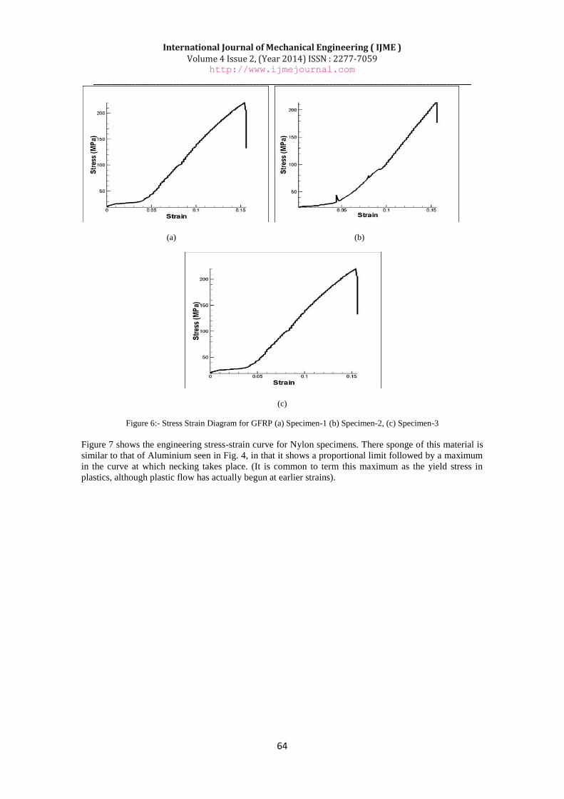
Figure 7 shows the engineering stress-strain curve for Nylon specimens. There sponge of this material is
similar to that of Aluminium seen in Fig. 4, in that it shows a proportional limit followed by a maximum
in the curve at which necking takes place. (It is common to term this maximum as the yield stress in
plastics, although plastic flow has actually begun at earlier strains).
International Journal of Mechanical Engineering ( IJME ) Volume 4 Issue 2, (Year 2014) ISSN : 2277-7059
http://www.ijmejournal.com
_____________________________________________________________________________________________________________
65
(a) (b)
(c)
Figure 7:- Stress Strain Diagram for Nylon (a) Specimen-1 (b) Specimen-2, (c) Specimen-3
The Nylon, however, differs dramatically from Aluminium in that the neck does not continue shrinking
until the specimen fails. Rather, the material in the neck stretches only to a “natural draw ratio” which is
a function of temperature and specimen processing, beyond which the material in the neck stops
stretching and new material at the neck shoulders necks down. The neck then propagates until it spans the
full gage length of the specimen, a process called drawing. Figure 8 shows the stress-strain curve for
Nylon composite specimens, it shows that up to UTS (Ultimate Tensile Strength) there is sudden increase
in stress with small increase in strain as up to this point there is large strain hardening on the layers of
aluminium. After UTS, as the tensile load increases, failure of the aluminium take place due to which
there is a sudden decrease in load indicating the failure of aluminium. After the failure of aluminium,
tensile load acts on nylon but as nylon is highly elastic material it keep on stretching with constant load.
Thus there is a straight line in the figure depicting the drawing of aluminium due to which strain goes on
increasing with a small change in stress.

International Journal of Mechanical Engineering ( IJME ) Volume 4 Issue 2, (Year 2014) ISSN : 2277-7059
http://www.ijmejournal.com
_____________________________________________________________________________________________________________
66
(a) (b)
(c)
Figure 8:- Stress Strain Diagram for Composite Nylon (a) Specimen-1 (b) Specimen-2, (c) Specimen-3
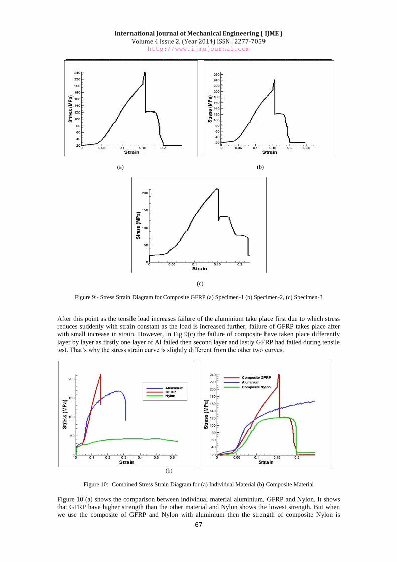
Figure 9 shows the stress strain curve for composite GFRP specimens, in all the graphs shows the similar
behaviour as that of aluminium just before the UTS in fig 9(a) & fig 9(b) but fig 9(c) behaves similarly as
aluminium up to UTS point. This could be due to variable conditions of testing so as the two curves 9(a)
& 9(b) are somewhat similar so we could analyze the mechanical properties of GFRP on the basis of
these two curves. Beyond a certain point in these two curves there is a sudden rise in load up to UTS this
is due to the fact that both aluminium and GFRP have high tensile strength.
International Journal of Mechanical Engineering ( IJME ) Volume 4 Issue 2, (Year 2014) ISSN : 2277-7059
http://www.ijmejournal.com
_____________________________________________________________________________________________________________
67
(a) (b)
(c)
Figure 9:- Stress Strain Diagram for Composite GFRP (a) Specimen-1 (b) Specimen-2, (c) Specimen-3
After this point as the tensile load increases failure of the aluminium take place first due to which stress
reduces suddenly with strain constant as the load is increased further, failure of GFRP takes place after
with small increase in strain. However, in Fig 9(c) the failure of composite have taken place differently
layer by layer as firstly one layer of Al failed then second layer and lastly GFRP had failed during tensile
test. That’s why the stress strain curve is slightly different from the other two curves.
(b)
Figure 10:- Combined Stress Strain Diagram for (a) Individual Material (b) Composite Material
Figure 10 (a) shows the comparison between individual material aluminium, GFRP and Nylon. It shows
that GFRP have higher strength than the other material and Nylon shows the lowest strength. But when
we use the composite of GFRP and Nylon with aluminium then the strength of composite Nylon is
International Journal of Mechanical Engineering ( IJME ) Volume 4 Issue 2, (Year 2014) ISSN : 2277-7059
http://www.ijmejournal.com
_____________________________________________________________________________________________________________
68
increased, and the strength of composite GFRP remain higher than the other composite as shown in
figure 10 (b).
(a)
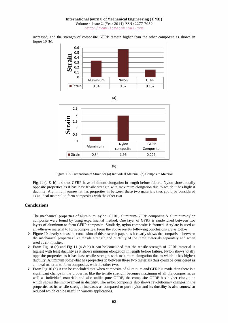
(b)
Figure 11:- Comparison of Strain for (a) Individual Material, (b) Composite Material
Fig 11 (a & b) it shows GFRP have minimum elongation in length before failure. Nylon shows totally
opposite properties as it has least tensile strength with maximum elongation due to which it has highest
ductility. Aluminium somewhat has properties in between these two materials thus could be considered
as an ideal material to form composites with the other two
Conclusions
The mechanical properties of aluminum, nylon, GFRP, aluminum-GFRP composite & aluminum-nylon
composite were found by using experimental method. One layer of GFRP is sandwiched between two
layers of aluminum to form GFRP composite. Similarly, nylon composite is formed. Acrylate is used as
an adhesive material to form composites. From the above results following conclusions are as follow
Figure 10 clearly shows the conclusion of this research paper, as it clearly shows the comparison between
the mechanical properties like tensile strength and ductility of the three materials separately and when
used as composites.
From Fig 10 (a) and Fig 11 (a & b) it can be concluded that the tensile strength of GFRP material is
highest with least ductility as it shows minimum elongation in length before failure. Nylon shows totally
opposite properties as it has least tensile strength with maximum elongation due to which it has highest
ductility. Aluminum somewhat has properties in between these two materials thus could be considered as
an ideal material to form composites with the other two.
From Fig 10 (b) it can be concluded that when composite of aluminum and GFRP is made then there is a
significant change in the properties like the tensile strength becomes maximum of all the composites as
well as individual materials and also unlike pure GFRP, the composite GFRP has higher elongation
which shows the improvement in ductility. The nylon composite also shows revolutionary changes in the
properties as its tensile strength increases as compared to pure nylon and its ductility is also somewhat
reduced which can be useful in various applications.
Aluminium Nylon GFRP
Strain 0.34 0.57 0.157
0
0.1
0.2
0.3
0.4
0.5
0.6
Str
ain
Aluminium Nylon
composite GFRP
Composite
Strain 0.34 1.96 0.229
0
0.5
1
1.5
2
2.5
Str
ain
International Journal of Mechanical Engineering ( IJME ) Volume 4 Issue 2, (Year 2014) ISSN : 2277-7059
http://www.ijmejournal.com
_____________________________________________________________________________________________________________
69
References
[1] B. Harris, Engineering composite Materials, The institute of materials London, 1999.
[2] M.R Piggott, load bearing fiber composites, Pergamon Press, Oxford , 1980
[3] P.C Powell, Engineering with fiber laminated composites, Chapman & Hall, London. 1994
[4] W.X Wang, Takao Y, Matsubara T, Kim HS “Fiber orientation and its effects” Comp. Sci. Tech.
62(6):767, 2002
[5] M.M. Schwartz, Composite Materials: Properties, Nondestructive Testing and Repair, V.1, Prentice-
Hall Inc., New Jersey, USA, 1997.
[6] A.A. Baker, P.J. Callus, S. Georgiadis, P.J. Falzon, S.E. Dutton and K.H. Leong, An affordable
methodology for replacing metallic aircraft panels with advanced composites, Composites: Part A,
33(2002), 687–696.
[7] N. Selaand and O. Ishai, Inter laminar fracture toughness and toughening of laminated composite
materials: A review, Composites, 20(20) (1989), 423–425.
[8] A. Mouritz, K. Leong and I. Herszberg, A review of the effect of stitching in the in plane mechanical
properties of fiber reinforced polymer composites, Composites: Part A, 28(12) (1997), 979–991.
[9] B.S. Hayes, E.N. Gilbert and J.C. Seferis, Scaling complications of dual temperature cure resin
prepreg systems in airplane part manufacture, Composites: Part A, 31(2000), 717–725.
[10] The jurisdiction of ASTM Committee D20 on Plastics and is the direct responsibility of
Subcommittee D20.10 on Mechanical Properties. Current edition approved November 10, 2002
[11] L.Y Mwaikambo, Ansell MP. Chemical medication of hemp, sisal, jute, and kapok .bers by
alkalisation. J Appl Polym Sci 2002; 84(12):2222–34.
[12] A.K Bledzki, Gassan J. Composites reinforced with cellulose based .bres. Prog Polym Sci 1999;
24:221–74.
[13] G. Jochen. A study of .bre and interface parameters a.ecting the fatigue behavior of natural .bre
composites. Composites Part A: 2002; 33(3):369–74.