Embed Size (px)
Citation preview

Experimental and Calculation Studies of Main Line Oil Pumps Efficiency Change Due to Smooth Coatings
S. V. Akimov1*
1TOP JSC, 8-i Eniseyskaya st., 454010 Chelyabinsk, Russian Federation
Abstract. The study is dedicated to investigation of impact made by smooth
coatings applied on the flow part surfaces of main line oil pumps with
reference to energy efficiency performance of the said pumps. Loctite 7227
and Belzona 1341 were used as coatings which allowed to significantly
reduce the roughness of the coated surfaces. Distinctive features of the
abovementioned coatings are low cost and easy application (by spraying or
using a brush) which is, despite lack of hydrophobic behavior, makes them
applicable for use in operating conditions at oil pumping stations.
Experimental studies have been carried out including coatings testing on
full-scale pumps MOL 1250-60 and MOL 10000-210. The results of the
experimental studies have been compared with the results of analytic
calculations. Based on the results of the studies the applicability of smooth
non-hydrophobic coatings was confirmed on condition of their application
on the surfaces of volute flow parts of mainline oil pumps. Besides, the
suggested analytical procedure for coatings efficiency evaluation was
validated.
1 Introduction
There are 2121 main line and booster pumping units currently operated in Transneft system
companies. With this, the average total annual electric power consumed by main line and
booster pumps equals to 14 bln kWh for the amount of almost 42 bln rub. which is 89 % of
Transneft PJSC’s energy consumption [1].
It follows from the presented data that the increase in efficiency of the said pumps just
for 1 % will save 140 mln kWh of electric energy annually which equals to 420 mln rub.
It is being said, that currently one of the advanced techniques for energy efficiency
increase in centrifugal pumps is improving of centrifugal pump’s flow part surfaces quality
by applying special purpose coatings which effectiveness could be increased by means of
adding extra properties to the surfaces, for example, hydrophobic properties, resistance to
corrosion and erosion impact made by pumped media etc.
A reasonable amount of variety in types of coatings for pumps’ flow part exist. The thesis
research by S. A. Chernyshev [2] includes a comprehensive review of most of them:
* Corresponding author: [email protected]
© The Authors, published by EDP Sciences. This is an open access article distributed under the terms of the Creative Commons Attribution License 4.0 (http://creativecommons.org/licenses/by/4.0/).
E3S Web of Conferences 320, 04012 (2021)ESEI 2021
https://doi.org/10.1051/e3sconf/202132004012
cataphoresis-based coatings (epoxy mixtures application technique when a coated item
is connected as a cathode in the constant electrical field of anolyte – applied material solution,
and attracts cathions of the applied mixture;
ceramic-based coatings;
surfaces lining with various elastomeric materials (rubber and rubber-based materials);
gas-thermal coatings based on high strength compositions, e.g. tungsten carbide-based;
metallopolymer-based coatings (two-part polymer materials based on epoxy resins
filled with fine metallic and mineral powders);
coatings based on ionic-plasma deposition of nitrides and carbides of transition metals
group IV – VI of the Mendeleev periodic system.
In addition to the above list using interface corrosion inhibitor coatings and fluoroplastic
coatings is suggested in the thesis [2].
Most of the listed coatings suppose complex application techniques including inter alia a
necessary use of massive on-site installations (electrocoating baths, gas-flame units, special
chambers ensuring reagents circulation etc.).
Taking into account comparatively large overall dimensions of impellers and casing parts
of main line oil pumps as well as the fact that the existing pumps are strewn across the vast
expanse of the Russian Federation territory, it would be extremely difficult to provide an on-
site application and repair of such coatings.
However, metallopolymer-based coatings among which are, for example, Loctite 7227
Nordbak Brushable Ceramic produced by Henkel (Germany) and Belzona 1341
Supermetalglide by Belzona Polymerics Limited (UK) are free from the mentioned
disadvantages. These coatings are available on the market, have low cost and comparatively
simple technique of application on flow part surfaces – using a brush or by spraying (the
same way as common protective paint coatings are applied).
Laboratory research performed by Transneft R&D LLC jointly with the National
Research University “Moscow Power Engineering Institute” has shown that Loctite 7227 and
Belzona 1341 coatings are not hydrophobic [3]. Contact angle of wetting was <90° for both
coatings and close to the respective angle of the 20GL steel specimen.
Thus, increase of pumps efficiency when applying the mentioned coatings is ensured
exclusively by reduction of surface roughness.
Decision on the abovementioned coatings practical use will require a feasibility study
which in its turn makes necessary calculative and experimental study of the coatings impact
on main line oil pumps’ energy efficiency.
2 Methods
Experimental and analytical methods were adopted as research methods.
The following main line pumps manufactured by TOP JSC were chosen as the pumps
under research:
MOL 1250-260, MOL 10000-210 for studies by experimental method;
MOL 1250-260, MOL 2500-230, MOL 3600-230, MOL 7000-210, MOL 10000-210
for studies by analytical method.
Parameters and characteristics of main line pumps are in accordance with the special
technical requirements СТТ-23.080.00-КТН-240-14 [4].
It should be noted that two modifications of MOL 1250-260 were tested. Modification
conventionally named MOL 1250-260-1 was in production before 2017 and featured a single
volute with an inlet single-vane guide unit where the vane acted as a partition of a double
volute, whereas MOL 1250-260-2 modification which is currently produced features a
classical double volute.
2
E3S Web of Conferences 320, 04012 (2021)ESEI 2021
https://doi.org/10.1051/e3sconf/202132004012

Loctite 7227 Nordbak Brushable Ceramic and Belzona 1341 Supermetalglide were used
as coating materials. In some cases, coating application was simulated by means of polishing
of the corresponding flow part surfaces.
Roughness value of the coated surfaces and polished surfaces was rated as < Ra 0,8.
Roughness value of the initial surfaces of pumps’ flow part subjected to shot blasting was
defined using roughness samples with the value row – Ra 12,5; Ra 25; Ra 50; Ra 100;
Ra 200, and evaluated by Ra 40 value (standard value, intermediate value between Ra 25 and
Ra 50).
2.1 Experimental method
The method involves bench testing of both variants of pumps – without a coating (in an
original state) and with a coating, followed by comparison of the test results.
Place of testing – TOP JSC test bench for performance testing № KNR 15-00.00.000
locates in the city of Chelyabinsk, Russia.
The test bench provides for tests performance with first class accuracy as per GOST 6134-
2007 (ISO 9906:2007) and possesses metrological characteristics as follows:
fractional limiting error in flow rate measurement eQ = 0,2 %;
fractional limiting error in head measurement eH = 0,72 %;
fractional limiting error in efficiency measurement eη = 0,75 %.
Testing procedure, requirements to test bench and test conditions are in accordance with
the requirements of GOST 6137-2007 (ISO 9906:1999).
The test bench design is of an open type. Testing medium – process water is kept in an
underground pool with 2615 m3 capacity. Water is delivered to the tested pumps by means
of two circulation vertical semi-submersible pumps operating in parallel.
Capacity control of the pumps under test is carried out by means of a control valve
installed on the discharge line.
All tests have been performed at a rotor rated speed of 3000 rpm. Pump consumed power
was determined as torque multiplied by rotor angular velocity. Torque measurement was
carried out by a torque meter installed between the pump and the electric motor. Flow rate
was measured by several electromagnetic flowmeters having different measuring ranges. A
specific feature of the test bench is the possibility to obtain pump condition parameters (head,
capacity, torque, efficiency, rotor speed) by means of their averaging during the set period of
time (analysis interval of 60 sec was assumed for the purpose of the study). This specific
feature allows to significantly decrease the random errors of measurements caused by
parameters deviation in the course of pump operation on the test bench.
Absolute values of pump parameters – capacity Q, head H, power P and efficiency η are
reduced using formulas (1), (2), (3), (4) to the relative values φ, ψ, λ, ηrel accordingly.
2 2 2
,2q
Qφ
f πR b U (1)
2
2
2,
gHψ
U (2)
3
2 2 2
,q
Pλ
f ρπR b U (3)
3
E3S Web of Conferences 320, 04012 (2021)ESEI 2021
https://doi.org/10.1051/e3sconf/202132004012

.rel
bep
ηη
η (4)
2.2 Analytical method
Method of calculation of friction pressure losses in a volute was presented earlier in the work
[5]. The principle of the method is integration on the volute surface of an equation (5) that
connects power losses with medium flow characteristics. The equation (5), in its turn, was
taken from Centrifugal Pumps by J.F. Gülich [6].
3d 0 0015 d ,2
f
ρP c . V A (5)
where dP – power of losses due to fluid friction against the surface having dA area, ρ – fluid
density, V – absolute speed of a fluid flow, cf – friction factor.
Development of formulas for defining losses in a volute by integrating the expression (5)
is possible provided that the volute geometry have been simplified, therefore the volute cross-
sectional shape is reduced to a rectangle with a constant width B, and the actual spiral cross-
section is replaced by an equivalent Archimedes’ spiral, which radius RS and angle φ are
connected through a formula:
р
,2
SP
HR φ
π (6)
where Hр – volute working section height.
Absolute fluid flow velocity in an arbitrary point of a volute located at a distance R from
the center line (pump rotor rotation axis) is defined using formulas (see also figure 1):
0 5
2 2 ,.
m uV V V (7)
,2
m
v
QV
πRBη (8)
2 22
2
,u u
h h
R RgH gHV V
R ωR η R ωRη (9)
from which we finally obtain:
0 52 2 2
2 2 2 2 2
1,
4
.
v h
Q g HV
R π B η ω η
(10)
where ηv, ηh – volumetric and hydraulic efficiency accordingly.
4
E3S Web of Conferences 320, 04012 (2021)ESEI 2021
https://doi.org/10.1051/e3sconf/202132004012

Fig. 1. Example of volute segmenting into 8 pieces.
Friction factor cf according to [6] is defined using formula:
2 15
0 136,
12 50 2
f .
s
h
.c
k .log .
R Re
(11)
where ks – absolute (sand) roughness, Rh = 0,5Dh – hydraulic radius, Re – Reynolds number,
ν – cinematic viscosity of a pumped fluid.
4
,h
w
AD
P (12)
av ,hV DRe
v (13)
where A – cross-sectional area of a spiral duct, Pw – duct cross-section perimeter (wetted
perimeter), Vav – average velocity of flow in section.
The average value of velocity Vav is assumed as an arithmetical average of V(R2) and
V(Rmax), calculated using formula (10), where Rmax – maximum radius of section (spiral wall
sectional radius).
Direct integration of formula (5) is difficult due to variation in factor cf for different
sections of the volute, according to formulas (11), (12), (13). Thus, it is useful to split the
volute area into several segments within the frames of which the value of cf can be assumed
constant. As a rule, 8–10 segments are enough to achieve satisfactory accuracy.
5
E3S Web of Conferences 320, 04012 (2021)ESEI 2021
https://doi.org/10.1051/e3sconf/202132004012

In view of the foregoing, the result of equation (5) integration on two side walls and one
spiral wall of the volute can be represented through formulas:
1 31
10 0015 d ,
i
n
f
i A
P K c . AR
(14)
1 52 2 2
1 2 2 2 2 2,
2 4
.
v h
ρ Q g HK
π B η ω η
(15)
where n – number of segments.
Integral from the formula (14) can be represented as:
C S SP3
1d 2 2 ,
i
,i ,i ,i
A
A I I IR
(16)
where IC, IS, ISP – integrals for two side walls and one spiral wall of the volute.
C
33 р
2 1 1,
1,i
πI
in RR H
n
(17)
р
р
3S
р р 1
2 1 22 ,
iH
n
,i
iH
n
πRi πI π lnR
n H R H
(18)
3
р
3
р
22
22 2
SP 2 221р 2
2 1 11 1 1 ,
πRiπ
n H
,iπRi
πn H
π BI φ ln ln φ
H φ φ
(19)
where R3 – volute cutwater location radius.
In case of double volute, the latter can be considered as a system including two spiral
ducts “a”, “b” and one crossover duct “cd” (figure 2).
6
E3S Web of Conferences 320, 04012 (2021)ESEI 2021
https://doi.org/10.1051/e3sconf/202132004012

Fig. 2. Double volute.
When calculating hydraulic losses in this type of volute, to define the spiral duct losses
the single volute formulas previously presented can be used, the only difference being that
summation in the formula (14) is made for i/2 segments.
Calculation of losses in a crossover duct is also carried out using formula (5), in this case
velocity is assumed constant and equal to:
cd
р
0 5,
0 5
. QBV
. H s
(20)
where s – partition thickness.
To calculate losses in a conical diffuser the dimensions of an equivalent circular section
diffuser shall be defined whose inlet diameter equals to hydraulic diameter of the volute
working section, and the length is equivalent to the length of the conical diffuser.
An equivalent diffuser, the same as the volute, shall be split into N segments (figure 3),
within the limits of which Reynolds number and hydraulic diameter are slightly changed.
Thus, velocity and Reynolds number in the ith segment can be defined using formulas:
2
4,D,i
D ,i
QV
πD (21)
.D,i D,i
D,i
V DRe
v (22)
7
E3S Web of Conferences 320, 04012 (2021)ESEI 2021
https://doi.org/10.1051/e3sconf/202132004012

Fig. 3. Sketch of an equivalent diffuser.
Further, friction factor is calculated using formula (11) and total losses in a conical
diffuser are defined using formula (23).
2 15
3
2 51
0 1360 0015
12 50 2
32,
.
s
ND,i D,iD
D
i D,i
..
k .log .
R ReLρQP
π N D
(23)
One of the main issues arising in the course of CFD-calculation and analysis aimed at
defining the degree of impact of flow part surfaces quality on pump efficiency, is the issue
of setting correctly the roughness value.
This issue is mainly caused by the fact that such surface characteristic as equivalent sand
roughness ks is applied in calculations whereas the results of roughness measurements on the
real surfaces are usually expressed using technical values Ra и Rz.
Indicator Ra translation into ks can be carried out using formula (24) from the source [6]:
6
,s
eq
Rak
c (24)
where ceq factor depends on the processing method and is recommended in average to be
assumed 2.6.
However, depending on configuration of the surface fine irregularities, an actual value of
ceq factor belongs to wide range – from 0.2 to 8.4 according to [6].
Therefore, validation of results when using ceq = 2.6 is also an important task to be solved
herein.
3 Results
3.1 Results of studies via use of an experimental method
Head and energy characteristics of MOL 1250-260-1 pump in dimensionless form, before
and after coating application, are represented in figure 4. Vertical dashed line shows the
8
E3S Web of Conferences 320, 04012 (2021)ESEI 2021
https://doi.org/10.1051/e3sconf/202132004012

maximum efficiency condition and an asterisk indicates parameters of pump with a coating
applied.
The coating was applied on the spiral duct surfaces and conical diffuser surfaces.
Fig. 4. Characteristics of MOL 1250-260-1.
Absence of points in the high-capacity area (to the right of dashed line) on the
characteristic curves figure 4 can be explained by the fact that initially, before coating
application, pump operating point, in accordance with customer’s requirements, was located
to the left of capacity Qbep (capacity at maximum efficiency) with a corresponding shift of
the operating range to the left.
In this case decision on coating application on the abovementioned pump was made after
it had been tested in an original state.
To modify MOL 1250-260-2 the coating application was simulated by polishing the spiral
ducts of the volute.
However, the condition of the crossover duct surface as well as of the conical diffuser
surface was kept original.
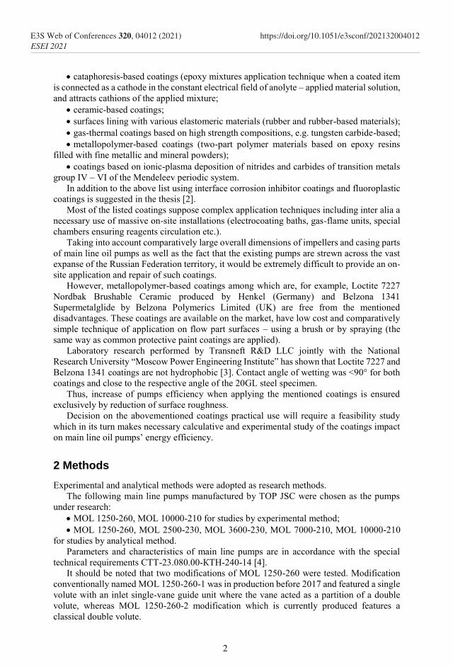
Head and energy characteristics of MOL 1250-260-2 in dimensionless form, before and
after coating application, are given in figure 5.
9
E3S Web of Conferences 320, 04012 (2021)ESEI 2021
https://doi.org/10.1051/e3sconf/202132004012
Fig. 5. Characteristics of MOL 1250-260-2.
Increase in MOL 1250-260 pumps’ head and efficiency at rated capacity (~1250 m3)
equaled to:
for MOL 1250-260-1 – ΔH = 6,7 m; Δη =2 %;
for MOL 1250-260-2 – ΔH = 4,9 m; Δη =2.4 %.
Study of surface coatings of impellers installed in MOL 1250-260 pumps was not
performed because of hindered access to inter-vane channels having a relatively small width
and because of impracticality of coating application on impeller disks due to high quality of
their original surfaces (Ra < 1.6).
Similar experimental research was carried out for MOL 10000-210 pump. As in the case
of MOL 1250-260-2 the spiral ducts of the volute were polished. Tests with coating of
impeller vanes showed unreliability of such coating. During inspection of impellers of two
MOL 10000-210 pumps significant coating chipping was revealed on the vanes’ surfaces
which, apparently, can be explained by a hindered access to inter-vane channels and therefore
impossibility to ensure high quality application of the coating. In this case mechanical
polishing of vanes seems to be useful as well as choosing corrosion-resistant materials for
impellers manufacture.
Test results of MOL 10000-210 pump with polished surfaces of the volute spiral channels
have practically coincided with the results of the initial variant.
Slight increase of efficiency for 0.1…0.2 % had been observed in the area of its maximum
values which cannot be considered as a valid result because the limit error for efficiency
measurement eη = 0.75% on the test bench significantly exceeds the mentioned values.
Difference between the result obtained for MOL 10000-210 and the result obtained for
MOL 1250-260 pumps can be explained by the fact that dimensions of channels’ cross-
sections (hydraulic diameters of channels) in MOL 10000-210 are considerably larger than
those of MOL 1250-260 pumps.
At the same time, the absolute roughness value of flow part cast surfaces on both pumps
is Ra40 because this value is mainly defined by casting techniques. Therefore, relative
roughness value (absolute roughness - hydraulic diameter ratio) of the original flow part
10
E3S Web of Conferences 320, 04012 (2021)ESEI 2021
https://doi.org/10.1051/e3sconf/202132004012

surfaces of MOL 10000-210 are considerably less than that of MOL 1250-260, and reduction
of relative roughness while coating application is not so dramatic.
The accuracy of defining MOL 10000-210 efficiency increase value by means of CFD
analysis is also doubtful because CFD method can have its error exceeding 0.2 %.
In the light of the above the impact of coatings applied on a volute on pumps efficiency
is advisable to study by analytical method which lacks the disadvantages of the experimental
method and CFD method in terms of errors.
3.2 Results of studies via use of an analytical method
With reference to roughness ks = 92 μm (Ra40) and ks = 0 μm efficiency increase values were
obtained for MOL type pumps by comparative calculations using an analytical method
(figure 6).
Fig. 6. Efficiency increases in MOL pumps.
It is notable that for MOL 1250-260-2 coincidence of calculated and experimental values
was 100 %. Such accurate result is most probably accidental because similar calculations
carried out for MOL 1250-260-1 pump where the coating was applied not only on spiral
channels but also on the crossover duct with a conical diffuser showed efficiency increase
for 2.2 % in contrast to experimental value 2.0 % which is, however, also a good result.
As expected, efficiency increase for MOL 10000-210 was a small value of 0.3 % which
is extremely difficult to record adequately by experimental methods.
Values of decrease in MOL pumps consumed power corresponding to the
abovementioned efficiency increase values shall be additionally analyzed.
Fig. 7. Decrease in power consumption by MOL pumps.
11
E3S Web of Conferences 320, 04012 (2021)ESEI 2021
https://doi.org/10.1051/e3sconf/202132004012

As it can be seen from figure 7 the decrease in power consumption for all pumps is a
significant value.
3.3 Estimation of cost advantage of smooth coatings application
Considering the obtained power consumption decreases values it is possible to estimate
annual money savings. For this purpose, we can assume the cost of one kilowatt-hour of
electric energy equal to 4 ruble and the pump annual load factor (pump annual running hours
– number of hours in a year ratio) kR equal 0.5.
Annual average money savings can be defined using formula:
av 8760 Δ ,R ρ eeS k k P C (25)
where Cee – cost of one kilowatt-hour of electric energy, kρ – factor considering the density
of pumped medium (medium density – water density ratio, for oil kρ = 0.86), 8760 – number
of hours in a year.
Considering that 1 kg of LOCTITE 7227 Nordbak Brushable Ceramic costs
approximately 8.3 thousand rubles in the year 2019 and 1 kg of this coating is enough to
apply on 100 % of spiral channels area of MOL 1000-210 volute, it is evident that the annual
cost advantage will practically correspond with the values given in figure 8.
Fig. 8. Average annual savings, thousand rubles.
Trial operation of MOL 1250-260-1 pump with Belzona 134 coating applied started in
2018 at an oil pumping station. At the last pump stripping in October 2019 its running hours
equaled to more than 4000 hours (~0,46 of one year duration) for 1 year and a half. The
coating was in a satisfactory condition, there were no coating chipping or wear found on the
spiral channel surfaces. Thus, it can be stated with high degree of certainty that the
abovementioned cost advantage will be guaranteed at kR = 0.5.
4 Discussion
Significant effect – reduction of power consumption by one pump within the range of values
from 20 to 40 kWt as well as cost advantage from 300 to 600 thousand rubles per year can
be achieved even if Loctite 7227 Nordbak Brushable Ceramic and Belzona 1341
Supermetalglide coatings lack of hydrophobic properties. With this, efficiency increase
values at rated capacity fall within the range from 2.4 % for MOL 1250-260 to 0.3 % for
MOL 10000-210.
However, several researchers, for example [2], note that having hydrophobic properties
can considerably enhance the coating effect. Hence, it follows that coatings manufacturers
12
E3S Web of Conferences 320, 04012 (2021)ESEI 2021
https://doi.org/10.1051/e3sconf/202132004012

should lean toward development of new compositions combining the advantages of both
smooth non-hydrophobic and hydrophobic coatings:
easy application on surfaces;
repairability of coatings;
low cost;
additional decrease in hydraulic losses due to hydrophobic properties.
Considering the quantity of pumps operated in Transneft system (more than 2000 pcs)
potential savings can amount to 600 million rubles and more per year.
Though the cost advantage values are high, there is still an additional potential for its
growth. This potential can be fulfilled provided that the coating will be applied on crossover
channel surfaces of a double volute and on conical diffuser surfaces.
In the design of MOL pumps currently in use the crossover channel surfaces are not
accessible for paint coating and there is no access to the conical diffuser surface for coating
repair in the course of pump operation because MOL pump branches are connected to
pipelines by welding.
Access to the said surfaces can be provided through improvement of pump design, for
example, by equipping pumps with detachable disassemblable flow parts as it is implemented
in the utility model patent RU193781U1 (Single Stage Double Entry Centrifugal Pump).
The mentioned area of work is a promising one and requires research and development
activities.
Agreement of experiment results with the results of efficiency increase calculations
carried out by using the analytical method suggested herein shows the validity of the
approach. The mentioned agreement also confirms feasibility of using formula (23) for
technical roughness value Ra translation into an equivalent sand roughness value kS for cast
surfaces exposed to shot blasting. The suggested analytical procedure can be used for express
analysis of coatings effectiveness at pumps operation in the peak efficiency region as well as
in cases where efficiency increase values are too low and cannot be adequately defined by
using other methods (experiment, CFD calculations).
Pump characteristics behavior after coating application was defined using an
experimental method:
efficiency increase occurs mainly due to increase in pump head;
efficiency increase is bigger when pump operates at capacities exceeding the rated one,
and declines at capacities lower than the rated one;
coating application results in shift of capacity value corresponding with peak efficiency
to the side with higher values (to the right of the characteristic curve).
It should be additionally noted that validation of CFD methods and the respective
software from the point of view of its use for coatings effectiveness evaluation is a promising
field of work.
5 Conclusion
Experimental study of smooth coatings impact on the efficiency of main line oil pumps have
been carried out.
Practical evaluation of an analytical procedure for coatings effectiveness assessment have
been performed; based on the results of the evaluation a conclusion about the validity of the
said procedure was made.
Based on the results of performed studies the feasibility of using smooth coatings of
Loctite 7227 Nordbak Brushable Ceramic and Belzona 1341 Supermetalglide type for
application on volute flow parts in all types of MOL pumps was validated.
13
E3S Web of Conferences 320, 04012 (2021)ESEI 2021
https://doi.org/10.1051/e3sconf/202132004012

Estimation of cost advantage have been carried out which amounted from 300 to 600
million rubles per year for one pump depending on its type and size.
References
1. P. A. Revel-Muroz, Development of methods for improvement of oil transportation
energy efficiency with introduction of a complex of energy saving technologies. Thesis
in support of candidature for a technical degree (Ufa) pp 11-12, 2018
2. S. A. Chernyshev, Improvement of centrifugal pumps performance through change of
work flow hydrodynamic interaction with flow part elements. Thesis in support of
candidature for a technical degree (Moscow) pp 38-44, 2008
3. V. I. Voronov, Kazantsev M. N., Flegentov I. A., Starshinov D. M., Ivanov A. G.
Testing of hydrophobic coatings applied on pumps’ flow parts aimed at improvement
of main line oil pumps efficiency. Summary scientific and technical report (Moscow:
Transneft R&D, LLC) p 43
4. Oil and Oil Products Main Pipeline Transportation. Advanced Main Line and Booster
Pumps. Special Technical Requirements. СТТ-23.080.00-КТН-240-14 (with
Amendment 1). (Moscow: Transneft R&D, LLC) pp 17-18
5. S. V. Akimov and Shoter P. I. A new approach for calculating hydraulic losses in
centrifugal pump’s volute J. Pumps. Turbines. Systems 26 56-65, 2018
6. J. F. Gülich, Centrifugal pumps (Villeneuve, Switzerland: Springer International
Publishing), 2020
14
E3S Web of Conferences 320, 04012 (2021)ESEI 2021
https://doi.org/10.1051/e3sconf/202132004012