Embed Size (px)
Citation preview

Civil and Environmental Research www.iiste.org
ISSN 2224-5790 (Paper) ISSN 2225-0514 (Online) DOI: 10.7176/CER
Vol.11, No.3, 2019
1
Experimental and Finite Element Analysis of Continuous RC Slab
Panels with Steel Fiber Reinforced Concrete (SFRC) as an
Alternative to Negative Reinforcement
Ali Hameed Aziz1* Wisam K. Al-Saraj2 Mithaq A. Louis2
1.Professor -College of Engineering-Al-Mustansiriayah University- Baghdad-Iraq
2.Assist. Prof. -College of Engineering-Al-Mustansiriayah University- Baghdad-Iraq
Abstract
This paper presents experimental and finite element analysis of RC slab panels with steel fiber reinforced concrete
(SFRC). For this purpose, four SFRC slab panels with (2000×250×50mm) dimensions are poured using a concrete
class of (f'c=22MPa) with (15kg/m3) dosage of steel fibers and steel class (fy=410MPa) without shear stirrups. Two
of the slab panels were modeled by using nonlinear material properties adopted from experimental study and
analyzed till the ultimate failure by ANSYS (Version-15) software. The tested slab panels are subjected to bending
by two-point loading, exactly after having been moist-cured for (28 days). The slab panels were tested up to the
failure with control of loads. The applied loads and mid-span deflections are carefully recorded at every (5kN)
load increment from the beginning till the ultimate failure. The results obtained from the finite element and
experimental analyses are compared to each other. It is seen from the results that the finite element failure behavior
indicates a good agreement with the experimental failure behavior. The paper concludes that the traditional
negative steel reinforcement (steel bars) can be replaced (partially or totally) by using the adopted technique and
the contribution of SFRC in manufacturing of thin slabs panels was enhanced.
Keywords: Finite Element, Steel fiber, Continuous Slab, Concrete, NSC, Ansys.
DOI: 10.7176/CER/11-3-01
Publication date: April 30th 2019
1. Introduction
Slab panels can be used as floor or roof simply supported on masonry components or load bearing walls, steel or
concrete beams. This technique of construction is widely used and suitable for residential, commercial,
prefabrication, industrial buildings. A thin slab is widely used in shell structures such as hangers, exhibition halls,
industrial buildings and a variety of other large span structures. For bridges, deck panels may be poured away from
the site at a pre-casting plant and shipped to the site once they have cured and are ready for placement (Erection).
This feature helps to minimize disruptions to traffic, improve construction quality, and lower overall construction
time. Once at the site the slab panels may be placed directly on precast girders and connected through different
methods between adjacent slab panels and connections between panels and supporting elements (girders).
Generally, this type of slabs reinforced in longitudinal direction by two layers (top and bottom) to resist positive
and negative bending moments produced due to applied loads.
It is an established fact the flexural resistance of the SFRC slab-system did not change even if the conventional
reinforcement in the slab section was totally or partially dispensed with and it was replaced with a suitably dose
of the steel fibers in the concrete mix. Steel fiber-added reinforced concrete (SFRC) applications have become
widespread in areas such as tunnel shells, concrete sewer pipes, and slabs of large industrial buildings. The
inclusion of the steel fibers in the concrete at the time of its production leads to a significant improvement of
strength properties of the concrete, especially the residual-tensile strength and the toughness (energy absorption)
(Sethunarayanan R., 1960; Raouf et al., 1984). Several experimental investigations were conducted to increase
the flexural or shear strength of slabs or beams by using steel fiber reinforced concrete (Noghabai, K., 2000; Shah,
R., 2004; Gustafsson et al., 2005; Ali H., 2006; Husain et al. 2006; Ali et al., 2013) or high strength concrete or
concrete polymer composite (Al-Karkhy H., 2004).
2. Paper Significant
The using of SFRC to produce slab panels is more effective because of the smaller slab thickness, in comparison
to the beams, that acquires a preferential fiber orientation along its length and breadth, and consequentially leads
to a favorable alignment of the steel fibers along the principle directions of the moment trajectories.
3. Experimental Work
The experimental work was carried out on four rectangular section slab panels, continuous (rest on three supports)
under monotonic concentrated load (in the center of each span). One of which were made fully with NSC, and the
others were made partially with SFRC in negative moment zone. All slab panels were reinforced with tension bars
at mid spans (positive reinforcement at bottom), while, for reference slab panel, tension bars (top reinforcement)

Civil and Environmental Research www.iiste.org
ISSN 2224-5790 (Paper) ISSN 2225-0514 (Online) DOI: 10.7176/CER
Vol.11, No.3, 2019
2
were used at meddle support (negative reinforcement at top) and extended to adjacent span distance equals to one
third of adjacent spans, ACI-318M08 Code. It may be noted that the tested panels were made without shear
reinforcement.
Two variables were adopted in this study, presence or absence of SFRC and steel fibers type (straight, hocked-
end and crimped) of steel fiber reinforced concrete. The span, cross-section, concrete strength, steel fiber volume
friction, and positive reinforcement (bottom reinforcement) were kept constant without any changed for all tested
specimens. Furthermore, a series of tests were performed on concrete mixes to evaluate the mechanical properties
of hardened concrete. All slab panels were made with (2000x250x50mm) dimensions for length, width and
thickness respectively. Figures (1) and (2) present the detailed testing program and nominal dimensions of the
tested slab panels.
The main reinforcement consisted of (2ϕ10mm) mild, hot-rolled, deformed steel bars employed as tension
reinforcement (flexural reinforcement). The longitudinal tension reinforcement was bent with (90О) angle at the
ends to prevent any steel-concrete bond slip. The reinforcement bars were placed inside the mold with (10mm)
concrete cover. The tested slab panels are designated as shown in Table (1).
Table 1. Description of Test Slab Panels
Slab Designation Reinforcement
Positive (bottom)b Negative (top)c
SP-1a
2ϕ10
2ϕ10mm Steel Bars
SP-2 SFRC (Hocked-end Fiber)
SP-3 SFRC (Straight Fiber)
SP-4 SFRC (Crimped Fiber) a Reference Slab (Full Slab made with NSC) b At mid spans (positive reinforcement at bottom). c At medium support (negative reinforcement).
Figure 1. Slab Panel Dimensions and Details (Isometric View)
Figure 2. Slab Panel Concrete Poured Process
3.1 Materials
In manufacturing the test slab specimens, the properties and description of materials used are reported and
presented in Tables (2) and (3), and the mix proportions for the normal strength concrete (NSC) and steel fiber
reinforced concrete (SFRC) are presented in Table (4).
2000mm
50mm
250mm
NSC
NSC SFRC
SFR
C
NSC
NSC
SFRC
Top Reinforcement

Civil and Environmental Research www.iiste.org
ISSN 2224-5790 (Paper) ISSN 2225-0514 (Online) DOI: 10.7176/CER
Vol.11, No.3, 2019
3
Table 2. Properties and Description of Materials
Material Descriptions
Cement Ordinary Portland Cement (Type I).
Sand Natural sand with maximum size of (4.75mm).
Gravel Crushed gravel with maximum size of (12mm).
Reinforcing Bars (ϕ10 mm) deformed steel bars having yield strength fy= 410 MPa.
Water Clean tap water.
Table 3. Properties and Description of Steel Fibers
Steel Fiber Type Properties a
Hocked-end Mild carbon steel fibers with average length of (50mm), nominal diameter of
(0.5mm), aspect ratio of (100) and yield strength of (1130MPa).
Straight Smooth mild carbon steel fibers with average length of (25mm), nominal
diameter of (0.5mm), aspect ratio of (50) and yield strength of (1650MPa).
Crimped Mild carbon steel fibers with average length of (25mm), nominal diameter of
(0.5mm), aspect ratio of (50) and yield strength of (1130MPa).
aFrom Manufacturers (N. V. Bekaert Corporation for steel wire fibers, Belgium).
Table 4. Proportions of Concrete Mixes
Parameter Concrete Type
NSC SFRC
Water/cement ratio 0.5 0.5
Water (kg/m3) 180 180
Cement (kg/m3) 350 350
Fine Aggregate (kg/m3) 800 800
Coarse Aggregate (kg/m3) 1000 1000
Steel Fiber volume (%) - 1.0
3.2 Test Measurements and Instrumentation
Hydraulic universal testing machine (300ton Capacity) is used to test the slab specimens as well as control
specimens. Central deflection has been measured by means of (0.01mm) accuracy dial gauge (ELE type) and
(30mm) capacity. The dial gauges were placed underneath the bottom face of each span at mid.
3.3 Test Results of Control Specimens
Test results of mechanical properties of specimens are summarized and presented in Table (5). Compressive
strength for cylinders was carried out on NSC and SFRC in accordance with ASTM-C39-96, while, the tensile
strength (Split cylinder) test were carried out in accordance with ASTM-C496-75.
Table 5. Mechanical Properties of Concrete
Property
(MPa)
Concrete Type
NSC SFRC
Hocked-End Straight Crimped
(f'c) 22 24 22.5 24
( fct) 4.7 7.5 6.2 7.25
3.4. Test Procedure
All slab specimens were tested, at ages of (28) days, using universal testing machine with monotonic loading to
ultimate states as shown in Figure (3).

Civil and Environmental Research www.iiste.org
ISSN 2224-5790 (Paper) ISSN 2225-0514 (Online) DOI: 10.7176/CER
Vol.11, No.3, 2019
4
Figure 3. Set up of Slab Panel Specimens
The tested slabs were simply supported over effective spans of (950mm) and loaded with a single-point load
at mid of effective spans. The slab specimens were placed on the testing machine and adjusted so that the
centerline, supports, point loads and dial gauges were in their correct or best locations. Loading was applied slowly
in successive increments, at the end of each load increment, observations and measurements were recorded for the
mid-span deflections and crack development and propagation on the slab surface. When the samples reached
advanced stage of loading, smaller increments were applied until failure, where the load indicator stopped
recording for any more and the deflections increased very fast without any increase in applied load. The
developments of cracks (crack pattern) were marked with a pencil at each load increment.
4. Finite Element Analysis
To study the performance of tested slab panels, ANSYS (Version-15) finite element software is used to analyze
two selected, (SP-1) and (SP-2). A nonlinear, eight nodes brick element, (SOLID-65), with three translations DOF
at each node is used to model the concrete. For FEM modeling of the steel reinforcement, two nodes, discrete axial
element, (LINK-180), with three translations DOF at each node is used. To avoid stress concentration, (10mm)
thick steel plate is added at the load locations and modeled by using a nonlinear, eight nodes brick element,
(SOLID-45), with three translations DOF (per node) in x, y and z-directions.
4.1. Properties of Materials
4.1.1. Concretes
For finite element modeling, concrete constitutive stress-strain curve in compression can be described by
isotropically, multi-linear stress-strain relationship. Constitutive model (surface of failure) in ANSYS can be
specifying only by two constants (tensile strength (ft) and compressive strength of concrete (f'c) as given by
criterion of Willam, K., and Warnke, E. . In this paper, transfer coefficients of shear for opened cracks (�o) and
closed cracks (�c) are assumed to be (0.2) and (0.25) respectively. These values are selected to avoid convergence
problems during iteration. The stress-strain curve for concrete in tension is assumed to be linear-elastic up to the
maximum tensile strength. Smeared crack approach is used to model the concrete cracking. Poisson’s ratio, for
finite element modeling of concrete is assumed to be (0.2). In order to modeling the finite element of concrete, the
adopted mechanical properties is reported and listed in Table (6).
Table 6. Mechanical Properties of the Adopted Materials in FEA
Concrete
Type
f'c a
(MPa)
ft b
(MPa)
Ec
(MPa) Note
NSC 22 4.7 22045b Ec =
SFRC 24 7.5 23825c ESFRC= Ef Vf +(1-Vf)Em aExperimental Work b ACI-318M08 Code c Rule of Mixture
4.1.2. Steel Plates and Reinforcement
Young’s modulus of (Es=200GPa) and Poisson’s ratio of (�=0.3) are utilized in FEM for steel plates and
reinforcement. While, yield stress for the steel plates and reinforcement used in FEM follow the design material
properties used for the experimental investigation. The steel reinforcement for the finite element models is assumed
to be elastic-perfectly plastic material and identical in tension and compression. Von-Mises failure criterion is
adopted for modeling. The steel plate under the applied load is assumed to be behaves as linearly-elastic materials.
4.2. Finite Element Modeling and Meshing
The dimensions of the slab panel specimens are shown in Figure (1). Due to simple geometry of the tested
specimens, entire (full) slab panel is used for modeling, Figure (4). The origin point of coordinates lie in one
corners and only one loading plate per span are provided at the top of slab panel (under load) to prevent load
'4700 cf
Left
Support
Mid Support Right Support

Civil and Environmental Research www.iiste.org
ISSN 2224-5790 (Paper) ISSN 2225-0514 (Online) DOI: 10.7176/CER
Vol.11, No.3, 2019
5
concentration. In the beginning, the slab panel and steel plates are modeled as lines, then areas, and finally as
volumes (solid elements). After creating of volumes, meshing of the finite element model is needed. In this stage,
the FEM model is divided into a number of small elements. When the model problem is solving, the stresses and
deformations (strains) are estimated at the Gaussian points of these small elements. Best results can be achieved
by dived (meshing) the model into square (or rectangular) elements. Before distribution (spreading) of the applied
load by using steel plates (in the early attempt), and due to load concentration on concrete elements, concrete
crushing started to create in elements which located directly under load. Thereafter, the concrete elements adjacent
to the applied load were crushed within few steps of loading. Finally, large displacement (deflection) take place,
the solution in not converges and as a result the FEM model failed prematurely. To prevent this FEM failure
phenomenon, steel plates are used and inserted under the applied load.
Figure 4. Modeling and Meshing of the Slab Specimens
4.3. Load Application and Boundary Conditions
To ensure that modeled slab panels behave as an experimental work, boundary conditions (displacement constrains)
at supports should be satisfied (need to be applied at the supports locations). Thereafter, one of the supports is
modeled as a hinge and the others two supports were modeled as a roller. Since the external load was applied on
a steel plate and as a basic of FEM, the plate load must be transformed to adjacent nodes; therefore the applied
load is represented by an equivalent nodal force on the top nodes of plate. The applied load is divided into load
steps and done incrementally up to failure (based on Newton-Raphson technique). At a certain stages in the
analysis, load step size is varied from large (at points of linearity in the response) to small (when cracking and
steel yielding occurred). The failure is assumed to be occurred when the solution, for a minimum load is diverging
and the models have a large deflection (rigid body motion).
Figure 5. Loading and Boundary Conditions
5. Results and discussion
5.1. Experimental work
During the experimental work, cracked and ultimate loads, load versus deflection at mid-span were recorded.
Photographs for the tested specimens are taken to show the crack pattern and some other details. The recorded
data, general behavior and test observations are reported as well as recognizing the effects of various parameters
on the flexural behavior.
5.1.1. General Behavior
Photographs of the tested slab specimens are shown in Figure (6) and test results are given in Table (7). All
specimens were designed to fail in flexure with tensile mode, which was characterized by the formation of cracks
in the tensile stress zones, then yielding of steel bars and shifting the neutral axis upwards. At early stages of
loading, several cracks initiated in the tension zones at the maximum moment regions. With further loading, these
cracks extended and became wider. At about (60%) of the ultimate load, more cracks developed at the bottom of

Civil and Environmental Research www.iiste.org
ISSN 2224-5790 (Paper) ISSN 2225-0514 (Online) DOI: 10.7176/CER
Vol.11, No.3, 2019
6
the slab and proceeded towards the main cracks and often joined together. As expected, the main cracks for all
tested specimens commenced at the middle zone and all slab specimens exhibited ductile flexural failure.
Table 7. Mode of Failure, Ultimate and Cracking Loads
Slab
Designation
Load (kN)
Ru
u
)P(
P a
Rcr
cr
)P(
P a Mode of
Failure Pu Pcr
SP-1 31 8 1.0 1.0 Tensile Failure
SP-2 43 10 1.39 1.25 =
SP-3 38 10 1.23 1.25 =
SP-4 49 13 1.58 1.625 =
a (Pu)R and (Pcr)R are Reference Beam Ultimate and Cracking Loads.
Figure 6. Crack Patterns for Tested Specimens (Bottom Face)
5.1.2. Ultimate Strength (Pu)
The recorded ultimate loads of the tested specimens are presented in Table (7). For tested specimens (SP-2, SP-3
and SP-4), which had SFRC instead of tension reinforcement in negative moment at medium support, the increase
in strength were (39%, 23% and 58%). This enhancement is due to the high aspect ratio, fiber length and adequate
volume fraction of the used fibers. The randomly oriented steel fibers have the ability to arrest cracking and restrain
propagation and these caused an increase in the load carrying capacity beyond the first cracking. Generally, it can
be seen that the tested specimens strengthened with SFRC exhibit larger ultimate strength than reference specimens
which fully made with NSC. With increasing the steel fiber volume fraction, the traditional negative steel
reinforcement (steel bars) can be replaced (partially or totally) by using SFRC in manufacturing of thin slabs
panels.
5.1.3. First Cracking Loading (Pcr)
The first cracking loadings are presented in Table (7), and crack patterns for tested specimens are shown in
photograph of Figure (6). For all tested specimens, comparison will be made with first cracking load for the
reference beams (Pcr)R. For slab specimen containing SFRC, (SP-2, SP-3 and SP-4), the addition of steel fibers
increased the cracking load that induces first crack by (25%, 25% and 62.5%) comparing with the average first
cracking load of reference slab (SP-1). This is due to the ability of steel fibers in arresting crack growth and
restraining cracking widening. As expected, slab specimens made with SFRC exhibit larger cracking loads
comparing with the reference one.
5.1.4. Load-Deflection Behavior
Load-deflection curves of the tested slabs at mid-span at all stages of loading up to failure are constructed and
presented in Figure (7). At the beginning, all curves were identical and the tested specimen exhibited linear
behavior and the initial change of slope of the load-deflection curves occurred at (10kN), which indicated the first
crack loads. Beyond the first crack loading, the slabs behaved in a certain manner.
Figure 7. Mid-Span Load-Deflection Curves (Left and Right Spans)
0
10
20
30
40
50
60
0 5 10 15 20
Load
(k
N)
Deflection (mm)
SP-1SP-2SP-3SP-4
0
10
20
30
40
50
60
0 5 10 15 20
Load
(k
N)
Deflection (mm)
SP-1SP-2SP-3SP-4
Civil and Environmental Research www.iiste.org
ISSN 2224-5790 (Paper) ISSN 2225-0514 (Online) DOI: 10.7176/CER
Vol.11, No.3, 2019
7
Generally, the load- deflection behavior (for left and right spans) is approximately same, which indicated that
the spans behave in same manner. The increase of the ultimate load of slab (SP-2) was observed in comparing
with (SP-1). This enhancement is due to presence of SFRC and the ability of steel fiber to arrest cracking and
restrain propagation and these caused an increase in both, ductility and the load carrying capacity beyond the first
cracking. Load-deflection curve for slab (SP-3) exhibits smooth increase in both applied loads and deflections.
Presence of SFRC in caused an increase in the load carrying capacity beyond the first cracking and this was
reflected on the corresponding deflections. Behavior of slab (SP-4) exhibited greater loads and deflections in
comparison with the other slabs. This panel had the greatest stiffness due to presence of high efficient fiber
(crimped fibers) in SFRC.
5.1.5. Steel Fiber Type Effect
As shown in Table (7), when the SFRC which content hocked end fibers are use, the ultimate strength and cracking
load increased (39%) and (25%) respectively. When the steel fiber changed to straight type, the ultimate strength
and cracking load increased (23%) and (25%) respectively. While, when the crimped type employed, the ultimate
strength and cracking load increased (58%) and (62.5%) respectively. This may be due to geometrical shape of
crimped fiber which makes it extended through large surface area.
5.2. Finite Element Analysis
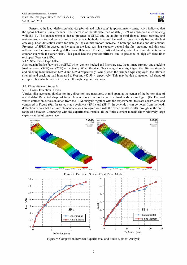
5.2.1. Load-Deflection Curves
Vertical displacements (Deflection in y-direction) are measured, at mid-span, at the center of the bottom face of
tested slabs. Deflected shape of finite element model due to the vertical load is shown in Figure (8). The load
versus deflection curves obtained from the FEM analysis together with the experimental tests are constructed and
compared in Figure (9)., for tested slab specimens (SP-1) and (SP-4). In general, it can be noted from the load-
deflection curves that the finite element analyses are agree well with the experimental results throughout the entire
range of behavior. Comparing with the experimental results, all the finite element models show relatively large
capacity at the ultimate stage.
Figure 8. Deflected Shape of Slab Panel Model
Figure 9. Comparison between Experimental and Finite Element Analysis
0
5
10
15
20
25
30
35
0 5 10 15
Load
(k
N)
Deflection (mm)
Experimental
Finite Element
0
10
20
30
40
50
60
0 5 10 15 20 25
Load
(k
N)
Deflection (mm)
Experimental
Finite Element
SP-1 SP-4

Civil and Environmental Research www.iiste.org
ISSN 2224-5790 (Paper) ISSN 2225-0514 (Online) DOI: 10.7176/CER
Vol.11, No.3, 2019
8
5.2.2. Ultimate Loads
Table (8) shows the comparison between the ultimate loads of the experimental (tested) beams, (Pu)EXP., and the
final loads from the finite element models, (Pu)FEM. The final loads for the finite element models are the last
applied load steps before the solution starts to diverge due to numerous cracks and large deflections. As shown in
Table (8), the ultimate loads obtained from numerical model agree well with the corresponding values of the
experimental (tested) slab panels.
Table 8. Ultimate Loads of the Experimental Tests and Finite Element Models
Slab Model Ultimate Load (kN)
.EXPu
FEMu
)P(
)P( Mode of
Failure (Pu)EXP (Pu)FEM
SP-1 31 33 1.06 Tensile Failure
SP-4 49 55 1.12 =
5.2.3. Crack Patterns
The crack pattern is recorded, after first crack, at each load step. Cracks pattern come by the FEM analysis and the
failure modes of the tested slabs are agree well, as shown in Figure (10). Cracks pattern appearances reflect the
failure mode of tested specimens. The model of FEM, accurately, predicts that the tested slabs are failing in
bending and predicts that the vertical and cracks formed in the mid span regions. The cracks are concentrated
under load region and mid support.
Figure 10. Cracks pattern From FEM analysis
5. Conclusions
For the tested slab panel specimen which contains SFRC instead of traditional negative steel reinforcement (steel
bars), the increases in ultimate strength were (23% - 58%). Addition of steel fibers increased the cracking load by
about (25%- 62.5%). Employ the crimped steel fibers, led to increase the ultimate strength and cracking load
greater than the other types. This may be due to geometrical shape of crimped fiber which makes it extended
through large surface area. The results obtained from the finite element and experimental analyses are compared
to each other. It is seen from the results that the finite element failure behavior indicates a good agreement with
the experimental failure behavior. The paper concludes that the traditional negative steel reinforcement (steel bars)
can be replaced (partially or totally) by using the adopted technique and the contribution of SFRC in manufacturing
of thin slabs panels was enhanced.
References
Sethunarayanan, R. (1960). Ultimate Strength of Pre-tensioned I-beams in Combined Bending and Shear.
Magazine of Concrete Research, 12, 83-90.
Raouf, Z. A. & Hussain, A. A. (1984). Technical notes: Some Properties of Steel Fibre Concrete at Early Ages.
International Journal of Cement Composites and Lightweight Concrete, 6, 117-121.
Noghabai, K. (2000). Beams of Fibrous Concrete in Shear and Bending: Experimental and Model. ASCE-Journal
of Structural Engineering, 126, 243-251.
Shah, R. H., & Mishra, S. V. (2004). Crack and Deformation Characteristics of SFRC Deep Beams. Journal of
Indian Engineering, 85, 44-48.
Gustafsson, J., & Noghabai, K. (2005). Steel Fibers as Shear Reinforcement in High Strength Concrete Beams.
[Online] Available: https://www.danskbetonforening.dk/media/ncr/publication-no-22-03.pdf
Ali H. (2006) .Flexural and Shear Behavior of Hybrid I-Beams with High-Strength Concrete and Steel Fibers. Ph.
D. Thesis, Department of Civil Engineering, Al-Mustansiryah University, Iraq.
Husain M. Husain, Bayan S. Al-Nu’man & Ali H. (2006) .Shear Behavior of Hybrid Reinforced Concrete I-Beams
Containing Steel Fiber Reinforced Concrete (SFRC) and High Strength Concrete (HSC). Journal of

Civil and Environmental Research www.iiste.org
ISSN 2224-5790 (Paper) ISSN 2225-0514 (Online) DOI: 10.7176/CER
Vol.11, No.3, 2019
9
Engineering and Development, 10, 36-52.
Ali H., Mithaq A. Louis & Wissam K. Al-Saraj, (2013). Using Steel Fiber Reinforced Concrete (SFRC) as an
Alternative to Negative Reinforcement in Continuous RC Slab Panels. Iraqi Journal of Civil Engineering, 9,
17-26.
Al-Karkhy, H. (2004). Punching Shear Strength of Polymer and Fiber Reinforced Polymer Concrete Slabs. MSc
thesis, Civil Engineering Department, College of Engineering, Al-Mustansiriyah University, Baghdad- Iraq.
ACI Committee 318, (2008) .Building Code Requirements for Structural Concrete (ACI 318-08) and Commentary
(ACI 318R-08). American Concrete Institute, Farmington Hills, MI, USA.
ASTM C39-96, (1996). Test Method for Compressive Strength of Cylindrical Concrete Specimens. American
Society for Testing and Materials, USA.
ASTM C78-75, (1975). Standard Test Method for Flexural Strength of Concrete (Using Simple Beam with Third-
Point Loading). American Society for Testing and Materials, USA.
Willam, K., & Warnke, E. (1975). Constitutive Model for the Triaxial Behavior of Concrete. Proceedings,
International Association for Bridge and Structural Engineering, 19,174.


![INVESTIGATING THE NON-LINEAR BEHAVIOR OF RC FRAMED ...€¦ · K braced frame. [5] Investigated the behavior of RC beam-column connection using finite element analysis. Separate finite](https://img.pdfslide.net/doc/110x75/605faa960f9bec1b2d32278a/investigating-the-non-linear-behavior-of-rc-framed-k-braced-frame-5-investigated.jpg)