Embed Size (px)
Citation preview

HAL Id: hal-01620291https://hal.archives-ouvertes.fr/hal-01620291
Submitted on 15 Feb 2019
HAL is a multi-disciplinary open accessarchive for the deposit and dissemination of sci-entific research documents, whether they are pub-lished or not. The documents may come fromteaching and research institutions in France orabroad, or from public or private research centers.
L’archive ouverte pluridisciplinaire HAL, estdestinée au dépôt et à la diffusion de documentsscientifiques de niveau recherche, publiés ou non,émanant des établissements d’enseignement et derecherche français ou étrangers, des laboratoirespublics ou privés.
Experimental and numerical analysis on drilling ofcarbon fibre reinforced plastic and aluminium stacksRedouane Zitoune, V. Krishnaraj, Francis Collombet, Sabine Le Roux
To cite this version:Redouane Zitoune, V. Krishnaraj, Francis Collombet, Sabine Le Roux. Experimental and numericalanalysis on drilling of carbon fibre reinforced plastic and aluminium stacks. Composite Structures,Elsevier, 2016, 146, pp.148-158. �10.1016/j.compstruct.2016.02.084�. �hal-01620291�

Experimental�and�numerical�analysis�on�drilling�of�carbon�fibre�reinforced�plastic�and�aluminium�stacksR.�Zitoune�a,⇑,�V.�Krishnaraj�b,�F.�Collombet�a,�S.�Le�Roux�c
a Institut Clément Ader (ICA), IUT-A of Toulouse Université, 133c, avenue de Rangueil, 31077 Toulouse cedex, FrancebDepartment of Production Engineering, PSG College of Technology, Coimbatore 641004, IndiacUniversité de Toulouse; CNRS, Mines Albi, INSA, UPS, ISAE-SUPAERO; ICA (Institut Clément Ader); Campus Jarlard, F-81013 Albi, France
Keywords:MachiningFinite element analysis (FEA)CFRP/Al stacks
a b s t r a c t
In this paper, experimental and numerical study of drilling of carbon fibre reinforced plastic (CFRP) lam-inate with aluminium alloy stacks has been carried out. Drilling of these multi-materials is a challengingtask to manufacturing engineers because of different mechanical properties of materials. In this work, theimpact of the machining parameters on the effect of twist drill and the geometry of double cone drill oncutting forces, holes quality and on CFRP/Al interface have been investigated. From the experimentalstudy, it was found that the double cone drills induce less thrust force compared to the standard twistdrill. From the numerical analysis based on the linear fracture mechanics of the CFRP and the plasticbehaviour of the aluminium with isotropic hardening, on the one hand, the critical thrust force respon-sible for the delamination of the last ply as a function of the aluminium thickness has been identified andon the other hand, the maximum thrust force responsible for the interface separation of CFRP/Al has beenpredicted as a function of the aluminium thickness.
1. Introduction
Drilling and fastening of the CFRP & metals in one-shot opera-tion reduce manufacturing time in building aircraft structures.The most common problems encountered during automatic dril-ling of CFRP/metal structures (composite/titanium or composite/aluminium) are (i) the damage on the composite material due tothe interaction between the continuous metallic chips and the sur-face of the composite material, (ii) the high thrust force inducedduring drilling can separate CFRP and aluminium plates which con-tribute to the accumulation of aluminium chip and carbon dust atthe interface of CFRP/Al, and finally (iii) the adhesion of the metal-lic layer on the cutting edge of the tool. LATECIS, a French companyin Toulouse, has developed a system called OPERA, which is dedi-cated for one shot drilling. Ideally the OPERA system is expected tohandle high production rates (1 attachment mounted approxi-mately at every 12 s) [1–3]. The automation of these tasks mustalso enable greater mounting precision, improved ergonomics,health and safety of the operators, particularly for the new hybridmaterials like composite/titanium or composite/aluminium assem-blies. Due to the different mechanical properties of materials
constituting the hybrid panels, their machinability remains anopen problem and can prevent the automation of these tasks.
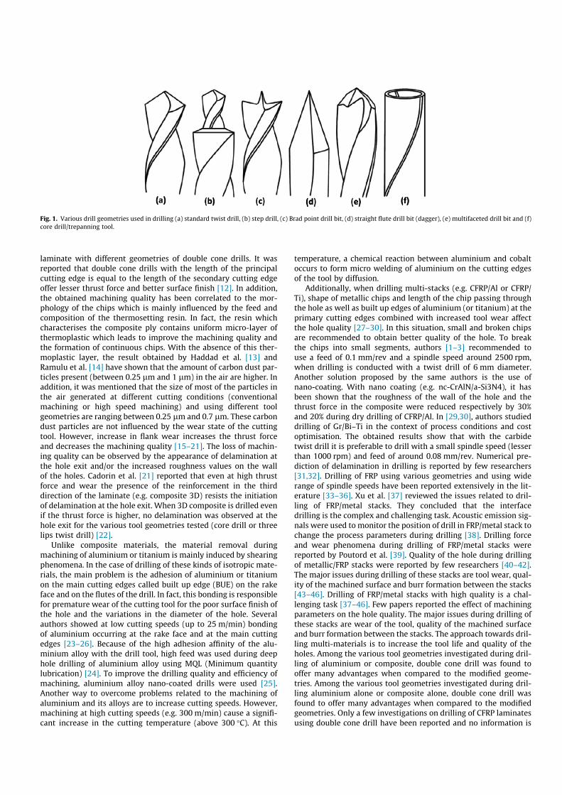
From the literature, it is found that the composite materials,especially CFRP’s are often used to a larger extent due to theirdownsizing and rightsizing impacts. However, due to their lami-nated structure and the anisotropy of the carbon fibre reinforcedplastics several damage modes are seen during drilling. Thesedamage types are peel up delamination at the hole entry, thermalalteration, fibre pull-out and fuzzing on the wall of the hole, andexit delamination and uncut fibre at the hole exit [4–6]. Moreover,the mechanism of material removal in composite materials isstrongly influenced by the relative angle between the direction ofthe cutting speed and the direction of orientation of fibre [7,8].Sakuma et al. [9] drilled holes by using four drill bit materialsand investigated drill wear pattern, flank wear width and cuttingforces. Few researchers investigated the effect of tool geometrieson drilling of polymer composite materials. Many of the modifiedgeometries (Zhirov point, Brad and Spur, step drill, candle stick,saw drill, etc. (Ref. Fig. 1)) are difficult to regrind [10–12]. Krish-naraj et al. [10] drilled composites at high spindle speed and stud-ied the influence of tool geometries. They reported that doublecone drill offers better surface finish when compared to standardtwist drill and Brad & Spur drill. This result is in good agreementwith the work of Zitoune et al. [12] while drilling of carbon/epoxy⇑ Corresponding author.
E-mail address: [email protected] (R. Zitoune).
laminate with different geometries of double cone drills. It wasreported that double cone drills with the length of the principalcutting edge is equal to the length of the secondary cutting edgeoffer lesser thrust force and better surface finish [12]. In addition,the obtained machining quality has been correlated to the mor-phology of the chips which is mainly influenced by the feed andcomposition of the thermosetting resin. In fact, the resin whichcharacterises the composite ply contains uniform micro-layer ofthermoplastic which leads to improve the machining quality andthe formation of continuous chips. With the absence of this ther-moplastic layer, the result obtained by Haddad et al. [13] andRamulu et al. [14] have shown that the amount of carbon dust par-ticles present (between 0.25 lm and 1 lm) in the air are higher. Inaddition, it was mentioned that the size of most of the particles inthe air generated at different cutting conditions (conventionalmachining or high speed machining) and using different toolgeometries are ranging between 0.25 lm and 0.7 lm. These carbondust particles are not influenced by the wear state of the cuttingtool. However, increase in flank wear increases the thrust forceand decreases the machining quality [15–21]. The loss of machin-ing quality can be observed by the appearance of delamination atthe hole exit and/or the increased roughness values on the wallof the holes. Cadorin et al. [21] reported that even at high thrustforce and wear the presence of the reinforcement in the thirddirection of the laminate (e.g. composite 3D) resists the initiationof delamination at the hole exit. When 3D composite is drilled evenif the thrust force is higher, no delamination was observed at thehole exit for the various tool geometries tested (core drill or threelips twist drill) [22].
Unlike composite materials, the material removal duringmachining of aluminium or titanium is mainly induced by shearingphenomena. In the case of drilling of these kinds of isotropic mate-rials, the main problem is the adhesion of aluminium or titaniumon the main cutting edges called built up edge (BUE) on the rakeface and on the flutes of the drill. In fact, this bonding is responsiblefor premature wear of the cutting tool for the poor surface finish ofthe hole and the variations in the diameter of the hole. Severalauthors showed at low cutting speeds (up to 25 m/min) bondingof aluminium occurring at the rake face and at the main cuttingedges [23–26]. Because of the high adhesion affinity of the alu-minium alloy with the drill tool, high feed was used during deephole drilling of aluminium alloy using MQL (Minimum quantitylubrication) [24]. To improve the drilling quality and efficiency ofmachining, aluminium alloy nano-coated drills were used [25].Another way to overcome problems related to the machining ofaluminium and its alloys are to increase cutting speeds. However,machining at high cutting speeds (e.g. 300 m/min) cause a signifi-cant increase in the cutting temperature (above 300 !C). At this
temperature, a chemical reaction between aluminium and cobaltoccurs to form micro welding of aluminium on the cutting edgesof the tool by diffusion.
Additionally, when drilling multi-stacks (e.g. CFRP/Al or CFRP/Ti), shape of metallic chips and length of the chip passing throughthe hole as well as built up edges of aluminium (or titanium) at theprimary cutting edges combined with increased tool wear affectthe hole quality [27–30]. In this situation, small and broken chipsare recommended to obtain better quality of the hole. To breakthe chips into small segments, authors [1–3] recommended touse a feed of 0.1 mm/rev and a spindle speed around 2500 rpm,when drilling is conducted with a twist drill of 6 mm diameter.Another solution proposed by the same authors is the use ofnano-coating. With nano coating (e.g. nc-CrAlN/a-Si3N4), it hasbeen shown that the roughness of the wall of the hole and thethrust force in the composite were reduced respectively by 30%and 20% during dry drilling of CFRP/Al. In [29,30], authors studieddrilling of Gr/Bi–Ti in the context of process conditions and costoptimisation. The obtained results show that with the carbidetwist drill it is preferable to drill with a small spindle speed (lesserthan 1000 rpm) and feed of around 0.08 mm/rev. Numerical pre-diction of delamination in drilling is reported by few researchers[31,32]. Drilling of FRP using various geometries and using widerange of spindle speeds have been reported extensively in the lit-erature [33–36]. Xu et al. [37] reviewed the issues related to dril-ling of FRP/metal stacks. They concluded that the interfacedrilling is the complex and challenging task. Acoustic emission sig-nals were used to monitor the position of drill in FRP/metal stack tochange the process parameters during drilling [38]. Drilling forceand wear phenomena during drilling of FRP/metal stacks werereported by Poutord et al. [39]. Quality of the hole during drillingof metallic/FRP stacks were reported by few researchers [40–42].The major issues during drilling of these stacks are tool wear, qual-ity of the machined surface and burr formation between the stacks[43–46]. Drilling of FRP/metal stacks with high quality is a chal-lenging task [37–46]. Few papers reported the effect of machiningparameters on the hole quality. The major issues during drilling ofthese stacks are wear of the tool, quality of the machined surfaceand burr formation between the stacks. The approach towards dril-ling multi-materials is to increase the tool life and quality of theholes. Among the various tool geometries investigated during dril-ling of aluminium or composite, double cone drill was found tooffer many advantages when compared to the modified geome-tries. Among the various tool geometries investigated during dril-ling aluminium alone or composite alone, double cone drill wasfound to offer many advantages when compared to the modifiedgeometries. Only a few investigations on drilling of CFRP laminatesusing double cone drill have been reported and no information is
Fig. 1. Various drill geometries used in drilling (a) standard twist drill, (b) step drill, (c) Brad point drill bit, (d) straight flute drill bit (dagger), (e) multifaceted drill bit and (f)core drill/trepanning tool.

available about this kind of tool when drilling FRP/metal stacks. Inaddition, it is found in the literature that the double cone drills areoptimised for drilling of metallic materials (steel or aluminium).However, there is little information about the influence of thegeometry of the double cone drill on the quality of holes machined.
In this paper, experimental study on drilling of multi-materialmade of CFRP laminate with aluminium plate has been carriedout. These drilling tests have been conducted using carbide drills(K20) to study the influence of spindle speed, feed and lip lengthof the double cone drill on cutting forces and quality of holes.The objectives are to identify the better machining parametersand the tool geometry, which are able to machine with respectto the industrial criteria imposed by Latecis Company, France.The criteria set are discontinues aluminium chips, roughness ofthe wall of the holes has to be lesser or equal to 1 lm in aluminiumalloy and 3 lm in the composite part. In order to predict themechanical behaviour of the CFRP/Al interface vs. the applied load(measured thrust force) and the critical thrust force which caninduce delamination of the last ply of the CFRP, two numericalmodels are proposed. The main goals of this numerical analysisare on the one side, prediction of critical thrust force responsiblefor the delamination at the exit side of hole as a function of thethickness of the aluminium plate placed beneath the CFRP lami-nate and on the other side, to investigate the impact of maximummeasured thrust force on the separation of CFRP/Al interface aswell as the probability to increase the accumulation of the carbondust at the interface.
2. Experimentation and procedure
2.1. Materials
The multi-material stacks used in this study are composed ofcomposite and aluminium. The composite specimen used in theinvestigation was 4.2 mm thick. The composite parts are composedof 16 unidirectional plies of 0.26 mm thickness each. The 16 unidi-rectional plies are made of carbon/epoxy prepregs (T700-M21)manufactured by Hexcel Composite Company. The stakingsequence used is of [90/45/0/-45]2s. These materials were com-pacted using a vacuum pump in a controlled atmosphere. A mouldfor the laminate was prepared and placed in a vacuum bagging andevacuated to 0.7 bar (Ref. Fig. 2) Curing was then carried out at180 !C for 120 min during which the pressure was maintained at7 bar in an autoclave. The mechanical properties of the ply T700-M21 are detailed in [31]. The aluminium alloy used in this studyis extensively used in the civil or military aircrafts and is
referenced as Al 2024. The percentage of alloying elements is asfollows: Al 93.5% Si 0.5%, Cu 3.8–4.9%, Mg 1.2–1.8%, 0.1% Cr.
2.2. Drilling process
Drilling is carried out on a CNC machine developed by LATECISCompany (Toulouse, France) under the research project OPERA(Automated drilling and riveting of aircraft structures) is shownin Fig. 3a. The acquisition of cutting forces is carried out using afour component Kistler dynamometer shown in Fig. 3b. Thedynamometer is connected to a Kistler charge amplifier Type5019. The output of the amplifier is transformed into a cuttingforce through a computer that stores the force signals versus cut-ting time. The CFRP/aluminium panel to be drilled is clamped ona dedicated support (see Fig. 3b). On the fixture, a hole of 18 mmis machined to allow the drill bit and to prevent the bending ofthe multi-material. The drilling tests performed are based on fullfactorial experimental design using three feeds (0.05 mm/rev,0.1 mm/rev and 0.15 mm/rev) and two spindle speeds (2020 rpmand 2750 rpm).
Values of spindle speeds used in this study represent on the onehand the maximum values available with the machine tool usedand on the other hand the limiting values available with automaticdrilling unit (electric) commonly used in Airbus. Moreover fromthe previous studies carried out by the authors, it is found thatspindle speed has less effect on the quality of the hole [2]. Highspindle speed reduces the life of the drill and not suitable for CFRP.Hence these two spindle speeds (2020 rpm and 2750 rpm) areselected. Table 1 presents the experimental conditions.
2.3. Cutting tools
For this work, four batches of tool geometries have been used.The first batch is a set of conventional twist drills referred underthe name reference drill. The characteristics of reference drillsmarketed by French industries for drilling of composite materialsfor Airbus is presented in Fig. 4a. Other batches of tools are doublecone drills. These double cone drills are referenced under thenames double cone M1, double cone M2 and double cone M3 forbatches 2, 3 and 4 respectively. Double cone drills are easier toregrind when compared to special geometries (Ref. Fig. 1). Thesedouble cone geometries have been obtained after grinding the ref-erence tools. This grinding operation is achieved using a 5-axisgrinding machine. The form of the double-cone tool geometry isrepresented in the Fig. 4b. The double cone tools measure 90!and 132! point angles with cutting edge lengths, namely L1 andL2 (Ref. Fig. 4b) while L1 represents the size of the principal cuttingedge number 1 which is characterised by a point angle of 132! andL2 represents the size of principal cutting edge number 2 which ischaracterised by a point angle of 90!. The double cone drills testedare ground with different L1/L2 ratios, in which M1, M2 andM3 arecharacterised by the L1/L2 ratios of 0.33, 1 and 3.1 respectively. Allthe drills tested have a 6.35 mm of diameter made of tungsten car-bide (K20). The details about the geometry of the reference drilland the double cone drills are summarised in the Table 2. Eachexperimental condition was repeated 5 times in order to get con-sistent values. To remove the influence of tool wear, each experi-ment was performed with a new drill. The quality of themachined surface (wall of the hole) is quantified using the SEMobservation and the surface roughness systems (with and withoutcontact). For the 3D surface topography of the wall of the holes, a3D optical profilometer has been used. The parameter Ra whichcharacterises the surface roughness of the hole was measured bythe Mitutoya SJ 500 roughness tester with a sampling length(cut-off) of 0.8 mm. In case of CFRP, the length of measurementthrough the hole was 4 mm (0.8 ! 5 = 4 mm) and for the
Vacuum
Sensors to monitor temperature
Rigid mould
Fig. 2. Composite laminate after curing in autoclave.

aluminium, the length of measurement through the hole was2.4 mm (0.8 ! 3 mm). Finally to analyse whether delamination ispresent or not at the exit side of the hole of CFRP plate, an X-raymicro computed tomography was carried out by using Micro-Tomography Easy Tom 130 machine. The X-ray voltage and currentwere set as 130 kV and 300 mA respectively.
3. Results and discussions
3.1. Experimental results
3.1.1. Analysis of cutting forceFig. 5 represents the evolution of the average values of the
thrust force recorded in the composite and in the aluminium as afunction of feed rate, for different geometries tested. From theseaverage values of forces, it can be observed that drilling of compos-ite material with the reference tool induces a higher thrust forcecompared to the double cone drills (Ref. Fig. 5a). For example,when the feed is increased from 0.05 mm/rev to 0.15 mm/rev, dril-ling with the reference tool generates higher thrust force andincreases from 80 N to 123 N. However, when the double conedrills are used at the same machining parameters, the generatedforces are lesser compared to those generated with the referencedrills. In addition, the thrust force generated by the double conedrills in the composite material decreases while L2/L1 ratio ofthe tool increases (15%–30% lesser). This can be explained by thefact that by adding a secondary point angle of 90! reduces the
theoretical average chip thickness by 15%. It is also well estab-lished in the literature, that (orthogonal cutting on unidirectionalcomposite material) increasing depth of cut (chip thickness) leadsto an increased cutting forces. It can be mentioned that duringmachining with a twist drill, the contact between the surfaces ofCFRP and point of the tool projected is more compared to theone between the CFRP and the double cone drills. In addition, thissurface contact decreases when the L2/L1 increases. In this case,the frictional forces can also be decreased with the increase ofthe L2/L1 ratios. In fact, this can be explained based on the reduc-tion of the thrust forces in the composite when the double conedrills with high values of L2/L1 ratios (double cone drills M2 andM3) are used. It is important to note that these results are in goodagreement with those observed when drilling of CFRP compositewith double cone drills [12].
When the tool starts to machine the aluminium part, the thrustforce generated raises steeply to all the tools used at any feedselected. In addition, the form of force signal is similar to those pre-sented in the literature [1–3,28–30]. However, it seems that theaverage values of the recorded forces are influenced by the toolgeometry (Ref. Fig. 5b). From the Fig. 5b, it is observed that whenthe feed is varied from 0.05 mm/rev to 0.15 mm/rev while thestandard twist drill (reference drill) is used, the thrust forceincreases by 158% (with the maximum value of 481 N). Whenthe double cone drills of M2 and M3 are used, similar results arealso observed in the evolution of thrust force values comparedwith the reference drill. However, with the same machiningparameters, when the double cone drill M1 is used, it is clear thatthe recorded forces in the aluminium are inferior to those obtainedwith the reference drill or the double cone drills of type M2 andM3. In order to understand the influence of the machining and toolparameters on thrust forces, ANOVA technique has been used (RefTables 3 and 4). Table 3 presents the effect of various parameterson thrust force during drilling of aluminium alloy. It is found thatthe ratio of L2/L1 is having less effect on thrust force (2% only).
(a) (b)
Spindle
Camera
Multi-stacks CFRP/Al
Dynamometer
Fig. 3. Images show the experimental device used for drilling. (a) Global view of the OPERA system (Latecis, France), (b) setup for measuring cutting forces.
Table 1Machining conditions.
Drilling of Composite–aluminium stacks
CNC machine Spindle power 5 kWDrilling conditions Spindle speed (rpm) 2020 and 2750
Feed (mm/rev) 0.05, 0.1 and 0.15
)c()b()a(
L1 L1
L1
L2
L2
2 mm 2 mm 2 mm
Fig. 4. Optical images showing the active portion (point) of the drilling tools. With (a): reference tool (b): double cone drill M1, (c): double cone drill M2.

However, this parameter has higher influence while drilling CFRPlaminate. It is also found that feed rate has the higher influenceon thrust force in both aluminium and CFRP (% of contribution inaluminium is 96% and 83% in the CFRP).
3.1.2. Machining qualityFigs. 6 and 7 represent the effect of drill geometry on surface
finish at various feed rates for a spindle speed of 2020 rpm in the
CFRP and aluminium respectively. Experimental results reveal thatat a low feed rate (<0.1 mm/rev), the quality of the machined sur-face is better for all the drills used. In this case, the measuredroughness values are smaller (<3 lm). Further, it can also beobserved that for all machining parameters used the values ofthe surface roughness obtained with the reference tool are higherwhen compared to those obtained with double cone drills. This dif-ference can be linked to the interaction between the size of thechip thickness and the point angle of the drill. Refer to the resultsobtained by [12] when drilling is carried out with the double conedrills and reference drill of composite alone, it has been shown thatdouble cone drills offer better surface finish compared to the refer-ence drill. The work of Zitoune et al. [2] suggests that double conedrills favour the formation of continues chips (better than refer-ence drill) during the drilling of aluminium. For this reasons, lesserroughness values are obtained on the wall of aluminium holeswhen drilling is carried out by using double cone drills comparedto the reference drill. While drilling aluminium with twist drill,the roughness measured on the wall of the holes are higher withthe higher feed rate. In addition, by increasing the length of thesecondary cutting edge of the double cone drills, the chip thicknesscan be reduced to improve the machining quality in the aluminiumplate (Ref. Fig. 7). Except the double cone drill type M2 in the CFRP,the roughness increases with the increase in L2/L1 ratios. Theseresults can also be confirmed by the topographies of the wall ofthe holes in CFRP after drilling with reference drill and the doublecone drill M2.
From Fig. 8, it is noticed that for the entire tools used in CFRP,the defects in form of fibre pull-out and resin degradation isobserved on the plies oriented at"45! (or 45!). However, the depthand the width of these defects are higher when the reference drillis used compared to the double cone drill M2. This can beexplained by the interaction between the aluminium chips andthe fibre pull-out generated during the first phase when the cuttingedges of the drill were in contact with the composite plies for thechip formation. This also explains why the roughness obtainedwith the reference drill at 0.05 mm/rev (Ref. Fig. 6) is higher tothe one obtained with the double cone drill type M2.
Mainly, drilling with double cone drill type M2 give bettermachining quality. Especially, drilling at feed rate of 0.1 mm/revusing the double cone tool (M2) offers a small roughness valuesin the composite and aluminium holes (roughness in the CFRP infe-rior to 3 lm and in the aluminium inferior to 1 lm). In addition,
Table 2Characteristics of reference tool and double cone tools used.
Geometric characteristics of tools Reference drill Double cone drill – M1 Double cone drill – M2 Double cone drill – M3
Diameter (mm) 6.35 6.35 6.35 6.35Web thickness: (mm) 0.16 0.16 0.16 0.16Point angle No. 1(!) 136 136 136 136Point angle No. 2(!) – 90 90 90Clearance angle: (!) 8.58 8.65 8.65 8.65Helix angle: (!) 32.5 32.5 32.5 32.5Ratio: L2/L1 0 0.33 1 3.1
Fig. 5. Influence of tool geometry vs. feed rate on thrust force during drilling at aspindle speed of 2020 rpm. (a): thrust force in composite, (b): thrust force inaluminium.
Table 3ANOVA performed on thrust force measured during drilling of aluminium alloy.
Factors DL Sum of squares Mean square = variance F P-value Contribution (%)
f (mm/tr) 2 467,052 233,526 3939,56 0,000 96L2/L1 3 6979 2326 39,25 0,000 2f (mm/tr)⁄L2/L1 6 3207 534 9,02 0,000 1N (tr/min) 2 590 295 4,97 0,017 0.8Erreur 22 1304 59Total 35 479,131
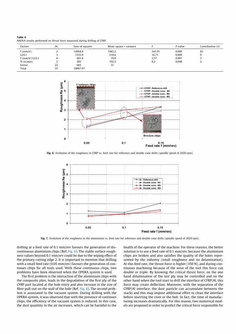
drilling at a feed rate of 0.1 mm/rev favours the generation of dis-continuous aluminium chips (Ref. Fig. 6). The stable surface rough-ness values beyond 0.1 mm/rev could be due to the wiping effect ofthe primary cutting edge 2. It is important to mention that drillingwith a small feed rate (0.05 mm/rev) favours the generation of con-tinues chips for all tools used. With these continuous chips, twoproblems have been observed when the OPERA system is used.
The first problem is the interaction of the aluminium chips withthe composite plies, leads to the degradation of the first ply of theCFRP part located at the hole entry and also increase in the size offibre pull-out on the wall of the hole (Ref. Fig. 8). The second prob-lem is associated to the vacuum system. During drilling with theOPERA system, it was observed that with the presence of continueschips, the efficiency of the vacuum system is reduced. In this case,the dust quantity in the air increases, which can be harmful to the
health of the operator of the machine. For these reasons, the bettersolution is to use a feed rate of 0.1 mm/rev, because the aluminiumchips are broken and also satisfies the quality of the holes repre-sented by the industry (small roughness and no delamination).At this feed rate, the thrust force is higher (350 N), and during con-tinuous machining because of the wear of the tool this force candouble or triple. By knowing the critical thrust force, on the onehand delamination of the last ply may be controlled and on theother hand when the tool start to drill the interface of CFRP/Al, thisforce may create deflection. Moreover, with the separation of theCFRP/Al interface, the dust particle can accumulate between thestacks and this may impose additional effort to clean the interfacebefore inserting the rivet or the bolt. In fact, the time of manufac-turing increases dramatically. For this reason, two numerical mod-els are proposed in order to predict the critical force responsible for
Table 4ANOVA results performed on thrust force measured during drilling of CFRP.
Factors DL Sum of squares Mean square = variance F P-value Contribution (%)
f (mm/tr) 2 14964.4 7482.2 241.01 0,000 83L2/L1 3 1555.9 518.6 16.71 0,000 9f (mm/tr)⁄L2/L1 6 497.4 79.9 2.57 0.007 3N (tr/min) 2 385 192.5 6.2 0.048 2Erreur 22 683 31Total 35 18067.67
0
1
2
3
4
5
6
0.05 0.1 0.15
Roug
hnes
s Ra
(µm
)
Feed rate f (mm/rev)
CFRP - Reference drillCFRP - Double cone - M1CFRP - double cone - M2CFRP - double cone - M3
Continues chips
Brocken chips
Fig. 6. Evolution of the roughness in CFRP vs. feed rate for reference and double cone drills (spindle speed of 2020 rpm).
0
1
2
3
4
5
6
0.05
Ro
ugh
ness
Ra
(µm
)
51.01.0Feed rate f (mm/rev)
Al - Reference drillAl - Double cone - M1Al - Double cone - M2Al - Double cone - M3
Fig. 7. Evolution of the roughness in the aluminium vs. feed rate for reference and double cone drills (spindle speed of 2020 rpm).

delamination at the hole exit and the one responsible for the sep-aration of the interface. Table 5 summarises the results observedduring drilling of CFRP/Al stacks.
3.2. Numerical study
3.2.1. Description of the numerical modelsTo analyse the impact of the highest measured thrust force with
the reference drill (twist drill) on the delamination at the exit sideof hole and to identify the behaviour at the interface of CFRP/Al,two numerical models are proposed. The numerical model is a3D model based on the use of 3D volume composite elements forthe carbon/epoxy plate and 3D volume elements for the alu-minium plate. In the first model, which leads to predict the delam-ination at the hole exit, one ply under the tool is considered. In thiscase, contact between tool and CFRP is modeled as a uniformly dis-tributed load located below the chisel edge of the tool (Ref. Fig. 9a).In addition, a pre-crack with a size of 0.05 mm is considered at thevicinity of the chisel edge. The critical thrust force responsible forthe delamination of the last ply is related to the critical energyrelease rate in mode I and mode II of the CFRP composite laminate.In fact, when the energy release rate in mode I and in mode II pre-dicted by the model satisfy, the criterion mentioned by the equa-tion 1, the applied force corresponds to the critical thrust force.
GI
GIC
! "a
þGII
GIIC
! "a
¼ 1 ð1Þ
where:
- GI: energy release rate in mode I predicted by the model.- GII: energy release rate in mode II predicted by the model.
- GIc: energy release rate in mode I which characterises the inter-face of the material.
- GIIc: energy release rate in mode II which characterises theinterface of the material.
- a: constant which depends on the nature of the CFRP (herea = 1.6).
The coefficient ‘‘a” being an empirical parameter derived fromthe best fit to data from mixed mode tests. ‘‘a” is generally in therange of 1–2 [48,49]. In this study, the value of ‘‘a” has been takenbased on the previous work of the authors [31]. More precisely,this value is equal to 1.6 as identified by Lévêque [48] for the samematerial. The second model is proposed in such a way that the chi-sel edge is in contact with the aluminium. For this, the contactbetween tool/multi-stacks is considered only between the chiseledge of the tool and the aluminium part (Ref. Fig. 9b). In this case,the deflection of the aluminium part below the chisel edge of thetool is analysed by considering load below the chisel edge. The con-tact condition between the tool and the aluminium is consideredas a uniformly distributed load with a circular surface area occu-pied by the chisel edge of the tool (1.2 mm). The amplitudes ofthe applied force are representative of those measured when thedrill is fresh and when the tool is considered worn. For the bothproposed models, the mechanical behaviour of the aluminium partis considered as a classical plastic with isotropic hardening. Thislaw is described in the work of Peech et al. [47].
3.2.2. Numerical resultsFig. 10 represents the evolution of the energy release rate in
mode I for different level of force. It is clear that with the increaseof the applied force, the computed energy release rate in mode I
)b()a(
Drilling directionDrilling direction
Damage areas
Damage areas
Fig. 8. 3D Cartographies of the damage located on the wall of the hole after drilling with a feed rate of 0.05 mm/rev and spindle speed of 2020 rpm. (a): drilling with referencedrill, (b) drilling with double cone drill M2.
Table 5Summarises the phenomena observed during drilling of CFRP/Al stacks.
Material/drill used Results observed
CFRP/referenceTool
High thrust force (min = 80 N, max = 122 N), roughness Ra < 2 lm for feedte <0.15 mm/rev and Ra > 3 lm for feed = 0.15 mm/rev
CFRP/double conedrill
Thrust force is mainly <by 20% compared to the thrust force generated by the reference drillRoughness Ra with double cone drill M2 is smaller to those obtained by the reference drill (Ra < 2 lm for feed <0.15 mm/rev). However, Raobtained with double cone drill M1 and M3 are superior by 50% compared to those obtained with the reference drill
Al/reference tool High thrust force (min = 174 N, max = 486 N), roughness Ra > 1 lm for any feed tested. Broken chips are observed when feed is P0.1 mm/revAl/double cone
drillThrust force obtained by the double cone drill M3 is < by 20% compared to other tools. Roughness obtained for any double cone drill is <by 40%compared to the roughness obtained by the reference drill

and mode II increase. For example, when the applied force variesfrom 100 N to 600 N, the energy release rate in mode I varies from0.01 N/mm to 0.25 N/mm. These values remain inferior to the crit-ical value when compared to the interface strength of the compos-ite plies which is 0.4 N/mm. This can be attributed to thealuminium plate located at the bottom of the CFRP laminate, whichblock the bending of the uncut layer of the CFRP and also the prop-agation of the crack. These results can be confirmed when the alu-minium plate thickness is reduced. In fact, when the aluminium
part has a thickness of 1 mm with an applied axial load of 400 N,the critical energy release rate in mode I reach the critical valueand the delamination can occur (Ref. Fig. 11). The critical thrustforce identified previously on the same composite during thequasi-static punching tests using twist drill show that the delami-nation of the last ply under the tool can occur when the criticalthrust force reach a value of 395 N [31]. This result confirm thatfor a thickness of aluminium part less than or equal to 1 mm thebending stiffness (of the aluminium) is low and can’t influencethe critical thrust force responsible for the delamination of the lastply of the composite.
In the Fig. 12a and b, cartographies of displacements ((OZ)direction) are illustrated for the applied load of 400 N and fortwo thicknesses of the aluminium part which are 3 mm and1 mm respectively. The applied force of 400 N corresponds to thecritical value responsible for the delamination of one ply underthe tool when drilling of the same material. This force has beenidentified in the previous study [31]. From these two cartographiesof displacement, it is clear that when the thickness of the alu-minium part is inferior or equal to 1 mm, the applied load inducesa local bending of the aluminium plate which favours delaminationat the hole exit (Ref. Fig. 12a). However, with the increase of thethickness of the aluminium part, the deflection phenomena is lesspronounced or inexistent (Ref. Fig. 12b). Thereby, this can removethe probability of the delamination at the hole exit.
When the active part of the drill reaches the interface of CFRP/Al, the analysis of the CFRP/Al interface shows that for an appliedforce of 160 N and when zero ply under the tool is considered a
(b)(a)
Force Force
Fig. 9. Cross section of the 3D model showing the mesh and boundary conditions (a): model with one ply under the tool, (b): model with zero ply under the tool.
0
100
200
300
400
500
600
700
0 0,05 0,1 0,15 0,2 0,25 0,3
Thu
rst f
orce
(N)
Energy release rate (N/mm)
GI (N/mm)
GII (N/mm)
Fig. 10. Impact of the applied thrust force on the predicted energy release rate inmode I and mode II.
0
0,05
0,1
0,15
0,2
0,25
0,3
0,35
0,4
0,45
0,5 1,5 2,5 3,5 4,5 5,5
En
erg
y re
leas
e ra
te (N
/mm
)
Thickness of Aluminium plate (mm)
Energy release rate in mode I (N/mm)
Energy release rate in mode II (N/mm)
Fig. 11. Evolution of the energy release rate in mode I and mode II as function of the thickness of the aluminium plate for an applayed thrust force of 400 N.

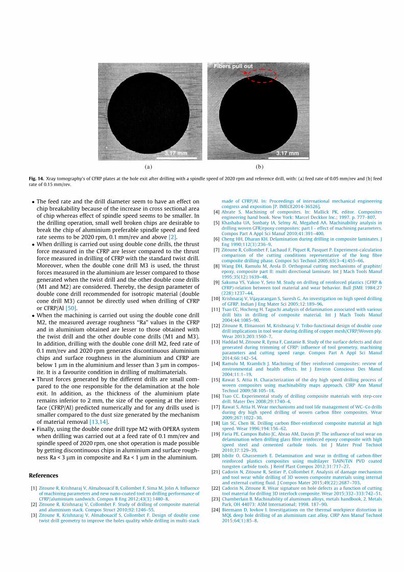
negligible amount of opening at the interface CFRP/Al is observed.The maximum size of this opening is around 0.23 lm when theapplied load is equal to 160 N (Ref. Fig. 13a). However, when theload reaches 400 N (feed rate of 0.15 mm/rev), the size of thisopening increases to 0.38 lm (Ref. Fig. 13b). Haddad et al.[13,14] reported that when machining T700/M21 carbon/epoxycomposite material, the major particles generated by the endmilling have a size of around 0.45 lm. In this case, when theapplied load is around 400 N, the carbon dust cannot pass throughthe CFRP/Al interface. Therefore, even in the most unfavorable sit-uation (high feed rate and thrust force), it is not necessary to sep-arate the parts (CFRP and aluminium) in order to clean theinterface before to put the rivets. However, if the thickness of thealuminium plate is around of 1 mm, the maximum size of thisopening is around 1.23 lm when the applied load is equal to160 N (Ref. Fig. 13c). In fact, in this situation the set up of the partsseparation is necessary in order to clean the interface before to putthe rivets. It is important to note that the results of the thrust forcemeasured using the Kistler dynamometer during drilling does notshow any drop in the thrust force when the chisel edge reachesthe CFRP/Al interface for both small and high feed rates. Thismay be confirmed by the fact that the predicted forces for delam-ination are higher compared to the measured forces for the feedrates and for the geometry of the twist drill used. In addition tothis, the X-ray tomography did not show any delamination defectat the exit side of the hole even for higher thrust force (Ref.Fig. 14a). However, by increase of the feed rate to 0.15 mm/rev,fibre pull-out and matrix degradation is observed (Ref. Fig. 14b).
4. Conclusion
In this paper, the impact of machining parameters and thedesign of double cone drill on the cutting forces and the machiningquality while drilling a multi-stack material made of CFRP laminateand aluminium plate have been investigated. From the experimen-tal and numerical analysis carried out, the following conclusionsare drawn:
' From this experimental and numerical study, it can also be con-cluded that the use of aluminium as back plate for CFRP delaythe delamination at the hole exit of the CFRP. However, whena thin aluminium plate is used (61 mm), it’s influence is negli-gible on the critical thrust force.
(a)
(b)
Aluminium thikness = 1 mm
Aluminium thikness = 3 mm
Fig. 12. Cartographies of the displacement follow (OZ) direction when 1 ply underthe reference tool is considered and an axial force of 400 N. With: (a) thickness ofthe aluminium part of 1 mm and (b) thickness of the aluminium part of 3 mm.
(a)
(b)
(c)
Aluminium thikness = 3 mm
Aluminium thikness = 3 mm
Aluminium thikness = 1 mm
Fig. 13. Cartographies of the displacement in the direction (OZ) when 0 ply underand the reference tool is considered. With (a): applied loading of 160 N andaluminium thickness of 3 mm, (b): applied loading of 400 N and aluminiumthickness of 3 mm and (c): applied loading of 160 N and aluminium thickness of1 mm.
' The feed rate and the drill diameter seem to have an effect onchip breakability because of the increase in cross sectional areaof chip whereas effect of spindle speed seems to be smaller. Inthe drilling operation, small well broken chips are desirable tobreak the chip of aluminium preferable spindle speed and feedrate seems to be 2020 rpm, 0.1 mm/rev and above [2].
' When drilling is carried out using double cone drills, the thrustforce measured in the CFRP are lesser compared to the thrustforce measured in drilling of CFRP with the standard twist drill.Moreover, when the double cone drill M3 is used, the thrustforces measured in the aluminium are lesser compared to thosegenerated when the twist drill and the other double cone drills(M1 and M2) are considered. Thereby, the design parameter ofdouble cone drill recommended for isotropic material (doublecone drill M3) cannot be directly used when drilling of CFRPor CFRP/Al [50].
' When the machining is carried out using the double cone drillM2, the measured average roughness ‘‘Ra” values in the CFRPand in aluminium obtained are lesser to those obtained withthe twist drill and the other double cone drills (M1 and M3).In addition, drilling with the double cone drill M2, feed rate of0.1 mm/rev and 2020 rpm generates discontinuous aluminiumchips and surface roughness in the aluminium and CFRP arebelow 1 lm in the aluminium and lesser than 3 lm in compos-ite. It is a favourite condition in drilling of multimaterials.
' Thrust forces generated by the different drills are small com-pared to the one responsible for the delamination at the holeexit. In addition, as the thickness of the aluminium plateremains inferior to 2 mm, the size of the opening at the inter-face (CFRP/Al) predicted numerically and for any drills used issmaller compared to the dust size generated by the mechanismof material removal [13,14].
' Finally, using the double cone drill type M2 with OPERA systemwhen drilling was carried out at a feed rate of 0.1 mm/rev andspindle speed of 2020 rpm, one shot operation is made possibleby getting discontinuous chips in aluminium and surface rough-ness Ra < 3 lm in composite and Ra < 1 lm in the aluminium.
References
[1] Zitoune R, Krishnaraj V, Almabouacif B, Collombet F, Sima M, Jolin A. Influenceof machining parameters and new nano-coated tool on drilling performance ofCFRP/aluminium sandwich. Compos B Eng 2012;43(3):1480–8.
[2] Zitoune R, Krishnaraj V, Collombet F. Study of drilling of composite materialand aluminium stack. Compos Struct 2010;92:1246–55.
[3] Zitoune R, Krishnaraj V, Almabouacif S, Collombet F. Design of double conetwist drill geometry to improve the holes quality while drilling in multi-stack
made of CFRP/Al. In: Proceedings of international mechanical engineeringcongress and exposition [P. IMECE2014-36526].
[4] Abrate S. Machining of composites. In: Mallick PK, editor. Compositesengineering hand book. New York: Marcel Deckker Inc.; 1997. p. 777–807.
[5] Khashaba UA, Sonbaty IA, Selmy AI, Megahed AA. Machinability analysis indrilling woven GFR/epoxy composites: part I – effect of machining parameters.Compos Part A Appl Sci Manuf 2010;41:391–400.
[6] Cheng HH, Dharan KH. Delamination during drilling in composite laminates. JEng 1990;112(3):236–9.
[7] Zitoune R, Collombet F, Lachaud F, Piquet R, Pasquet P. Experiment-calculationcomparison of the cutting conditions representative of the long fibrecomposite drilling phase. Compos Sci Technol 2005;65(3–4):455–66.
[8] Wang DH, Ramulu M, Arola D. Orthogonal cutting mechanisms of graphite/epoxy, composite part II: multi directional laminate. Int J Mach Tools Manuf1995;35(12):1639–48.
[9] Sakuma YS, Yakoo Y, Seto M. Study on drilling of reinforced plastics (GFRP &CFRP)-relation between tool material and wear behavior. Bull JSME 1984;27(228):1237–44.
[10] Krishnaraj V, Vijayarangan S, Suresh G. An investigation on high speed drillingof GFRP. Indian J Eng Mater Sci 2005;12:189–96.
[11] Tsao CC, Hocheng H. Taguchi analysis of delamination associated with variousdrill bits in drilling of composite material. Int J Mach Tools Manuf2004;44:1085–90.
[12] Zitoune R, Elmansori M, Krishnaraj V. Tribo-functional design of double conedrill implications in tool wear during drilling of copper mesh/CFRP/Woven ply.Wear 2013;203:1560–7.
[13] Haddad M, Zitoune R, Eyma F, Castanie B. Study of the surface defects and dustgenerated during trimming of CFRP: influence of tool geometry, machiningparameters and cutting speed range. Compos Part A Appl Sci Manuf2014;66:142–54.
[14] Ramulu M, Kramlich J. Machining of fiber reinforced composites: review ofenvironmental and health effects. Int J Environ Conscious Des Manuf2004;11:1–19.
[15] Rawat S, Attia H. Characterization of the dry high speed drilling process ofwoven composites using machinability maps approach. CIRP Ann ManufTechnol 2009;58:105–18.
[16] Tsao CC. Experimental study of drilling composite materials with step-coredrill. Mater Des 2008;29:1740–4.
[17] Rawat S, Attia H. Wear mechanisms and tool life management of WC–Co drillsduring dry high speed drilling of woven carbon fibre composites. Wear2009;267:1022–30.
[18] Lin SC, Chen IK. Drilling carbon fiber-reinforced composite material at highspeed. Wear 1996;194:156–62.
[19] Faria PE, Campos Rubio JC, Abrao AM, Davim JP. The influence of tool wear ondelamination when drilling glass fibre reinforced epoxy composite with highspeed steel and cemented carbide tools. Int J Mater Prod Technol2010;37:129–39.
[20] Isbilir O, Ghassemieh E. Delamination and wear in drilling of carbon-fiberreinforced plastics composites using multilayer TiAlN/TiN PVD coatedtungsten carbide tools. J Reinf Plast Compos 2012;31:717–27.
[21] Cadorin N, Zitoune R, Seitier P, Collombet F. Analysis of damage mechanismand tool wear while drilling of 3D woven composite materials using internaland external cutting fluid. J Compos Mater 2015;49(22):2687–703.
[22] Cadorin N, Zitoune R. Wear signature on hole defects as a function of cuttingtool material for drilling 3D interlock composite. Wear 2015;332–333:742–51.
[23] Chamberlain B. Machinability of aluminum alloys, metals handbook, 2. MetalsPark, OH 44073: ASM International; 1998. 187–90.
[24] Biermann D, Iovkov I. Investigations on the thermal workpiece distortion inMQL deep hole drilling of an aluminium cast alloy. CIRP Ann Manuf Technol2015;64(1):85–8.
)b()a(
3.17 mm 3.17 mm
Fibers pull out
Fig. 14. Xray tomography’s of CFRP plates at the hole exit after drilling with a spindle speed of 2020 rpm and reference drill, with: (a) feed rate of 0.05 mm/rev and (b) feedrate of 0.15 mm/rev.

[25] Ilyuschenko AP, Feldshtein EE, Lisovskaya YO, Markova LV, Andreyev MA,Lewandowski A. On the properties of PVD coating based on nanodiamond andmolybdenum disulfide nanolayers and its efficiency when drilling ofaluminium alloy. Surf Coat Technol 2015;270:190–6.
[26] Carrilero MS, Bienvenido R, Sanchez JM, Alvarez M, Gonzalez A, Marcos MA.SEM and EDS insight into the BUL and BUE differences in the turning processesof AA2024 Al–Cu alloy. Int J Mach Tools Manuf 2002;42. 215–20.
[27] Sanchez JM, Rubio E, Alvarez M, Sebastien MA, Marcos M. Microstructuralcharacterisation of material adhered over cutting tool in the dry machining ofaerospace aluminium alloys. J Mater Process Technol 2005;164–665:911–8.
[28] Brinksmeier E, Janssen R. Drilling of multi-layer composite materialsconsisting of carbon fibre reinforced plastics (CFRP), titanium andaluminium alloys. Ann CIRP 2002;51:87–90.
[29] Kim D, Ramulu M. Drilling process optimization for graphite/bismaleimidetitanium alloy stacks. Compos Struct 2004;63(1):101–14.
[30] Ramulu M, Branson T, Daehwa K. A study on the drilling of composite andtitanium stacks. Compos Struct 2001;54:67–77.
[31] Zitoune R, Collombet F. ‘‘Numerical prediction of the thrust force responsibleof delamination during the drilling of the long-fibre composite structures.Compos Part A Appl Sci Manuf 2007;38(3):858–66.
[32] Feito N, Puente JL, Santiuste C, Miguelez H. Numerical prediction ofdelamination in CFRP drilling. Compos Struct 2014;108:677–83.
[33] Abrao AM, Campos Rubio JC, Faria PE, Davim JP. The effect of cutting toolgeometry on thrust force and delamination when drilling glass fibre reinforcedplastic composite. Mater Des 2008;29(2):508–13.
[34] Gaitonde VN, Karnik SR, Rubio JC, Correia AE, Abrao AM, Davim JP. Analysis ofparametric influence on delamination in high-speed drilling of carbon fiberreinforced plastic composites. J Mater Process Technol 2008;203:431–8.
[35] Krishnaraj V, Zitoune R, Davim JP. Drilling of polymer matrixcomposites. Springer; 2013 [ISBN 978-3-642.38344-1].
[36] Rubio JC, Abrao AM, Faria PE, Correia AE, Davim JP. Effects of high speed in thedrilling of glass fibre reinforced plastic: evolution of the delamination factor.Int J Mach Tools Manuf 2008;48:715–20.
[37] Xu J, Mkaddem A, Mansori ME. Recent advances in drilling hybrid FRP/Ticomposite: a state-of-the-art review. Compos Struct 2016;135:316–38.
[38] Neugebauer R, Hanan U, Wabner M, Andrea S. Acoustic emission as a tool foridentifying drill position in fiber-reinforced plastic and aluminium stacks. Int JMach Tools Manuf 2012;57:20–6.
[39] Poutord A, Rossi F, Poulachon G, Saoubi RM, Abrivard G. Local approach ofwear in drilling Ti6Al4V/CFRP for stack modeling. Procedia CIRP2013;8:316–21.
[40] Shyha IS, Soo SL, Aspinwall DK, Bradley S, Perry R, Harden P, Dawson S. Holequality assessment following drilling of metallic-composite stacks. Int J MachTools Manuf 2011;51:569–78.
[41] Kuoa CL, Sooa SL. The effect of cutting speed and feed rate on hole surfaceintegrity in single-shot drilling of metallic-composite stacks. Procedia CIRP2014;13:405–10.
[42] Pecat O, Brinksmeier E. Low damage drilling of CFRP/titanium compoundmaterials for fastening. Procedia CIRP 2014;13:1–7.
[43] Pecat O, Brinksmeier E. Tool wear analyses in low frequency vibration assisteddrilling of CFRP/Ti6Al4V stack material. Procedia CIRP 2014;14:142–7.
[44] Wang X, Kwon PY, Sturtevant C, Kim D, Lantrip J. Comparative tool wear studybased on drilling experiments on CFRP/Ti stack and its individual layers. Wear2014;317:265–76.
[45] Abdelhafeez AM, Soo SL, Aspinwall DK, Dowson A, Arnold D. Burr formationand hole quality when drilling titanium and aluminium alloys. Procedia CIRP2015;37:230–5.
[46] Park KH, Beal A, Kim DW, Kwon P, Lantrip J. A comparative study of carbidetools in drilling of CFRP and CFRP-Ti stacks. J Manuf Sci Eng2014;136:014501–14509.
[47] Peech JM, Roener RE, Porofin SD, East GH, Goldstein NA. Local cruch rigidity ofpipes and elbows. In: Proc. 4th SMIRT conference [Paper F-3/8, North Holland].
[48] Lévêque D. ‘‘Analyse de la Tenue au Délaminage des Composites Stratifiés:Identification d’un Modèle d’Interface Interlaminaire”. Thèse de Doctorat del’Ecole Normale Supérieure de Cachan. 1998.
[49] Camanho PP, Hallett SR. Numerical modelling of fracture in advancedcomposite materials. Compos Sci Eng 2015;62 [ISBN 978-0-08-100332-9].
[50] Dalas DB. Tool and Manufacturing Engineers Handbook. SME; 1976 [chapter 3.pp. 16–17].