Embed Size (px)
Citation preview

Journal of Chromatography A, 811 (1998) 181–192
Experimental factors in pulsed electrochemical detection in capillaryelectrophoresis
*Jenny Wen, Richard M. Cassidy , Andrzej S. BaranskiChemistry Department, University of Saskatchewan, 110 Science Place, Saskatoon, SK S7N 5C9, Canada
Received 12 November 1997; received in revised form 26 March 1998; accepted 6 April 1998
Abstract
A number of experimental approaches that should offer improved S /N in electrochemical detection were evaluated andcompared. In addition, to evaluate and optimize the electrochemical response behavior of analytes under actual CEconditions, an on-line cyclic voltammetry (CV) system was developed. The experimental parameters examined includedwaveform shape, waveform frequency and various signal treatments, using a lock-in amplifier and Fourier analysis. Amultiple-step pulse waveform provided the maximum S /N enhancement [up to 10-fold relative to pulse amperometric
28 27detection (PAD)], with detection limits in the range of 2?10 to 2?10 mol / l. The use of the second harmonic from Fourieranalysis offered the best improvement in baseline stability. Other approaches such as high pulse frequency (100 to 200 Hz),data collection over selected time windows, digital filters and average smoothing also enhanced S /N 2- to 5-fold relative toPAD. On-line CV studies showed that the adsorption of organic electrolytes on electrode surfaces can inhibit O reactions,2
21and thus give low and stable background currents without O removal. The CV studies also showed that detection of Pb ,221 1 1Cu and Ag affected subsequent electrode response, and that H evolution contributed to the cathodic signals of the
21 21 21analytes Ni , Co and Zn . 1998 Elsevier Science B.V. All rights reserved.
Keywords: Electrochemical detection; Detection, electrophoresis; Cyclic voltammetry; Metal cations
1. Introduction amperometric approaches, constant-voltage detectionis the simplest. Direct reductive and oxidation meth-
Electrochemical detection is attractive for capillary ods with constant-voltage works well for the de-electrophoresis (CE) because mm-electrodes can termination of some analytes, such as catechols [1]provide small ohmic distortion in detection systems, and chlorophenol [2] however, inconsistent responsehigh sensitivities for small inner diameter (I.D.) is often observed due to electrode fouling fromcapillaries and rapid response when concentration or sample matrixes and/or analyte reaction productspotential is changed at the electrode. The fast [3,4]. One possible approach to prevent fouling ofresponse of mm-electrodes is particularly important the electrode surface is to apply pulsed potentials.for the application of high-frequency potential Pulsed amperometric detection (PAD) uses a multi-waveforms. Most electrochemical detection is based step potential waveform to detect analytes and toon amperometric detection principles. Of the various clean and reactivate the electrode surface. Since PAD
was introduced to liquid chromatography (LC) [5,6]*Corresponding author. it has been shown to improve the long-term stability
0021-9673/98/$19.00 1998 Elsevier Science B.V. All rights reserved.PI I : S0021-9673( 98 )00283-0

182 J. Wen et al. / J. Chromatogr. A 811 (1998) 181 –192
of electrode response for amino acids [7,8], carbohy- perimental conditions for some metal ions causeddrates [9,10] and sulfur-containing compounds poor response, deformed peaks, baseline-shifted[11,12]. In previous studies [13] we found that PAD peaks, and even negative peaks. These problemsof metal ions was reproducible (#5% over 14 h) appeared to be related to slow kinetics and/or the
25 27with detection limits in the range of 10 to 10 changes in the electrode surface as a result ofmol / l; these detection limits are similar to those interaction with the analytes or electrolytes. Sincereported for the PAD of other electroactive com- these problems are important for the optimization ofpounds in LC and CE [14–16]. Although these PAD in CE, there is a need to understand thedetection limits are sufficient for many samples, electrochemical behavior of analytes and co-existingthere are instances where lower detection limits are species at these electrodes. A possible approach thatrequired. Thus, it would be desirable if other more may help is on-line CE–cyclic voltammetry (CV).sensitive electrochemical detection approaches could CV is commonly used to study the thermodynamicsbe developed. and kinetics of electrochemical reactions at elec-
Possible parameters in PAD that may offer im- trode–solution interfaces, but with conventional CVproved signal-to-noise ratio (S /N) include waveform it is difficult to differentiate small analyte signalsshape, waveform frequency and signal analysis. from fluctuating background currents. Single-scanPrevious pulsed amperometric studies in LC and CE voltammetry has been used for open-tubular LC [24],have used a simple 2- or 3-step potential waveforms and multiple-step voltammetry has been used in CE[17–19], and frequencies of 1 to 8 Hz [19–21]. [25,26]. In a recent paper [26] it has been shown thatHigher frequencies should offer larger currents, and voltammetric detection with a fiber electrode inserteddifferent sensitivity for kinetically controlled pro- into a decoupled capillary presents serious resistancecesses (which under certain conditions can improve problems for scanning. The use of an end-capillarythe selectivity of detection). In addition, if the disk electrode should reduce these problems andapplied waveform contains sections where the po- permit much faster scanning, and permit applicationtential is cycled very rapidly, it may be possible to of CV waveforms.momentarily trap analytes at the electrode to permit The two main goals of the present study were:current measurements over several adsorption /de- firstly, develop on-line fast-scanning CV to examinesorption steps. An additional approach that may the electrochemical behavior of analytes and elec-improve S /N is to make use of current–voltage trolytes at low concentration levels used in CE; andcharacteristics that exist on the application of pulsed secondly, evaluate different experimental approachesvoltages to an electrode. The analysis of current for improvement of S /N in electrochemical CEvectors based on amplitude and phase-angle relation- detection. The parameters studied included wave-ships can help differentiate between faradaic and form shape, waveform frequency and data treatment,capacitance currents [22]; this approach may reduce such as vector and harmonic analysis. The testthe capacitance current component which is an analytes chosen for this study were a series of metalimportant part of background noise. Another ap- ions. These were selected because they show a wideproach for S /N enhancement is to utilize the differ- range of electrochemical behavior, and thus theent distributions of signal and noise in fundamental results should be representative of a number of otherand higher harmonic components. This approach can electroactive species.be achieved via both digital Fourier analysis andlock-in amplifiers. Recently, studies with a flowinjection system have shown that 2nd harmonics 2. Experimentalobtained from application of sinusoidal waveformmay offer some advantages for detection of carbohy- 2.1. CE apparatus and proceduresdrates at a Cu electrode [23]. All of these approachesoffer possible advantages, and it would be useful to Separation capillaries were 25 mm I.D.3350 mmhave a systematic study and comparison of them. O.D. (fused-silica, Polymicro Technology, Phoenix,
In our previous PAD studies [13] certain ex- AZ, USA) and were washed before use with water,

J. Wen et al. / J. Chromatogr. A 811 (1998) 181 –192 183
0.1 mol / l HCl and operating electrolytes [13] to USA, operated with a 0.1 s time constant. Cathodicobtain reproducible electroosmotic flow (EOF). EOF currents were designated as positive currents andwas monitored via the oxidation signal of catechol anodic currents as negative currents. For most of the(99%, Aldrich, Milwaukee, WI, USA), or via the present results, the relative error was ca. 0.01; threebaseline change after injecting water. For capillary to four measurements were made.storage, a flow of electrolyte was maintained at |10 Pulses for amperometric detection were eithercm height differential. The input of the high-voltage bipolar with a frequency of 5 to 1000 Hz, or(0 to 30 kV) power supply (Spellman, High Voltage consisted of a combination of several square pulsesElectronics, Plainview, NY, USA) was placed in a with different frequencies; these more complicatedPlexiglas box with an interlock switch on the access waveforms are discussed in Section 3.2. For mostdoor for protection. Analytes were introduced into PAD studies with a simple two-step waveform, thecapillaries via 5 kV electrokinetic or 10 cm hydro- analytes were reduced in the first part of the wave-dynamic injection for 10 s. Under these sampling form at 21200 to 2700 mV, and oxidation ofconditions, for hydrodynamic injection, the volume analytes was in the second step at 100 to 200 mVintroduced into the end of the capillary was calcu- [13]. For PAD with frequencies from 5 to 8 Hz, thelated [27] to be approximately 1.7 nl; and for analytical signal monitored was the average currentelectrokinetic injection, the amount of sample in- measured over the last 24, 48 or 72 ms of the
1 213jected [27] for Tl was 1.8?10 mol which was reduction pulse for cathodic analysis, and over theequal to the analyte in 3.7 nl of the sample solution, first 48 or 72 ms of the oxidative step for anodicand the sample volume injected into capillary by analysis. For PAD with frequencies of more than 7.5EOF was approximately 0.62 nl. Hz, the signal was selected by four different meth-
ods: the average current measured over whole reduc-2.2. Electrochemical system tion pulse for cathodic analysis; the average current
over whole oxidation pulse for anodic analysis; totalThe three-electrode electrochemical system con- current (cathodic current minus anodic current); and
sisted of a saturated KCl calomel reference electrode average cathodic and anodic current over one wave-(Fisher Scientific, Ottawa, Canada), a Pt wire (0.5 form pulse. These different approaches to data
2mm ) counter electrode, and 25 mm Au or Pt disk collection were used because the relationships be-working electrodes. In these present studies it was tween the factors contributing to S /N as waveformfound that the analytical performance of the Au frequencies are increased are complex, and theelectrodes was slightly better than that for Pt elec- optimum approach is difficult to predict.trodes, and consequently Pt electrodes were not used For PAD, and for most CV experiments, oxygenextensively in the quantitative aspects of these was not removed except as indicated. For the CVstudies. The construction and preconditioning of studies, the potential waveform had a conventionalworking electrodes has been described previously triangular shape combined with a preconcentration[13]. The alignment and distance between the elec- period: |50 ms at an initial potential (21200 totrodes and the end of the separation capillary (|20 2700 mV) and then scanned to a switching potentialmm) was adjusted with a XYZ micropositioner (2100 to 200 mV). The selection of the CV potential(Klinger, Garden City, NY, USA). The detection cell range depended on the standard potentials of ana-and potentionstat were placed in a Faraday cage to lytes. The voltammogram was recorded at |4000minimize environmental noise. Details of the con- data points per second (each point was an average ofstruction of the potentionstat has been described 10–17 A/D conversions). Several voltammogramselsewhere [28]. The electrochemical system was ($15) were obtained while a narrow analyte peakcontrolled with a pentium/16 MB RAM IBM per- passed by the working electrode.sonal computer equipped with a PCL-818 dataacquisition board (B&C Microsystem, Sunnyvale, 2.3. ReagentsCA, USA). The lock-in amplifier was a Model 5301,EG&G Princeton Applied Research, Princeton, NJ, All chemicals were of analytical grade and were

184 J. Wen et al. / J. Chromatogr. A 811 (1998) 181 –192
used without further purification. The solutions were 3. Results and discussionprepared from double-distilled deionized water(Corning, Mega-Pure system, MP-6A and D2, Corn- 3.1. On-line cyclic voltammetrying, NY, USA), and were stored in the dark. Thebackground electrolyte for separation and detection 3.1.1. Background CV studiesof the metal ions was 0.030 mol / l creatinine (Sigma, On-line CV was examined to determine if it couldSt. Louis, MO, USA) and 0.008 mol / l a-hydroxy- provide useful information about the electrochemicalisobutyric acid (HIBA) (98%, Aldrich), and the pH reactions occurring under the CE experimental con-value was adjusted with acetic acid (|30 mM) to 4.8. ditions. Since 25 mm Au and Pt electrodes hadThe electrolytes were remade every two to three provided good analytical response previously [13]months and were replaced daily in the separation these electrodes were chosen for these studies. Whenreservoir to avoid chemical and pH changes. Metal the distance between the end of the capillary and theion stock solutions (| 0.01 mol / l) were diluted to the electrode was more than 40 mm, the analytical signaldesired concentration with operating electrolyte prior decreased due to dilution, and when it was ,20 mm,to use. All CE solutions were filtered through a both background noise and the shift in the working-0.2-mm nylon-66 membrane syringe filter (Cole- electrode potential began to increase significantly.Parmer). Reagent grade metal salts used were: Thus the distance was adjusted to |2065 mm tothallium nitrate and nickel nitrate (Fisher Scientific, maximize S /N, to reduce peak broadening, and toFair Lawn, NJ, USA); lead nitrate, (Anachemia, maintain small potential shifts. For a wide range ofMontreal, Canada); cadmium nitrate and zinc nitrate experimental conditions the shift in electrode po-(Merck, Rahway, NJ, USA); silver acetate (BDH, tential observed on application of a 20 kV separationToronto, Canada); cobalt acetate (General Chemical voltage was in the range of 100 to 150 mV, butDivision, Allied Chemical and Dye, NY, USA); and week-to-week reproducibility of CV peak potentialcupric acetate (BDH, Toronto, Canada). was #50 mV. A scan rate of 20 V/s was used to
ensure that electrode behavior could be monitored at2.4. Signal analysis techniques several points across a narrow CE peak.
Electrolyte composition can influence the prop-The basic principles involved in the special data erties of the double layer at the electrode–solution
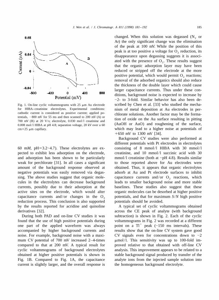
treatments used in these studies can be found else- interface, and this may affect electrochemical re-where [22]. Three of the approaches used involved actions at the electrode. To evaluate the role of theisolation of non-symmetrical analyte signals from the electrolytes used in this investigation, backgroundmore symmetrical background signals (e.g., capaci- cyclic voltammograms were studied at a Au elec-tance currents). When analyte reduction or oxidation trode in 8 mmol / l HIBA and 30 mmol / l creatinine.occurs the relation between current and potential is The results in Fig. 1A show that a peak appeared atsuch that different phase relationships are observed 2180 mV, which is the region expected for O2
for analyte and background signals. Also, because reduction. However, degassing (Ar or N ) did not2
current–potential relationships are described by an eliminate the peak, and caused little change in theexponential function, non-linear behaviour is ob- voltammogram. It is known [29,30] that some or-tained, which generates higher harmonics especially ganic compounds adsorb on Au and Pt surfaces, andwhen current–time dependencies for the reduction thus the peak at 2180 mV might be from theand the oxidation processes are significantly differ- adsorption of HIBA or creatinine at the electrode.ent. Thus one can expect that phase-sensitive de- Similar behavior, with slight shifts in shape andtection and/or harmonic analysis might lead to a position of the adsorption peak, was also observedsignificant improvement in S /N. In addition to the with succinic acid and creatinine, and with an aceticabove data treatment processes, standard Fourier- acid buffer. To help confirm that the peak resultedtransform filters, moving-average smoothing and from the adsorption of organic compounds at thepolynomial smoothing were also examined to im- electrode, cyclic voltammograms were recorded inprove S /N. phosphate, perchlorate and nitrate electrolytes (20–
J. Wen et al. / J. Chromatogr. A 811 (1998) 181 –192 185
changed. When this solution was degassed (N or2
Ar) the only significant change was the eliminationof the peak at 100 mV. While the position of thispeak is at too positive a voltage for O reduction, its2
disappearance upon degassing suggests it is associ-ated with the presence of O . These results suggest2
that the organic adsorption layer may have beenreduced or stripped off the electrode at the morepositive potential, which would permit O reactions;2
removal of the adsorbed organics should also reducethe thickness of the double layer which could causelarger capacitance currents. Thus under these con-ditions, background noise is expected to increase by|2- to 3-fold. Similar behavior has also been de-scribed by Chen et al. [33] who studied the mecha-Fig. 1. On-line cyclic voltammograms with 25 mm Au electrode
for HIBA–creatinine electrolytes. Experimental conditions: nism of metal deposition at Au electrodes in per-cathodic current is considered as positive current; applied po- chlorate solutions. Another factor may be the forma-tentials, 2800 mV for 55 ms and then scanned to 200 mV (A) or
tion of oxide on the Au surface resulting in pitting700 mV (B) at 20 V/s; electrolyte, 0.030 mol / l creatinine and(AuOH or AuO) and roughening of the surface,0.008 mol / l HIBA at pH 4.8; separation voltage, 20 kV over a 60which may lead to a higher noise at potentials ofcm325 mm capillary.
1650 mV to 1300 mV [34].Background CV studies were also performed at
different potentials with Pt electrodes in electrolytes60 mM, pH53.2|4.7). These electrolytes are ex- consisting of 8 mmol / l HIBA with 30 mmol / lpected to exhibit less adsorption on the electrode, creatinine, and 10 mmol / l succinic acid with 30and adsorption has been shown to be particularly mmol / l creatinine (both at |pH 4.8). Results similarweak for perchlorate [31]. In all cases a significant to those reported above for Au electrodes wereamount of the background response observed at obtained. Thus, it appears that organic electrolytesnegative potentials was easily removed via degas- adsorb at Au and Pt electrode surfaces to inhibitsing. The above studies suggest that organic mole- capacitance currents and/or O reactions, which2
cules in the electrolytes can decrease background leads to smaller background noise and more stablecurrents, possibly due to their adsorption at the baselines. These studies also suggest that theseactive sites on the electrode, which would alter organic molecules can be desorbed at higher positivecapacitance currents and/or changes in the O potentials, and that for maximum S /N high positive2
reduction process. This conclusion is also supported potentials should be avoided.by the results reported for acridine and quinoline A typical set of cyclic voltammograms obtainedderivatives [32]. across the CE peak of analyte (with background
During both PAD and on-line CV studies it was subtraction) is shown in Fig. 2. Each of the cyclicfound that the use of high positive potentials during voltammograms in Fig. 2 was recorded at a different
1one part of the applied waveform was always point on a Tl peak (|150 ms intervals). Theseaccompanied by higher background currents and results show that the on-line CV system gave goodnoise. For example, background noise with a maxi- CV signals even for concentrations down to |2mum CV potential of 700 mV increased 2–4-times mmol / l. This sensitivity was up to 100-fold im-compared to that at 200 mV. A typical result for proved relative to that obtained with off-line CVcyclic voltammograms of background electrolytes analysis. This improvement appears to be related to aobtained at higher positive potentials is shown in stable background signal produced by transfer of theFig. 1B. Compared to Fig. 1A, the capacitance analyte ions from the injected sample solution intocurrent is slightly larger, and the overall response is the homogeneous background electrolyte.

186 J. Wen et al. / J. Chromatogr. A 811 (1998) 181 –192
different electron transfer processes, but it was alsoobserved that the current collected in the presence of
21 1Cu and Ag was smaller than the current collected21 1in their absence. Thus, for Cu and Ag , changes
in background current may have important effects onthe observed cyclic voltammograms; reasons for thisbehavior are discussed below. The cyclic voltammo-grams of metal ions were also examined in 8 mmol / lsuccinic acid and 30 mmol / l creatinine. Similar peakshapes (relative to HIBA electrolyte) with slightshifts in peak potentials, were obtained. These shiftswere likely due to differences in stability constants,and/or differences in the adsorption of anions at the
1Fig. 2. On-line cyclic voltammograms across Tl peaks with 25 electrode. The cyclic voltammograms of analytes atmm Au electrode. Experimental conditions: applied potentials, Pt electrodes were similar to those obtained with Au2800 mV for 55 ms and then scanned to 200 mV at 20 V/s;
electrodes in both HIBA and succinic acid elec-analyte concentration, 50 mmol / l; 10 cm hydrodynamic injectiontrolytes.for 10 s; other conditions as in Fig. 1.
To examine the effect of repeated analyte injectionon the electrode response, cyclic voltammograms
3.1.2. Analyte CV studies were recorded over repeated CE separations (up toAs described in Section 1, deformed peaks, nega- five times). For single analytes and for mixtures, no
1 21tive peaks and irreproducible response were some- change in behavior was observed for Tl , Co ,21 21 21times observed in our previous PAD studies [13]. Ni , Zn and Cd . However, the behavior of21This behavior depended on the analytes present in a Pb was different. Although repeated injection of21mixture and on the analytes injected previously. To Pb did not affect the background cyclic volt-
help understand the factors affecting electrode re- ammograms, it did change the cyclic voltammo-21sponse of different analytes, on-line cyclic volt- grams of Pb and some other analytes. For exam-
21ammograms were obtained under a variety of ex- ple, the cyclic voltammograms of Cd before and1 21 21 21 21perimental conditions for Tl , Co , Ni , Zn , after repeated sampling with Pb are shown in Fig.
21 21 1Cd , Cu and Ag . The cyclic voltammograms of 3A and Fig. 3B, respectively. Fig. 3B shows that aall analytes were examined with and without back- new peak occurred at |100 mV and that the peakground subtraction to differentiate between direct potentials were shifted considerably. Some otherelectrochemical reaction of the analytes and changes metal ions also showed changes in their cyclicin background current (faradaic or capacitance). With voltammograms. These results suggest that the Au
1 21 21 21 21 1an Au electrode the metal ions Tl , Co , Ni , surface has been changed by Pb . Cu and Ag21 21Zn and Cd gave normal cyclic voltammograms showed even stronger effects on Au electrode re-
with no appreciable change in background current. sponse. Noise increased following the detection ofCyclic voltammograms of the analytes showed that these metal ions, and a decrease in background
21 1the differences between the cathodic and anodic peak current could be observed after Cu or Ag mi-potentials were: 0 to 50 mV for Tl, Pb; |200 mV for grated past the Au electrode. Because the back-Zn; and $500 mV for Cd, Ni and Co. These ground current came mainly from the adsorption ofdifferences in peak potentials and the cyclic volt- electrolytes and charging currents, the decrease ofammograms’ peak shapes implied that the rever- background current suggests that the organic ad-sibility of the electrochemical reactions were in the sorption might have been inhibited. Results reported
1following order (from fastest to slowest): Tl . for scanning tunneling microscopy studies [35] have21 21 21 21 21 21Pb 4Zn .Cd 4Ni and Co . In the cyclic suggested that deposition of Cu at Au and Pt
21 1voltammograms of Cu and Ag , two peaks were surfaces can induced changes in the electrode sur-21observed. These peaks seemed to represent two face. The cyclic volatmmograms of Cu were also

J. Wen et al. / J. Chromatogr. A 811 (1998) 181 –192 187
21 1for Cu and Ag , the best improvements wereobserved with a phosphate and a nitrate electrolyte.
21 21For Ni and Co , which did not show anyevidence for changes in the electrode surface in theabove studies, peak shape changes and baselineshifts after the peaks migrated were still observedunder certain conditions. A factor in this behavior
1may be a change in the electrode response for H1evolution. In principle, the rates of H evolution
1depend on the activation energy of the H reactionon the electrode surface [37], which is a function ofthe electrode material and its structure. In general,hydrogen has a high overvoltage on Hg, Pb, Tl, Cdand Zn surfaces; but on Fe, Ni, Co and Pt surfaces, alow overvoltage [38]. For the pH of the electrolytes
1(4.8), H evolution occurs at a potential #210001 21 21 21 1mV. For Tl , Pb , Cd , Cu and Ag detection
1the potential could be adjusted to avoid H evolu-21 21 21tion, but for Zn , Ni and Co a potential of
1#21000 mV is needed. The H evolution observedin the cyclic voltammograms showed a decrease for
21 21 2121 Zn , and an increase for Ni and Co . TheseFig. 3. Effect of injection of Pb samples on subsequent cyclic121voltammograms across Cd peaks at 25 mm Au electrode. changes are consistent with the H overvoltage
Experimental conditions: applied potentials, 2900 mV for 55 ms properties of the metals. Therefore, metal ion peaksand then scanned to 300 mV at 20 V/s; analyte concentration, 50 can contain responses both from the reactions ofmmol / l; electromigration injection at 5.0 kV for 10 s; other 1
21 metal ions and H . In addition, small changes in theconditions as in Fig. 1. (A) before injection of Pb ; (B) after the121 electrode surface could alter H evolution, and thuselectrode was used to detect five Pb samples.
result in baseline shifts. These problems can beavoided if detection occurs during the anodic portion
examined in phosphoric and nitric acids, and both of a PAD pulse, which is not a limitation becausegave normal cyclic voltammogram peaks. These this mode of data analysis usually gives maximumresults further confirm that the decrease of back- S /N.ground current was caused by the inhibition oforganic adsorption. Similar results were also ob- 3.2. Waveform shape and signal enhancementserved at Pt electrodes. The change of backgroundcurrent led to small or even negative signals for Previous PAD studies with a simple bipolar wave-
21 1 25Cu and Ag , and this explains the negative peaks form gave detection limits in the range of 2?10 to27sometimes observed for these metal ions with PAD. 2?10 mol / l [13] (note that comparisons of tech-
The nature of the changes in the Au and Pt surfaces niques described later are made relative to these PAD21induced by the electrochemical reactions of Pb , detection limits). The use of a multistep waveform
21 1Cu and Ag is not known for certain. Incomplete should offer improved S /N for two main reasons.removal of the analyte is a possibility, and substan- Firstly, multistep waveforms will permit the sepa-tial roughening of the electrode surface has been ration of the measurement voltage from large volt-found by atomic force microscopy studies [36] for ages that may be required for electrode cleaningrepeated deposition and stripping; such roughening is and/or for rapid sample deposition. Secondly, theexpected to change the cyclic voltammograms of use of fast (relative to rates of diffusion) multiple-
21analytes. To reduce these effects for Pb , the use of steps during signal measurement may enhance S /Na higher CV potential (400 mV) was effective, but due to multiple adsorption–desorptions of the ana-

188 J. Wen et al. / J. Chromatogr. A 811 (1998) 181 –192
lyte. In an effort to improve and widen the applica- three-fold enhancement in detection limits comparedtion of PAD, different parameters of the pulse to those obtained previously for anodic PAD [13].waveform were examined over the concentration The shape of a typical multiple-step waveform
26 25range of 1?10 to 5?10 mol / l; these parameters used is shown in Fig. 5. A wide variety of conditionsincluded waveform shape, waveform frequency and were examined over the concentration range of 1?
26 25data collection within the pulse waveform. 10 to 2?10 mol / l, but in general the preconcen-According to the Cottrell equation [39], analyte tration period (t ) was at 2800 to 21200 mV for 100p
and background signals observed upon the applica- to 200 ms, and signal measurement was made duringtion of a voltage pulse are related to pulse frequency, the fast bipolar pulses applied with frequencies of 20and the signal /environmental noise should also to 200 Hz over a period 100 to 200 ms; the cleaningincrease with frequency; thus certain frequencies period was at 400 to 500 mV for |100 ms. Themay give larger S /N. In previous studies with a analytical signal used for the evaluation of differentsimple bipolar pulse [13], frequencies from 4 to 8 Hz waveform shapes was the average current measuredwere used, and in this work signals were evaluated over the high-frequency pulses. The results showedover the frequency range of 7.5 Hz to 600 Hz for that signals increased quickly for values of t up top
1 21 21 21Tl , Zn , Cd and Pb . Square-wave pulses 100 ms for all analytes; the rate of increase slowedwere applied to the electrode, and the total current down at t .100 ms. Deposition times .200 msp
was measured. The results in Fig. 4 show that for decreased reproducibility of electrode response (re-1 21Tl the analytical signal increased with pulse fre- petitive injection R.S.D..5%). For Pb , which
quency, that peak-to-peak noise was at a minimum at adsorbed strongly on the electrode, a high cleaning200 Hz, and that maximum S /N occurred at 180– potential improved peak shape and S /N; peak width280 Hz. The general trends observed for the other was reduced more than 50% and S /N improved up to
1metal ions were similar to those for Tl . The 2- to 3-fold when a cleaning potential of 400 mV wasconditions for maximum S /N (180|280 Hz) gave a applied for 100 ms. The application of voltage
oscillations during data collection (center portion ofFig. 5) improved S /N by effectively trapping theanalyte via repeated oxidation–reduction. Over the
Fig. 4. Effect of bipolar pulse frequency on analytical andbackground signals. y-Scale is mA for signal, 0.1 mA for noise andS /N values have been divided by 10. Experimental conditions: Fig. 5. Multiple-step waveform applied to electrodes. Experimen-cathodic current is considered as positive current; applied po- tal conditions: y-scale voltages depended on experiment; initialtentials, 2800 mV for reduction and 200 mV for oxidation; preconcentration periods were at 2800 to 21200 mV (dependinganalytical signal was an average current measured over the on analytes) for 100 to 200 ms; signal measurement was made
1cathodic and anodic current; errors, 67%; analyte (Tl ) con- during application of the fast bipolar pulses with frequencies of 20centration, 2.0 mmol / l; 5 kV electrokinetic injection for 10 s; other to 200 Hz over a period 100 to 200 ms; the cleaning period was atconditions as in Fig. 1. 400 to 500 mV for |100 ms.

J. Wen et al. / J. Chromatogr. A 811 (1998) 181 –192 189
frequency range studied (20–200 Hz) the S /N in- to-peak noise was also a maximum at the same point,creased slowly to give a |3-fold improvement in the S /N was still a maximum at 0.2 ms. Theoretically,range of 50–500 Hz. Above 200 Hz, background maximum electrode response should immediatelynoise increased faster than analyte signals. Relative follow the change of potential polarity, and the smallto previous results (see start of this section) obtained delay observed in Fig. 6 may be a result of delays in
28with a simple bipolar pulse, detection limits (2?10 the data acquisition board; such shifts have been27to 2?10 mol / l) were improved by up to 10-fold for reported elsewhere [40]. When the optimal sampling
1 21Tl and Pb , and by 4–6 fold for the other metal period (|0.2) ms was used for CE separation of theions studied. Cleaning periods of |100 ms in the test metal ions over the concentration range of 5.0?
26 24waveform were sufficient to prevent longer-term 10 to 1.0?10 mol / l it was found that the anodicaccumulation of the analytes, which would cause signal gave slightly better detection limits (by |2:1).peak broadening. The maximum pulse length was However, these detection limits were poorer thanlimited to 400 ms to permit the collection of 10 data those observed previously for integration of thepoints for a 4 s peak. whole anodic signal, and thus this was not investi-
Since the ratio of background and faradaic cur- gated further.rents also depends on the location of data samplingwithin a pulse, optimizing of the data collection 3.3. Signal analysis techniquesperiod may provide larger S /N. To find the samplinglocation having maximum S /N, a 180 Hz frequency 3.3.1. Harmonic analysisbipolar pulse was sampled over 64 equal sampling As discussed above, Fourier analysis of PAD
1 21 21 21periods for Tl , Zn , Cd and Pb : each period currents might offer a technique to differentiatewas |0.087 ms. All analytes exhibits similar trends, between the symmetrical double-layer capacitance
1 21and the response for Tl and Cd across one currents and the less symmetrical faradaic currents.square-wave pulse at the maximum of the CE peaks To determine if this approach might improve S /Nare shown in Fig. 6. For both anodic and cathodic the magnitudes of the different harmonics were
1 21 21signals, maximum response was obtained at |0.2 ms examined for the CE separation of Tl , Cd , Pb ,21 21 21after the change of potential polarity. Although peak- Zn , Ni and Co , over the concentration range
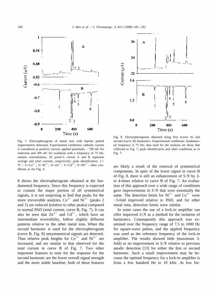
24 26of 1?10 to 5?10 mol / l with a PAD frequencyrange of 7.5 to 120 Hz. A typical response observedfor a CE separation with normal PAD obtained byapplication of a 75 Hz square-wave pulse is shown inFig. 7. The CE data in this Figure has been displayedas both the average current (curve A) and as the totalcurrent (curve B, cathodic–anodic). Both curves inFig. 7 exhibit a shifted baseline, a feature oftenobserved for these analytes when cathodic currentscontribute to the signal used for analysis (see Section3.1). The average-current response is expected to besmaller for symmetrical signals (fast, reversiblereactions), and this is one of the reasons for thedifference in relative peak heights between curves Aand B in Fig. 7. The S /N for the peaks in curve B aresimilar to previous results for anodic detection [13],
1 21Fig. 6. Response for Tl and Cd at different points of applied but baseline stability was much poorer becausebipolar pulse. Experimental conditions: applied bipolar pulse cathodic currents were part of the analytical re-potentials, 21000 mV for reduction and 300 mV for oxidation
sponse. The S /N values in curve B were used as awith a frequency of 180 Hz; analytical data were collected overstandard for comparison of the different signal-per-each short period (0.087 ms); errors, 66%; analyte concentration,
20 mmol / l; other conditions as in Fig. 4. ceiving techniques discussed below. Curve A in Fig.
190 J. Wen et al. / J. Chromatogr. A 811 (1998) 181 –192
Fig. 8. Electropherograms obtained using first (curve A) andFig. 7. Electropherogram of metal ions with bipolar pulsed second (curve B) harmonics. Experimental conditions: fundamen-amperometric detection. Experimental conditions: cathodic current tal frequency is 75 Hz; data used for the analysis are those thatis considered as positive current; applied potentials, 2700 mV for collected in Fig. 7; peak identification and other conditions as inreduction and 300 mV for oxidation with a frequency of 75 Hz; Fig. 7.analyte concentration, 50 mmol/ l; curves A and B representaverage and total currents, respectively; peak identification, 15
1 21 21 21 21 21Tl ; 25Co ; 35Ni ; 45Zn ; 55Cd ; 65Pb ; other con- are likely a result of the removal of symmetricalditions as for Fig. 4.
components. In spite of the lower signal in curve Bof Fig. 8, there is still an enhancement of S /N by 2-
8 shows the electropherogram obtained at the fun- to 4-times relative to curve B of Fig. 7. An evalua-damental frequency. Since this frequency is expected tion of this approach over a wide range of conditionsto contain the major portion of all symmetrical gave improvements in S /N that were essentially the
21 21signals, it is not surprising to find that peaks for the same. The detection limits for Ni and Co were21 21more irreversible analytes, Co and Ni (peaks 2 |3-fold improved relative to PAD, and for other
and 3) are reduced (relative to other peaks) compared metal ions, detection limits were similar.to normal PAD (total current, curve B, Fig. 7). It can In some cases the use of a lock-in amplifier can
21 21also be seen that Zn and Cd , which have an offer improved S /N as a method for the isolation ofintermediate reversibility, follow slightly different harmonics. Consequently this approach was ex-patterns relative to the other metal ions. When the amined over the frequency range of 7.5 to 1000 Hzsecond harmonic is used for the electropherogram for square-wave pulses, and the applied frequency(curve B, Fig. 8) unsymmetrical signals are detected. was used as the reference frequency of the lock-in
21 21Thus relative peak heights for Co and Ni are amplifier. The results showed little (maximum 3-increased, and are similar to that observed for the fold) or no improvement in S /N relative to previoustotal current in curve B of Fig. 7. Two other anodic detection [13] for either the first or secondimportant features to note for the response for the harmonic. Such a small improvement may be be-second harmonic are the lower overall signal strength cause the optimal frequency for a lock-in amplifier isand the more stable baseline; both of these features from a few hundred Hz to 10 kHz. At low fre-

J. Wen et al. / J. Chromatogr. A 811 (1998) 181 –192 191
quencies, 1 /f noise, including both that developed in better than that for the harmonic analysis conditionsthe Model 5301 lock-in amplifier and that originating used in Fig. 8.in the experiment itself, may have limited the S /N ofthe lock-in amplifier for low-frequency signals. Athigh frequencies, the lock-in amplifier could not 4. Conclusionsdifferentiate the analytical signal from the back-ground noise. Of the various approaches examined for the
enhancement of analytical S /N, the best results were3.3.2. Phase sensitive detection obtained with the addition of a multiple-step po-
An alternative approach for minimizing contribu- tential waveform to a bipolar pulse. The up to 10-28tions from capacitance currents is to treat the cur- fold improvements (detection limits in 2?10 to
27rents as vectors and to use a phase angle shift to 2?10 mol / l range) observed relative to PAD areminimize contributions from charging currents (see mainly applicable to species that can be concentratedSection 2.4). The results for this approach with the at the electrode, but such approaches may also provefirst and second harmonics are shown in Fig. 9. useful for analytes that physically adsorb at electrodeAgain, the best improvements in S /N were seen for surfaces. Although the harmonic analysis techniques
21 21Co and Ni , and in general the trends are similar offered improved baseline stability, the smaller im-to those shown in Fig. 8. Thus the second harmonic provements in S /N (3- to 6-fold for vector approach)response, curve B in Fig. 9, showed improved make this approach a bit less attractive. However,baseline stability and better S /N. The improvements this procedure may prove useful for application toin S /N were 3- to 6-fold relative to total current analytes that cannot be preconcentrated at the elec-(curve B, Fig. 7), and thus this approach is slightly trode surface. Digital filtering and data smoothing
techniques can also be used to further improve S /N.A brief examination of these techniques showedimprovements of 2–5-fold, but a controlled studywas not made for all the different approachesexamined for PAD in this paper. Another detectionapproach, which has not been examined in thesestudies, is the use of rapid-scanning CV. From thepreliminary work done here to characterize elec-trode–analyte interactions it is apparent that this typeof CE detection may combine sensitive detectionwith analyte characterization. This aspect will be thesubject of a future investigation.
Acknowledgements
The authors acknowledge the Natural Science andEngineering Research Council of Canada and theWaters Corp. for financial assistance to certainportion of this research.
ReferencesFig. 9. Electropherograms obtained using first (curve A) andsecond (curve B) harmonics from vector analysis. Experimental [1] R.A. Wallingford, A.G. Ewing, Anal. Chem. 59 (1987) 1762.conditions as in Fig. 7. [2] C.D. Gaitonde, P.V. Pathak, J. Chromatogr. 514 (1990) 389.

192 J. Wen et al. / J. Chromatogr. A 811 (1998) 181 –192
[3] D.S. Austin, J.A. Polta, J. Electroanal. Chem. 168 (1984) [22] A.J. Bard, L.R. Faulkner, Electrochemical Methods – Fun-227. damental and Applications, Wiley, New York, 1980, Ch. 9.
[4] S.E. Moring, in: P.D. Grossman, J.C. Colburn (Eds.), Capil- [23] P. Singhal, W.G. Kuhr, Anal. Chem. 69 (1997) 3552.lary Electrophoresis – Theory and Practice; Quantitative [24] J.G. White, J.W. Jorgenson, Anal. Chem. 58 (1986) 2992.Aspects of Capillary Electrophoresis Analysis, Academic [25] S.S. Ferris, G. Lou, A.G. Ewing, J. Microcol. Sep. 6 (1994)Press, San Diego, CA, 1992. 263.
[5] D. Clark, M. Fleishman, D. Pletcher, J. Electroanal. Chem. [26] S. Park, M.J. McGrath, M.R. Smyth, D. Diamond, C.E.37 (1972) 137. Lunte, Anal. Chem. 69 (1997) 2994.
[6] A. MacDonald, P.D. Duke, J. Chromatogr. 83 (1973) 331. [27] P. Jandik, G. Bonn, Capillary Electrophoresis of Small[7] J.A. Polta, D.C. Johnson, J. Liq. Chromatogr. 6 (1983) 1726. Molecules and Ions, VCH, New York, 1993, Ch. 3.[8] L.E. Welch, W.R. LaCourse, D.A. Mead Jr., T. Hu, D.C. [28] W. Lu, R.M. Cassidy, A.S. Baranski, J. Chromatogr. 640
Johnson, Anal. Chem. 61 (1989) 555. (1993) 433.[9] S. Hughes, D.C. Johnson, Anal. Chim. Acta 149 (1983) 1. [29] P. Avouris, J.E. Demoth, J. Chem. Phys. 75 (1981) 4783.
[10] W.R. LaCourse, D.A. Mead Jr., D.C. Johnson, Anal. Chem. [30] L. Stolberg, J. Lipkowski, D.E. Irish, J. Electroanal. Chem.62 (1990) 220. 296 (1990) 271.
[11] J.A.M. vanRiel, C. Olieman, Anal. Chem. 67 (1995) 3911. [31] A. Hamelin, J. Electroanal. Chem. 138 (1982) 395.[12] A. Ngoviwatchai, D.C. Johnson, Anal. Chim. Acta 215 [32] A.J. Bard, L.R. Faulkner, Electrochemical Methods – Fun-
(1988) 1. damental and Applications, Wiley, New York, 1980, Ch. 12.[13] J. Wen, R.M. Cassidy, Anal. Chem. 68 (1996) 1047. [33] C.-H. Chen, S.M. Vesecky, A.A. Gewirth, J. Am. Chem. Soc.[14] I. Morita, J. Sawada, J. Chromatogr. 641 (1993) 375. 114 (1992) 451.[15] F.M. Everaerts, T.P.E.M. Verheggen, F.E.P. Mikkers, J. [34] D.J. Trevor, C.E.D. Chidsey, D.N. Loiacona, Phys. Rev. Lett.
Chromatogr. 169 (1992) 341. 62 (1989) 929.[16] R.L. Chien, D.S. Burgi, Anal. Chem. 64 (1992) 1046. [35] A. Bewick, B. Thomas, J. Electroanal. Chem. 84 (1977) 127.[17] A. Hussam, Anal. Chem. 60 (1988) 2776. [36] V. Jovic, B. Jovic, A. Despic, J. Electroanal. Chem. 288[18] C.W.K. Chow, D.E. Davey, D.E. Mulcahy, T.C.W. Yeow, (1990) 229.
Anal. Chim. Acta 307 (1995) 15. [37] R. Parsons, Trans. Faraday Soc. 54 (1958) 1035.[19] P.W. Alexander, J. Koopetngram, Anal. Chim. Acta 197 [38] H. Gerischer, Trans. Faraday Soc. 67 (1958) 506.
(1987) 353. [39] D.K. Gosser, Cyclic Voltammetry – Simulation and Analysis[20] W. Matuszewski, A. Hulanicki, M. Trojanowicz, Anal. Chim. of Reaction Mechanisms, VCH, New York, 1993.
Acta 194 (1987) 269. [40] W. Lu, R.M. Cassidy, Anal. Chem. 63 (1993) 2878.[21] T.J. O’Shea, S.M. Lunte, Anal. Chem. 65 (1993) 948.