Embed Size (px)
Citation preview

1
Experimental Implementation of a NewNon-redundant 6-DOF Quadrotor Manipulation
SystemAhmed Khalifa and Mohamed Fanni
Abstract—This paper presents an experimental validation ofa new quadrotor-based aerial manipulator. A quadrotor isequipped with a 2-DOF robotic arm that is designed with a newtopology to enable the end-effector of the whole system to track a6-DOF trajectory. An identification experiment is carried out tofind out the system parameters. The mathematical model of thewhole system is presented. A measurement scheme is proposedto get the accurate pose of the vehicle considering the motionof the manipulator below the quadrotor. The system controlleris designed and implemented based on PID with a gravitycompensation algorithm. System simulation is implemented in theMATLAB/SIMULINK environment with real system parameters,to better emulate a realistic setup. Real-time Experiments areconducted. Both simulation and experimental results show thefeasibility and a satisfactory efficiency of the proposed system inachieving the position holding and transferring an object to aspecific target position.
Index Terms—Aerial manipulation, 6-DOF Positioning system,Identification, Position Holding, PID with gravity compensation.
I. INTRODUCTION
UNMANNED Aerial Vehicles (UAVs) particularly multi-rotors type, receive great attention due to their higher
degree of mobility, speed and capability to access to regionsthat are inaccessible to ground vehicles. However, UAV asa standalone vehicle has limited functionality to the searchand surveillance applications. Their distinguished mobilitynominates them to be utilized for aerial manipulation. Thesesystems open new application area for robotics such as in-spection, maintenance, structure assembly, firefighting, rescueoperation, or transportation in locations that are inaccessible,very dangerous or costly to be accessed from the ground.
Research on quadrotor-based aerial manipulation has dif-ferent approaches, [1], based on the tool attached to thequadrotor including gripper [2], cables [3], [4], multi-DoFrobotic manipulator [5], [6], multi-DoF dual-arms manipulator[7], compliant manipulator [8], and Hybrid rigid/elastic-jointmanipulator [9].
In the gripper-based approach, the attitude of quadrotor thepayload is restricts that of the gripper, as a result, the end-effector has four independent DOF; three translational and one
A. Khalifa is with the department of Industrial Electronics and ControlEngineering, Faculty of Electronic Engineering, Menofia University, Egypt,[email protected].
M. Fanni is with the department of Mechatronics and Robotics Engineering,Egypt-Japan University of Science and Technology. On leave from Departmentof Production Engineering and Mechanical Design, Mansoura University,Egypt.
rotational DOF. The second approach that uses cables suffersfrom the unexpected motion of the payload. To cope up withthese limitations, another approach is proposed in which a arobotic arm is attached to a quadrotor. An aerial manipulatorconsisting of a quadrotor and a 2-DOF robotic arm is presentedin [5]. However, this system has a manipulator with a topologythat limits the motion of the end-effector to make an arbitraryposition and orientation. This is because the axes of both jointsare parallel to one in-plane axis of the quadrotor. Therefore,without moving the quadrotor horizontally, the system cannotdo orientation about the second in-plane axis of it.
In [10], [6], the authors propose a new quadrotor-basedaerial manipulation system in which the manipulator has withtwo revolute joints whose axes are normal to each other andthe axis of the first joint is parallel to one in-plane axis ofthe quadrotor. Thus, the end-effector is able to reach arbitraryposition and orientation without moving the quadrotor hori-zontally.
In this research, mathematical modeling of the system ispresented. The whole system is built and its parameters areidentified. Furthermore, experimental setup with a simplesolution to the problem of the positioning of the quadrotormanipulation system is introduced taking into considerationthe position of the manipulator with respect to the sensors.This solution is based on a combination of several sensorsand data fusion. Quadrotor/joint space control is designedand implemented in simulation and real time based on PIDwith gravity compensation technique. An experimental test iscarried out to demonstrate the feasibility and the effectivenessof the proposed approach in the presence of holding a payload.
The main contributions of this article are as follows:• Implementation and validation of a quadrotor-based aerial
manipulator, which utilizes a 2-link robotic arm with atopology that enables the end-effector to track a desired6-DOF trajectory.
• A solution to the problem of the accurate positioning ofthe quadrotor manipulation system is introduced.
• An experimental study is conducted to demonstrate sys-tem capabilities.
II. PLATFORM DESCRIPTION
Fig. 1 shows a 3D CAD model of the proposed aerialmanipulator. System geometrical frames, which are assumed tosatisfy the Denavit-Hartenberg (DH) convention, are illustratedin Fig. 2. The manipulator has two revolute joints. The axis
arX
iv:1
903.
1200
1v1
[cs
.RO
] 2
8 M
ar 2
019
2
Fig. 1: 3-D CAD model of the proposed system
Fig. 2: Schematic of Quadrotor Manipulation System withrelevant frames
Fig. 3: Prototype of the proposed aerial manipulator
of the first joint, z0, is parallel to the quadrotor x-axis. Theaxis of the second joint, z1, is normal to that of the first jointand hence it is parallel to the quadrotor y-axis at the extendedconfiguration. Therefor, the pitching and rolling rotation of theend-effector is allowable independently from the horizontalmotion of the quadrotor. Hence, with this proposed aerialmanipulator, it is possible to manipulate objects with arbitrarylocation and orientation.
A. Hardware
The prototype of the proposed system is presented in Fig.3. Fig. 4 shows the proposed experimental implementationof the whole connected system with the user interface andmeasurement system.
A quadrotor, Asctec pelican type [11], is equipped with4 rotors with 10 inch diameter, which allow to carry an
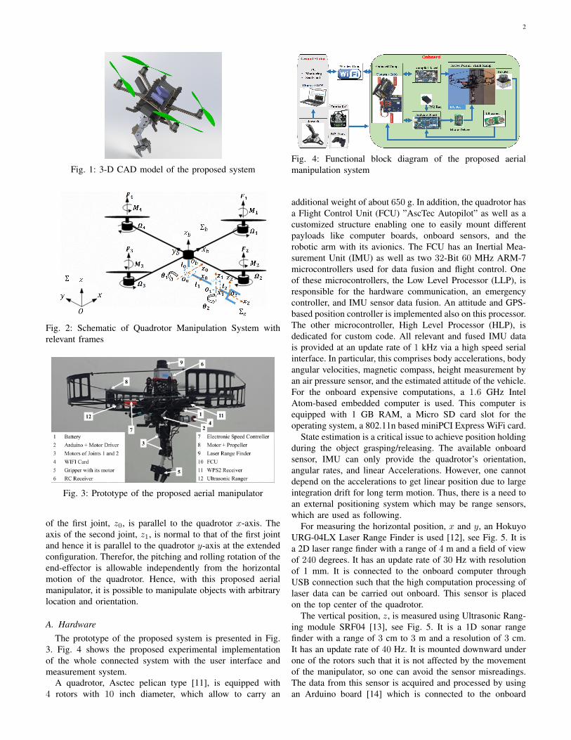
Fig. 4: Functional block diagram of the proposed aerialmanipulation system
additional weight of about 650 g. In addition, the quadrotor hasa Flight Control Unit (FCU) ”AscTec Autopilot” as well as acustomized structure enabling one to easily mount differentpayloads like computer boards, onboard sensors, and therobotic arm with its avionics. The FCU has an Inertial Mea-surement Unit (IMU) as well as two 32-Bit 60 MHz ARM-7microcontrollers used for data fusion and flight control. Oneof these microcontrollers, the Low Level Processor (LLP), isresponsible for the hardware communication, an emergencycontroller, and IMU sensor data fusion. An attitude and GPS-based position controller is implemented also on this processor.The other microcontroller, High Level Processor (HLP), isdedicated for custom code. All relevant and fused IMU datais provided at an update rate of 1 kHz via a high speed serialinterface. In particular, this comprises body accelerations, bodyangular velocities, magnetic compass, height measurement byan air pressure sensor, and the estimated attitude of the vehicle.For the onboard expensive computations, a 1.6 GHz IntelAtom-based embedded computer is used. This computer isequipped with 1 GB RAM, a Micro SD card slot for theoperating system, a 802.11n based miniPCI Express WiFi card.
State estimation is a critical issue to achieve position holdingduring the object grasping/releasing. The available onboardsensor, IMU can only provide the quadrotor’s orientation,angular rates, and linear Accelerations. However, one cannotdepend on the accelerations to get linear position due to largeintegration drift for long term motion. Thus, there is a need toan external positioning system which may be range sensors,which are used as following.
For measuring the horizontal position, x and y, an HokuyoURG-04LX Laser Range Finder is used [12], see Fig. 5. It isa 2D laser range finder with a range of 4 m and a field of viewof 240 degrees. It has an update rate of 30 Hz with resolutionof 1 mm. It is connected to the onboard computer throughUSB connection such that the high computation processing oflaser data can be carried out onboard. This sensor is placedon the top center of the quadrotor.
The vertical position, z, is measured using Ultrasonic Rang-ing module SRF04 [13], see Fig. 5. It is a 1D sonar rangefinder with a range of 3 cm to 3 m and a resolution of 3 cm.It has an update rate of 40 Hz. It is mounted downward underone of the rotors such that it is not affected by the movementof the manipulator, so one can avoid the sensor misreadings.The data from this sensor is acquired and processed by usingan Arduino board [14] which is connected to the onboard

3
Fig. 5: Close sight on position sensors connections
computer by USB connection.A lightweight manipulator that can carry a payload of 200
g and has a maximum reach in the range between 22 cm to25 cm is deigned. The arm components are assembled suchthat the total weight of the arm is 200 g and has a payloadcapacity of 200 g [15].
The arm components are: Three DC motors; HS-422 (Maxtorque = 0.4 N.m) for the gripper, HS-5485HB (Max torque =0.7 N.m) for joint 1, and HS-422 (Max torque = 0.4 N.m) forjoint 2. Motor’s Driver (SSC) which is used as an interfacebetween the main control unit and the motors. Wireless (PlayStation 2) WPS2 R/C is used to send commands to manipu-lator’s motors remotely. The manipulator structure componentare; Aluminum Tubing - 1.50 in diameter, Aluminum Multi-Purpose Servo Bracket, Aluminum Tubing Connector Hub,and Aluminum Long ”C” Servo Bracket with Ball Bearings[16]. An Arduino board (Mega 2560) is utilized as an interfacebetween the low level peripherals (such as ultrasonic sensor,PS2 wireless receiver, and motor driver (SSC)), and theonboard computer.
The Power management system is set up as follows. A 11.1V Li-Po battery is used to power the motors and the electronicson board. A voltage regulator circuit is used to convert thisvoltage to 5 V DC to power the manipulator motors andits avionics. The Hokuyo sensor, Ultrasonic sensor, and theArduino board are powered by the 5 V from the USB port ofthe onboard computer. A low voltage detection is implementedin the quadrotor making it lands once the battery voltage dropsbelow 8 V.
A computer, joystick, and Futuba R/C are used as a groundstation. It allows a user to teleoperate the system such asvisualization, sending commands, and emergency recovery.
In this work, a position controller and the position datafusion algorithms are implemented on the HLP, based onthe Hokuyo and Ultrasonic sensors input from the onboardcomputer and the inertial data provided by the LLP. On theLLP, the attitude controller is used as inner loop.
B. Software
An Ubuntu Linux 12.04, with Robot Operating System(ROS) framework (fuerte version) [17], is installed on boththe onboard computer and the ground station computer.
Since multiple different computation subsystems (PC, On-board computer, autopilot board, and Arduino board) are used,which need to communicate among each other, the ROS isused as a middle-ware. This also enable us to communicatewith the ground station over the WiFi data link for monitoringand control purposes. In addition, the ROS framework has theessential drivers and software for processing the data from theHokuyo sensor to find the horizontal position.
The algorithm on the HLP is implemented based on aSoftware Development Kit (SDK) that provides all the com-munication routines to allow us to send/receive the low levelcommands/measurements to/from the LLP. This algorithm isused to implement the data fusion algorithm and the posi-tion control. A C++ software (i.e., packages and nodes) isdeveloped under ROS to manage and process data among thecomputers systems.
A program is implemented on Arduino board based ona C++ Arduino IDE to acquire and process data from thesonar to get the vertical position. In addition, it receives themanipulator’s commands from the WPS2 and sends the controlsignal to the motor drivers.
III. MATHEMATICAL MODELING
Kinematic and dynamic models of the proposed system havebeen presented in [10]. In this section, they are reviewed.
A. Kinematics
Let Σb, Ob- xb yb zb, denotes the vehicle body-fixedreference frame with origin at the quadrotor center of mass,see Fig. 2. Its position with respect to the world-fixed inertialreference frame, Σ, O- x y z, is given by the (3 × 1) vectorpb = [x y z]T , while its orientation is given by the rotationmatrix Rb:
Rb =
CψCθ SφSθCψ − SψCφ SψSφ + CψSθCφSψCθ CψCφ + SψSθSφ SψSθCφ − CψSφ−Sθ CθSφ CθCφ
,(1)
where Φb=[ψ θ φ]T is the triple ZY X yaw-pitch-roll angles.Note that C. and S. are short notations for cos(.) and sin(.)respectively.
Let Σe, O2- x2 y2 z2, is a frame attached to the end-effectorof the manipulator, see Fig. 2. Thus, the position of Σe withrespect to Σ is given by
pe = pb +Rbpbeb, (2)
where the vector pbeb describes the position of Σe with respectto Σb expressed in Σb, and it can be found from fourth columnof the total transformation matrix between Σe and Σb. Theorientation of Σe can be defined by the rotation matrix
Re = RbRbe. (3)

4
B. Dynamics
Each rotor-assembly j has angular velocity Ωj and itgenerates thrust force Fj and drag moment Mj that are givenas
Fj = KfjΩ2j , (4)
Mj = KmjΩ2j , (5)
where Kfj and Kmjare the thrust and drag coefficients.
The dynamical model of the proposed system can be writtenas follows
M(q)q + C(q, q)q +G(q) = τ, τ = Bu, (6)
where q = [x y z ψ θ φ θ1 θ2]T is (8×1) vector, M representsthe symmetric and positive definite inertia matrix of thecombined system, C is the matrix of Coriolis and centrifugalterms, G is the vector of gravity, τ is (8 × 1) vector of thesystem input forces/torques, u = [F1, F2, F3, F4, Tm1 , Tm2 ]T
is vector of the actuator inputs, B = HN is the input matrixwhich is used to generate the body forces and moments fromthe actuator inputs. N is given by:
N =
0 0 0 0 0 00 0 0 0 0 01 1 1 1 0 0γ1 −γ2 γ3 −γ4 0 0−d 0 d 0 0 00 −d 0 d 0 00 0 0 0 1 00 0 0 0 0 1
, (7)
where γj = Kmj/Kfj , d is the distance between the
quadrotor center of mass and rotor rotational axis, and H is(8×8) matrix that transforms body input forces to be expressedin Σ and is given by
H =
Rb O3 O2
O3 TTb Rb O2
O2x3 O2x3 I2
, (8)
and Tb is given by
Tb(Φb) =
0 −S(ψ) C(ψ)C(θ)0 C(ψ) S(ψ)C(θ)1 0 −S(θ)
. (9)
C. Identification
This section aims to estimates the parameters of the system.The identified parameters include the structure parameters(e.g., mass, geometrical parameters, and mass moment ofinertia) and rotor assembly parameters (i.e., Kfj and Kmj ).The structure parameters can be obtained from the 3D-CADmodel developed in SOLIDWORKS. To estimate the rotorparameters, an experimental setup is carried out, see Fig. 6.In this study, the rotor is mounted on a 6-DOF torque/forcesensor. Then this sensor is connected to a NI Data AcquisitionCard (NI DAC) that is connected to a PC, running SIMULINKprogram as an interface, to read data from DAC. The ve-locity of rotor is changed gradually, and in each time, thegenerated thrust and drag moment is measured and recorded
Fig. 6: Real-time setup to identify the rotor-assembly coeffi-cients
Ω2 [rad/s]
2×10 5
0 2 4
Thru
st F
orc
e [N
]
0
2
4
6
8
10
Experimental Data
Fitted Data
(a) Thrust force V.S. Motor speedsquared
Ω2 [rad/s]
2×10 5
0 2 4
Dra
g M
om
ent [N
.m]
0
0.05
0.1
0.15
Experimental Data
Fitted Data
(b) Drag moment V.S. Motor speedsquared
Fig. 7: Relationship between the generated Thrust force/Dragmoment and the quadrotor’s squared motor speed
TABLE I: System Parameters
Par. Value Unit Par. Value Unit
m 1 kg l2 85e−3 m
dq 223.5e−3 m m0 30e−3 kg
Ix 13.215e−3 N.m.s2 m1 55e−3 kg
Iy 12.522e−3 N.m.s2 m2 112e−3 kg
Iz 23.527e−3 N.m.s2 Ir 33.216e−6 N.m.s2
l0 30e−3 m l1 70e−3 m
KF11.667× 10−5 kg.m.rad−2 KF2
1.285× 10⁻⁵ kg.m.rad−2
KF3 1.711× 10⁻⁵ kg.m.rad−2 KF4 1.556× 10⁻⁵ kg.m.rad−2
KM13.965× 10−7 kg.m2.rad−2 KM2
2.847× 10⁻⁷ kg.m2.rad−2
KM34.404× 10−7 kg.m2.rad−2 KM4
3.170× 10⁻⁷ kg.m2.rad−2
using SIMULINK program. By using MATLAB Curve Fittingtoolbox the acquired data of thrust and moment is fittedto be in the form of (4 and 5) io order to get the thrustand moment coefficients. Fig. 7a (7b) shows the relationshipbetween generated thrust force (drag moment) and the squaredrotor speed. To measure the efficiency of data fitness, the RootMean Squared Error (RMSE) of the curve fitting is calculated,which is 0.3378 for the thrust relation and 0.003742 for themoment relation.
Table I presents the identified parameters.

5
Fig. 8: Block diagram of the state estimation scheme
IV. LINEAR POSITION AND VELOCITY ESTIMATION
Position holding is one of the most important factors toachieve the accurate aerial manipulation. The accurate mea-surements are crucial for implementing the position holding.In this section, the proposed state measurement/estimationscheme, which will be used to find the system states, isdescribed. The state estimation system is presented in detailsin Fig. 8.
On the LLP, there is a data fusion algorithm to find thequadrotor orientation at rate of 1 kHz. In addition, the IMUitself can provide the angular rates directly. Thus, both theangular position and velocity of the quadrotor are available.The position measurements are obtained by using the laser andultrasonic sensors. Since this process is slow (about 30 Hz)compared to the motion of the quadrotor (quadrotor dynamicshave high bandwidth 1kHz), this information is fused withinertial sensor data (body accelerations pbb) provided by theIMU at a rate of 1 kHz. The outputs of that filter are finallyfed into a position controller. The expensive computationprocessing of the laser data is run on the onboard computer atapproximately 30 Hz, while the fusion filter and the positioncontroller are implemented on the HLP at 1 kHz.
The horizontal position from the laser range finder sensorcan be obtained by using the method presnted in [18]. Thevertical position from the ultrasonic sensor is obtained byusing an ultrasonic sensor. The ultrasonic sensor is connectedto the Arduino board. The sonar signal is transmitted andthe echo of it is received. By measuring the time of signaltraveling, one can calculate the distance (sz) that is the verticalheight of the sensor. However, the calculated distance must becompensated due to the roll and pitch rotations of quadrotorby
z = sz cos(φ) cos(θ). (10)
Therefore, the measured horizontal position and vertical po-sition (at rate of 30 Hz), and the angles and linear accelerations(at rate of 1 kHz) are available now. However, the 6-DOFmeasurements rate are required to be high enough to enable
Fig. 9: Block diagram of the control structure
a high update rate in the position control loop to match thequadrotor’s system dynamics. Thus, these measurements mustbe fused to achieve this high rate. The filter is designed anddecoupled for all the three axes x, y, z in the world inertialframe. The body-fixed accelerations, pbb, are rotated in theglobal frame by the rotational matrix, Rb, based on the attitudeangles provided by the LLP, as
pb = Rbpbb − [0 0 gr]
T , (11)
where gr is the acceleration due to the gravity. The filter isbased on a Luenberger observer [19]. In the following, only thefilter for the x-axis is described and and thus it can be appliedfor the other axes accordingly. The filter uses the position, pb,x,speed, pb,x, and the acceleration sensor bias, bx, as the states.The acceleration expressed in the world frame is the systeminput. The measurement is the position sensors’ readings, ps,x,from the Laser (for x and y) or Sonar (for z).
Let us define the state variable as Xobs = [pb,x pb,x bx]T ,Uobs = px, and Yobs = ps,x. Then, the observer state equationscan be written as
˙Xobs = AobsXobs + Lobs(Y − Y ) +BobsUobs,
Y = CobsXobs,(12)
where Aobs =
0 1 0
0 0 1
0 0 0
, Bobs =
0
1
0
, Cobs =[1 0 0
],
and Lobs =
Lobs1Lobs2
Lobs3
.
The output of this position filter is the linear position andvelocity of the vehicle at update rate of 1 kHz.
V. CONTROL DESIGN FOR THE EXPERIMENTS
In this section, the real time control system is presented.Fig. 9 shows the control structure. The quadrotor is has only4 independent control inputs and 6 DOF have to be controlled.Consequently, the position and yaw angle are usually thecontrolled variables, while the pitch and roll angles are utilizedas intermediate control inputs to control horizontal position.For position control, a cascade structure is used. As inner loop,the well tested attitude loop provided by the LLP of the FCU is

6
used. The outer loop is the position loop, and it is implementedon the HLP based on the concept of PID control with gravitycompensation as follows.
τp = [τx τy τz]T = Kp(pbr − pb) +Kd(pbr − pb)+
Ki
∫ t
0
(pbr − pb)dt+Gp, (13)
where Gp is the gravity term of the translational part in thedynamic equation of motion (6) and it can be obtained asG(1 : 3). Kp, Kd, and Ki are PID tuning parameters, and pbrand pbr are the reference position and velocity, respectively.
The sent command, pbc , needs to be smooth such thatits second time derivative exists. Therefore, linear referencemodels are used to generate the reference trajectories, pbr ,computed in the Σ and given by
pbr = ω2n (pbc − pbr ) − 2ζωnpbr . (14)
The reference dynamics can be set by the natural frequencyωn and the relative damping ζ. For the controller presented inthis paper, the damping is set to 1 in order to ensure a periodicbehavior and the natural frequency to 2.5.
Roll and pitch commands are generated from the outer loopas reference to the inner attitude controller in order to reachand maintain desired y and x position, respectively. Thrustcommands are generated by the outer controller to control theheight by sending desired thrust values. The desired values forthe intermediate controller, θr and φr, are obtained from theoutput of position controller through the following relation[
θr
φr
]=
1
τp(3)
[Cψ Sψ
Sψ −Cψ
][τp(1)
τp(2)
]. (15)
This relation is derived from (1) based on the small angleapproximation of the roll and pitch angles.
For the manipulator joints’ control, the built-in positionsensor with a PID controller is used. Since the dynamics ofthe manipulator is simple, one use this built-in controller as afirst test. If it does not provide required performance, designanother advanced controller will be designed. The simplicityin the manipulator dynamics comes from the lightweight andslow motion of the manipulator parts.
VI. SIMULATION RESULTS
This proposed control strategy is applied in simulationMATLAB/SIMULINK program to the model of the consideredaerial manipulation robot. In order to make the simulationenvironment to be quite realistic, a normally distributed mea-surement noise, with mean of 10−3 and standard deviation of5×10−3, has been added to the measured signals. In addition,one can use the parameter obtained from the experimentalidentification that is presented previously. The controller pa-rameters are presented in Table II. These parameters are tunedto get a satisfactory response.
The simulation results are presented in Fig. 10. In thisfigure, the target position is assumed to be in the directionof the x-axis of quadrotor, and the object (with weight of50 g) is attached to the end-effector gripper before starting
TABLE II: Simulation study: Controller parameters
Parameter Value Parameter Value
Kpx,y 2 Kdx,y 7
Kix,y 0.5 Kpz 10
Kdz 10 Kiz 5
the operation. During the vehicle taking off, by sending apositive position command in the z direction until it is reachedat suitable height, see Fig. 10c. To move towards the targetposition, in which one have to place the carried object, acommand is sent in the x direction, see Fig. 10a. Meanwhile,a ramp command is sent to the manipulator’s motor of joint2, θ2, see Fig. 10f, to prepare the arm for releasing the object.As soon as the target position is reached, z command is sentto put the end-effector near to the destination point, then acommand is sent to open the gripper to release the object.After object releasing, a command is sent in the x directionto go back to the starting point again. These results show thefeasibility and efficiency of the proposed system. These resultswill be verified experimentally in the next section.
VII. EXPERIMENTAL RESULTS
In this section, experimental results of the proposed systemare presented and discussed. The objective is to transferan object in a teleoperation mode. The target object, to betransferred to another place, has a weight of 50 g which willbe attached to the gripper at the start of system operation.Controller parameters for Experimental tests are given inTable III. Fig. 11 presents photos from the experiment thatis divided into six phases; starts from taking off with theobject attached to the gripper, moving to the destination,then reaching at the target position, releasing the object byachieving position holding, moving towards the home position,and finally, reaching the home position.
The real experimental data is recorded in the ground stationthrough the ROS framework and the WiFi connection. Fig. 13show the estimated sensor bias. Unfortunately, we do not haveground truth accurate enough for these experiments. Therefore,we can only evaluate the plots qualitatively. What can beobserved is that the filter converges after approximately 1 s.
Fig. 12 presents the experimental results for the systemposition. The manipulator joints commands are sent usingWPS2 controller assuming that the built-in controller is goodenough to track accurately the sent commands. To start themission, see Fig. 12c, a z command is sent to take off. Duringthe vehicle taking off, a small drift occurs in the x, y, z, andψ directions which are quickly recovered due to the positionholding at the starting point. After taking off, the vehiclemoves in x direction towards the target place, see Fig. 12a,till reaching the target point at which the position holding isactivated. At this point, a command is sent to the gripper toopen and release the object. After releasing the object, thevehicle returns to the starting point, then a z command issent until the platform becomes at height suitable to the basestation.

7
0 20 40 60
T ime[s]
-0.5
0
0.5
1
1.5
x[m
] Command
Reference
Actual
(a) Motion in x axis
0 20 40 60
T ime[s]
-1
-0.5
0
0.5
1
y[m
]
×10-3
Command
Reference
Actual
(b) Motion in y axis
0 20 40 60
T ime[s]
-0.5
0
0.5
1
1.5
z[m
]
Command
Reference
Actual
(c) Motion in z axis
0 20 40 60
T ime[s]
-1
-0.5
0
0.5
1
ψ[rad]
×10-3
Command
Reference
Actual
(d) Motion around z axis
0 20 40 60
T ime[s]
0.5
1
1.5
2
2.5
3
θ1[rad]
Reference
Actual
(e) Motion of joint 1
0 20 40 60
T ime[s]
0
0.5
1
1.5
2
θ2[rad]
Reference
Actual
(f) Motion of joint 2
Fig. 10: Simulation study: Profile history of the actual andreference trajectories the system pose
In Fig. 12d, as it is planed, there is no any command in ψdirection, and consequently there is almost no rotation aroundz. Since, the required task is simple, only a ramp commandis sent to θ2 to ease the object placing task, and pi/2 (initialvalue of θ1) command is sent to the manipulator θ1, see Figs.12e and 12f.
To evaluate the controller performance a Root MeanSquared (RMS) error is calculated for each coordinate asshown in Table IV. It can be observed that the RMS error inthe z-axis is higher than in the x-axis. This is because of thesonar which is affected significantly be the system vibrationsand has lower resolution (i.e., 3cm).
These results prove the feasibility and a satisfactory effi-ciency of the proposed system, state estimation scheme, andthe control algorithm. However, they show that the controlalgorithm for position control needs improvements in thefuture work by using robust estimation control techniques.Moreover, the sonar can be replaced by more accurate sensor
TABLE III: Experimental study: Controller parameters
Par. Value Par. Value
Kpx,y 5 Kdx,y 12
Kix,y 2 Kpz 15
Kdz 15 Kiz 4
Lobsx,y [18.01 45.18 0.45]T Lobsz [18.01 45.18 0.45]T
(a) Taking off, with the object,from home position
(b) Moving to the target position
(c) Reaching at the target position (d) Releasing the object
(e) Returning back to the homeposition
(f) Reaching at the home position
Fig. 11: Pictures taken during the experiment
TABLE IV: Experimental study: RMS error
Type RMS error Maximum Command
x [m] 0.0595 1
y [m] 0.0297 0
z[m] 0.0944 1
ψ[rad] 0.0335 0
to avoid oscillations in the measurement of z position (see Fig.12c).

8
0 20 40 60
T ime[s]
-1.5
-1
-0.5
0
0.5
x[m
]
Command
Reference
Actual
(a) Motion in x axis
0 20 40 60
T ime[s]
-0.1
-0.05
0
0.05
0.1
y[m
]
Command
Reference
Actual
(b) Motion in y axis
0 20 40 60
T ime[s]
0
0.2
0.4
0.6
0.8
1
z[m
]
Command
Reference
Actual
(c) Motion in z axis
0 20 40 60
T ime[s]
0
0.01
0.02
0.03
0.04
0.05
ψ[rad]
Command
Reference
Actual
(d) Motion around z axis
0 20 40 60
T ime[s]
0.5
1
1.5
2
2.5
3
θ1[rad]
Reference
Actual
(e) Motion of joint 1
0 20 40 60
T ime[s]
0
0.5
1
1.5
2
θ2[rad]
Reference
Actual
(f) Motion of joint 2
Fig. 12: Experimental study: history of system position andorientation
0 20 40 60
T ime[s]
-0.4
-0.3
-0.2
-0.1
0
Estim
atedBia
s[m
/s2]
bx
by
bz
Fig. 13: Experimental study: Estimated sensor bias
VIII. CONCLUSION
This paper presents a successful application of new quadro-tor manipulation system which has several features over thecurrent developed aerial manipulators. System description andmodeling, including kinematics and dynamic models, arepresented. System Identification is carried out in order to findthe system parameters. A simple and satisfactory efficient statemeasurement and estimation scheme is presented. A controlalgorithm for the linear position tracking is designed andimplemented based on the PID with gravity compensation.This is demonstrated in both simulation and experiment witha scenario consisting of taking off with an object, moving,and releasing it at a desired position. Both simulation andexperimental results demonstrate a satisfactory performance.However, as a future work, the position control algorithm needmore improvements to achieve higher accuracy and robustness.
REFERENCES
[1] F. Ruggiero, V. Lippiello, and A. Ollero, “Aerial manipulation: Aliterature review,” IEEE Robotics and Automation Letters, vol. 3, no. 3,pp. 1957–1964, 2018.
[2] D. Mellinger, Q. Lindsey, M. Shomin, and V. Kumar, “Design, mod-eling, estimation and control for aerial grasping and manipulation,” inIntelligent Robots and Systems (IROS), 2011 IEEE/RSJ InternationalConference on. IEEE, 2011, pp. 2668–2673.
[3] F. A. Goodarzi, D. Lee, and T. Lee, “Geometric control of a quadrotoruav transporting a payload connected via flexible cable,” InternationalJournal of Control, Automation and Systems, vol. 13, no. 6, pp. 1486–1498, 2015.
[4] M. E. Guerrero-Sanchez, D. A. Mercado-Ravell, R. Lozano, and C. D.Garcıa-Beltran, “Swing-attenuation for a quadrotor transporting a cable-suspended payload,” ISA transactions, vol. 68, pp. 433–449, 2017.
[5] S. Kim, S. Choi, and H. J. Kim, “Aerial manipulation using a quadrotorwith a two dof robotic arm,” in Intelligent Robots and Systems (IROS),2013 IEEE/RSJ International Conference on. IEEE, 2013, pp. 4990–4995.
[6] M. Fanni and A. Khalifa, “A new 6-dof quadrotor manipulation system:Design, kinematics, dynamics, and control,” IEEE/ASME Transactionson Mechatronics, vol. 22, no. 3, pp. 1315–1326, 2017.
[7] C. Korpela, M. Orsag, and P. Oh, “Towards valve turning using a dual-arm aerial manipulator,” in Intelligent Robots and Systems (IROS 2014),2014 IEEE/RSJ International Conference on. IEEE, 2014, pp. 3411–3416.
[8] T. J. Bartelds, A. Capra, S. Hamaza, S. Stramigioli, and M. Fumagalli,“Compliant aerial manipulators: Toward a new generation of aerialrobotic workers.” IEEE Robotics and Automation Letters, vol. 1, no. 1,pp. 477–483, 2016.
[9] B. Yuksel, N. Staub, and A. Franchi, “Aerial robots with rigid/elastic-joint arms: Single-joint controllability study and preliminary exper-iments,” in Intelligent Robots and Systems (IROS), 2016 IEEE/RSJInternational Conference on. IEEE, 2016, pp. 1667–1672.
[10] A. Khalifa, M. Fanni, A. Ramadan, and A. Abo-Ismail, “Modeling andcontrol of a new quadrotor manipulation system,” in 2012 IEEE/RASInternational Conference on Innovative Engineering Systems. IEEE,2012, pp. 109–114.
[11] Asctec Pelican Quadrotor, Oct. 2014, available at http://www.asctec.de/en/uav-uas-drone-products/asctec-pelican/.
[12] Hokuyo URG-04LX Laser Range Finder.[13] Devantech SRF04 Ultrasonic Range Finder, Oct.
2014, available at https://acroname.com/products/DEVANTECH-SRF05-SONAR-RANGING-MODULE.
[14] Arduino Board, Oct. 2014, available at http://store.arduino.cc/product/A000067.
[15] Robotic Gripper for Robotic Arm, Oct. 2014, available at http://robokits.co.in.
[16] LYNXMOTION, Oct. 2014, available at http://www.lynxmotion.com/default.aspx.
[17] Robot Operation System.

9
[18] I. Dryanovski, R. G. Valenti, and J. Xiao, “An open-source navigationsystem for micro aerial vehicles,” Autonomous Robots, vol. 34, no. 3,pp. 177–188, 2013.
[19] M. Achtelik, M. Achtelik, S. Weiss, and R. Siegwart, “Onboard imuand monocular vision based control for mavs in unknown in-andoutdoor environments,” in Robotics and automation (ICRA), 2011 IEEEinternational conference on. IEEE, 2011, pp. 3056–3063.