Embed Size (px)
Citation preview
1
EXPERIMENTAL INVESTIGATION OF HEAT TRANSFER OF FLOWING LIQUID FILM
WITH INSERTED METAL FOAM LAYER SUBJECTED TO AIR JET IMPINGEMENT
Yunsong ZHANG, Wei CHEN *, Wei LI, Xiao ZHU
Merchant Marine College, Shanghai Maritime University,Shanghai, 201306, P.R. China
* Wei CHEN; TEL:(021)38282900; Email: [email protected]
Abstract: In this paper, coupling the air jet impingement and the copper
metal foam above flowing liquid film were employed to enhance the heat
transfer. The thickness of flowing liquid film can be controlled owing to the
application of the metal foam above the film, and its solid matrix extends the
air-liquid-solid interface of heating surface. The evaporated water can be
supplied by the capillary force in the porous layer. The experiments were
conducted to investigate the performances of the flowing liquid film with
inserted porous layer subjected to impinging jet air. The air jet velocity, the
flow rate and thicknesses of the liquid film as well as the porosity of metal
foam influence the surface temperature of heated wall and the
corresponding local heat transfer coefficient greatly. The change ratios of
heat transfer coefficient due to the above factors were presented. More
cooling can be obtained on the heated wall in the flowing liquid film with
inserted porous layer subjected to impinging jet air while the higher liquid
film velocity and air jet velocity, the thinner liquid film and the lower
porosity of metal foam occur.
Key words: Liquid film; Porous medium; Air jet impingement; Heat transfer;
1. Introduction
The heat and mass transfer characteristics of thin liquid films have been widely utilized in various
engineering fields, such as electronic components cooling, microprocessors and heat dissipation of
power machinery [1-3]. The decline in thermal resistance and the increase in vapor transport across the
liquid–vapor interface can significantly improve the liquid film heat transfer [4]. The minimizing of
liquid film thickness for lower thermal resistance is vital for the heat transfer, but the risk of dryout is
also brought. With the addition of porous medium, the capillary force supplied by the porous medium
can drive the liquid film to maintain controllable thickness, thus the occurrence of dryout could be
effectively avoided [5]. Also the application of pump-assisted force can provide extra power that
exceeds the original capillary limit [6].Meanwhile, the convective disturbance and phase change could
be all strengthened by the particular spatial structure and the larger surface area of porous material [7].
Covering porous medium above the heated surface is often employed to improve the heat transfer
of flowing liquid film. The material property, capillary effect and the flowing mode have a profound
influence on the liquid film heat transfer in porous structures. P. Sosnowski et al [8] analyzed the effect
of material physical properties, film inner buoyancy and temperature difference on liquid film
evaporation. The liquid film thickness, liquid film flowing rate, porous medium property and the
2
temperature difference can considerably impact the heat and mass transfer of both falling and
horizontal liquid film evaporation [9-12]. S. Narayanan et al [13-14] experimentally and numerically
analyzed the manufactured cooling system of thin liquid film covered by porous membrane subjected
to jet air and showed that with the heat flux of 500W/cm2, the surface temperature of hot wall reached
nearly 360K under saturation temperature of liquid.
The introduction of air jet impingement on liquid film heat transfer fruitfully promotes the
mixture and diffusion effect of vapor and air, as well as decreases the saturation extent of generated
vapor to enhance the phase change progress. T.S Zhao et al [15] studied the influencing factors
including the Peclet number, the Lewis number, the temperature and the relative humidity of air, and
illustrated that all these factors could have great impact on the heat transfer of heated porous bed at
stagnation point. K.C. Wong and N.H. Saeid et al [16-19] studied the air jet impinging on metal foam
heat sink and plate heat sink respectively. The research showed that the heat transfer efficiency of the
former is greater than that of the latter, and the low-porosity metal tended to perform better than that of
high-porosity one on the total heat transfer. F.T. Dórea and R. Yakkatelli et al [20-21] analyzed the
turbulent and laminar jet impinging respectively and showed the effect of permeability and porosity of
porous material on jet flowing state.
Previous studies have demonstrated that both the porous medium and air jet impingement can
effectively promote the heat transfer of flowing liquid film. However, few experimental researches
have focused on the coupling of porous metal foam and air jet impingement on the heat transfer of
liquid film, and the internal mechanism of those influencing factors and the interaction affecting the
heat transfer performance of flowing liquid film need to be investigated further. In this paper, the heat
transfer performance of flowing liquid film with inserted porous layer subjected to air jet impinging
was experimentally investigated. The flowing liquid film heat transfer was experimentally conducted
at various liquid film velocities, air jet velocities, liquid film thicknesses and porous layer porosities
respectively. The collected results of heated wall temperature and corresponding local heat transfer
coefficient were compared. The analysis on the comparisons of the change ratios of heat transfer
coefficient due to these factors was conducted as well. The results are expected to be used for deeper
research on the coupling mode of flowing liquid film heat transfer for further application.
2. Experimental apparatus and process
2.1 Experimental apparatus
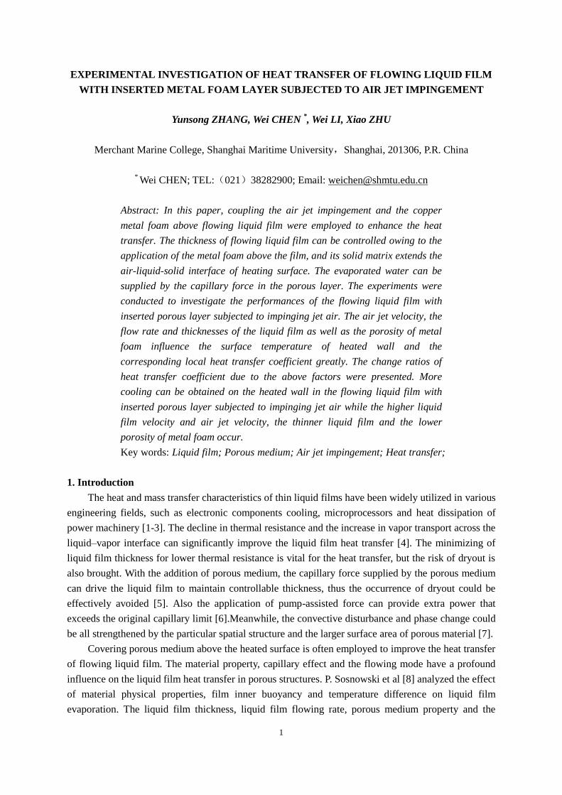
The experimental apparatus was comprised of a
working fluid circulation system, an air supply
system, an adjustable heating system, a test bench
and a data acquirement system, as shown in Fig.1.
During operation, the deionized water served as
working fluid was pumped to the liquid film flow-
path in which the phase change took place within
porous layer and on the outside surface of porous
layer. The thermal insulation was set around the
conducting bar and flow path, thus the less heat loss
occurred from the envelop enclosure of flow path to
the outside. Due to the liquid fluid with the inserted
metal foam, the thickness of liquid fluid layer changed
Figure 1. Schematic diagram of flowing liquid
film with inserted metal foam porous layer
subjected to air jet impingement
3
from δf=0.0005m to δf=0.002m, the flowing liquid layer is considered as a flowing liquid film. The
flow rate of working fluid was controlled and measured through a regulating valve and a rotameter.
Residual water at flow-path exit was recycled to a recycling tank. The generated vapor was dissipated
by jet air and the phase change process continued. The surface of flow path tended to a smooth plate
and the velocity of liquid fluid changed from Vf=0.018m/s to Vf=0.054m/s, thus the friction along flow
path influenced less in tests.
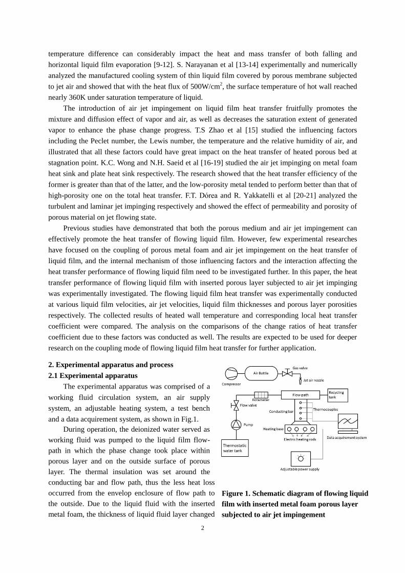
The flow-path was made up of a specially manufactured metal square cavity (0.14×0.04×0.015m),
with the metal foam porous layer embedded on the top groove (0.065×0.023×0.01m), as shown in
Fig.2 (a) and Fig.2 (c). The gap between the porous layer bottom and the heated wall surface was
adjusted using shims at certain thicknesses. Once the distance was fixed, the shim was taken away and
the metal foam was adhered to the surrounding wall to avoid the side flow and to control the thickness
of liquid film when the liquid fluid passed through the flow path. As the insulation cotton was set
around the flow path, less heat was transferred from the side passages of flow path to the outside.
Four testing points, each diameter in 0.001m, depth in 0.01m and separation distance in 0.01m,
were averagely located along the axial direction of the conducting bar that had a diameter of 0.02m, as
shown in Fig.2 (b). These equidistantly distributed testing points were designated for inserting
thermocouples to averagely calculate the heat flux from the heating base to the heated wall surface
using Fourier’s law. Both the conducting bar and the heated wall were made of copper. Four
thermocouples were inserted in the outer surface of thermal insulation cotton around for heat loss
calculation.
2.2 Experimental preparation
(a)
All thermocouples were calibrated within minimized error. Based on the primary test of error, the
uncertainty of the temperature measurement of thermocouples was less than 0.1℃ , while the
Figure 2. (a) Flow-path and conducting bar (b) Specifications of flow-path and
conducting bar (c) Flow-path and metal foam porous layer enwrapped by insulation
(b)
(c)
4
minimum temperature difference of each adjoining thermocouples was 1.5℃ . Therefore the
uncertainty of the heat flux was less than 6.7%.
All thermal contact surfaces were adhered by highly conductive thermal grease (8.5W·m-1
·K-1
) to
keep efficient heat transfer. The temperatures of jet air and the working fluid stored in the thermostatic
tank were remained at 25℃.
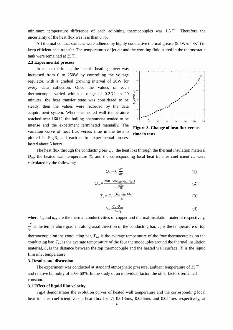
2.3 Experimental process
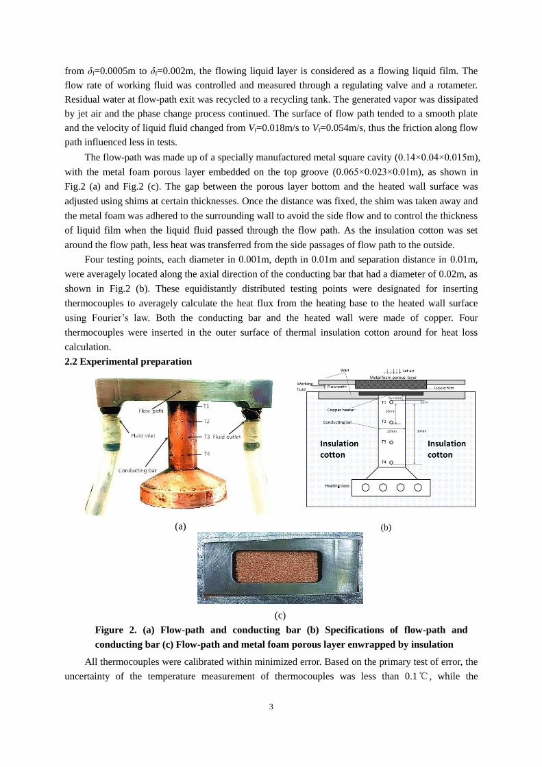
In each experiment, the electric heating power was
increased from 0 to 250W by controlling the voltage
regulator, with a gradual growing interval of 20W for
every data collection. Once the values of each
thermocouple varied within a range of 0.2℃ in 20
minutes, the heat transfer state was considered to be
steady, then the values were recorded by the data
acquirement system. When the heated wall temperature
reached near 160℃, the boiling phenomena tended to be
intense and the experiment terminated manually. The
variation curve of heat flux versus time in the tests is
plotted in Fig.3, and each entire experimental process
lasted about 5 hours.
The heat flux through the conducting bar Qw, the heat loss through the thermal insulation material
Qins, the heated wall temperature Tw and the corresponding local heat transfer coefficient hw were
calculated by the following:
Qw=-kcp
dT
dy (1)
Qins= 2×0.05πkins(Tave-Tins)
ln (160
10)
(2)
Tw = T1-(Qw-Qins)δw
kcp (3)
hw=Qw-Qins
Tw-Tf (4)
where kcp and kins are the thermal conductivities of copper and thermal insulation material respectively,
dT
dy is the temperature gradient along axial direction of the conducting bar, T1 is the temperature of top
thermocouple on the conducting bar, Tave is the average temperature of the four thermocouples on the
conducting bar, Tins is the average temperature of the four thermocouples around the thermal insulation
material, δw is the distance between the top thermocouple and the heated wall surface, Tf is the liquid
film inlet temperature.
3. Results and discussion
The experiment was conducted at standard atmospheric pressure, ambient temperature of 25℃
and relative humidity of 50%-60%. In the study of an individual factor, the other factors remained
constant.
3.1 Effect of liquid film velocity
Fig.4 demonstrates the evolution curves of heated wall temperature and the corresponding local
heat transfer coefficient versus heat flux for Vf=0.018m/s, 0.036m/s and 0.054m/s respectively, at
Figure 3. Change of heat flux versus
time in tests
5
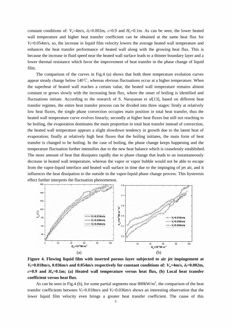
constant conditions of: Va=4m/s, δf=0.002m, ε=0.9 and Hn=0.1m. As can be seen, the lower heated
wall temperature and higher heat transfer coefficient can be obtained at the same heat flux for
Vf=0.054m/s, so, the increase in liquid film velocity lowers the average heated wall temperature and
enhances the heat transfer performance of heated wall along with the growing heat flux. This is
because the increase in fluid speed near the heated wall surface leads to a thinner boundary layer and a
lower thermal resistance which favor the improvement of heat transfer in the phase change of liquid
film.
The comparison of the curves in Fig.4 (a) shows that both three temperature evolution curves
appear steady change below 140℃, whereas obvious fluctuations occur at a higher temperature. When
the superheat of heated wall reaches a certain value, the heated wall temperature remains almost
constant or grows slowly with the increasing heat flux, where the onset of boiling is identified and
fluctuations initiate. According to the research of S. Narayanan et al[13], based on different heat
transfer regimes, the entire heat transfer process can be divided into three stages: firstly at relatively
low heat fluxes, the single phase convection occupies main position in total heat transfer, thus the
heated wall temperature curve evolves linearly; secondly at higher heat fluxes but still not reaching to
be boiling, the evaporation dominates the main proportion in total heat transfer instead of convection,
the heated wall temperature appears a slight slowdown tendency in growth due to the latent heat of
evaporation; finally at relatively high heat fluxes that the boiling initiates, the main form of heat
transfer is changed to be boiling. In the case of boiling, the phase change keeps happening and the
temperature fluctuation further intensifies due to the new heat balance which is ceaselessly established.
The more amount of heat that dissipates rapidly due to phase change that leads to an instantaneously
decrease in heated wall temperature, whereas the vapor or vapor bubble would not be able to escape
from the vapor-liquid interface and heated wall surface in time due to the impinging of jet air, and it
influences the heat dissipation to the outside in the vapor-liquid phase change process. This hysteresis
effect further interprets the fluctuation phenomenon.
(a) (b)
Figure 4. Flowing liquid film with inserted porous layer subjected to air jet impingement at
Vf=0.018m/s, 0.036m/s and 0.054m/s respectively for constant conditions of: Va=4m/s, δf=0.002m,
ε=0.9 and Hn=0.1m; (a) Heated wall temperature versus heat flux, (b) Local heat transfer
coefficient versus heat flux.
As can be seen in Fig.4 (b), for some partial segments near 800kW/m2, the comparison of the heat
transfer coefficients between Vf=0.018m/s and Vf=0.036m/s shows an interesting observation that the
lower liquid film velocity even brings a greater heat transfer coefficient. The cause of this
6
phenomenon is that at relatively high heat fluxes where boiling initiates, the boiling accounts for a
more substantial proportion in total heat transfer at a slower fluid speed than that of at a higher fluid
speed, since lower fluid speed causes more time to be used to heat a unit volume of fluid so that the
phase change process is enhanced. Therefore, the heated wall temperature is declined at the lower flow
velocity of liquid film and the heat transfer coefficient is enhanced by the more effective cooling effect
due to phase change.
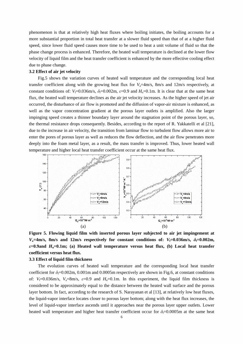
3.2 Effect of air jet velocity
Fig.5 shows the variation curves of heated wall temperature and the corresponding local heat
transfer coefficient along with the growing heat flux for Va=4m/s, 8m/s and 12m/s respectively, at
constant conditions of: Vf=0.036m/s, δf=0.002m, ε=0.9 and Hn=0.1m. It is clear that at the same heat
flux, the heated wall temperature declines as the air jet velocity increases. As the higher speed of jet air
occurred, the disturbance of air flow is promoted and the diffusion of vapor-air mixture is enhanced, as
well as the vapor concentration gradient at the porous layer outlets is amplified. Also the larger
impinging speed creates a thinner boundary layer around the stagnation point of the porous layer, so,
the thermal resistance drops consequently. Besides, according to the report of R. Yakkatelli et al [21],
due to the increase in air velocity, the transition from laminar flow to turbulent flow allows more air to
enter the pores of porous layer as well as reduces the flow deflection, and the air flow penetrates more
deeply into the foam metal layer, as a result, the mass transfer is improved. Thus, lower heated wall
temperature and higher local heat transfer coefficient occur at the same heat flux.
(a) (b)
Figure 5. Flowing liquid film with inserted porous layer subjected to air jet impingement at
Va=4m/s, 8m/s and 12m/s respectively for constant conditions of: Vf=0.036m/s, δf=0.002m,
ε=0.9and Hn=0.1m; (a) Heated wall temperature versus heat flux, (b) Local heat transfer
coefficient versus heat flux.
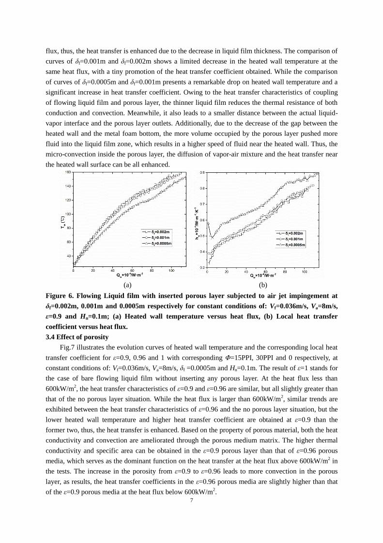
3.3 Effect of liquid film thickness
The evolution curves of heated wall temperature and the corresponding local heat transfer
coefficient for δf=0.002m, 0.001m and 0.0005m respectively are shown in Fig.6, at constant conditions
of: Vf=0.036m/s, Va=8m/s, ε=0.9 and Hn=0.1m. In this experiment, the liquid film thickness is
considered to be approximately equal to the distance between the heated wall surface and the porous
layer bottom. In fact, according to the research of S. Narayanan et al [13], at relatively low heat fluxes,
the liquid-vapor interface locates closer to porous layer bottom; along with the heat flux increases, the
level of liquid-vapor interface ascends until it approaches near the porous layer upper outlets. Lower
heated wall temperature and higher heat transfer coefficient occur for δf=0.0005m at the same heat
7
flux, thus, the heat transfer is enhanced due to the decrease in liquid film thickness. The comparison of
curves of δf=0.001m and δf=0.002m shows a limited decrease in the heated wall temperature at the
same heat flux, with a tiny promotion of the heat transfer coefficient obtained. While the comparison
of curves of δf=0.0005m and δf=0.001m presents a remarkable drop on heated wall temperature and a
significant increase in heat transfer coefficient. Owing to the heat transfer characteristics of coupling
of flowing liquid film and porous layer, the thinner liquid film reduces the thermal resistance of both
conduction and convection. Meanwhile, it also leads to a smaller distance between the actual liquid-
vapor interface and the porous layer outlets. Additionally, due to the decrease of the gap between the
heated wall and the metal foam bottom, the more volume occupied by the porous layer pushed more
fluid into the liquid film zone, which results in a higher speed of fluid near the heated wall. Thus, the
micro-convection inside the porous layer, the diffusion of vapor-air mixture and the heat transfer near
the heated wall surface can be all enhanced.
(a) (b)
Figure 6. Flowing Liquid film with inserted porous layer subjected to air jet impingement at
δf=0.002m, 0.001m and 0.0005m respectively for constant conditions of: Vf=0.036m/s, Va=8m/s,
ε=0.9 and Hn=0.1m; (a) Heated wall temperature versus heat flux, (b) Local heat transfer
coefficient versus heat flux.
3.4 Effect of porosity
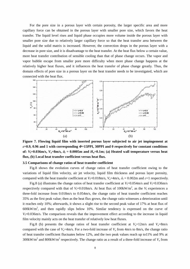
Fig.7 illustrates the evolution curves of heated wall temperature and the corresponding local heat
transfer coefficient for ε=0.9, 0.96 and 1 with corresponding Φ=15PPI, 30PPI and 0 respectively, at
constant conditions of: Vf=0.036m/s, Va=8m/s, δf =0.0005m and Hn=0.1m. The result of ε=1 stands for
the case of bare flowing liquid film without inserting any porous layer. At the heat flux less than
600kW/m2, the heat transfer characteristics of ε=0.9 and ε=0.96 are similar, but all slightly greater than
that of the no porous layer situation. While the heat flux is larger than 600kW/m2, similar trends are
exhibited between the heat transfer characteristics of ε=0.96 and the no porous layer situation, but the
lower heated wall temperature and higher heat transfer coefficient are obtained at ε=0.9 than the
former two, thus, the heat transfer is enhanced. Based on the property of porous material, both the heat
conductivity and convection are ameliorated through the porous medium matrix. The higher thermal
conductivity and specific area can be obtained in the ε=0.9 porous layer than that of ε=0.96 porous
media, which serves as the dominant function on the heat transfer at the heat flux above 600kW/m2 in
the tests. The increase in the porosity from ε=0.9 to ε=0.96 leads to more convection in the porous
layer, as results, the heat transfer coefficients in the ε=0.96 porous media are slightly higher than that
of the ε=0.9 porous media at the heat flux below 600kW/m2.
8
For the pore size in a porous layer with certain porosity, the larger specific area and more
capillary force can be obtained in the porous layer with smaller pore size, which favors the heat
transfer. The liquid level rises and liquid phase occupies more volume inside the porous layer with
smaller pore size due to relatively larger capillary force so that the heat transfer area between the
liquid and the solid matrix is increased. However, the convection drops in the porous layer with a
decrease in pore size, and it is disadvantage to the heat transfer. At the heat flux below a certain value,
more heat transfer contribution of sensible cooling than that of phase change occurs. The vapor and
vapor bubble escape from smaller pore more difficulty when more phase change happens at the
relatively higher heat fluxes, and it influences the heat transfer of phase change greatly. Thus, the
domain effects of pore size in a porous layer on the heat transfer needs to be investigated, which are
connected with the heat flux.
(a) (b)
Figure 7. Flowing liquid film with inserted porous layer subjected to air jet impingement at
ε=0.9, 0.96 and 1 with corresponding Φ=15PPI, 30PPI and 0 respectively for constant conditions
of: Vf=0.036m/s, Va=8m/s, δf = 0.0005m and Hn=0.1m; (a) Heated wall temperature versus heat
flux, (b) Local heat transfer coefficient versus heat flux.
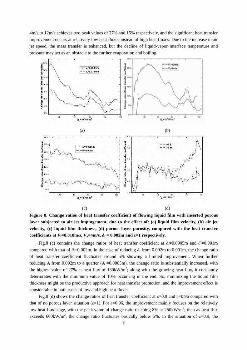
3.5 Comparisons of change ratios of heat transfer coefficient
Fig.8 shows the evolution curves of change ratios of heat transfer coefficient owing to the
variations of liquid film velocity, air jet velocity, liquid film thickness and porous layer porosity,
compared with the heat transfer coefficient at Vf=0.018m/s, Va=4m/s, δf = 0.002m and ε=1 respectively.
Fig.8 (a) illustrates the change ratios of heat transfer coefficient at Vf=0.054m/s and Vf=0.036m/s
respectively compared with that of Vf=0.018m/s. At heat flux of 100kW/m2, as the Vf experiences a
three-fold increase from 0.018m/s to 0.054m/s, the change ratio of heat transfer coefficient reaches
35% as the first peak value; then as the heat flux grows, the change ratio witnesses a deterioration until
it reaches only 10%; afterwards, it shows a slight rise to the second peak value of 17% at heat flux of
600kW/m2, and then rapidly slips below 10%. Similar tendency is expressed on the curve of
Vf=0.036m/s. The comparison reveals that the improvement effect according to the increase in liquid
film velocity mainly acts on the heat transfer of relatively low heat fluxes.
Fig.8 (b) presents the change ratios of heat transfer coefficient at Va=12m/s and Va=8m/s
compared with the case of Va=4m/s. For a two-fold increase of Va from 4m/s to 8m/s, the change ratio
of heat transfer coefficient fluctuates below 12%, and the two peak values reach up to11% and 9% at
300kW/m2 and 800kW/m
2 respectively. The change ratio as a result of a three-fold increase of Va from
9
4m/s to 12m/s achieves two peak values of 27% and 15% respectively, and the significant heat transfer
improvement occurs at relatively low heat fluxes instead of high heat fluxes. Due to the increase in air
jet speed, the mass transfer is enhanced, but the decline of liquid-vapor interface temperature and
pressure may act as an obstacle to the further evaporation and boiling.
(a) (b)
(c) (d)
Figure 8. Change ratios of heat transfer coefficient of flowing liquid film with inserted porous
layer subjected to air jet impingement, due to the effect of: (a) liquid film velocity, (b) air jet
velocity, (c) liquid film thickness, (d) porous layer porosity, compared with the heat transfer
coefficients at Vf=0.018m/s, Va=4m/s, δf = 0.002m and ε=1 respectively.
Fig.8 (c) contains the change ratios of heat transfer coefficient at δf=0.0005m and δf=0.001m
compared with that of δf=0.002m. In the case of reducing δf from 0.002m to 0.001m, the change ratio
of heat transfer coefficient fluctuates around 5% showing a limited improvement. When further
reducing δf from 0.002m to a quarter (δf =0.0005m), the change ratio is substantially increased, with
the highest value of 27% at heat flux of 180kW/m2; along with the growing heat flux, it constantly
deteriorates with the minimum value of 10% occurring in the end. So, minimizing the liquid film
thickness might be the productive approach for heat transfer promotion, and the improvement effect is
considerable in both cases of low and high heat fluxes.
Fig.8 (d) shows the change ratios of heat transfer coefficient at ε=0.9 and ε=0.96 compared with
that of no porous layer situation (ε=1). For ε=0.96, the improvement mainly focuses on the relatively
low heat flux stage, with the peak value of change ratio reaching 8% at 250kW/m2; then as heat flux
exceeds 600kW/m2, the change ratio fluctuates basically below 5%. In the situation of ε=0.9, the
10
change ratio appears a slight wave below 10% at the heat flux less than 600kW/m2, but then is greatly
enhanced until the peak value of 19% at 950kW/m2. Based on the phenomenon, to some extent the
lower porosity brings greater heat transfer coefficient, but the improvement effect on heat transfer
mainly plays a role in the case of high heat fluxes.
4. Conclusion
The experiment of heat transfer of flowing liquid film with inserted metal foam porous layer
subjected to air jet impingement has been conducted. The factors of liquid film velocity, air jet velocity,
liquid film thickness and material porosity have impact on heat transfer performance of flowing liquid
film to different degrees at various heat fluxes. The comparisons of the change ratios of heat transfer
coefficient due to those factors reveal the mechanism of heat transfer in the process of flowing liquid
film coupling with jet air and porous layer.
The summary of the major results can be concluded as follows:
1) The increase in liquid film velocity enhances the cooling performance, and for a three-fold
increase from 0.018m/s to 0.054m/s, the change ratio nearly reaches up to 35% and 15%
respectively at relatively low and high heat fluxes, thus the improvement effect of liquid film
velocity on heat transfer coefficient is focused on the stage of relatively low heat fluxes.
2) The increase in air jet velocity can improve the heat transfer performance, and at relatively low
heat fluxes, the maximum change ratio according to a two-fold increase of air jet velocity is only
12% whilst for a three-fold air speed increase it can be up to 27%; at relatively high heat fluxes,
both the change ratios due to the two-fold and three-fold increase of air jet velocity are not
significant. Thus, the increase in air jet velocity mainly improves the heat transfer coefficient in
the case of relatively low heat fluxes, and the enhancement at relatively high heat fluxes situation
is restricted.
3) The decrease in liquid film thickness increases the heat transfer coefficient, and further reducing
the thickness up to a quarter of the original value leads to a more substantial growth in heat
transfer coefficient, and the change ratio can be up to 10%-27%. The improvement effect of
minimizing the liquid film thickness on heat transfer coefficient can act on both occasions of low
and high heat fluxes.
4) Compared with bare flowing liquid film, inserting porous layer can improve the heat transfer
performance of flowing liquid film. The decrease of porosity from 0.96 to 0.9 leads to a increase
in the heat transfer coefficient when the heat fluxes are above a certain value, and the change ratio
of heat transfer coefficient for porosity of 0.9 can amount up to 19% while that for porosity of 0.96
only remains below 5%. The variations of thermal conductivity, specific area and convection in
the porous layer are related to its porosity, which influence the heat transfer coefficients more
greatly with the increase in the heat flux.
5) Based on the results above, by strengthening the control on these factors, the approach on deeper
optimization of the heat transfer performance in the applications of cooling system promotion is
available.
Acknowledgements
The current work is financially supported by the National Natural Science Foundation of China
(No.51276107), the Innovation Program of Shanghai Municipal Education Commission (14ZZ142)
and the Ministry of Transport Application Foundation Project (2013319810150).
11
Nomenclature
D diameter, [m]
Hn nozzle height, [m]
hw local heat transfer coefficient of heated wall, [W·m-2
·K-1
]
kcp thermal conductivity of copper, [W·m-1
·K-1
]
kins thermal conductivity of insulation material, [W·m-1
·K-1
]
Qins heat loss through thermal insulation material, [W·m-2
]
Qw heat flux through the heated wall, [W·m-2
]
Tw temperature of heated wall, [K/℃]
Tf temperature of liquid film, [K/℃]
Va air jet velocity, [m/s]
Vf liquid film velocity, [m/s]
y axial direction
Greek symbols
δf thickness of liquid film, [m]
δw distance between the top thermocouple and heated wall surface, [m]
ε porosity of metal foam
Φ pore density, [PPI]
Subscripts
a air
cp copper
f liquid film
ins insulation material
m metal foam
n nozzle
w heated wall
References
[1]Wang, H.,Garimella, S.V., et al.,An analytical solution for the total heat transfer in the thin-film
region of an evaporating meniscus, International Journal of Heat and Mass Transfer, 51(2008), pp.
6317–6322.
[2]Souza A G U D, Jr J R B. Spray cooling of plain and copper-foam enhanced surfaces[J].
Experimental Thermal & Fluid Science, 2012, 39:198-206.
[3]Crepinsek M, Park C. Experimental analysis of pump-assisted and capillary-driven dual-
evaporators two-phase cooling loop[J]. Applied Thermal Engineering, 2012, 38(1):133-142.
[4]Zhou, Y.Y., Yu, J.L.,et al., A study on flow and heat transfer characteristics for saturated falling-film
evaporation of liquid oxygen in a vertical channel, International Journal of Heat and Mass Transfer,
55(2012), pp. 7218-7222.
[5]Qu, W., Ma, T.Z.,et al., Effects of radius and heat transfer on the profile of evaporating thin liquid
film and meniscus in capillary tubes, International Journal of Heat and Mass Transfer,45( 2002),
pp.1879-1887.
12
[6]Shirazy, M.R.S.,Fréchette, L.G., Capillary and wetting properties of copper metal foams in the
presence of evaporation and sintered walls, International Journal of Heat and Mass Transfer, 58(2013),
pp.282-291.
[7]Lee, S.,Köroğlu, B., et al., Experimental investigation of capillary assisted solution wetting and
heat transfer using a micro-scale, porous-layer coating on horizontal-tube, falling-film heat exchanger,
International Journal of Refrigeration, 35(2012), pp.1176-1187.
[8]Sosnowski, P., Petronio, A., et al.,Numerical model for thin liquid film with evaporation and
condensation on solid surfaces in systems with conjugated heat transfer, International Journal of Heat
and Mass Transfer, 66(2013), pp. 382-395.
[9]Shahzad, M.W., Myat, A., et al., Bubble-assisted film evaporation correlation for saline water at
sub-atmospheric pressures in horizontal-tube evaporator, Applied Thermal Engineering, 50(2013), pp.
670-676.
[10]Nasr, A., Al-Ghamdi, A.S. Numerical study of evaporation of falling liquid film on one of two
vertical plates covered with a thin porous layer by free convection, International Journal of Thermal
Sciences, 112(2017), pp. 335-344.
[11]Terzi, A., Foudhil,W. S., et al., Liquid film evaporation inside an inclined channel: Effect of the
presence of a porous layer, International Journal of Thermal Sciences, 109(2016 ), pp. 136-147.
[12]Leu, J.S., Jang, J.Y., et al., Heat and mass transfer for liquid film evaporation along a vertical plate
covered with a thin porous layer, International Journal of Heat and Mass Transfer, 49(2006), pp. 1937-
1945.
[13]Narayanan, S., Fedorov, A.G., et al., Heat and mass transfer during evaporation of thin liquid films
confined by nanoporous membranes subjected to air jet impingement, International Journal of Heat
and Mass Transfer, 58(2013), pp. 300-311.
[14]Narayanan, S., Fedorov, A.G., On-chip thermal management of hotspots using a perspiration
nanopatch, Journal of Micromechanics and Microengineering, 7(2010), pp. 10.
[15]Zhao, T.S., Coupled heat and mass transfer of a stagnation point flow in a heated porous bed with
liquid film evaporation, International Journal of Heat and Mass Transfer, (1999), pp. 861-872.
[16]Wong, K.C., Indran, S., Impingement heat transfer of a plate fin heat sink with fillet profile,
International Journal of Heat and Mass Transfer, 65(2013), pp. 1-9.
[17]Wong, K.C., Saeid, N.H., Numerical study of mixed convection on jet impingement cooling in a
horizontal porous layer-using Brinkman-extended Darcy model, International Journal of Thermal
Sciences,48(2009), pp. 96-104.
[18]Wong, K.C., Saeid, N.H., Numerical study of mixed convection on jet impingement cooling in an
open cavity filled with porous medium, International Communications in Heat and Mass Transfer,
36(2009), pp. 155-160.
[19]Wong, K.C., Thermal analysis of a metal foam subject to jet impingement, International
Communications in Heat and Mass Transfer, 39(2012),pp. 960–965.
[20]Dórea, F.T., de Lemos, M.J.S., Simulation of laminar impinging jet on a porous medium with a
thermal non-equilibrium model, International Journal of Heat and Mass Transfer, 53(2010), pp. 5089-
5101.
[21] Yakkatelli, R., Wu, Q.H., et al., A visualization study of the flow dynamics of a single round jet
impinging on porous media, Experimental Thermal and Fluid Science, 34(2010), pp. 1008–1015.