Embed Size (px)
Citation preview

Scientific Research and Essays Vol. 5 (24), pp. 3955-3966, 18 December, 2010 Available online at http://www.academicjournals.org/SRE ISSN 1992-2248 ©2010 Academic Journals Full Length Research Paper
Experimental investigation of using ground source heat pump system for snow melting on pavements and
bridge decks
Asim Balbay1* and Mehmet Esen2
1Department of Mechanical Engineering, Faculty of Engineering and Architecture, Siirt University, 56100, Siirt, Turkey. 2Department of Mechanical Education, Faculty of Technical Education, Firat University, 23119, Elazi�, Turkey.
Accepted 5 October, 2010
Melting snow with a hydronic heating system can eliminate the need for snow removal by chemical or mechanical means and provide greater safety for pedestrians and vehicles. So, a preliminary practical feasibility study of using a ground source heat pump (GSHP) system for snow melting on pavements and bridge decks had been performed for the first time in Turkey on the basis of a university study. The objective of this paper is to investigate the practicability of a GSHP system consisting of the vertical type single U-borehole heat exchangers with different lengths for snow melting on pavements and bridge decks. For this purpose, the vertical drilling of the borehole was performed for three different depths (30, 60, and 90 m) in Elazig, Turkey and U-tube heat exchangers were inserted into the corresponding boreholes. Experiments in winter season of 2006-2007 were carried out for melting snow on surfaces of the prototypes of bridge-slab (BS) and pavement-slab (PS) constructed for the experimental study. The effect of the depth of borehole coupled to heat exchanger on the snow melting system performance was experimentally investigated. This way, the snow accumulation on the surfaces of bridge-slab (BS) and pavement-slab (PS) were efficiently heated and thus melted. Development of the model is described in a companion paper. Key words: Snow/ice melting, ground source heat pump, bridge, pavement.
INTRODUCTION A nice and clear road in the winter is not only a convenience; it can also enhance safety and prevent property damage. Travel is hazardous in the late fall, *Corresponding author. E-mail: [email protected]. Tel: +90-484-223 12 24/1223. Fax: +90-484-223 20 98. Abbreviations: BHE, Borehole heat exchanger; BS, bridge-slab; BS-30, bridge-slab at worked for 30 m borehole; BS-60, bridge-slab at worked for 60 m borehole; BS-90, bridge-slab at worked for 90 m borehole; COP, coefficient of performance for GSHP (-); GHE, ground heat exchanger; GSHP, ground source heat pump; HP, heat pump; PS, pavement-slab; PS-30, pavement-slab at worked for 30 m borehole; PS-60, pavement-slab at worked for 60 m borehole; PS-90, pavement-slab at worked for 90 m borehole.
winter, and early spring, during periods of snow, sleet and freezing rain. Preventing snow accumulation and ice formation on roads, especially on some critical sections including bridges, emergencies of hospital and ramps etc. is important to improve transportation safety at winter conditions. Perhaps the greatest danger along this line is the frequent occurrence of preferential icing of bridges, where bridge decks become icy and slick while adjacent roadways remain clear. The reason is that bridges are usually elevated and exposed to the ambient air, and therefore tend to cool more quickly than roads, which are warmed by the earth underneath (Liu, 2005; Spitler, 2000; Chiasson and Spitler, 2000; Liu and Spitler, 2004; Liu et al., 2003). By far, the most frequent responses to bridge deck icing are the applications of salt and/or sand or other gritty material. Salt applied to a bridge deck prior to icing can prevent preferential icing. Timing of the

3956 Sci. Res. Essays application of salt and sand is often problematic. Ice will not be melted by the most popularly used salt (sodium chloride) if the temperature falls below 25°F (-3.9°C). Furthermore, salt is corrosive and eventually penetrates down to the reinforcing steel. When it corrodes, the bridge deck life is reduced. Some alternative, non-corrosive substances are available, but they are significantly more expensive. Also, road salt applications can keep roads free of ice for safe winter travel; however this practice comes at a cost to the infrastructure and the environment, especially in urban areas with high road densities. Much of the rock salt applied to the roads is dissolved in the melting snow and ice. The salt containing water runs off into streams, lakes or storm sewers or infiltrates into the soil eventually reaching the groundwater affecting the chemistry and biota in the soil and water (Novotny et al., 2008).
Melting snow and ice can be less expensive and more effective and environmentally friendly than using mechanical and chemical alternatives. Snow melting systems are installed in a wide range of applications, such as sidewalks, driveways, steps, toll plazas, and bridges, to eliminate the need for snow removal and increase safety (Liu et al., 2007; Lund, 2000; Wang et al., 2008; Wang and Chen, 2009; Nagai et al., 2009). Recently, an alternative method to applying salting, sanding and using mechanical devices is to use automatically controlled hydronic and electrical snow melting systems to prevent ice formation and melting snow on critical surfaces (Espin, 2003; Liu and Spitler, 2004). Hydronic heating systems that circulate a heated fluid through a pipe network embedded in a bridge deck or roadway may be used to eliminate or reduce dangerous driving conditions caused by snow and ice. Instead of salting, sanding and using mechanical devices such systems can reduce the rate of corrosion drastically in bridge decks and so extend the life of road. The pipe network consists of number of circuits, which are usually laid in a serpentine configuration. The pipe material is usually either cross-linked or high-density polyethylene. Typical pipe spacing ranges from 6 to 12 in (150 to 300 mm) at a depth of 2 to 3 in (50 to 75 mm). Nominal pipe diameters are commonly ¾ or 1 inch (20 or 25 mm) (Chapman, 1999; Ramsey et al., 1999; Rees et al., 2002; Hamada et al., 2007). Also, there are other alternative methods for snow/ice melting: (1) Using exhausted heat of vehicles (Suda et al., 2001); (2) Using infrared systems [Tumidajski et al., 2003; Hayden, 1998], where heat is generated by overhead high intensity radiant panels. Because of the relatively large power consumption required by electric and infrared systems, hydronic systems are perhaps the most practical type for large applications such as roadways. In typical hydronic system applications, a gas-fired or electric boiler is generally used to heat the working fluid. However, snow melting systems consume much bigger amount of thermal energy than most people think due to a large
amount of heat loss to the ambient in addition to needed heat for melting snow. From energy conversation and CO2 reduction as well as saving running expense point of view, heat pump technologies have recently been applied into the snow melting systems. Some kinds of natural heat resources such as air (Sawase et al., 1989), ground water and ground heat source become the candidates of the heat source of the heat pump. In particular, ground heat source has been recognized as the most promising potential on account of its universal existence and long term indubitability (Esen et al., 2007, 2006; Inalli and Esen, 2004).
A half of the Turkey land has been considered as the heavy snowfall area in winter and more than twenty million people live there. Snow precipitation in a day sometimes reaches over 600 mm high and people expend a considerable amount of work and time remove accumulated snow and to maintain the daily activities. Snow/ice melting by geothermal water and ground-source heat pump is used in several countries, including Iceland, Japan, and United States for several decades (Chiasson et al., 2000; Takahashi and Uemoto, 2004; Boyd, 2003; Lund and Freeston, 2001; Zwaryez, 2002). For the work described here, we plan to use a ground-source heat pump (GSHP) system as an energy efficient means to provide the heating requirement of snow/ice melting process. This system makes use of hydronic heating in the bridge deck and pavement, with the heat source being a ground-source heat pump. The system studied in this work for snow melting consists of ground borehole heat exchangers with three different depths (30, 60 and 90 m), a water-to-water heat pump and heating pipes buried under the bridge-slab (BS) and pavement-slab (PS). The experimental snow/ice melting set-up, described in this study is constructed and tested for the first time on the basis of a university study performed in the country (Balbay, 2008). In this study, the effect of the depth of borehole coupled to heat exchanger on the snow melting system performance was experimentally investigated. MATERIALS AND METHODS Materials A schematic view of the experimental set up is shown in Figure 1. It mainly consists of a vertical GSHP system, two prototype slabs (bridge-slab (BS) and pavement-slab (PS), a circulation pump, and `pipe circuits. In this study, vertical drilling of borehole for the GSHP unit was performed for three different depths (30, 60 and 90 m) in Elazig, Turkey. Each consists of a high density polyethylene tube of 40 mm diameter. The main characteristic of high density polyethylene tube is shown in Table 1. The borehole diameter is 150 mm. The horizontal distances between the boreholes are 3.4 and 2 m, respectively (see Figure 2). The vertical type single U-borehole heat exchangers were linked with a HP unit which was placed in a house and manufactured with the national facilities. U-pipe heat exchangers were buried into the marl type ground (thermal conductivity, λ =1.70 W/mK). Completing a closed loop

Balbay and Esen 3957
Figure 1. The schematic view of experimental set-up.
borehole requires placing material- grout or fill- in the space between the heat exchanger pipe and the borehole wall. Two classes of material are generally used: Grout and fill. Grout is a high solid fluid mixture of cement or bentonite of a consistency that can be forced through a pipe and placed as required. The reason fill is used is to achieve greater heat transfer than grout can provide. In this study, bentonite is used as a grout material for boreholes.
The heat transfer from ground to the HP or from the HP to ground is maintained with the fluid or water-antifreeze solution (25% by weight) circulated through the BHEs. The fluid transfers its heat to refrigerant fluid in the evaporator (the water-antifreeze solution to refrigerant heat exchanger). The refrigerant, which flows
through other closed loop in the HP, evaporates by absorbing heat from the water-antifreeze solution circulated through the evaporator and then enters the hermetic compressor. The water-antifreeze solution in the BHEs loop collects heat from the ground and transfers that heat to the HP. After the heat exchange fluid absorbs heat from the ground, the closed loop BHEs circulates the heat exchange fluid through pipes.
The prototype concrete slabs for snow/ice melting on their top surfaces were constructed using a wooden frame, which subsequently remain attached to the slab. The snow/ice on surfaces of the bridge-slab (BS) and pavement-slab (PS) were heated and melted by the GSHP. The test slabs are rectangular

3958 Sci. Res. Essays
Table 1. Main characteristics of U-pipe SDR 11. External diameter 40 mm Internal diameter 35.2 mm Density 0.96 g/cm3
Melting temperature 130°C Working temperature 90°C Peak temperature (momentary) 125°C
Thermal conductivity ( pλ ) 0.4 W/(mK)
Thermal resistance (Rp) 0.0815 (K/(W/m) Coefficient of linear expansion 0.17 mm/(mK)
with a plan area of 1.7 by 1.2 m and a thickness 0.2 m. The slabs have been insulated on all four sides to minimize edge losses. The serpentine pipe configuration is used for both slabs (BS, PS) as shown in Figure 3. Eight parallel lines of pipes were embedded in each frame evenly spaced in the direction of length as shown Figure 3. The specification for the pipe material used in BS and PS is Polyethylene PX-b. The distance between the pipes is 20 cm. The pipe used has an outer diameter of 16 mm and wall thickness of 2.4 mm.
To allow for measurement of the circulating water-antifreeze solution and ground temperature, a number of T-type thermocouples were used. The temperature measurement points of the ground and slab sections are shown in Figures 2 and 3, respectively. The ambient and indoor air temperatures were measured with thermometers. Various water-antifreeze solution flow rates as 0.43, 0.40 and 0.36 L/s are used in experiments for borehole depths of 30, 60 and 90 m. The rated accuracy of the flowmeter is ±0.5% of the reading.
Generally, the operation of a HP used in this application would be controlled with a thermostat, perhaps with a temperature sensor mounted in the BS and PS. In this study, Devireg 850 system is used to keep BS and PS areas free of ice and snow (Figure 4). The Devireg 850 is fully automatic and operated digitally by means of the intelligent sensors located in the heated terrain. Every sensor measures both temperature and moisture, and the system turns the heating elements on and off on the basis of these readings. The location of sensor/tube is crucial for the system’s operation. As a result, we need to adhere to the guidelines when positioning the sensor (Balbay, 2008; Devireg 850, 2008).
An important issue is the accuracy of the measured data as well as the results obtained by experimental studies. Uncertainty is a measure of the “goodness” of a result. Without such a measure, it is impossible to judge the fitness of the value as a basis for making decisions relating to health, safety, commerce or scientific excellence. The uncertainty analysis of the various calculated parameters are estimated according to Holman [Holman, 2001]. In the present study, pressures, temperatures, solar radiation, power consumption and velocity of air were measured with aforementioned instruments. The uncertainties arising in calculating a result due to several independent variables is given by:
2/12n
n
22
2
21
1R ])w
xR
(...)wxR
()wxR
[(w∂∂++
∂∂+
∂∂= (1)
where R = is a given function; wR = total uncertainty; x1, x2, . . ., xn = independent variables; w1, w2, . . ., wn = uncertainty in the independent variables. The total uncertainties of the measurements are estimated to be ±2.52% for the water- antifreeze temperatures and refrigerant temperatures, ±2.26% for the ground temperatures,
±2.17% for the slabs temperatures, ±2.58% for mass flow rates, ±2.37% for pressures, ±3.95% for power inputs to the compressor and circulating pumps as well as ±2.83% for electric currents. The overall uncertainty for COP calculations was found to be ±3.68%. The uncertainty of COP is small enough. Uncertainty in reading values of the table is assumed to be ±0.20%. Methods
The heat extracted from BS or PS, Q� is calculated by the following equation:
)TT(CmQ o,wai,wawa,pwa −= �� (2)
The power input to the compressor cW� , the evaporator’s water-
antifreeze circulating pump epW� and the condenser’s water-
antifreeze circulating pump cpW� are calculated using Equations 3
to 5, respectively:
ϕ= CosUIW ccc� (3)
ϕ= CosUIW epepep� (4)
ϕ= CosUIW cpcpcp� (5)
The COP for the GSHP is calculated by:
cpepc WWW
QCOP
���
�
++= (6)
The water-antifreeze solution flow rate passing BHE and BS or PS is set to 0.36 and 0.056 L/s, respectively as an optimum flow rate throughout the experiments. RESULTS The experimental COP result is given Figure 5 for daily variation. The daily mean values, COP of the GSHP system is calculated as 1.99, 2.66 and 3.05 for borehole depths of 30, 60 and 90 m, respectively. The COP increases with increasing the borehole depth of GSHP.
Figure 6 depicts the variation of borehole ground temperature at different depths and ambient temperature (Ta) during the six-day heating period (10.11.2006-15.11.2006). The numbers (1, 2 …8) in Figure 6 are corresponding to the temperature measurement points in Figure 2. The GSHP system is worked for 30 m borehole at first day. After the first day, the system is not worked, and after the free one day again has been worked for 60 m borehole. Before the last day (15.11.2006), the system is not worked. After the free day, the system is again worked for 90 m borehole. In these states, ground

Balbay and Esen 3959
Figure 2. Schematic view of the boreholes.
Figure 3. Schematic view of the temperature measurement points for both slabs (BS, PS).

3960 Sci. Res. Essays
Figure 4. Temperature sensor of Devireg 850 embedded in slab.
0
0.5
1
1.5
2
2.5
3
3.5
4
4.5
5
9:00
9:30
10:0
0
10:3
0
11:0
0
11:3
0
12:0
0
12:3
0
13:0
0
13:3
0
14:0
0
14:3
0
15:0
0
15:3
0
16:0
0
CO
P
Time
30 m 60 m 90 m
Figure 5. The daily variation of COP for three different borehole depths.

Balbay and Esen 3961
0
5
10
15
20
25
01:0
0
05:0
0
09:0
0
13:0
0
17:0
0
21:0
0
01:0
0
05:0
0
09:0
0
13:0
0
17:0
0
21:0
0
01:0
0
05:0
0
09:0
0
13:0
0
17:0
0
21:0
0
01:0
0
05:0
0
09:0
0
13:0
0
17:0
0
21:0
0
01:0
0
05:0
0
09:0
0
13:0
0
17:0
0
21:0
0
01:0
0
05:0
0
09:0
0
13:0
0
Time
Tem
pera
ture
(o C)
1 2 3 4 5 6 7 and 8 Ta
Tem
pera
ture
(°C
)
Figure 6. The six days variations of ground temperatures from November 10 to 15, 2006.
temperatures with different depths are shown detailed in Figure 6. In 30 m borehole state, only one measurement had been done. The minimum ground temperature falls into 11°C (dot 1). In 60 m borehole state, two measurements have been done. The minimum ground temperatures fall into 12°C (dot 2) and 13.43°C (dot 3). In 90 m borehole state, three measurements have been done. The minimum ground temperatures fall into 13.15°C (dot 4), 14.22°C (dot 5) and 15°C (dot 6). The values of Tg (dots 7 and 8) and Ta approach each other during the heating season. It can be attributed to the effect of increasing solar radiation near the ground surface.
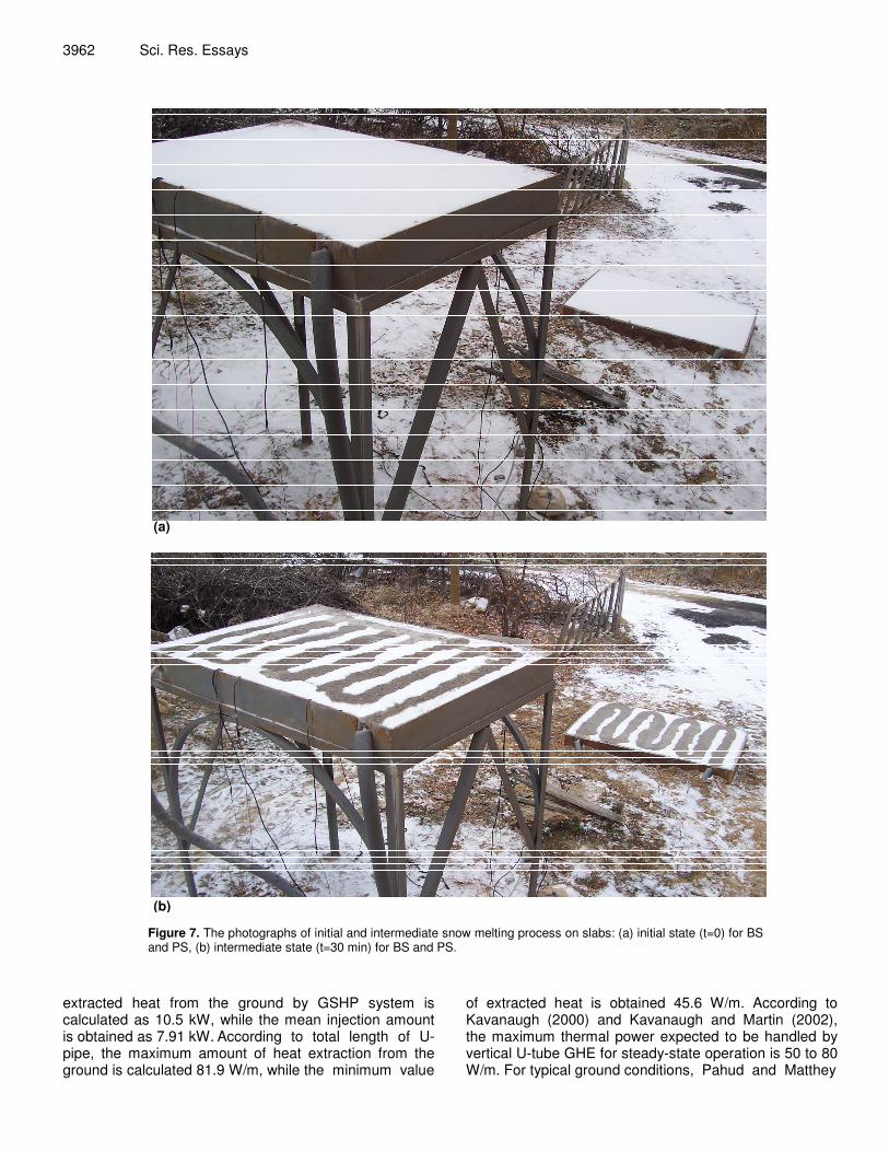
During the experiments, the initial state (t=0) and intermediate state (t = 30 min.) snow melting process’ photographs of BS and PS situations are presented in Figures 7a and b. The pictures showing “stripes” of snow on a heated bridge and pavement surfaces are seen in the figures.
Figure 8 depicts the variation in temperatures in the 7 cm below from upper surfaces in BS and PS for three different borehole depths (30, 60 and 90 m). The mean difference between BS30 and PS30 values is obtained as 3.56°C. The mean difference between BS60 and PS60 values is obtained as 3.68°C. The mean difference between BS90 and PS90 values is obtained as 3.79°C. The air temperature is measured between -8 and -6°C.
Figure 9 shows the variation of the top surface temperatures of BS and PS as well as ambient temperature for 30 m borehole. The average values of BS30 and PS30 surface temperatures are obtained as -2.73 and -1.12°C, respectively. The mean ambient temperature during the experiments is measured as -7.53°C.
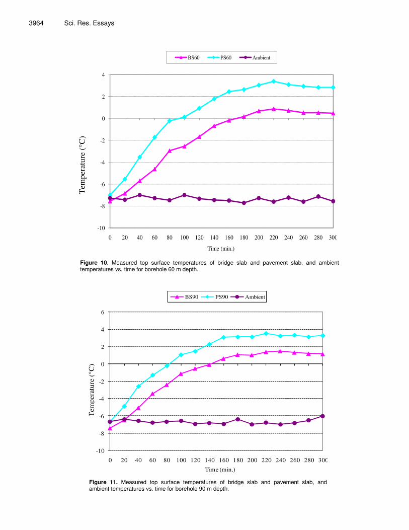
Figure 10 shows the variation of the top surface temperatures of BS and PS as well as ambient temperature for 60 m borehole. The average values of BS60 and PS60 surface temperatures are obtained as -1.79 and 0.5°C, respectively. The mean ambient temperature during the experiments is measured as -7.3°C.
Figure 11 shows the variation of the top surface temperatures of BS and PS as well as ambient temperature for 90 m borehole. The average values of BS90 and PS90 surface temperatures are obtained as -1.07 and 0.94°C, respectively. The mean ambient temperature during the experiments is measured as -6.68°C.
Finally, in case of using boreholes, increasing of average surface temperature in BS was obtained as approximately 0.4°C for each depth of 30 m while increasing of average surface temperature in PS was obtained as approximately 0.5°C for each depth of 30 m.
During the experiment, the maximum amount of
3962 Sci. Res. Essays
(a)
(b) Figure 7. The photographs of initial and intermediate snow melting process on slabs: (a) initial state (t=0) for BS and PS, (b) intermediate state (t=30 min) for BS and PS.
extracted heat from the ground by GSHP system is calculated as 10.5 kW, while the mean injection amount is obtained as 7.91 kW. According to total length of U-pipe, the maximum amount of heat extraction from the ground is calculated 81.9 W/m, while the minimum value
of extracted heat is obtained 45.6 W/m. According to Kavanaugh (2000) and Kavanaugh and Martin (2002), the maximum thermal power expected to be handled by vertical U-tube GHE for steady-state operation is 50 to 80 W/m. For typical ground conditions, Pahud and Matthey

Balbay and Esen 3963
-10
-8
-6
-4
-2
0
2
4
6
8
10
12
0 20 40 60 80 100 120 140 160 180 200 220 240 260 280 300
Time (min.)
Tem
pera
ture
(o C)
BS- 30 PS-30 BS-60 PS-60 BS-90 PS-90
Tem
pera
ture
(°C
)
Figure 8. The slab inner temperatures vs. time for three different borehole depths.
-10
-8
-6
-4
-2
0
2
4
0 20 40 60 80 100 120 140 160 180 200 220 240 260 280 300
Time (min.)
Tem
pera
ture
( o C
)
BS30 PS30 Ambient
Tem
pera
ture
(°C
)
Figure 9. Measured top surface temperatures of bridge slab and pavement slab, and ambient temperatures vs. time for borehole depth 30 m.
3964 Sci. Res. Essays
-10
-8
-6
-4
-2
0
2
4
0 20 40 60 80 100 120 140 160 180 200 220 240 260 280 300
Tem
pera
ture
( o C
)
Time (min.)
BS60 PS60 Ambient
Tem
pera
ture
(°C
)
Figure 10. Measured top surface temperatures of bridge slab and pavement slab, and ambient temperatures vs. time for borehole 60 m depth.
-10
-8
-6
-4
-2
0
2
4
6
0 20 40 60 80 100 120 140 160 180 200 220 240 260 280 300
Tem
pera
ture
( o C)
Time (min.)
BS90 PS90 Ambient
Tem
pera
ture
(°C
)
Figure 11. Measured top surface temperatures of bridge slab and pavement slab, and ambient temperatures vs. time for borehole 90 m depth.

(2001) suggested to design a GHE with 50 W/m, a suggestion adopted by ASHRAE as well (ASHRAE Handbook-HVAC Applications, 2003). As a result, the heat extraction of the heat pump unit is moderate when compared to the values given above.
The initial costs of snow melting system using GSHP present economic disadvantages compared with snow melting system using primary energy because construction costs, mainly due to digging vertical boreholes, are generally expensive. In Turkey the cost of digging a vertical borehole, 1 m deep is approximately $45-$75. Reducing the initial cost of the snow melting system with the GSHP, which is dominated by the installation cost of the hydronic piping and heating equipment, depends on the appearance of low cost but better performance pipe material, cost-effective piping installation technology, and inexpensive heat sources. Finally, one approach to make the snow melting system with the GSHP economically feasible is to reduce the life cycle cost of the system by optimizing the design. Conclusions One alternative method for preventing snow/ice on pavements and bridges is described in this paper. The snow/ice on the bridge-slab (BS) and pavement-slab (PS) was heated and then melted by a vertical GSHP system. The present study on snow/ice melting by a vertical GSHP system was conducted for the first time in Turkey on the basis of a university level.
The operating performance of the snow melting systems using a GSHP as the heat source was experimentally investigated. The snow melting system using a GSHP consists of the BHEs, a HP unit, BS and PS. In this paper, the coefficient of performance (COP), and the effect of the different slabs were expressed. As a result, the COP values of the GSHP system used for snow melting were 1.99, 2.66 and 3.05 for depths 30, 60 and 90 m, respectively.
In the design of a snow melting system integrated to GSHP, all parts of the systems should be checked in terms of energy efficiency. Thus, it will be necessary to conduct a pre-design analysis to determine optimal system parameters that will ensure minimum energy consumption and favourable costs. If the drilling cost is reduced and heat pump equipments could be produced by the national technology completely, these systems will provide great benefits in our country. These type systems should be used for preventing formation of snow/ice on roads leading to numerous dangerous accidents in our country and these type projects should be supported by related governments. ACKNOWLEDGEMENTS The authors gratefully acknowledge the financial support from the Scientific Research Projects Management
Balbay and Esen 3965 Council of the Firat University for this study performed under project with grant no. 2005/1154. Nomenclature: wapC , , specific heat of water-antifreeze
solution (kJ/kgK); wam.
, mass flow rate of water-antifreeze solution (kg/s); cI , current of compressor (A);
epI , current of evaporator’s water-antifreeze circulating
pump (A); cpI , current of condenser’s water-antifreeze
circulating pump (A); Q� , heat extracted from BS and PS (kW); t, time (min); Ta, ambient temperature (°C); Tg, ground temperatures (°C); o,waT , outlet average water-
antifreeze solution temperature of BS and PS (°C); i,waT ,
inlet average water-antifreeze solution temperature of BS and PS (°C); cU , voltage of compressor (V); epU ,
voltage of evaporator’s water-antifreeze circulating pump (V); cpU , voltage of condenser’s water-antifreeze
circulating pump (V); cW� , power input to compressor
(kW); epW� , power input to evaporator’s water-antifreeze
circulating pump (kW); cpW� , power input to condenser’s
water-antifreeze circulating pump (kW); λ , borehole thermal conductivity (Wm-1K-1); ϕCos , power factor (-). REFERENCES ASHRAE Handbook-HVAC Applications (2003). American Society of
Heating, Refrigerating and Air-Conditioning Engineers, (Chapter 32). Balbay A (2008). Experimental and theoretical investigation of using
ground source heat pump system for melting snow and ice on roads. Ph.D. thesis, University of Firat.
Boyd TL (2003). New snow melt projects in klamath falls. OR, GHC Bull., pp. 12-15.
Chapman WP(1999). A review of snow melting system design. ASHRAE Trans., 105: 1049-1054.
Chiasson A, Spitler JD (2000). A modeling approach to design of a ground source heat pump bridge deck heating system. Proceedings of 5th International Symposium on Snow Removal and Ice Control Technology, Roanoke, V.A. September 5-8.
Chiasson AD, Spitler JD, Rees SJ, Smith MD (2000). A model for simulating the performance of a pavement heating system as a supplemental heat rejecter with closed-loop ground-source heat pump systems. J. Solar Energy Eng.-Trans. ASME, 122(4): 183-191.
Devireg 850 (2008). Installation Instructions, http://www.devi.com.au/850Installation.pdf.
Esen H, Inalli M, Esen M (2006). Technoeconomic appraisal of a ground source heat pump system for a heating season in eastern Turkey. Energy Conversion Manage., 47(9-10): 1281-1297.
Esen H, Inalli M, Esen M (2007). A techno-economic comparison of ground-coupled and air-coupled heat pump system for space cooling. Build. Environ., 42(5): 1955-1965.
Esen H, Inalli M, Esen M (2007). Numerical and experimental analysis of a horizontal ground-coupled heat pump system. Build. Environ. 42(3): 1126-1134.

3966 Sci. Res. Essays Esen H, Inalli M, Esen M, Pihtili K (2007). Energy and exergy analysis
of a ground-coupled heat pump system with two horizontal ground heat exchangers. Build. Environ., 42(10): 3606-3615.
Espin D (2003). Experimental and computational investigation of snow melting on a hydronically heated conctrete slab. M.S. Thesis, Oklahoma State University.
Hamada Y, Nakamura M, Kubota H (2007). Field measurements and analyses for a hybrid system for snow storage/melting and air conditioning by using renewable energy. Appl. Energy, 84 (2):117-134.
Hayden G (1998). The elements of successful commercial hydronic radiant snowmelt applications. Heating/Piping/Air Conditioning Eng., 70(12): 57-65.
Holman JP (2001). Experimental methods for engineers. 7th ed. Singapore: McGraw-Hill Book Co.
Inalli M, Esen H (2004). Experimental thermal performance evaluation of a horizontal ground-source heat pump system. Appl. Therm. Eng., 24(14-15): 2219-2232.
Kavanaugh S (2000). Field tests for ground thermal properties-methods and impact on ground-source heat pump design. ASHRAE Trans., 106: 851-855.
Kavanaugh S, Martin C (2002). Ground thermal conductivity testing controlled site analysis. ASHRAE Trans., 108: 945-952.
Liu X (2005). Development and experimental validation of simulation of hydronic snow melting systems for bridges. Ph.D. dissertation, Oklahoma State University.
Liu X, Rees SJ, Spitler JD (2003). Simulation of geothermal bridge deck anti-icing system and experimental validation. Proceedings of the Transportation Research Board 82nd Annual Meeting, Washington D.C.
Liu X, Rees SJ, Spitler JD (2007). Modeling snow melting on heated pavement surfaces, Part I: Model development. Appl. Therm. Eng., 27(5-6): 1115-1124.
Liu X, Rees SJ, Spitler JD (2007). Modeling snow melting on heated pavement surfaces, Part II: Experimental validation. Appl. Therm. Eng., 27(5-6): 1125-1131.
Liu X, Spitler JD (2004). A simulation tool for the hydronic bridge snow melting system. 12th International Road Weather Confrence, Germany.
Liu X, Spitler JD (2004). Simulation based investigation on the design of hydronic snow melting system. Proceedings of the Transportation Research Board 83rd Annual Meeting, Washington D.C.
Lund JW (2000). Pavement snow melting. GHC Bull., pp. 12-19.
Lund JW, Freeston DH (2001). World-wide direct uses of geothermal
energy 2000. Geotherm., 30(1):29-68. Nagai N, Miyamoto S, Nishiwaki M (2009). Takeuchi M. Numerical
simulation of snow melting on pavement surface with heat dissipation pipe embedded. Heat Transfer - Asian Research 2009, doi: 10.1002/htj.20226.
Novotny EV, Murphy D, Stefan HG (2008). Increase of urban lake salinity by road deicing salt. Science of The Total Environment, 406(1-2): 131-144.
Pahud D, Matthey B (2001). Comparison of the thermal performance of double U-pipe borehole heat exchangers in situ. Energ Build., 33: 503-507.
Ramsey JW, Hewett MJ, Kuehn TH, Petersen SD (1999). Updated design guidelines for snow melting systems. ASHRAE Trans., 105: 1055-65.
Rees SJ, Spitler JD, Xiao X (2002). Transient analysis of snow-melting system performance. ASHRAE Trans., 108: 406-423.
Sawase K, Kurosaki Y, Isshiki N, Sanada S (1989). Development of an air source heat pump driven by a diesel engine for melting snow on railroad tracks. In: Energy Conversion Engineering Conference (IECEC-89); Proceedings of the 24th Intersociety, 4: 2105-2110.
Spitler JD (2000). Bridge deck deicing using geothermal heat pumps. Proceedings of the Fourth International Heat Pumps in Cold Climates Conference.
Suda M, Umemura T, Kamimura S, Ueda Y (2001). Study of road snow melting using exhausted heat of vehicle—Evaluation of re-freezing of melt water on road surface. JSAE Rev., 22(4): 577-580.
Takahashi H, Uemoto T (2004). Update of geothermal heat pump use in Japan. Proceedings of the 6th Asian Geothermal Symposium, pp. 51-56.
Tumidajski PJ, Xie P, Arnott M, Beaudoin JJ (2003). Overlay current in a conductive concrete snow melting system. Cement and Concrete Res., 33(11): 1807-1809.
Wang H, Chen Z (2009). Study of critical free-area ratio during the snow-melting process on pavement using low-temperature heating fluids. Energy Conversion Manage., 50(1): 157-165.
Wang H, Zhao J, Chen Z (2008). Experimental investigation of ice and snow melting process on pavement utilizing geothermal tail water. Energy Conversion Manage., 49(6):1538-1546.
Zwaryez K (2002). Snow melting and heating systems based on geothermal heat pumps at Goleniow Airport, Poland. Geothermal Training Programme, Orkustofnun, Grensásvegur 9, IS-108, Reykjavik, Iceland, Reports, 21: 431-464.