Embed Size (px)
Citation preview
Experimental Investigation on the Effects of Steel Fibers
to Reduce Steel Rebars in Beam-Column Joints of Railway Bridges K. Shakya, K. Matsumoto & J. Niwa Department of Civil Engineering, Tokyo Institute of Technology, Tokyo, Japan K. Watanabe Structures Technology Division, Railway Technical Research Institute, Tokyo, Japan SUMMARY: In Japan, after 1995 Kobe earthquake, the amount of steel rebars used in the beams and the columns of the rigid-framed railway bridges has been significantly increased. The excessive amount of steel rebars causes an over congestion particularly at the beam column joints. To reduce the over congestion at the beam-column joints through partial replacement of steel rebars by using steel fibers, the current study was carried out. The experimental results of eight one-sixth scaled T-joint and knee-joint specimens which were constructed following as built configuration of the existing rigid-framed railway bridges in Japan are presented in this paper. The test results showed that the addition of steel rebars were beneficial in controlling cracks. Also, the strength reduction caused by lowered amount of longitudinal and shear rebars in beam and column could be restored and the over congestion at the beam-column joints could be avoided upon adding steel fibers. Keywords: steel fibers, T-joints, knee-joints, over congestion, railway bridge 1. INTRODUCTION Many RC viaducts and rigid-framed railway bridges in Japan suffered significant damages during 1995 Kobe earthquake due to insufficient reinforcement and inadequate reinforcement detailing. However, in the rigid-framed bridges constructed after 1995, the use of excessive amount of reinforcement in the beams and columns became a problem as it causes over congestions at the beam-column joints. The over congestion created difficulty in fabrication of steel rebars and concrete casting and increased the possibility of formation of honeycombs in the joints. The over congestion can be reduced or eliminated if the amount of steel rebars within the joints are reduced. The use of steel fibers can be one of the options to substitute the rebars in the joints as it has been reported that the addition of steel fibers in concrete can significantly augment shear strength, ductility and energy dissipation capacities of beam-column joints (Jiuru et al. (1992), Shannag et al. (2005)). Steel fibers in concrete enhance the shear strength of concrete by the virtue of steel fibers bridging across cracks and taking advantage of the shear enhancement of concrete, the shear rebars in the beam-column joints can be reduced (Filiatrault et al. (1995), Bayasi and Gebman (2002)). Although many efforts have been made to replace shear rebars in beams and columns with steel fibers,
Figure 1. Rigid-framed railway bridge
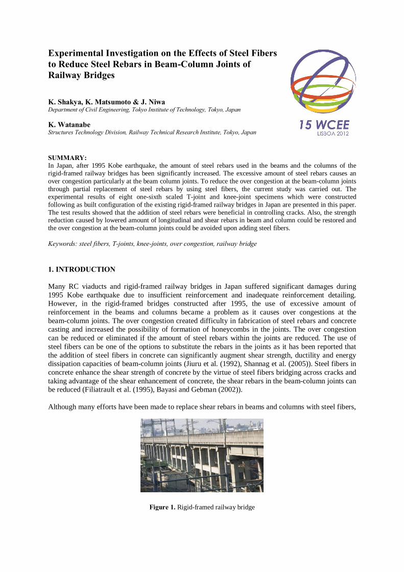
no efforts have been made so far to the authors’ knowledge to explore the consequences of substituting the certain amount of longitudinal steel rebars in beam-column joints with steel fibers. Hence, in the present study, an attempt is made to supplement the longitudinal and shear rebars in the beam-column joints of rigid-framed railway bridges (Figure 1), which covers large portion of railway bridges in Japan, with steel fibers. The main objective of this study is to avoid over congestion at the beam-column joints by reducing amount of steel rebars in the joints but without compromising the overall mechanical performance of the joints. This study focused on the failure mechanism, crack patterns, load-displacement relationships, energy dissipation and stiffness degradation to understand the structural behavior of beam-column joints with and without steel fibers. 2. TEST SETUP AND INSTRUMENTATION 2.1. Test specimens, material properties and rebar arrangement Based on the existing railway bridges in Japan, the material properties, specimen dimensions, detailing of steel rebars etc. were chosen for the test specimens. The considered existing bridge was designed following the Japanese Code, “Design Standards for Railway Structures and Commentary (Concrete Structures)” (Railway Technical Research Institute (2004)) and is referred as a prototype structure. The 1/6-scaled beam-column joint specimens are shown in Figure 2. The T-joint corresponds to half
(a) Bar arrangement and measurement system in T-joint
225 675
250
200
1187
31
3
Displacement transducer
Strain gauge
Load
Figure 2. Specimen details
(c) T-joint: Column and beam section, hook details
1030
330
675 175
250
Load
(b) Bar arrangement and measurement system in knee-joint
15∅ 35∅ 3 2 4
3∅ 12∅ 60 mm
5 6 7
(d) Knee-joint: Column and beam section, hook details
3 2 4
5 2
2 2 2
3 5 4 3 5 4 3 5 4
6
250
250
250
330
7 7 7
2
Column
Beam 168
250
250
200
1
1
1
1
1
1
1
1
2 2 2 2
11∅ 1 2
Unit: mm
Hinge
Hinge
Roller
Roller
TJ-ED TJ-1.5 TJ-1.0 TJ-0
KJ-ED KJ-1.5 KJ-1.0 KJ-0
(Numbers are corresponding to hook type)
Extension of hook
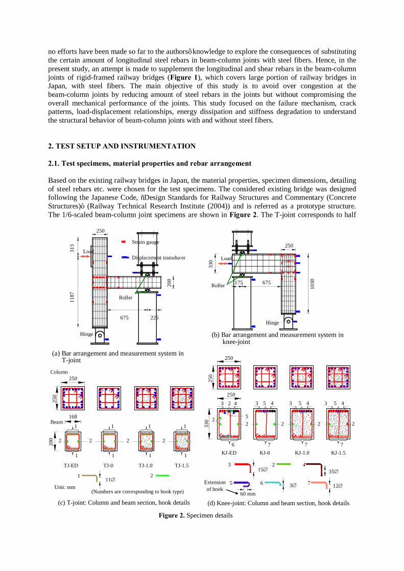
of the column heights above and below the intermediate link beam and a half of the intermediate link beam span and the knee-joint corresponds to a half of the column height and a half of the top beam span of a rigid-framed railway bridge. The cross-sectional size of columns were 250 mm × 250 mm in both T-joint and knee-joint specimens and the cross-sectional sizes of intermediate beam in T-joint specimens and top beam in knee-joint specimens were 168 mm × 200 mm and 250 mm × 330 mm, respectively. The concrete mix was prepared according to the procedure given in JSCE (2002a) to get concrete of compressive strength 30 N/mm2. The mix proportion and concrete strength are shown in Table 1. In the beam and column of control specimens, TJ-ED and KJ-ED, steel rebars were provided following the structural design of the existing bridge. In the designation of the specimens TJ and KJ stand for T-joint and Knee-joint and ED stands for Existing Design. The amount of steel rebars and its properties are tabulated in Table 1. All the steel rebars including longitudinal and shear rebars were of size D6 (nominal diameter of 6.35 mm) having yield strength of 325 N/mm2. The arrangement of steel rebars in beams and columns are shown in Figure 2. In all the 22 numbers of column rebars of TJ-ED and KJ-ED, 180° hook were provided at the end of rebars. In beam top and bottom rebars of TJ-ED, 90° hook with hook extension of 11∅ (∅ is rebar diameter) were provided while in top rebars of KJ-ED, out of 11 rebars, 3 rebars with 180° hook, 3 rebars with 90° hook having hook extension 35∅, 3 rebars with 90° hook having hook extension 15∅ and 2 rebars without hook were provided. All the 9 numbers of beam bottom rebars in KJ-ED were provided with 90° hook having hook extension of 3∅. No hooks were provided in the side face rebars. All the hook types and length of hook extension were decided as per reinforcement detailing of the existing railway bridge. The hoops in the columns of TJ-ED and KJ-ED were spaced at 85 mm. The stirrups in the beams of TJ-ED and KJ-ED were spaced at 70mm and 110 mm, respectively. In the specimens, TJ-0 TJ-1.0, TJ-1.5, KJ-0, KJ-1.0 and KJ-1.5, numbers of longitudinal rebars were reduced such that 1.2c bM M ≈ in T-joints and 1.2b cM M ≈ in knee-joints, where, bM is the flexural strength of a beam and cM is the flexural strength of a column. The calculated flexural capacities of beams and columns are shown in Figure 3. The numbers in the designation of specimens represents the percentage of provided steel fibers in the specimens. Hence, 0 refers to no steel fiber and 1.0 and 1.5 refer to 1.0% and 1.5% of hooked end steel fibers by volume had been added in concrete. In the columns of T-joints and knee-joints, the number of longitudinal rebars was reduced to
Table 1. Material properties and amount of steel rebars
Specimen
(N/mm2)
Steel fiber (%)
(N/mm2) Longitudinal rebar size*
Stirrup size*
Hoop size*
Percentage of steel (%)
Column Beam Longitudinal
rebar Hoop Longitudinal
rebar Stirrup
Prototype TJ
30.0 0 325 D32 D16 D16 0.99 0.57 1.4 0.64
TJ-ED 33.2 0 325 D6 D6 D6 1.11 0.65 1.58 0.51 TJ-0 32.5 0 325 D6 D6 D6 0.81 0.46 1.58 0.51
TJ-1.0 23.3 1.0 325 D6 D6 D6 0.81 0.46 1.58 0.51 TJ-1.5 30.0 1.5 325 D6 D6 D6 0.81 0.46 1.58 0.51
Prototype KJ
30.0 0 325 D32 D16 D16 0.99 0.57 0.92 0.28
KJ-ED 33.2 0 325 D6 D6 D6 1.11 0.65 0.97 0.29 KJ-0 31.8 0 325 D6 D6 D6 1.01 0.42 0.80 0.20
KJ-1.0 28.9 1.0 325 D6 D6 D6 1.01 0.42 0.80 0.20 KJ-1.5 30.1 1.5 325 D6 D6 D6 1.01 0.42 0.80 0.20
*Rebar size: Nominal diameter of rebars D6, D16 and D32 are 6.35 mm, 15.9 mm and 31.8 mm, respectively
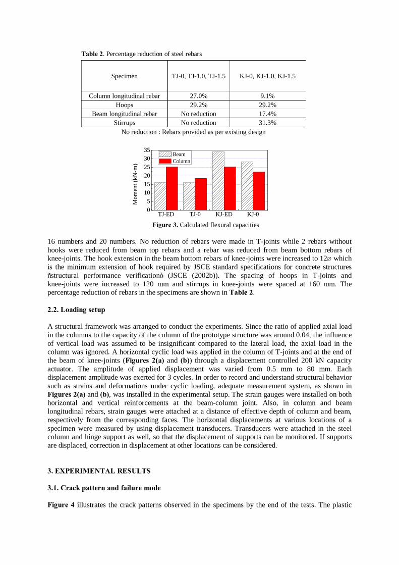
16 numbers and 20 numbers. No reduction of rebars were made in T-joints while 2 rebars without hooks were reduced from beam top rebars and a rebar was reduced from beam bottom rebars of knee-joints. The hook extension in the beam bottom rebars of knee-joints were increased to 12∅ which is the minimum extension of hook required by JSCE standard specifications for concrete structures “structural performance verification” (JSCE (2002b)). The spacing of hoops in T-joints and knee-joints were increased to 120 mm and stirrups in knee-joints were spaced at 160 mm. The percentage reduction of rebars in the specimens are shown in Table 2. 2.2. Loading setup A structural framework was arranged to conduct the experiments. Since the ratio of applied axial load in the columns to the capacity of the column of the prototype structure was around 0.04, the influence of vertical load was assumed to be insignificant compared to the lateral load, the axial load in the column was ignored. A horizontal cyclic load was applied in the column of T-joints and at the end of the beam of knee-joints (Figures 2(a) and (b)) through a displacement controlled 200 kN capacity actuator. The amplitude of applied displacement was varied from 0.5 mm to 80 mm. Each displacement amplitude was exerted for 3 cycles. In order to record and understand structural behavior such as strains and deformations under cyclic loading, adequate measurement system, as shown in Figures 2(a) and (b), was installed in the experimental setup. The strain gauges were installed on both horizontal and vertical reinforcements at the beam-column joint. Also, in column and beam longitudinal rebars, strain gauges were attached at a distance of effective depth of column and beam, respectively from the corresponding faces. The horizontal displacements at various locations of a specimen were measured by using displacement transducers. Transducers were attached in the steel column and hinge support as well, so that the displacement of supports can be monitored. If supports are displaced, correction in displacement at other locations can be considered. 3. EXPERIMENTAL RESULTS 3.1. Crack pattern and failure mode Figure 4 illustrates the crack patterns observed in the specimens by the end of the tests. The plastic
Table 2. Percentage reduction of steel rebars
Specimen TJ-0, TJ-1.0, TJ-1.5 KJ-0, KJ-1.0, KJ-1.5
Column longitudinal rebar 27.0% 9.1% Hoops 29.2% 29.2%
Beam longitudinal rebar No reduction 17.4% Stirrups No reduction 31.3%
No reduction : Rebars provided as per existing design
TJ-ED TJ-0 KJ-ED KJ-005
101520253035
Mom
ent (
kN-m
)
Beam Column
Figure 3. Calculated flexural capacities
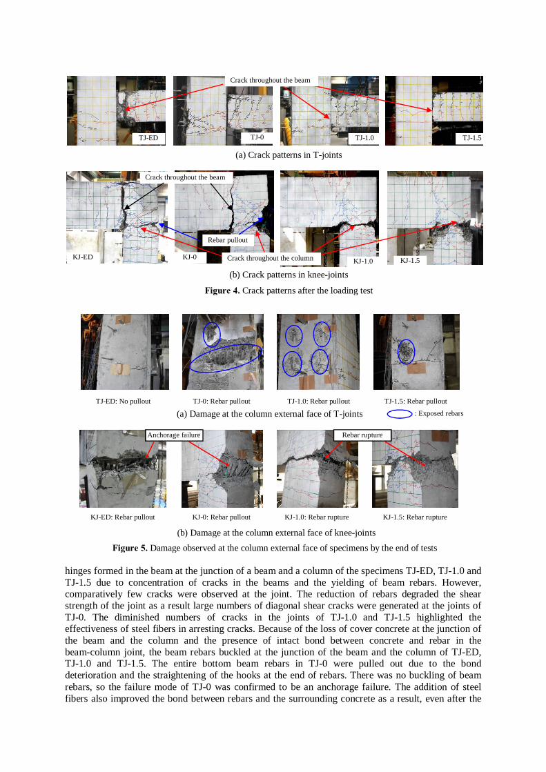
hinges formed in the beam at the junction of a beam and a column of the specimens TJ-ED, TJ-1.0 and TJ-1.5 due to concentration of cracks in the beams and the yielding of beam rebars. However, comparatively few cracks were observed at the joint. The reduction of rebars degraded the shear strength of the joint as a result large numbers of diagonal shear cracks were generated at the joints of TJ-0. The diminished numbers of cracks in the joints of TJ-1.0 and TJ-1.5 highlighted the effectiveness of steel fibers in arresting cracks. Because of the loss of cover concrete at the junction of the beam and the column and the presence of intact bond between concrete and rebar in the beam-column joint, the beam rebars buckled at the junction of the beam and the column of TJ-ED, TJ-1.0 and TJ-1.5. The entire bottom beam rebars in TJ-0 were pulled out due to the bond deterioration and the straightening of the hooks at the end of rebars. There was no buckling of beam rebars, so the failure mode of TJ-0 was confirmed to be an anchorage failure. The addition of steel fibers also improved the bond between rebars and the surrounding concrete as a result, even after the
Figure 4. Crack patterns after the loading test
Crack throughout the beam
TJ-ED TJ-0 TJ-1.0 TJ-1.5
(a) Crack patterns in T-joints
(b) Crack patterns in knee-joints
KJ-ED
Crack throughout the beam
KJ-0 KJ-1.0 KJ-1.5 Crack throughout the column
Rebar pullout
Anchorage failure Rebar rupture
KJ-ED: Rebar pullout
(b) Damage at the column external face of knee-joints
KJ-0: Rebar pullout KJ-1.0: Rebar rupture KJ-1.5: Rebar rupture
(a) Damage at the column external face of T-joints TJ-ED: No pullout TJ-0: Rebar pullout TJ-1.0: Rebar pullout TJ-1.5: Rebar pullout
Figure 5. Damage observed at the column external face of specimens by the end of tests
: Exposed rebars
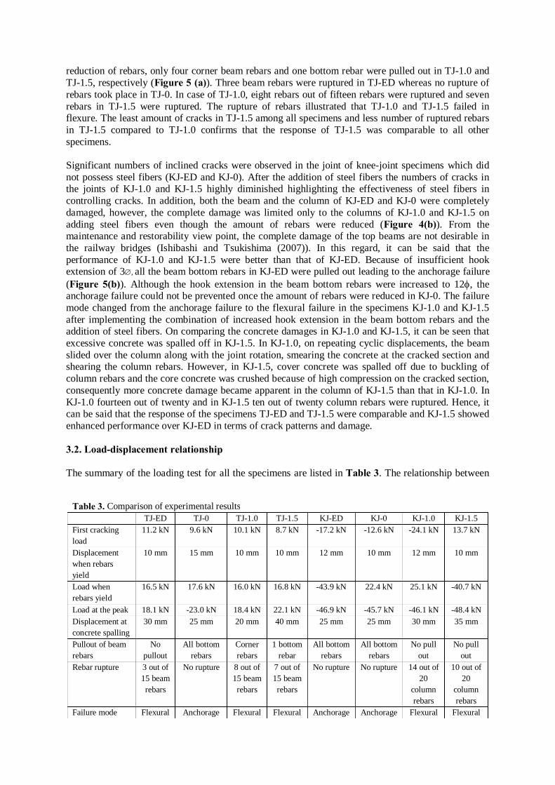
reduction of rebars, only four corner beam rebars and one bottom rebar were pulled out in TJ-1.0 and TJ-1.5, respectively (Figure 5 (a)). Three beam rebars were ruptured in TJ-ED whereas no rupture of rebars took place in TJ-0. In case of TJ-1.0, eight rebars out of fifteen rebars were ruptured and seven rebars in TJ-1.5 were ruptured. The rupture of rebars illustrated that TJ-1.0 and TJ-1.5 failed in flexure. The least amount of cracks in TJ-1.5 among all specimens and less number of ruptured rebars in TJ-1.5 compared to TJ-1.0 confirms that the response of TJ-1.5 was comparable to all other specimens. Significant numbers of inclined cracks were observed in the joint of knee-joint specimens which did not possess steel fibers (KJ-ED and KJ-0). After the addition of steel fibers the numbers of cracks in the joints of KJ-1.0 and KJ-1.5 highly diminished highlighting the effectiveness of steel fibers in controlling cracks. In addition, both the beam and the column of KJ-ED and KJ-0 were completely damaged, however, the complete damage was limited only to the columns of KJ-1.0 and KJ-1.5 on adding steel fibers even though the amount of rebars were reduced (Figure 4(b)). From the maintenance and restorability view point, the complete damage of the top beams are not desirable in the railway bridges (Ishibashi and Tsukishima (2007)). In this regard, it can be said that the performance of KJ-1.0 and KJ-1.5 were better than that of KJ-ED. Because of insufficient hook extension of 3∅, all the beam bottom rebars in KJ-ED were pulled out leading to the anchorage failure (Figure 5(b)). Although the hook extension in the beam bottom rebars were increased to 12φ, the anchorage failure could not be prevented once the amount of rebars were reduced in KJ-0. The failure mode changed from the anchorage failure to the flexural failure in the specimens KJ-1.0 and KJ-1.5 after implementing the combination of increased hook extension in the beam bottom rebars and the addition of steel fibers. On comparing the concrete damages in KJ-1.0 and KJ-1.5, it can be seen that excessive concrete was spalled off in KJ-1.5. In KJ-1.0, on repeating cyclic displacements, the beam slided over the column along with the joint rotation, smearing the concrete at the cracked section and shearing the column rebars. However, in KJ-1.5, cover concrete was spalled off due to buckling of column rebars and the core concrete was crushed because of high compression on the cracked section, consequently more concrete damage became apparent in the column of KJ-1.5 than that in KJ-1.0. In KJ-1.0 fourteen out of twenty and in KJ-1.5 ten out of twenty column rebars were ruptured. Hence, it can be said that the response of the specimens TJ-ED and TJ-1.5 were comparable and KJ-1.5 showed enhanced performance over KJ-ED in terms of crack patterns and damage. 3.2. Load-displacement relationship The summary of the loading test for all the specimens are listed in Table 3. The relationship between
Table 3. Comparison of experimental results
TJ-ED TJ-0 TJ-1.0 TJ-1.5 KJ-ED KJ-0 KJ-1.0 KJ-1.5 First cracking load
11.2 kN 9.6 kN 10.1 kN 8.7 kN -17.2 kN -12.6 kN -24.1 kN 13.7 kN
Displacement when rebars yield
10 mm 15 mm 10 mm 10 mm 12 mm 10 mm 12 mm 10 mm
Load when rebars yield
16.5 kN 17.6 kN 16.0 kN 16.8 kN -43.9 kN 22.4 kN 25.1 kN -40.7 kN
Load at the peak 18.1 kN -23.0 kN 18.4 kN 22.1 kN -46.9 kN -45.7 kN -46.1 kN -48.4 kN Displacement at concrete spalling
30 mm 25 mm 20 mm 40 mm 25 mm 25 mm 30 mm 35 mm
Pullout of beam rebars
No pullout
All bottom rebars
Corner rebars
1 bottom rebar
All bottom rebars
All bottom rebars
No pull out
No pull out
Rebar rupture 3 out of 15 beam rebars
No rupture 8 out of 15 beam rebars
7 out of 15 beam rebars
No rupture No rupture 14 out of 20
column rebars
10 out of 20
column rebars
Failure mode Flexural Anchorage Flexural Flexural Anchorage Anchorage Flexural Flexural
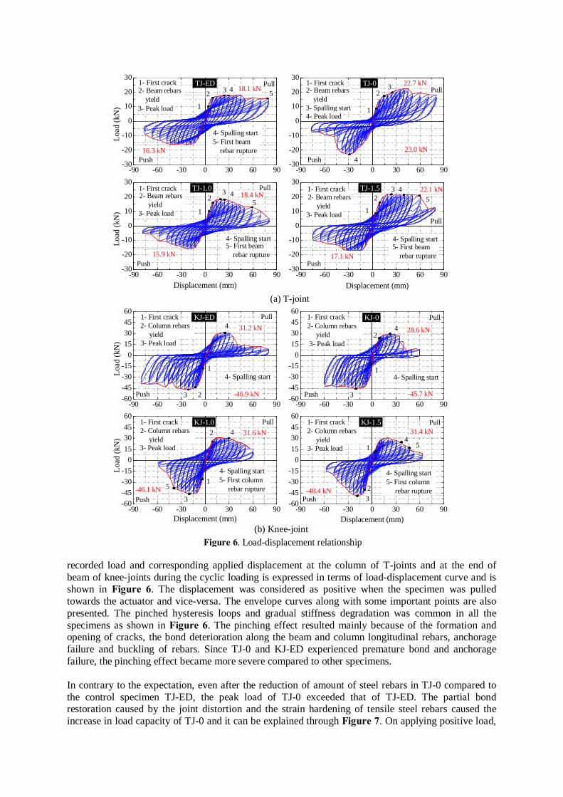
recorded load and corresponding applied displacement at the column of T-joints and at the end of beam of knee-joints during the cyclic loading is expressed in terms of load-displacement curve and is shown in Figure 6. The displacement was considered as positive when the specimen was pulled towards the actuator and vice-versa. The envelope curves along with some important points are also presented. The pinched hysteresis loops and gradual stiffness degradation was common in all the specimens as shown in Figure 6. The pinching effect resulted mainly because of the formation and opening of cracks, the bond deterioration along the beam and column longitudinal rebars, anchorage failure and buckling of rebars. Since TJ-0 and KJ-ED experienced premature bond and anchorage failure, the pinching effect became more severe compared to other specimens. In contrary to the expectation, even after the reduction of amount of steel rebars in TJ-0 compared to the control specimen TJ-ED, the peak load of TJ-0 exceeded that of TJ-ED. The partial bond restoration caused by the joint distortion and the strain hardening of tensile steel rebars caused the increase in load capacity of TJ-0 and it can be explained through Figure 7. On applying positive load,
Figure 6. Load-displacement relationship (b) Knee-joint
-90 -60 -30 0 30 60 90-60-45-30-15
015304560
-90 -60 -30 0 30 60 90-60-45-30-15
015304560
-90 -60 -30 0 30 60 90-60-45-30-15
015304560
-90 -60 -30 0 30 60 90-60-45-30-15
015304560
Load
(kN
)
1
23
4Pull
-46.9 kN
31.2 kN
Push
1- First crack2- Column rebars yield3- Peak load
4- Spalling start1
4Pull
28.6 kN
1- First crack2- Column rebars yield3- Peak load
4- Spalling start
2
Push 3 -45.7 kN
Load
(kN
)
Displacement (mm)
1
4Pull
31.6 kN1- First crack2- Column rebars yield3- Peak load
4- Spalling start
Push
2
3-46.1 kN
5- First column rebar rupture 5 5- First column
rebar rupture
5
Displacement (mm)
1
3
4
Pull
-48.4 kN
31.4 kN
Push
1- First crack2- Column rebars yield3- Peak load
4- Spalling start
2
KJ-ED
KJ-1.0
KJ-0
KJ-1.5
(a) T-joint
-90 -60 -30 0 30 60 90-30
-20
-10
0
10
20
30
-90 -60 -30 0 30 60 90-30
-20
-10
0
10
20
30-90 -60 -30 0 30 60 90
-30
-20
-10
0
10
20
30
-90 -60 -30 0 30 60 90-30
-20
-10
0
10
20
30
Loa
d (k
N)
TJ-ED
Displacement (mm)Displacement (mm)
16.3 kNPush
1
2 3 4 51- First crack2- Beam rebars yield3- Peak load
4- Spalling start5- First beam rebar rupture
18.1 kNPull
TJ-1.5
5- First beam rebar rupture
522.1 kN
Push
Pull
42.2 kN
17.1 kN
1- First crack2- Beam rebars yield3- Peak load
4- Spalling start
1
23 4
TJ-0
Push
Pull
23.0 kN4
1
23
22.71 kN1- First crack2- Beam rebars yield3- Spalling start 4- Peak load
22.7 kN
Loa
d (k
N)
TJ-1.0
15.9 kN
18.4 kN5
432
1
2- Beam rebars yield
5- First beam rebar rupture
3- Peak load
4- Spalling start
1- First crack
Push
Pull
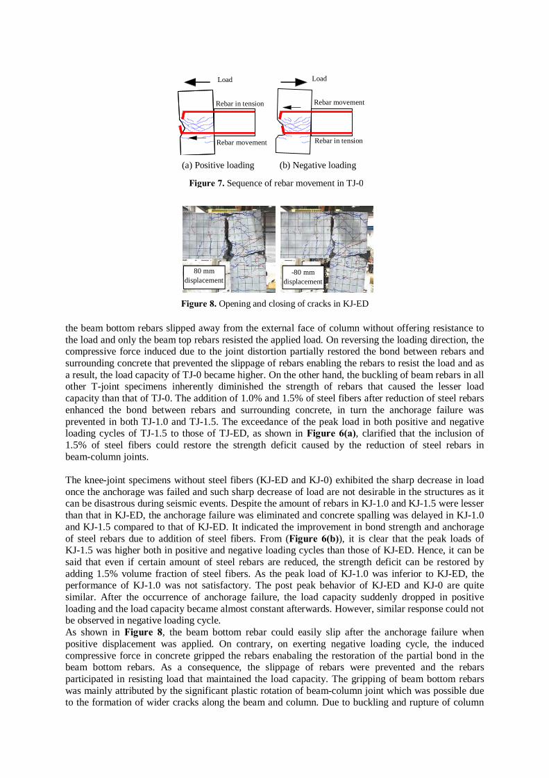
the beam bottom rebars slipped away from the external face of column without offering resistance to the load and only the beam top rebars resisted the applied load. On reversing the loading direction, the compressive force induced due to the joint distortion partially restored the bond between rebars and surrounding concrete that prevented the slippage of rebars enabling the rebars to resist the load and as a result, the load capacity of TJ-0 became higher. On the other hand, the buckling of beam rebars in all other T-joint specimens inherently diminished the strength of rebars that caused the lesser load capacity than that of TJ-0. The addition of 1.0% and 1.5% of steel fibers after reduction of steel rebars enhanced the bond between rebars and surrounding concrete, in turn the anchorage failure was prevented in both TJ-1.0 and TJ-1.5. The exceedance of the peak load in both positive and negative loading cycles of TJ-1.5 to those of TJ-ED, as shown in Figure 6(a), clarified that the inclusion of 1.5% of steel fibers could restore the strength deficit caused by the reduction of steel rebars in beam-column joints. The knee-joint specimens without steel fibers (KJ-ED and KJ-0) exhibited the sharp decrease in load once the anchorage was failed and such sharp decrease of load are not desirable in the structures as it can be disastrous during seismic events. Despite the amount of rebars in KJ-1.0 and KJ-1.5 were lesser than that in KJ-ED, the anchorage failure was eliminated and concrete spalling was delayed in KJ-1.0 and KJ-1.5 compared to that of KJ-ED. It indicated the improvement in bond strength and anchorage of steel rebars due to addition of steel fibers. From (Figure 6(b)), it is clear that the peak loads of KJ-1.5 was higher both in positive and negative loading cycles than those of KJ-ED. Hence, it can be said that even if certain amount of steel rebars are reduced, the strength deficit can be restored by adding 1.5% volume fraction of steel fibers. As the peak load of KJ-1.0 was inferior to KJ-ED, the performance of KJ-1.0 was not satisfactory. The post peak behavior of KJ-ED and KJ-0 are quite similar. After the occurrence of anchorage failure, the load capacity suddenly dropped in positive loading and the load capacity became almost constant afterwards. However, similar response could not be observed in negative loading cycle. As shown in Figure 8, the beam bottom rebar could easily slip after the anchorage failure when positive displacement was applied. On contrary, on exerting negative loading cycle, the induced compressive force in concrete gripped the rebars enabaling the restoration of the partial bond in the beam bottom rebars. As a consequence, the slippage of rebars were prevented and the rebars participated in resisting load that maintained the load capacity. The gripping of beam bottom rebars was mainly attributed by the significant plastic rotation of beam-column joint which was possible due to the formation of wider cracks along the beam and column. Due to buckling and rupture of column
Rebar in tension
(a) Positive loading
Load Load
Rebar movement Rebar in tension
Figure 7. Sequence of rebar movement in TJ-0
(b) Negative loading
Rebar movement
Figure 8. Opening and closing of cracks in KJ-ED
80 mm displacement
-80 mm displacement
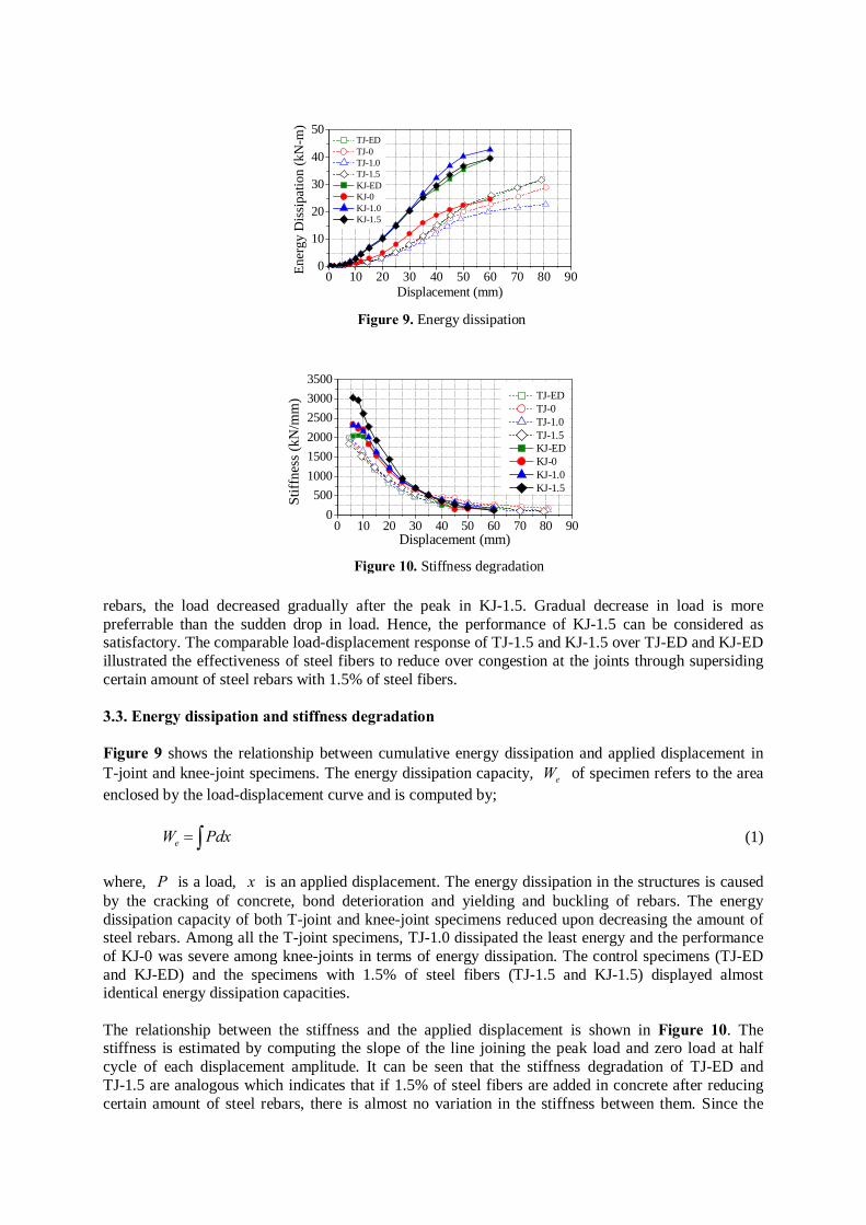
rebars, the load decreased gradually after the peak in KJ-1.5. Gradual decrease in load is more preferrable than the sudden drop in load. Hence, the performance of KJ-1.5 can be considered as satisfactory. The comparable load-displacement response of TJ-1.5 and KJ-1.5 over TJ-ED and KJ-ED illustrated the effectiveness of steel fibers to reduce over congestion at the joints through supersiding certain amount of steel rebars with 1.5% of steel fibers. 3.3. Energy dissipation and stiffness degradation Figure 9 shows the relationship between cumulative energy dissipation and applied displacement in T-joint and knee-joint specimens. The energy dissipation capacity, eW of specimen refers to the area enclosed by the load-displacement curve and is computed by;
eW Pdx= ∫ (1) where, P is a load, x is an applied displacement. The energy dissipation in the structures is caused by the cracking of concrete, bond deterioration and yielding and buckling of rebars. The energy dissipation capacity of both T-joint and knee-joint specimens reduced upon decreasing the amount of steel rebars. Among all the T-joint specimens, TJ-1.0 dissipated the least energy and the performance of KJ-0 was severe among knee-joints in terms of energy dissipation. The control specimens (TJ-ED and KJ-ED) and the specimens with 1.5% of steel fibers (TJ-1.5 and KJ-1.5) displayed almost identical energy dissipation capacities. The relationship between the stiffness and the applied displacement is shown in Figure 10. The stiffness is estimated by computing the slope of the line joining the peak load and zero load at half cycle of each displacement amplitude. It can be seen that the stiffness degradation of TJ-ED and TJ-1.5 are analogous which indicates that if 1.5% of steel fibers are added in concrete after reducing certain amount of steel rebars, there is almost no variation in the stiffness between them. Since the
0 10 20 30 40 50 60 70 80 900
10
20
30
40
50 TJ-ED TJ-0 TJ-1.0 TJ-1.5 KJ-ED KJ-0 KJ-1.0 KJ-1.5
Ener
gy D
issi
patio
n (k
N-m
)Displacement (mm)
Figure 9. Energy dissipation
0 10 20 30 40 50 60 70 80 900
500100015002000250030003500
Stiff
ness
(kN
/mm
)
Displacement (mm)
TJ-ED TJ-0 TJ-1.0 TJ-1.5 KJ-ED KJ-0 KJ-1.0 KJ-1.5
Figure 10. Stiffness degradation
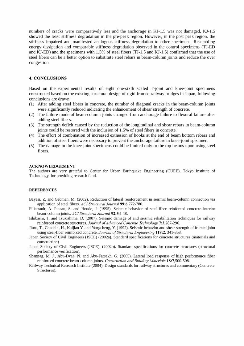
numbers of cracks were comparatively less and the anchorage in KJ-1.5 was not damaged, KJ-1.5 showed the least stiffness degradation in the pre-peak region. However, in the post peak region, the stiffness impaired and manifested analogous stiffness degradation to other specimens. Resembling energy dissipation and comparable stiffness degradation observed in the control specimens (TJ-ED and KJ-ED) and the specimens with 1.5% of steel fibers (TJ-1.5 and KJ-1.5) confirmed that the use of steel fibers can be a better option to substitute steel rebars in beam-column joints and reduce the over congestion. 4. CONCLUSIONS Based on the experimental results of eight one-sixth scaled T-joint and knee-joint specimens constructed based on the existing structural design of rigid-framed railway bridges in Japan, following conclusions are drawn: (1) After adding steel fibers in concrete, the number of diagonal cracks in the beam-column joints
were significantly reduced indicating the enhancement of shear strength of concrete. (2) The failure mode of beam-column joints changed from anchorage failure to flexural failure after
adding steel fibers. (3) The strength deficit caused by the reduction of the longitudinal and shear rebars in beam-column
joints could be restored with the inclusion of 1.5% of steel fibers in concrete. (4) The effort of combination of increased extnesion of hooks at the end of beam bottom rebars and
addition of steel fibers were necessary to prevent the anchorage failure in knee-joint specimen. (5) The damage in the knee-joint specimens could be limited only to the top beams upon using steel
fibers. ACKNOWLEDGEMENT The authors are very grateful to Center for Urban Earthquake Engineering (CUEE), Tokyo Institute of Technology, for providing research fund. REFERENCES Bayasi, Z. and Gebman, M. (2002). Reduction of lateral reinforcement in seismic beam-column connection via
application of steel fibers. ACI Structural Journal 99:6,772-780. Filiatrault, A. Pineau, S. and Houde, J. (1995). Seismic behavior of steel-fiber reinforced concrete interior
beam-column joints. ACI Structural Journal 92:5,1-10. Ishibashi, T. and Tsukishima, D. (2007). Seismic damage of and seismic rehabilitation techniques for railway
reinforced concrete structures. Journal of Advanced Concrete Technology 7:3,287-296. Jiuru, T., Chaobin, H., Kaijian Y. and Yongcheng, Y. (1992). Seismic behavior and shear strength of framed joint
using steel-fiber reinforced concrete. Journal of Structural Engineering 118:2, 341-358. Japan Society of Civil Engineers (JSCE) (2002a). Standard specifications for concrete structures (materials and
construction). Japan Society of Civil Engineers (JSCE). (2002b). Standard specifications for concrete structures (structural
performance verification). Shannag, M. J., Abu-Dyaa, N. and Abu-Farsakh, G. (2005). Lateral load response of high performance fiber
reinforced concrete beam-column joints. Construction and Building Materials 18:7,500-508. Railway Technical Research Institute (2004). Design standards for railway structures and commentary (Concrete
Structures).