Embed Size (px)
Citation preview
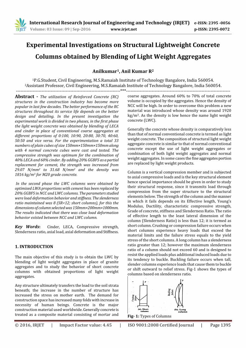
International Research Journal of Engineering and Technology (IRJET) e-ISSN: 2395 -0056
Volume: 03 Issue: 09 | Sep-2016 www.irjet.net p-ISSN: 2395-0072
© 2016, IRJET | Impact Factor value: 4.45 | ISO 9001:2008 Certified Journal | Page 1395
Experimental Investigations on Structural Lightweight Concrete
Columns obtained by Blending of Light Weight Aggregates
Anilkumar1, Anil Kumar R2
1P.G.Student, Civil Engineering, M.S.Ramaiah Institute of Technology Bangalore, India 560054. 2Assistant Professor, Civil Engineering, M.S.Ramaiah Institute of Technology Bangalore, India 560054.
---------------------------------------------------------------------***---------------------------------------------------------------------
Abstract - The utilization of Reinforced Concrete (RC) structures in the construction industry has become more popular in last few decades. The better performance of the RC structures throughout its service life depends on the better design and detailing. In the present investigation the experimental work is divided in two phases, in the first phase the light weight concrete was obtained by blending of LECA and cinder in place of conventional coarse aggregates at different proportions of 0:100, 10:90, 20:80, 30:70, 40:60, 50:50 and vice versa. For the experimentation a total 33 numbers of plain cubes of size 150mm×150mm×150mm along with 4 normal concrete cubes were cast and tested. The compressive strength was optimum for the combination of 40% LECA and 60% cinder. By adding 20% GGBFS as a partial replacement for cement, the strength was increased from 29.07 N/mm2 to 31.68 N/mm2 and the density was 1816 kg/m3 for M20 grade concrete.
In the second phase the LWC columns were obtained by optimised LWA proportions with cement has been replaced by 20% GGBFS in NCC and LWC columns. The parameters studied were load deformation behavior and stiffness. The slenderness ratio maintained was 8 (SR<12; short columns), for this the dimensions of column selected was 150mm×200mm×1000mm. The results indicated that there was close load deformation behavior existed between NCC and LWC column.
Key Words: Cinder, LECA, Compressive strength, Slenderness ratio, axial load, axial deformation and Stiffness.
1. INTRODUCTION The main objective of this study is to obtain the LWC by blending of light weight aggregates in place of granite aggregates and to study the behavior of short concrete columns with obtained proportions of light weight aggregates.
Any structure ultimately transfers the load to the soil strata beneath; the increase in the number of structure has increased the stress on mother earth. The demand for construction space has increased many folds with increase in necessity of human beings. Concrete is the major construction material used worldwide. Generally concrete is treated as a composite material consisting of mortar and
coarse aggregates. Around 60% to 70% of total concrete volume is occupied by the aggregates. Hence the density of NCC will be high. In order to overcome this problem a new material was introduced whose density was around 1920 kg/m3. As the density is low hence the name light weight concrete (LWC).
Generally the concrete whose density is comparatively less than that of normal conventional concrete is termed as light weight concrete. The composition of structural light weight aggregate concrete is similar to that of normal conventional concrete except the use of light weight aggregates or combination of both light weight aggregates and normal weight aggregates. In some cases the fine aggregates portion are replaced by light weight products.
Column is a vertical compression member and is subjected to axial compressive loads and is the key structural element hence special importance should be given in order to study their structural response, since it transmits load through compression from the super structure to the structural elements below. The strength of the column and the manner in which it fails depends on its Effective length, Young’s Modulus, Ductility, characteristic compressive strength, Grade of concrete, stiffness and Slenderness Ratio. The ratio of effective length to the least lateral dimension of the column (Slenderness Ratio) is less than 12; it is termed as short column. Crushing or compression failure occurs when short columns experience heavy loads that exceed the material limits and the failure stress equals to the yield stress of the short columns. A long column has a slenderness ratio greater than 12; however the maximum slenderness ratio of a column should not exceed 60 and is designed to resist the applied loads plus additional induced loads due to its tendency to buckle. Buckling failure occurs when tall, slender columns experience loads that cause them to buckle or shift outward to relief stress. Fig-1 shows the types of columns based on slenderness ratio.
Fig- 1: Types of Columns
International Research Journal of Engineering and Technology (IRJET) e-ISSN: 2395 -0056
Volume: 03 Issue: 09 | Sep-2016 www.irjet.net p-ISSN: 2395-0072
© 2016, IRJET | Impact Factor value: 4.45 | ISO 9001:2008 Certified Journal | Page 1396
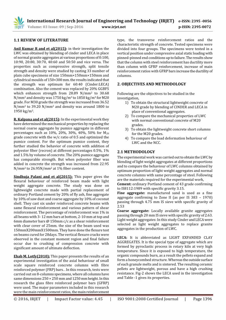
1.1 REVIEW OF LITERATURE
Anil Kumar R and et al(2015): in their investigation the LWC was obtained by blending of cinder and LECA in place of normal granite aggregates at various proportions of 0:100, 10:90, 20:80, 30:70, 40:60 and 50:50 and vice versa. The properties such as compressive strength, split tensile strength and density were studied by casting 33 number of plain cube specimens of size 150mm×150mm×150mm and cylindrical moulds of 150×300 mm. the results indicated that the strength was optimum for 60:40 (Cinder:LECA) combination. Also the cement was replaced by 20% GGBFS which enhances strength from 28.89 N/mm2 to 30.68 N/mm2 and density was 1750 kg/m3 to 1850 kg/m3 for M20 grade. For M30 grade the strength was increased from 36.52 N/mm2 to 39.20 N/mm2 and density was around 1800 to 1950 kg/m3.
R. Kalpana and et al(2015): In the experimental work they have determined the mechanical properties by replacing the normal coarse aggregate by pumice aggregate in different percentages such as 10%, 20%, 30%, 40%, 50% for M20 grade concrete with the w/c ratio of 0.5 and optimized the pumice content. For the optimum pumice content, they further studied the behavior of concrete with addition of polyester fiber (recron) at different percentages 0.5%, 1% and 1.5% by volume of concrete. The 20% pumice aggregate has comparable strength. But when polyester fiber was added in concrete the strength was increased from 22.95 N/mm2 to 26.95N/mm2 at 1% fiber content.
Sindhuja Palani and et al(2015): This paper gives the flexural behaviour of reinforced beam made with light weight aggregate concrete. The study was done on lightweight concrete made with partial replacement of ordinary Portland cement by 20% of fly ash, fine aggregate by 10% of saw dust and coarse aggregate by 10% of coconut shell. They cast six under reinforced concrete beams with same flexural reinforcement and various pattern of shear reinforcement. The percentage of reinforcement was 1% in all beams with 3- 12 mm bars at bottom, 2-10 mm at top and 6mm diameter bars @ 150mm c/c as a shear reinforcement with clear cover of 25mm. the size of the beam used was 150mmX200mmX1500mm. They have done the flexure test on beams cured for 28days. The vertical flexure cracks were observed in the constant moment region and final failure occur due to crushing of compression concrete with significant amount of ultimate deflection.
Ehab M. Lotfy(2010): This paper presents the results of an experimental investigation of the axial behaviour of small scale square reinforced concrete columns with fibre reinforced polymer (FRP) bars. . In this research, tests were carried out on 8-columns specimens, where all columns have same dimensions 250 × 250 mm and 1250 mm height. In this research the glass fibre reinforced polymer bars (GFRP) were used. The major parameters included in this research were the main reinforcement ratios, the main reinforcement
type, the transverse reinforcement ratios and the characteristic strength of concrete. Tested specimens were divided into four groups. The specimens were tested in a vertical position under compressive axial static loading with pinned-pinned end conditions up to failure. The results show that the column with steel reinforcement has ductility more than column with GFRP reinforcement, increase of main reinforcement ratios with GFRP bars increase the ductility of columns.
2. OBJECTIVES AND METHODOLOGY Following are the objectives to be studied in the investigation,
1) To obtain the structural lightweight concrete of M20 grade by blending of CINDER and LECA in place of conventional aggregates.
2) To compare the mechanical properties of LWC with normal conventional concrete of M20 grades.
3) To obtain the lightweight concrete short columns for the M20 grades.
4) To compare the load deformation behaviour of LWC and the NCC.
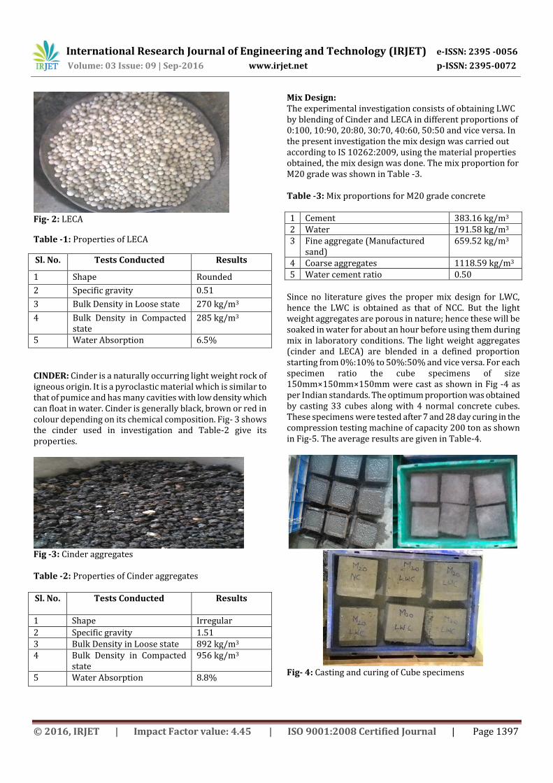
2.1 METHODOLOGY The experimental work was carried out to obtain the LWC by blending of light weight aggregates at different proportions and to compare the behaviour of LWC columns obtained by optimum proportion of light weight aggregates and normal concrete columns with same percentage of steel. Following are the materials required for the experimental work, Cement: ordinary Portland cement of 43 grade confirming to IS8112:1989 with specific gravity 3.15. Fine aggregate: manufactured sand is used as a fine aggregate confirming to Zone II (as per IS 383 – 1970) passing through 4.75 mm IS sieve with specific gravity of 2.53 Coarse aggregate: Locally available granite aggregates passing through 20 mm IS sieve with specific gravity of 2.63. Light weight aggregates: In this study Cinder and LECA were selected as light weight aggregates to replace granite aggregates in the production of LWC. LECA: It is abbreviated as LIGHT EXPANDED CLAY AGGREGATES. It is the special type of aggregate which are formed by pyroclastic process in rotary kiln at very high temperature. Since it is exposed to high temperature, the organic compounds burn, as a result the pellets expand and form a honeycombed structure. Whereas the outside surface of each granule melts and is sintered. The resulting ceramic pellets are lightweight, porous and have a high crushing resistance. Fig-2 shows the LECA used in the investigation and Table -1 gives its properties.
International Research Journal of Engineering and Technology (IRJET) e-ISSN: 2395 -0056
Volume: 03 Issue: 09 | Sep-2016 www.irjet.net p-ISSN: 2395-0072
© 2016, IRJET | Impact Factor value: 4.45 | ISO 9001:2008 Certified Journal | Page 1397
Fig- 2: LECA
Table -1: Properties of LECA
Sl. No. Tests Conducted Results
1 Shape Rounded
2 Specific gravity 0.51
3 Bulk Density in Loose state 270 kg/m3
4 Bulk Density in Compacted state
285 kg/m3
5 Water Absorption 6.5%
CINDER: Cinder is a naturally occurring light weight rock of igneous origin. It is a pyroclastic material which is similar to that of pumice and has many cavities with low density which can float in water. Cinder is generally black, brown or red in colour depending on its chemical composition. Fig- 3 shows the cinder used in investigation and Table-2 give its properties.
Fig -3: Cinder aggregates Table -2: Properties of Cinder aggregates Sl. No. Tests Conducted Results
1 Shape Irregular
2 Specific gravity 1.51 3 Bulk Density in Loose state 892 kg/m3 4 Bulk Density in Compacted
state 956 kg/m3
5 Water Absorption 8.8%
Mix Design: The experimental investigation consists of obtaining LWC by blending of Cinder and LECA in different proportions of 0:100, 10:90, 20:80, 30:70, 40:60, 50:50 and vice versa. In the present investigation the mix design was carried out according to IS 10262:2009, using the material properties obtained, the mix design was done. The mix proportion for M20 grade was shown in Table -3. Table -3: Mix proportions for M20 grade concrete 1 Cement 383.16 kg/m3 2 Water 191.58 kg/m3 3 Fine aggregate (Manufactured
sand) 659.52 kg/m3
4 Coarse aggregates 1118.59 kg/m3 5 Water cement ratio 0.50
Since no literature gives the proper mix design for LWC, hence the LWC is obtained as that of NCC. But the light weight aggregates are porous in nature; hence these will be soaked in water for about an hour before using them during mix in laboratory conditions. The light weight aggregates (cinder and LECA) are blended in a defined proportion starting from 0%:10% to 50%:50% and vice versa. For each specimen ratio the cube specimens of size 150mm×150mm×150mm were cast as shown in Fig -4 as per Indian standards. The optimum proportion was obtained by casting 33 cubes along with 4 normal concrete cubes. These specimens were tested after 7 and 28 day curing in the compression testing machine of capacity 200 ton as shown in Fig-5. The average results are given in Table-4.
Fig- 4: Casting and curing of Cube specimens
International Research Journal of Engineering and Technology (IRJET) e-ISSN: 2395 -0056
Volume: 03 Issue: 09 | Sep-2016 www.irjet.net p-ISSN: 2395-0072
© 2016, IRJET | Impact Factor value: 4.45 | ISO 9001:2008 Certified Journal | Page 1398
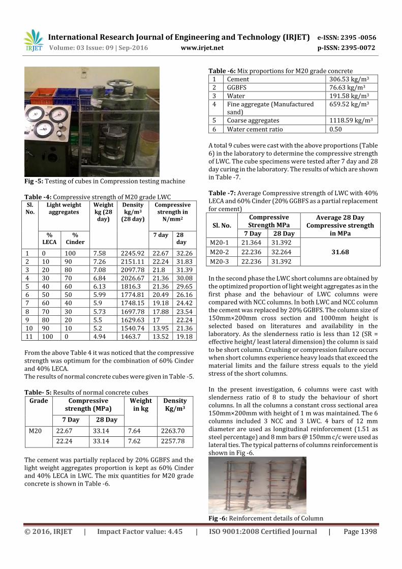
Fig -5: Testing of cubes in Compression testing machine Table -4: Compressive strength of M20 grade LWC Sl. No.
Light weight aggregates
Weight kg (28 day)
Density kg/m3
(28 day)
Compressive strength in
N/mm2
% LECA
% Cinder
7 day 28 day
1 0 100 7.58 2245.92 22.67 32.26 2 10 90 7.26 2151.11 22.24 31.83 3 20 80 7.08 2097.78 21.8 31.39 4 30 70 6.84 2026.67 21.36 30.08 5 40 60 6.13 1816.3 21.36 29.65 6 50 50 5.99 1774.81 20.49 26.16 7 60 40 5.9 1748.15 19.18 24.42
8 70 30 5.73 1697.78 17.88 23.54 9 80 20 5.5 1629.63 17 22.24 10 90 10 5.2 1540.74 13.95 21.36 11 100 0 4.94 1463.7 13.52 19.18 From the above Table 4 it was noticed that the compressive strength was optimum for the combination of 60% Cinder and 40% LECA. The results of normal concrete cubes were given in Table -5. Table- 5: Results of normal concrete cubes
Grade Compressive strength (MPa)
Weight in kg
Density Kg/m3
7 Day 28 Day
M20 22.67 33.14 7.64 2263.70
22.24 33.14 7.62 2257.78
The cement was partially replaced by 20% GGBFS and the light weight aggregates proportion is kept as 60% Cinder and 40% LECA in LWC. The mix quantities for M20 grade concrete is shown in Table -6.
Table -6: Mix proportions for M20 grade concrete 1 Cement 306.53 kg/m3 2 GGBFS 76.63 kg/m3
3 Water 191.58 kg/m3 4 Fine aggregate (Manufactured
sand) 659.52 kg/m3
5 Coarse aggregates 1118.59 kg/m3
6 Water cement ratio 0.50 A total 9 cubes were cast with the above proportions (Table 6) in the laboratory to determine the compressive strength of LWC. The cube specimens were tested after 7 day and 28 day curing in the laboratory. The results of which are shown in Table -7. Table -7: Average Compressive strength of LWC with 40% LECA and 60% Cinder (20% GGBFS as a partial replacement for cement)
Sl. No. Compressive Strength MPa
Average 28 Day Compressive strength
in MPa 7 Day 28 Day
M20-1 21.364 31.392
31.68 M20-2 22.236 32.264
M20-3 22.236 31.392
In the second phase the LWC short columns are obtained by the optimized proportion of light weight aggregates as in the first phase and the behaviour of LWC columns were compared with NCC columns. In both LWC and NCC column the cement was replaced by 20% GGBFS. The column size of 150mm×200mm cross section and 1000mm height is selected based on literatures and availability in the laboratory. As the slenderness ratio is less than 12 (SR = effective height/ least lateral dimension) the column is said to be short column. Crushing or compression failure occurs when short columns experience heavy loads that exceed the material limits and the failure stress equals to the yield stress of the short columns. In the present investigation, 6 columns were cast with slenderness ratio of 8 to study the behaviour of short columns. In all the columns a constant cross sectional area 150mm×200mm with height of 1 m was maintained. The 6 columns included 3 NCC and 3 LWC. 4 bars of 12 mm diameter are used as longitudinal reinforcement (1.51 as steel percentage) and 8 mm bars @ 150mm c/c were used as lateral ties. The typical patterns of columns reinforcement is shown in Fig -6.
Fig -6: Reinforcement details of Column
International Research Journal of Engineering and Technology (IRJET) e-ISSN: 2395 -0056
Volume: 03 Issue: 09 | Sep-2016 www.irjet.net p-ISSN: 2395-0072
© 2016, IRJET | Impact Factor value: 4.45 | ISO 9001:2008 Certified Journal | Page 1399
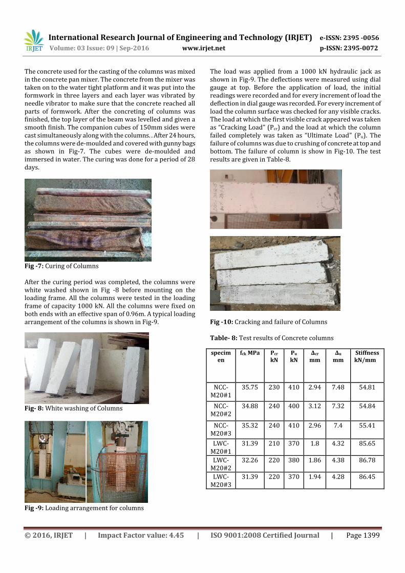
The concrete used for the casting of the columns was mixed in the concrete pan mixer. The concrete from the mixer was taken on to the water tight platform and it was put into the formwork in three layers and each layer was vibrated by needle vibrator to make sure that the concrete reached all parts of formwork. After the concreting of columns was finished, the top layer of the beam was levelled and given a smooth finish. The companion cubes of 150mm sides were cast simultaneously along with the columns. . After 24 hours, the columns were de-moulded and covered with gunny bags as shown in Fig-7. The cubes were de-moulded and immersed in water. The curing was done for a period of 28 days.
Fig -7: Curing of Columns After the curing period was completed, the columns were white washed shown in Fig -8 before mounting on the loading frame. All the columns were tested in the loading frame of capacity 1000 kN. All the columns were fixed on both ends with an effective span of 0.96m. A typical loading arrangement of the columns is shown in Fig-9.
Fig- 8: White washing of Columns
Fig -9: Loading arrangement for columns
The load was applied from a 1000 kN hydraulic jack as shown in Fig-9. The deflections were measured using dial gauge at top. Before the application of load, the initial readings were recorded and for every increment of load the deflection in dial gauge was recorded. For every increment of load the column surface was checked for any visible cracks. The load at which the first visible crack appeared was taken as “Cracking Load” (Pcr) and the load at which the column failed completely was taken as “Ultimate Load” (Pu). The failure of columns was due to crushing of concrete at top and bottom. The failure of column is show in Fig-10. The test results are given in Table-8.
Fig -10: Cracking and failure of Columns
Table- 8: Test results of Concrete columns
specimen
fck MPa Pcr kN
Pu kN
∆cr mm
∆u mm
Stiffness kN/mm
NCC-M20#1
35.75 230 410 2.94 7.48 54.81
NCC-M20#2
34.88 240 400 3.12 7.32 54.84
NCC-M20#3
35.32 240 410 2.96 7.4 55.41
LWC-M20#1
31.39 210 370 1.8 4.32 85.65
LWC-M20#2
32.26 220 380 1.86 4.38 86.78
LWC-M20#3
31.39 220 370 1.94 4.28 86.45
International Research Journal of Engineering and Technology (IRJET) e-ISSN: 2395 -0056
Volume: 03 Issue: 09 | Sep-2016 www.irjet.net p-ISSN: 2395-0072
© 2016, IRJET | Impact Factor value: 4.45 | ISO 9001:2008 Certified Journal | Page 1400
3. RESULTS AND DISCUSSION
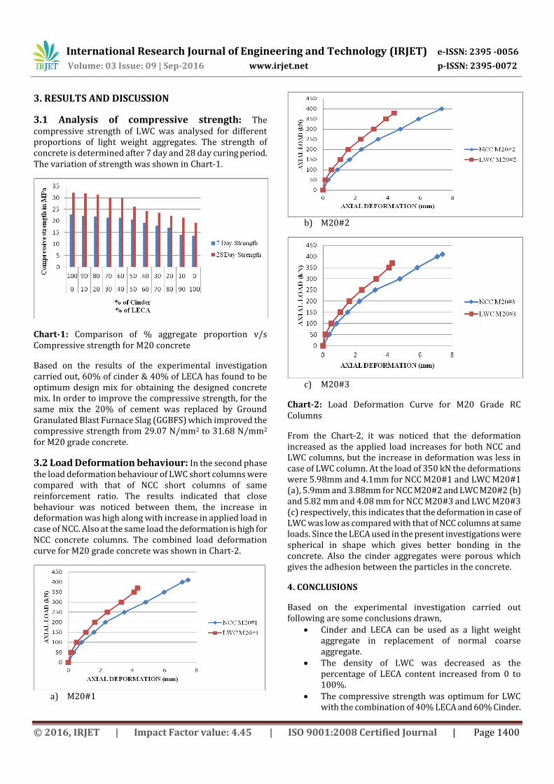
3.1 Analysis of compressive strength: The compressive strength of LWC was analysed for different proportions of light weight aggregates. The strength of concrete is determined after 7 day and 28 day curing period. The variation of strength was shown in Chart-1.
Chart-1: Comparison of % aggregate proportion v/s Compressive strength for M20 concrete
Based on the results of the experimental investigation carried out, 60% of cinder & 40% of LECA has found to be optimum design mix for obtaining the designed concrete mix. In order to improve the compressive strength, for the same mix the 20% of cement was replaced by Ground Granulated Blast Furnace Slag (GGBFS) which improved the compressive strength from 29.07 N/mm2 to 31.68 N/mm2 for M20 grade concrete.
3.2 Load Deformation behaviour: In the second phase the load deformation behaviour of LWC short columns were compared with that of NCC short columns of same reinforcement ratio. The results indicated that close behaviour was noticed between them, the increase in deformation was high along with increase in applied load in case of NCC. Also at the same load the deformation is high for NCC concrete columns. The combined load deformation curve for M20 grade concrete was shown in Chart-2.
a) M20#1
b) M20#2
c) M20#3
Chart-2: Load Deformation Curve for M20 Grade RC Columns
From the Chart-2, it was noticed that the deformation increased as the applied load increases for both NCC and LWC columns, but the increase in deformation was less in case of LWC column. At the load of 350 kN the deformations were 5.98mm and 4.1mm for NCC M20#1 and LWC M20#1 (a), 5.9mm and 3.88mm for NCC M20#2 and LWC M20#2 (b) and 5.82 mm and 4.08 mm for NCC M20#3 and LWC M20#3 (c) respectively, this indicates that the deformation in case of LWC was low as compared with that of NCC columns at same loads. Since the LECA used in the present investigations were spherical in shape which gives better bonding in the concrete. Also the cinder aggregates were porous which gives the adhesion between the particles in the concrete.
4. CONCLUSIONS
Based on the experimental investigation carried out following are some conclusions drawn,
Cinder and LECA can be used as a light weight aggregate in replacement of normal coarse aggregate.
The density of LWC was decreased as the percentage of LECA content increased from 0 to 100%.
The compressive strength was optimum for LWC with the combination of 40% LECA and 60% Cinder.
International Research Journal of Engineering and Technology (IRJET) e-ISSN: 2395 -0056
Volume: 03 Issue: 09 | Sep-2016 www.irjet.net p-ISSN: 2395-0072
© 2016, IRJET | Impact Factor value: 4.45 | ISO 9001:2008 Certified Journal | Page 1401
When 20% GGBFS was added as a partial replacement of cement has increased the compressive strength from 29.07 N/mm2 to 31.68 N/mm2 for M20 grade.
For the optimum combination of light weight aggregates in LWC the density was around 1816 kg/m3 which was less that of normal concrete 2260 kg/m3.
The load deformation behaviour was almost same for LWC and NCC column but the increment of deformation as applied load increased was slightly higher in case of NCC column than in LWC column.
At the same load the deformation of LWC columns was lesser than that of NCC columns.
REFERENCES
1. Anil Kumar R, Dr. P Prakash July-2015 “Studies on Structural Light Weight Concrete by Blending Light Weight Aggregates” International Journal of Innovative Research in Engineering & Management, India Volume-2, Issue-4, pp 48-52.
2. Anil Kumar R, Dr.P.Prakash October 2015 “Mechanical Properties of Structural Light Weight Concrete by Blending Cinder & LECA” International Advanced Research Journal in Science, Engineering and Technology India, Vol. 2, Issue 10, , pp 64-67.
3. E.Hanuman Sai Gupta, V.Giridhar Kumar July 2015 “Investigations on Properties of Light Weight Cinder Aggregate Concrete” International Journal of Engineering Research and Development, Volume 11, Issue 07, pp 50-59.
4. R. Kalpana, P. S. Kothai 2015 “Study on Properties of Fibre Reinforced Light Weight Aggregate Concrete” International Journal for Scientific Research & Development, India, Vol. 3, Issue 02, ISSN (online): 2321-0613, pp 1876 – 1879.
5. Sindhuja Palani , Dr. N. Sakthiswaren May 2015 “Flexural Behaviour of Reinforced Beam Made With Light Weight Aggregate Concrete” International Journal of Innovative Research in Science, Engineering and Technology, Vol. 4, Special Issue 6, pp 1751-1755.
6. Jihad Hamad Mohammed , Ali Jihad Hamad 2014 “A classification of lightweight concrete: materials, properties and application review” International Journal of Advanced Engineering Applications, Vol.7, Iss.1, pp.52-57.
7. A.M.N.Kashyap, G.Sasikala February 2014 “An Experimental Study on Compressive Strength of Steel Fibre Reinforced Light Weight Aggregate (Pumice Stone) Concrete” International Journal of Engineering Research and Development e-ISSN: 2278-067X, Volume 9, Issue 12 , pp 21-25.
8. Dr. V.Bhaskar Desai, Mr. A. Sathyam February 2014 “Some Studies on Strength Properties of Light Weight Cinder Aggregate Concrete” International
Journal of Scientific and Research Publications, India, ISSN 2250-3153, Volume 4, Issue 2.
9. Wasan Q. Fayyadh June 2013 “Using the Fly Ash to Reduce the Steel Corrosion in Lightweight Concrete” Journal of University of Thi-Qar Vol.8 No.3.
10. A. Sivakumar and P. Gomathi February 2012 “Pelletized fly ash lightweight aggregate concrete: A promising material” Journal of Civil Engineering and Construction Technology Vol. 3(2), pp 42-48.
11. Ehab M.Lotfy 2010 “Behaviour of Reinforced Concrete Short Columns with Fiber Reinforced Polymer bars” International Journal of Civil and Structural Engineering” Volume 1, No.3, pp 545-557.
12. Satjapan Leelatanon, Suthon Srivaro and Nirundorn Matan 2010 “Compressive strength and ductility of short concrete columns reinforced by bamboo”, pp 419-424.
13. K. Dhir, R. G. C. Mays, and H. C. Chua November 1984 “Lightweight structural concrete with Aglite aggregate: mix design and properties” The International Journal of Cement Composites and Lightweight Concrete, Volume 6, Number 4 pp 249-261.
14. ACI 213R-03 “Guide for Structural Lightweight-Aggregate Concrete”.
15. ACI 211.2-98 “Standard Practice for Selecting Proportions for Structural Lightweight Concrete”.
16. IS 456:2000, [Reaffirmed 2005], “Plain and Reinforced Concrete – Code of Practice”, Bureau of Indian Standards, New Delhi, India.
17. IS8112:1989, “Specifications for 43 grade Ordinary Portland Cement” Bureau of Indian Standards, New Delhi, India.
18. IS 383:1970, “Specifications for Coarse and Fine aggregates from Natural Sources for Concrete” Bureau of Indian Standards, New Delhi, India.
BIOGRAPHIES
NAME: Anilkumar M.Tech in Structural Engineering Department of Civil Engineering College: M S Ramaiah Institute of Technology, Bangalore
[email protected] NAME: Anil Kumar R Qualification: B.E., M.Tech in Structural Engineering, (Ph.D) Designation: Assistant Professor Department: Civil Engineering College: M.S.Ramaiah Institute of Technology, Mathikere, Bangalore [email protected]