Embed Size (px)
Citation preview
EXPERIMENTAL RELEASES OF LIQUID HYDROGEN†
P. Hooker1, D. B. Willoughby1, J. Hall1 and M. Royle2
1Health & Safety Laboratory UK Health and Safety Laboratory, Buxton, Derbyshire, SK17 9JN, United Kingdom2Health & Safety Executive UK Health and Safety Laboratory, Buxton, Derbyshire, SK17 9JN, United Kingdom
Tel 01298 218813. E-mail: [email protected]
If the hydrogen economy is to progress, more hydrogen fuelling stations are required. In the short
term, in the absence of a hydrogen distribution network, the most likely means of supplying the
fuelling stations will be by liquid hydrogen road tanker. The development will clearly increase
the number of tanker offloading operations significantly and these may need to be performed in
more challenging environments with close proximity to the general public.
The work described in this paper was commissioned in order to determine the hazards associated
with liquid hydrogen spills onto the ground at rates typical for a tanker hose failure during
offloading.
Experiments were performed to investigate spills of liquid hydrogen at a rate of 60 litres per
minute. Measurements were made on unignited and ignited releases. These included:
. Concentration of hydrogen in air, thermal gradient in the concrete substrate, liquid pool for-
mation, temperatures within the pool
. Flame velocity within the cloud, thermal radiation, IR and visible spectrum video records
. Sound pressure measurements
. An estimation of the extent of the flammable cloud was made from visual observation, video, IR
camera footage and the use of a variable position ignition source
KEYWORDS: LH2, Flame speed, Thermal radiation, Hydrogen concentration, Flammable cloud, Liquid
pool, Explosion
1. INTRODUCTIONCryogenic liquid storage and transfer has been safely exe-cuted for many years in secure and regulated industrialsites. However its use in relatively congested, highly popu-lated urban areas presents a new set of problems in relationto security, safety and associated planning. Research isneeded to identify and address safety issues relating tobulk liquid hydrogen storage and transfer facilities associ-ated with hydrogen refuelling stations located in urbanenvironments.
Liquid hydrogen has significantly different propertiesto other more common cryogenic gases, as can be seen fromthe values presented in Table 1.
It can be seen from these properties that attempting tosimulate the release behaviour of liquid hydrogen based onother more easily handled cryogens is unlikely to yielduseful results. The liquid phase has very low density com-pared to the other industrial cryogenic liquids and thevapour phase at the boiling temperature is only just nega-tively buoyant in ambient air (air density approximately1.2 kg/m3)(1). Furthermore, a release of liquid hydrogencan result in significant cooling of the surroundingscausing condensation of nitrogen and oxygen from the airand even the freezing of these gases to produce a solid.
In addition, the general combustion properties, suchas flame speed and ignition behaviour, for a cool, dense
vapour cloud of hydrogen with high proportions of con-densed water present are unknown and therefore need tobe studied.
This paper gives an overview of experimental work toinvestigate the behaviour of liquid hydrogen released toatmosphere in both un-ignited and ignited scenarios.
2. EXPERIMENTAL AIMSA number of distinct areas of spill behaviour were investi-gated:
. Hydrogen dispersion from unignited spills
. On ground liquid spill formation
. Spills into free air
. Spill behaviour with respect to specific storage con-ditions
. Flame speed and extent from ignited spills
. Thermal radiation from ignited spills
. Sound pressure level measurement from ignited hydro-gen clouds.
All the releases made were chosen to replicate areasonably foreseeable release from the failure of a transferhose coupling during LH2 transfer. Catastrophic failure ofthe containment vessel was not investigated as it is con-sidered to be a much less likely event.
†# Crown Copyright 2012. This article is published with the permission of the Controller of HMSO and the Queen’s Printer for Scotland.
SYMPOSIUM SERIES NO. 158 Hazards XXIII # 2012 Crown Copyright
496
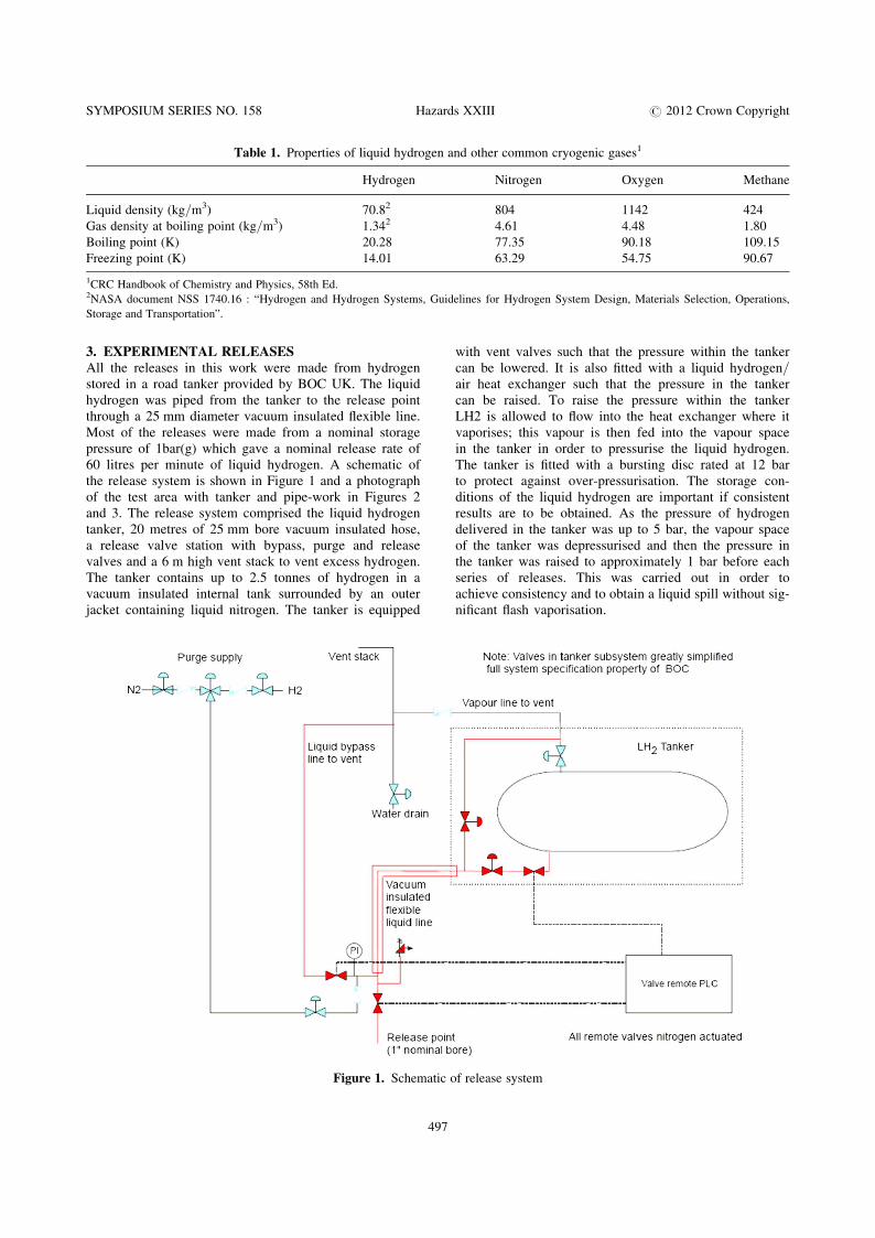
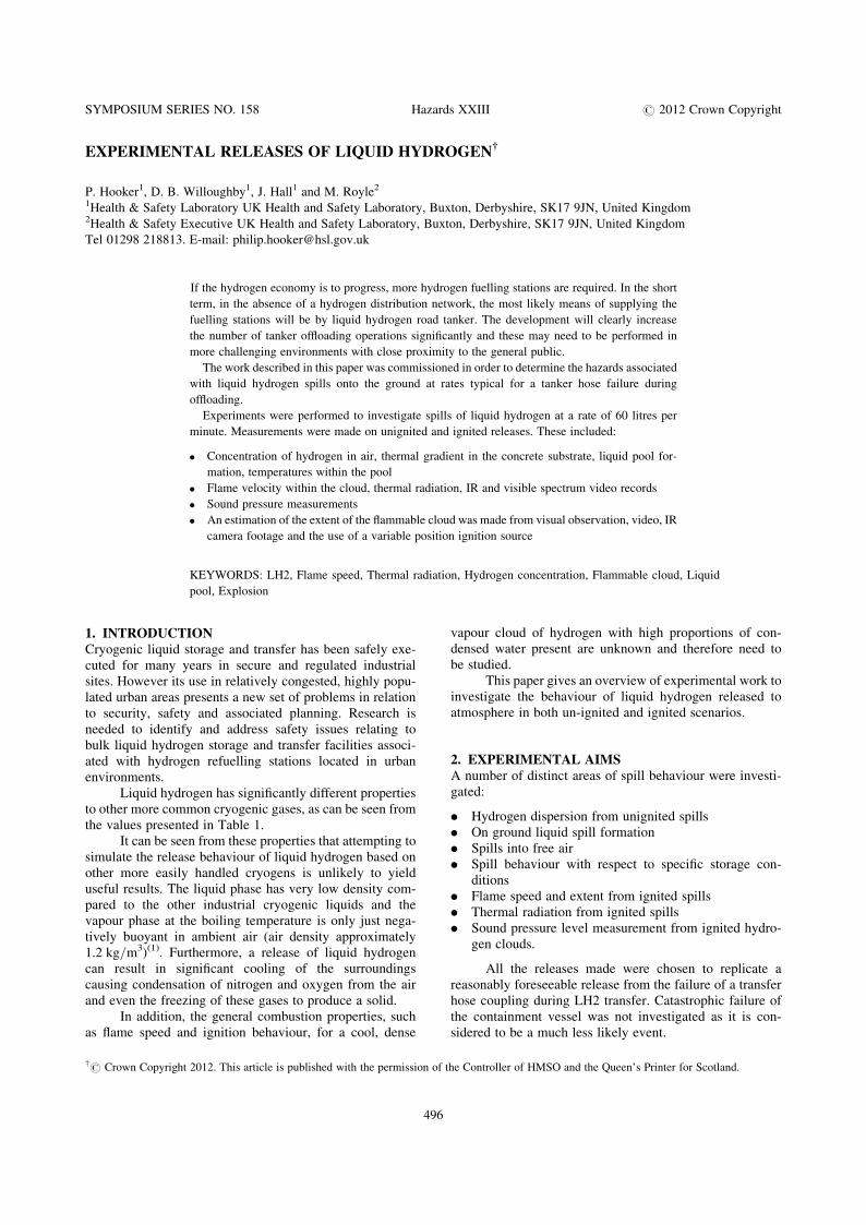
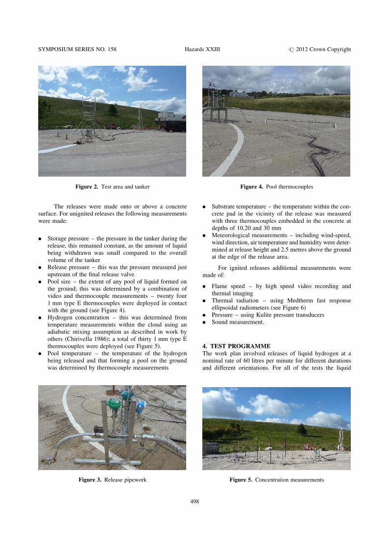
3. EXPERIMENTAL RELEASESAll the releases in this work were made from hydrogenstored in a road tanker provided by BOC UK. The liquidhydrogen was piped from the tanker to the release pointthrough a 25 mm diameter vacuum insulated flexible line.Most of the releases were made from a nominal storagepressure of 1bar(g) which gave a nominal release rate of60 litres per minute of liquid hydrogen. A schematic ofthe release system is shown in Figure 1 and a photographof the test area with tanker and pipe-work in Figures 2and 3. The release system comprised the liquid hydrogentanker, 20 metres of 25 mm bore vacuum insulated hose,a release valve station with bypass, purge and releasevalves and a 6 m high vent stack to vent excess hydrogen.The tanker contains up to 2.5 tonnes of hydrogen in avacuum insulated internal tank surrounded by an outerjacket containing liquid nitrogen. The tanker is equipped
with vent valves such that the pressure within the tankercan be lowered. It is also fitted with a liquid hydrogen/air heat exchanger such that the pressure in the tankercan be raised. To raise the pressure within the tankerLH2 is allowed to flow into the heat exchanger where itvaporises; this vapour is then fed into the vapour spacein the tanker in order to pressurise the liquid hydrogen.The tanker is fitted with a bursting disc rated at 12 barto protect against over-pressurisation. The storage con-ditions of the liquid hydrogen are important if consistentresults are to be obtained. As the pressure of hydrogendelivered in the tanker was up to 5 bar, the vapour spaceof the tanker was depressurised and then the pressure inthe tanker was raised to approximately 1 bar before eachseries of releases. This was carried out in order toachieve consistency and to obtain a liquid spill without sig-nificant flash vaporisation.
Table 1. Properties of liquid hydrogen and other common cryogenic gases1
Hydrogen Nitrogen Oxygen Methane
Liquid density (kg/m3) 70.82 804 1142 424
Gas density at boiling point (kg/m3) 1.342 4.61 4.48 1.80
Boiling point (K) 20.28 77.35 90.18 109.15
Freezing point (K) 14.01 63.29 54.75 90.67
1CRC Handbook of Chemistry and Physics, 58th Ed.2NASA document NSS 1740.16 : “Hydrogen and Hydrogen Systems, Guidelines for Hydrogen System Design, Materials Selection, Operations,
Storage and Transportation”.
Figure 1. Schematic of release system
SYMPOSIUM SERIES NO. 158 Hazards XXIII # 2012 Crown Copyright
497
The releases were made onto or above a concretesurface. For unignited releases the following measurementswere made:
. Storage pressure – the pressure in the tanker during therelease, this remained constant, as the amount of liquidbeing withdrawn was small compared to the overallvolume of the tanker
. Release pressure – this was the pressure measured justupstream of the final release valve
. Pool size – the extent of any pool of liquid formed onthe ground; this was determined by a combination ofvideo and thermocouple measurements – twenty four1 mm type E thermocouples were deployed in contactwith the ground (see Figure 4).
. Hydrogen concentration – this was determined fromtemperature measurements within the cloud using anadiabatic mixing assumption as described in work byothers (Chirivella 1986); a total of thirty 1 mm type Ethermocouples were deployed (see Figure 5).
. Pool temperature – the temperature of the hydrogenbeing released and that forming a pool on the groundwas determined by thermocouple measurements
. Substrate temperature – the temperature within the con-crete pad in the vicinity of the release was measuredwith three thermocouples embedded in the concrete atdepths of 10,20 and 30 mm
. Meteorological measurements – including wind-speed,wind direction, air temperature and humidity were deter-mined at release height and 2.5 metres above the groundat the edge of the release area.
For ignited releases additional measurements weremade of:
. Flame speed – by high speed video recording andthermal imaging
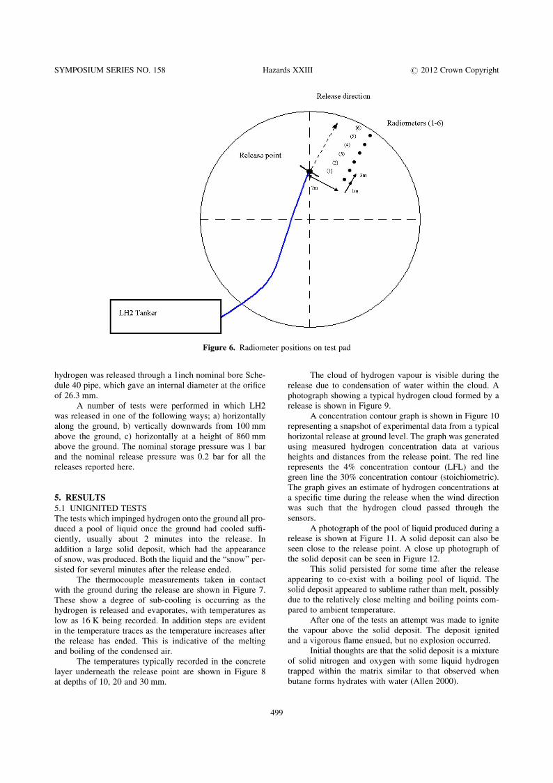
. Thermal radiation – using Medtherm fast responseellipsoidal radiometers (see Figure 6)
. Pressure – using Kulite pressure transducers
. Sound measurement.
4. TEST PROGRAMMEThe work plan involved releases of liquid hydrogen at anominal rate of 60 litres per minute for different durationsand different orientations. For all of the tests the liquid
Figure 4. Pool thermocouples
Figure 5. Concentration measurements
Figure 2. Test area and tanker
Figure 3. Release pipework
SYMPOSIUM SERIES NO. 158 Hazards XXIII # 2012 Crown Copyright
498
hydrogen was released through a 1inch nominal bore Sche-dule 40 pipe, which gave an internal diameter at the orificeof 26.3 mm.
A number of tests were performed in which LH2was released in one of the following ways; a) horizontallyalong the ground, b) vertically downwards from 100 mmabove the ground, c) horizontally at a height of 860 mmabove the ground. The nominal storage pressure was 1 barand the nominal release pressure was 0.2 bar for all thereleases reported here.
5. RESULTS
5.1 UNIGNITED TESTSThe tests which impinged hydrogen onto the ground all pro-duced a pool of liquid once the ground had cooled suffi-ciently, usually about 2 minutes into the release. Inaddition a large solid deposit, which had the appearanceof snow, was produced. Both the liquid and the “snow” per-sisted for several minutes after the release ended.
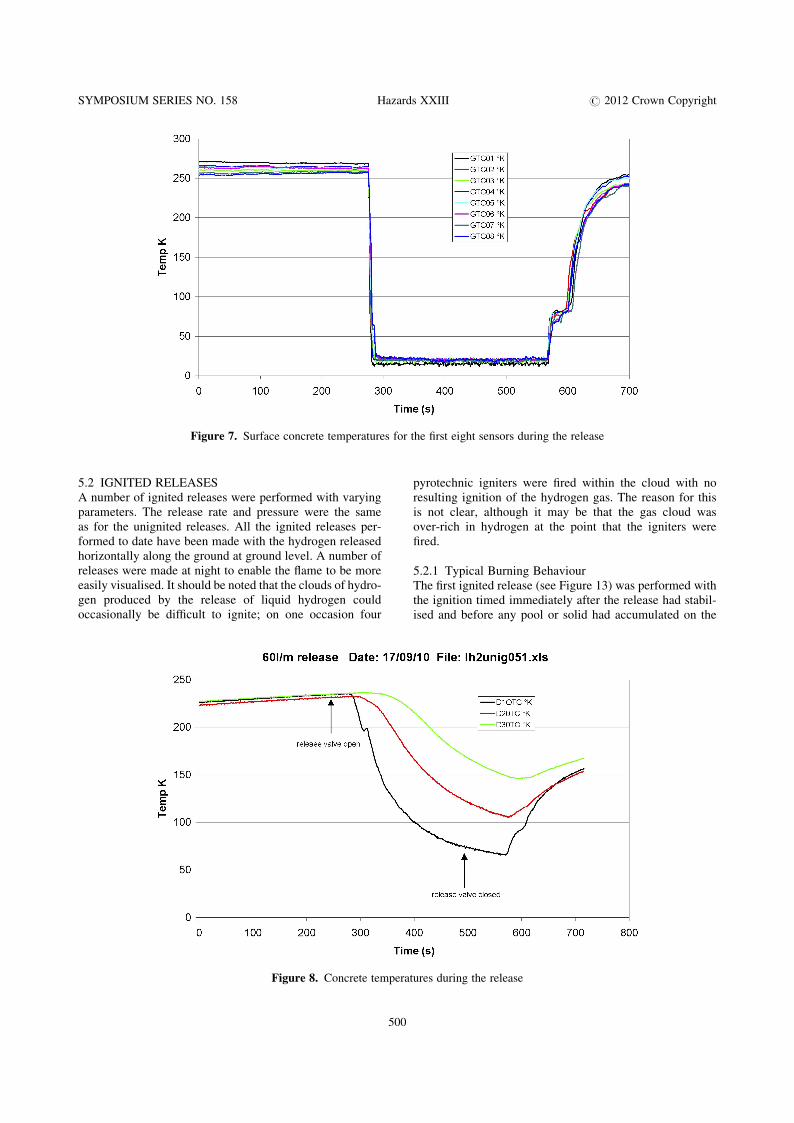
The thermocouple measurements taken in contactwith the ground during the release are shown in Figure 7.These show a degree of sub-cooling is occurring as thehydrogen is released and evaporates, with temperatures aslow as 16 K being recorded. In addition steps are evidentin the temperature traces as the temperature increases afterthe release has ended. This is indicative of the meltingand boiling of the condensed air.
The temperatures typically recorded in the concretelayer underneath the release point are shown in Figure 8at depths of 10, 20 and 30 mm.
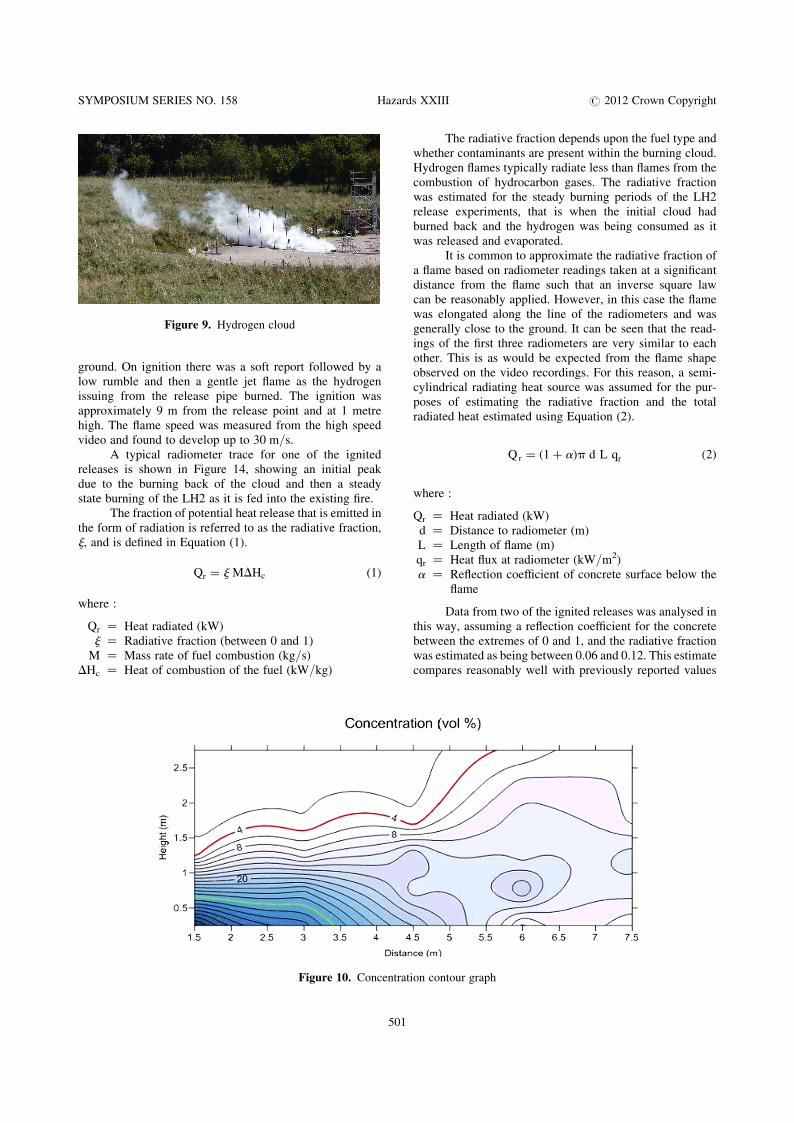
The cloud of hydrogen vapour is visible during therelease due to condensation of water within the cloud. Aphotograph showing a typical hydrogen cloud formed by arelease is shown in Figure 9.
A concentration contour graph is shown in Figure 10representing a snapshot of experimental data from a typicalhorizontal release at ground level. The graph was generatedusing measured hydrogen concentration data at variousheights and distances from the release point. The red linerepresents the 4% concentration contour (LFL) and thegreen line the 30% concentration contour (stoichiometric).The graph gives an estimate of hydrogen concentrations ata specific time during the release when the wind directionwas such that the hydrogen cloud passed through thesensors.
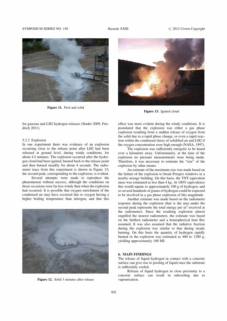
A photograph of the pool of liquid produced during arelease is shown at Figure 11. A solid deposit can also beseen close to the release point. A close up photograph ofthe solid deposit can be seen in Figure 12.
This solid persisted for some time after the releaseappearing to co-exist with a boiling pool of liquid. Thesolid deposit appeared to sublime rather than melt, possiblydue to the relatively close melting and boiling points com-pared to ambient temperature.
After one of the tests an attempt was made to ignitethe vapour above the solid deposit. The deposit ignitedand a vigorous flame ensued, but no explosion occurred.
Initial thoughts are that the solid deposit is a mixtureof solid nitrogen and oxygen with some liquid hydrogentrapped within the matrix similar to that observed whenbutane forms hydrates with water (Allen 2000).
Figure 6. Radiometer positions on test pad
SYMPOSIUM SERIES NO. 158 Hazards XXIII # 2012 Crown Copyright
499
5.2 IGNITED RELEASESA number of ignited releases were performed with varyingparameters. The release rate and pressure were the sameas for the unignited releases. All the ignited releases per-formed to date have been made with the hydrogen releasedhorizontally along the ground at ground level. A number ofreleases were made at night to enable the flame to be moreeasily visualised. It should be noted that the clouds of hydro-gen produced by the release of liquid hydrogen couldoccasionally be difficult to ignite; on one occasion four
pyrotechnic igniters were fired within the cloud with noresulting ignition of the hydrogen gas. The reason for thisis not clear, although it may be that the gas cloud wasover-rich in hydrogen at the point that the igniters werefired.
5.2.1 Typical Burning BehaviourThe first ignited release (see Figure 13) was performed withthe ignition timed immediately after the release had stabil-ised and before any pool or solid had accumulated on the
Figure 7. Surface concrete temperatures for the first eight sensors during the release
Figure 8. Concrete temperatures during the release
SYMPOSIUM SERIES NO. 158 Hazards XXIII # 2012 Crown Copyright
500
ground. On ignition there was a soft report followed by alow rumble and then a gentle jet flame as the hydrogenissuing from the release pipe burned. The ignition wasapproximately 9 m from the release point and at 1 metrehigh. The flame speed was measured from the high speedvideo and found to develop up to 30 m/s.
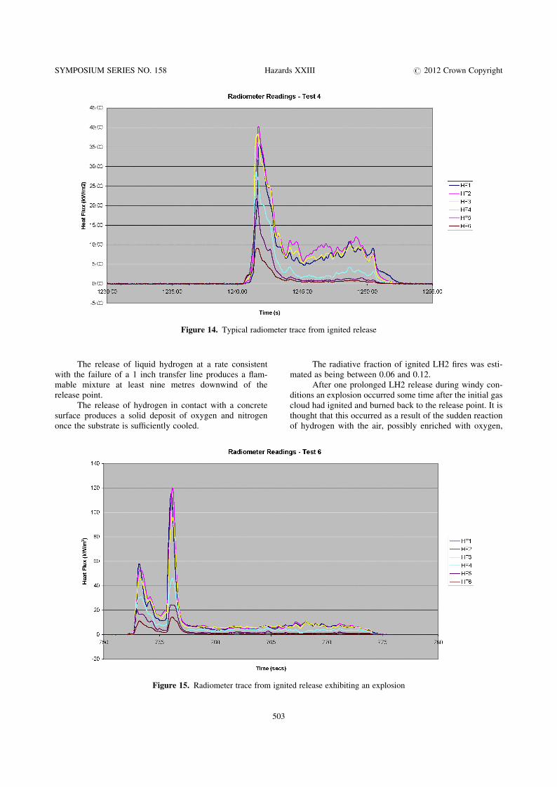
A typical radiometer trace for one of the ignitedreleases is shown in Figure 14, showing an initial peakdue to the burning back of the cloud and then a steadystate burning of the LH2 as it is fed into the existing fire.
The fraction of potential heat release that is emitted inthe form of radiation is referred to as the radiative fraction,j, and is defined in Equation (1).
Qr = j MDHc (1)
where :
Qr ¼ Heat radiated (kW)j ¼ Radiative fraction (between 0 and 1)
M ¼ Mass rate of fuel combustion (kg/s)DHc ¼ Heat of combustion of the fuel (kW/kg)
The radiative fraction depends upon the fuel type andwhether contaminants are present within the burning cloud.Hydrogen flames typically radiate less than flames from thecombustion of hydrocarbon gases. The radiative fractionwas estimated for the steady burning periods of the LH2release experiments, that is when the initial cloud hadburned back and the hydrogen was being consumed as itwas released and evaporated.
It is common to approximate the radiative fraction ofa flame based on radiometer readings taken at a significantdistance from the flame such that an inverse square lawcan be reasonably applied. However, in this case the flamewas elongated along the line of the radiometers and wasgenerally close to the ground. It can be seen that the read-ings of the first three radiometers are very similar to eachother. This is as would be expected from the flame shapeobserved on the video recordings. For this reason, a semi-cylindrical radiating heat source was assumed for the pur-poses of estimating the radiative fraction and the totalradiated heat estimated using Equation (2).
Q r = (1 + a)p d L qr (2)
where :
Qr ¼ Heat radiated (kW)d ¼ Distance to radiometer (m)L ¼ Length of flame (m)qr ¼ Heat flux at radiometer (kW/m2)a ¼ Reflection coefficient of concrete surface below the
flame
Data from two of the ignited releases was analysed inthis way, assuming a reflection coefficient for the concretebetween the extremes of 0 and 1, and the radiative fractionwas estimated as being between 0.06 and 0.12. This estimatecompares reasonably well with previously reported values
Figure 10. Concentration contour graph
Figure 9. Hydrogen cloud
SYMPOSIUM SERIES NO. 158 Hazards XXIII # 2012 Crown Copyright
501
for gaseous and LH2 hydrogen releases (Studer 2009, Frie-drich 2011).
5.2.2 ExplosionIn one experiment there was evidence of an explosionoccurring close to the release point after LH2 had beenreleased at ground level, during windy conditions, forabout 4.5 minutes. The explosion occurred after the hydro-gen cloud had been ignited, burned back to the release pointand then burned steadily for about 4 seconds. The radio-meter trace from this experiment is shown in Figure 15;the second peak, corresponding to the explosion, is evident.
Several attempts were made to reproduce thephenomenon without success, although the conditions onthose occasions were far less windy than when the explosionhad occurred. It is possible that oxygen enrichment of thecondensed air may have occurred due to oxygen having ahigher boiling temperature than nitrogen, and that this
effect was more evident during the windy conditions. It ispostulated that the explosion was either a gas phaseexplosion resulting from a sudden release of oxygen fromthe solid due to a rapid phase change, or even a rapid reac-tion within the condensed slurry of solidified air and LH2 ifthe oxygen concentration were high enough (NASA, 1997).
The explosion was sufficiently energetic to be heardover a kilometre away. Unfortunately, at the time of theexplosion no pressure measurements were being made.Therefore, it was necessary to estimate the “size” of theexplosion by other means.
An estimate of the maximum size was made based onthe failure of the explosion to break Perspex windows in anearby storage building. On this basis, the TNT equivalentmass was estimated as less than 4 kg. At 100% equivalencethis would equate to approximately 100 g of hydrogen, andso several hundreds of grams of hydrogen could be expectedto be involved in a gas phase explosion of this magnitude.
Another estimate was made based on the radiometerresponse during the explosion (that is the area under thesecond peak represents the total energy per m2 received atthe radiometer). Since the resulting explosion almostengulfed the nearest radiometers, the estimate was basedon the furthest radiometer and a hemispherical heat fluxassumed. It was also assumed that the radiative fractionduring the explosion was similar to that during steadyburning. On this basis the quantity of hydrogen rapidlyburned in the explosion was estimated as 400 to 1200 g,yielding approximately 100 MJ.
6. MAIN FINDINGSThe release of liquid hydrogen in contact with a concretesurface can give rise to pooling of liquid once the substrateis sufficiently cooled.
Release of liquid hydrogen in close proximity to aconcrete surface can result in subcooling due tovapourisation.
Figure 13. Ignited cloud
Figure 12. Solid 3 minutes after release
Figure 11. Pool and solid
SYMPOSIUM SERIES NO. 158 Hazards XXIII # 2012 Crown Copyright
502
The release of liquid hydrogen at a rate consistentwith the failure of a 1 inch transfer line produces a flam-mable mixture at least nine metres downwind of therelease point.
The release of hydrogen in contact with a concretesurface produces a solid deposit of oxygen and nitrogenonce the substrate is sufficiently cooled.
The radiative fraction of ignited LH2 fires was esti-mated as being between 0.06 and 0.12.
After one prolonged LH2 release during windy con-ditions an explosion occurred some time after the initial gascloud had ignited and burned back to the release point. It isthought that this occurred as a result of the sudden reactionof hydrogen with the air, possibly enriched with oxygen,
Figure 14. Typical radiometer trace from ignited release
Figure 15. Radiometer trace from ignited release exhibiting an explosion
SYMPOSIUM SERIES NO. 158 Hazards XXIII # 2012 Crown Copyright
503

that was condensed on the ground. It is not clear whether thereaction took place in the gaseous or condensed phase.
The quantity of hydrogen involved in the explosionhas been estimated at between 400 g and 1200 g (yieldingapproximately 100 MJ).
REFERENCES“Characteristics of impinging flashing jets”, Allen, J.T., HSL
report FS/00/02, 2000.
“Experimental results from fast 15000-gallon LH2 spills”,
Chirivella, J.E. and Witkofski, R.D., AIChE Symposium
Series No. 251, Vol. 82, 1986.
“The molar Volume (Density) of Solid Oxygen in Equilibrium
with Vapor”, Roder, H.M., J.Phys.Chem.Ref. Data, Vol. 7,
No. 3, 1978.
“Properties of large-scale methane/hydrogen jet fires”, Studer,
E. et al., International Journal of Hydrogen Energy 34
(2009).
“Ignition and heat radiation of cryogenic hydrogen jets”, Frie-
drich, A. et al., 4th International Conference on Hydrogen
Safety, 2011.
NASA document NSS 1740.16 : “Hydrogen and Hydrogen
Systems, Guidelines for.
Hydrogen System Design, Materials Selection, Operations,
Storage, and Transportation”, 1997.
SYMPOSIUM SERIES NO. 158 Hazards XXIII # 2012 Crown Copyright
504