Embed Size (px)
Citation preview
Experimental studies of Bose-Einsteincondensation
Dallin S. Durfee and Wolfgang Ketterle
Department of Physics and Research Laboratory of Electronics, Massachusetts Institute of Technology, Cambridge,MA 02139
Abstract: We describe several experimental studies of Bose-Einsteincondensation in a dilute gas of sodium atoms. These include studies of staticand dynamic behavior of the condensate, and of its coherence properties.Ó1998 Optical Society of AmericaOCIS codes: (020.0020) Atomic and molecular physics; (020.7010) Trapping; (999.9999)Bose-Einstein condensation
References and links
1. M.H. Anderson, J.R. Ensher, M.R. Matthews, C.E. Wieman, and E.A. Cornell, "Observation of Bose-Einstein Condensation in a Dilute Atomic Vapor", Science 269, 198 (1995).
2. K.B. Davis, M.-O. Mewes, M.R. Andrews, N.J. van Druten, D.S. Durfee, D.M. Kurn, and W. Ketterle,"Bose-Einstein condensation in a gas of sodium atoms", Phys. Rev. Lett. 75, 3969 (1995).
3. C.C. Bradley, C.A. Sackett, and R.G. Hulet, "Bose-Einstein Condensation of Lithium: Observation ofLimited Condensate Number", Phys. Rev. Lett. 78, 985 (1997).
4. K. Huang, "Imperfect Bose Gas", in Studies in Statistical Mechanics, vol. II, edited by J. de Boer and G.E.Uhlenbeck (North-Holland, Amsterdam, 1964) p. 3.
5. A. Griffin, D.W. Snoke, and S. Stringari (editors), Bose-Einstein Condensation (Cambridge UniversityPress, Cambridge, 1995).
6. K. Huang, Statistical Mechanics, second edition (Wiley, New York, 1987).7. M.-O. Mewes, M.R. Andrews, N.J. van Druten, D.M. Kurn, D.S. Durfee, and W. Ketterle, "Bose-Einstein
condensation in a tightly confining dc magnetic trap", Phys. Rev. Lett. 77, 416 (1996).8. Background information for the 1997 Nobel prize in physics for laser cooling,
http://www.nobel.se/announcement-97/phyback97.html 9. Links to research groups with atom traps, http://www-atoms.physics.wisc.edu/OtherSites.html 10. C.G. Townsend, N.J. van Druten, M.R. Andrews, D.S. Durfee, D.M. Kurn, M.-O. Mewes, and W.
Ketterle, "Bose-Einstein condensation of a weakly-interacting gas", in Ultracold Atoms and Bose-Einstein-Condensation, 1996, K. Burnett, ed., OSA Trends in Optics and Photonics Series, Vol. 7 (Optical Societyof America, Washington D.C., 1996) p. 2.
11. Indirect evidence was reported in: C.C. Bradley, C.A. Sackett, J.J. Tollet, and R.G. Hulet, "Evidence ofBose-Einstein Condensation in an Atomic Gas with Attractive Interactions", Phys. Rev. Lett. 75, 1687(1995).
12. W. Ketterle, M.R. Andrews, K.B. Davis, D.S. Durfee, D.M. Kurn, M.-O. Mewes, and N.J. van Druten,"Bose-Einstein condensation of ultracold atomic gases", Phys. Scr. T66, 31 (1996).
13. BEC home page of the Georgia Southern University, http://amo.phy.gasou.edu/bec.html 14. Home page of our group, http://amo.mit.edu/~bec 15. N.J. van Druten, C.G. Townsend, M.R. Andrews, D.S. Durfee, D.M. Kurn, M.-O. Mewes, and W.
Ketterle, "Bose-Einstein condensates - a new form of quantum matter", Czech. J. Phys. 46 (S6), 3077(1996).
16. D.S. Jin, J.R. Ensher, M.R. Matthews, C.E. Wieman, and E.A. Cornell, "Quantitative Studies of Bose-Einstein Condensation in a Dilute Atomic Vapor", Czech. J. Phys. 46 (S6), 3070 (1996).
17. C.A. Sackett, C.C. Bradley, M. Welling, and R.G. Hulet, "Bose-Einstein Condensation of Lithium", Braz. J.Phys. 27, 154 (1997).
18. N.P. Proukakis, K. Burnett, M. Edwards, R.J. Dodd, and C.W. Clark, "Theory of Bose-Einstein condensedtrapped atoms", in Ultracold Atoms and Bose-Einstein-Condensation, 1996, K. Burnett, ed., OSA Trends inOptics and Photonics Series, Vol. 7 (Optical Society of America, Washington D.C., 1996) p. 14.
19. A. Einstein, "Quantentheorie des einatomigen idealen Gases. II", Sitzungsber. K. Preuss. Akad. Wiss. Phys.Math. Kl, 3 (1925).
#3983 - $15.00 US Received November 10, 1998
(C) 1998 OSA 13 April 1998 / Vol. 2, No. 8 / OPTICS EXPRESS 299
20. M.R. Andrews, M.-O. Mewes, N.J. van Druten, D.S. Durfee, D.M. Kurn, and W. Ketterle, "Direct, Non-Destructive Observation of a Bose Condensate", Science 273, 84 (1996).
21. M.R. Andrews, D.M. Kurn, H.-J. Miesner, D.S. Durfee, C.G. Townsend, S. Inouye, and W. Ketterle,"Propagation of sound in a Bose-Einstein condensate", Phys. Rev. Lett. 79, 553 (1997).
22. E. Hecht, Optics, 2nd edition (Addison-Wesley, Reading, 1989).23. Y. Castin and R. Dum, "Bose-Einstein condensation in time dependent traps", Phys. Rev. Lett. 77, 5315
(1996).24. A. Griffin, Excitations in a Bose-condensed liquid (Cambridge University Press, Cambridge, 1993).25. D.S. Jin, J.R. Ensher, M.R. Matthews, C.E. Wieman, and E.A. Cornell, "Collective Excitations of a Bose-
Einstein Condensate in a Dilute Gas", Phys. Rev. Lett. 77, 420 (1996).26. M.-O. Mewes, M.R. Andrews, N.J. van Druten, D.M. Kurn, D.S. Durfee, C.G. Townsend, and W.
Ketterle, "Collective Excitations of a Bose-Einstein condensate in a Magnetic Trap", Phys. Rev. Lett. 77,988 (1996).
27. S. Stringari, "Collective excitations of a trapped Bose-condensed gas", Phys. Rev. Lett. 77, 2360 (1996).28. D. Stamper-Kurn, H.-J. Miesner, S. Inouye, M.R. Andrews, and W. Ketterle, "Excitations of a Bose-
Einstein Condensate at Non-Zero Temperature: A Study of Zeroth, First, and Second Sound", Phys. Rev.Lett. (1998), submitted.
29. D.S. Jin, M.R. Matthews, J.R. Ensher, C.E. Wieman, and E.A. Cornell, "Temperature-Dependent Dampingand Frequency Shifts in Collective Excitations of a Dilute Bose-Einstein Condensate", Phys. Rev. Lett. 78,764 (1997).
30. H.M. Wiseman, "Defining the (atom) laser", Phys. Rev. A 56, 2068 (1997).31. D. Kleppner, Phys. Today, Aug. 1997, p. 11; Jan. 1998, p. 90.32. M.-O. Mewes, M.R. Andrews, D.M. Kurn, D.S. Durfee, C.G. Townsend, and W. Ketterle, "Output
coupler for Bose-Einstein condensed atoms", Phys. Rev. Lett. 78, 582 (1997).33. P.W. Anderson, "Measurement in Quantum Theory and the Problem of Complex Systems", in The Lesson
of Quantum Theory, J.d. Boer, E. Dal, and O. Ulfbeck, ed. (Elsevier, Amsterdam, 1986) p. 23.34. J. Javanainen and S.M. Yoo, "Quantum Phase of a Bose-Einstein Condensate with an Arbitrary Number of
Atoms", Phys. Rev. Lett. 76, 161 (1996).35. M.R. Andrews, C.G. Townsend, H.-J. Miesner, D.S. Durfee, D.M. Kurn, and W. Ketterle, "Observation
of interference between two Bose condensates", Science 275, 637 (1997).36. W. Ketterle and H.-J. Miesner, "Coherence properties of Bose-Einstein condensates and atom lasers",
Phys. Rev. A 56, 3291 (1997).37. E.A. Burt, R.W. Ghrist, C.J. Myatt, M.J. Holland, E.A. Cornell, and C.E. Wieman, "Coherence,
Correlations, and Collisions: What One Learns About Bose-Einstein Condensates form Their Decay",Phys. Rev. Lett. 79, 337 (1997).
38. P. Navez, D. Bitouk, M. Gajda, Z. Idziaszek, and K. Rzazewski, "Fourth Statistical Ensemble for theBose-Einstein Condensate", Phys. Rev. Lett. 79, 1789 (1997).
39. P.A. Ruprecht, M.J. Holland, K. Burnett, and M. Edwards, "Time-dependent solution of the nonlinearSchr�dinger equation for Bose-condensed trapped neutral atoms", Phys. Rev. A 51, 4704 (1995).
40. Y. Kagan, G.V. Shlyapnikov, and J.T.M. Walraven, "Bose-Einstein condensation in trapped atomicgases", Phys. Rev. Lett. 76, 2670 (1996).
1. Introduction
The recent observation of Bose-Einstein condensation (BEC) in alkali vapors [1-3] was therealization of many long-standing goals: (1) To cool neutral atoms into the ground state ofthe system, thus exerting ultimate control over the motion and position of atoms limitedonly by HeisenbergÕs uncertainty relation. (2) To generate a coherent sample of atoms alloccupying the same quantum state (this was used to realize a rudimentary atom laser, a devicewhich generates coherent matter waves). (3) To produce degenerate quantum gases withproperties quite different from the quantum liquids He-3 and He-4. This provides a testingground for many-body theories of the dilute Bose gas which were developed many decadesago but never tested experimentally[4]. BEC of dilute atomic gases or of excitons is amacroscopic quantum phenomena with similarities to superfluidity, superconductivity and thelaser phenomenon[5].
Bose-Einstein condensation is based on the wave nature of particles, which is at theheart of quantum mechanics. In a simplified picture, atoms in a gas may be regarded asquantum-mechanical wavepackets which have an extent on the order of a thermal de Brogliewavelength (the position uncertainty associated with the thermal momentum distribution).The lower the temperature, the longer is the de Broglie wavelength. When atoms are cooledto the point where the thermal de Broglie wavelength is comparable to the interatomicseparation, then the atomic wavepackets ÒoverlapÓ and the indistinguishability of particles
#3983 - $15.00 US Received November 10, 1998
(C) 1998 OSA 13 April 1998 / Vol. 2, No. 8 / OPTICS EXPRESS 300
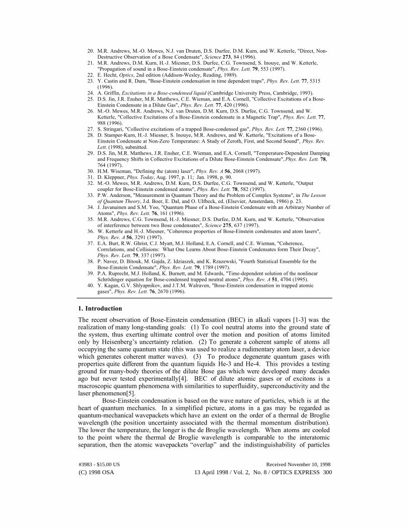
becomes important (Fig. 1). Bosons undergo a phase transition and form a Bose-Einsteincondensate, a dense and coherent cloud of atoms all occupying the same quantum mechanicalstate[6]. The relation between the transition temperature and the peak atomic density n canbe simply expressed as nldB
3= 2.612, where the thermal de Broglie wavelength is defined asldB = (2ph2/mkBT)1/2 and m is the mass of the atom.
High Temperature T:
LowTemperature T:
T=Tcrit:Bose-EinsteinCondensation
T=0:Pure Bose
condensate
dBDe Broglie wavelength
dB=h/mv T-1/2
v
thermal velocity vdensity d-3
d
dB d
"Billiard balls"
"Wave packets"
"Matter wave overlap"
"Giant matter wave"
Fig. 1. Criterion for Bose-Einstein condensation. At high temperatures, a weakly interacting gascan be treated as a system of Òbilliard ballsÓ. In a simplified quantum description, the atoms canbe regarded as wavepackets with an extension Dx, approximately given by HeisenbergÕsuncertainty relation Dx= h/Dp, where Dp denotes the width of the thermal momentum distribution.Dx is approximately equal to the thermal de Broglie wavelength ldB, the matter wavelength for anatom moving with the thermal velocity. When the gas is cooled down the de Broglie wavelengthincreases. At the BEC transition temperature, ldB becomes comparable to the distance betweenatoms, and the Bose condensates forms which is characterized by a macroscopic population ofthe ground state of the system. As the temperature approaches absolute zero, the thermal clouddisappears leaving a pure Bose condensate.
The realization of Bose-Einstein condensation requires techniques to cool gases tosub-microkelvin temperatures and atom traps to confine them at high density and keep themaway from the hot walls of the vacuum chamber. Over the last 15 years, such techniques havebeen developed in the atomic physics and low-temperature communities[5]. The MITexperiment uses a multistage process to cool hot sodium vapor down to temperatures wherethe atoms form a condensate[2,7]. A beam of sodium atoms is emitted from an atomic beamoven at a density of about 1014 atoms per cm3, similar to the eventual density of thecondensate. The gas is cooled by nine orders of magnitude from 600K to 1mK by firstslowing the atomic beam, then by optical trapping and laser cooling the atoms[8,9], andfinally by magnetic trapping and evaporative cooling[10].
The first experimental demonstrations of BEC [1-3, 11] were followed by severalexperimental studies and numerous theoretical papers (See Refs. [10, 12-18] for reviews). Werefer to our previous review[10] for the historical context, for an account of the developmentswhich led to BEC, and for an overview of the techniques used to realize BEC. In this paper,we summarize some experimental studies of Bose-Einstein condensation and illustrate themwith animations of experimental results. These illustrations display another important aspect
#3983 - $15.00 US Received November 10, 1998
(C) 1998 OSA 13 April 1998 / Vol. 2, No. 8 / OPTICS EXPRESS 301
of Bose-Einstein condensation. Since a Bose condensate is characterized by a macroscopicpopulation of a single quantum state, the imaging of condensates and their dynamicalbehavior constitutes a dramatic visualization of quantum-mechanical wavefunctions and givewavefunctions a new level of reality. The animations and many figures in this paper have notbeen published before, whereas all experimental results have been previously reported in moretechnical papers.
2. Identifying the Bose-Einstein condensate
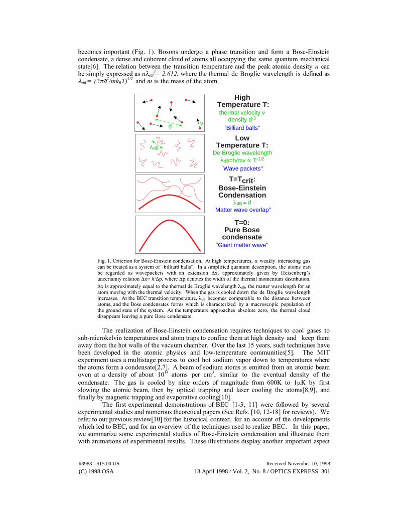
Bose-Einstein condensation was achieved by evaporatively cooling a gas of magneticallytrapped atoms to the transition temperature. In the first observations[1,2], four features wereused to identify the formation of a Bose-Einstein condensate :(1) The sudden increase in the density of the cloud.(2) The sudden appearance of a bimodal cloud consisting of a diffuse normal component and adense core (the condensate).(3) The velocity distribution of the condensate was anisotropic in contrast to the isotropicexpansion of the normal (non-condensed) component.(4) The good agreement between the predicted and measured transition temperatures.
The first three points are illustrated in Fig. 2. It shows time-of-flight pictures ofexpanding clouds released from the magnetic trap by suddenly switching off the trap. Theseimages, taken during our second data run which produced Bose-Einstein condensation, wererecorded by illuminating the cloud with resonant laser light and imaging the shadow of thecloud onto a CCD camera[2].
Fig. 2. Observation of Bose-Einstein condensation by absorption imaging. Shown is absorption vs.two spatial dimensions. The Bose-Einstein condensate is characterized by its slow expansionobserved after 6 msec time of flight. The left picture shows an expanding cloud cooled to justabove the transition point; middle: just after the condensate appeared; right: after furtherevaporative cooling has left an almost pure condensate. The width of the images is 1.0 mm. Thetotal number of atoms at the phase transition is about 7x10⁵, the temperature at the transition pointis 2 mK.
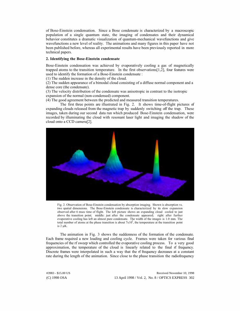
The animation in Fig. 3 shows the suddenness of the formation of the condensate.Each frame required a new loading and cooling cycle. Frames were taken for various finalfrequencies of the rf sweep which controlled the evaporative cooling process. To a very goodapproximation, the temperature of the cloud is linearly related to the final rf frequency.Discrete frames were interpolated in such a way that the rf frequency decreases at a constantrate during the length of the animation. Since close to the phase transition the radiofrequency
#3983 - $15.00 US Received November 10, 1998
(C) 1998 OSA 13 April 1998 / Vol. 2, No. 8 / OPTICS EXPRESS 302
was swept linearly in time, Fig. 3 represents the temporal dynamics of the cooling processduring the last fraction of a second (the whole evaporation process took only seven seconds).
Fig. 3. Formation of a Bose-Einstein condensate. Two-dimensional probe absorption images,after 6 msec time of flight, show the sharpness of the phase transition. This sequence includes thethree images of Fig. 2. The evaporative cooling was induced by an externally applied rf field.As the final rf frequency (labeled on the plots) was lowered, lower temperatures and higherphase space densities were reached. The cloud at the start of the animation had a temperature ofabout 5 mK. Above the phase transition (frequency >700 kHz) the clouds expanded spherically,as expected for a normal thermal distribution. As the frequency was reduced, the sphericalcloud shrank in size, due to the lower temperatures reached. Below the transition point(frequency <700 kHz, 2 mK) an elliptical core appeared, which is the signature of thecondensate. As the frequency was lowered the spherical part became invisible, corresponding toa pure condensate. Finally, when the threshold for evaporation reached the bottom of the trap(around 300 kHz), the condensate itself was lost by evaporation. Note that the color scale herehas been chosen to represent optical density (OD) instead of absorption (A), as used in the otherimages. The two are related by OD=-ln(1-A). The rf frequency displayed in the animationchanges when a new original frame is displayed and stays constant when interpolated frames areshown. The size of the frame is 1.1 by 1.6 mm.
Fig. 4 shows the formation of the condensate observed by directly imaging thetrapped condensate. One can regard Figures 2 and 3 as showing condensation in energy (ormomentum space), whereas Fig. 4 demonstrates that condensation also takes place inconfiguration space. BEC is always a condensation phenomenon into the lowest energy state.In a homogeneous gas, however, the ground state has the same spatial extension as theexcited state - therefore BEC is only a condensation in momentum space. In contrast, in aharmonic oscillator potential the ground state has the smallest extension, and one can observeBEC in configuration space. In his second paper on quantum statistics, Einstein used thenotion of the saturated ideal gas to describe the condensation phenomenon[19]. Fig. 4 showsdirectly the ÒdropletÓ formation when the atomic vapor reaches Òquantum saturation.Ó
Spatial images like the one in Fig. 4 are not taken by absorption imaging, but bydispersive imaging[20, 21]. The reason for this is that the trapped condensates are verydense. If the image were to be taken on resonance, the probe light would be fully absorbed,and close to resonance, it would be strongly refracted due to the index of refraction of thetrapped cloud. A solution is to go far off resonance (in our case about 350 half linewidths)where absorption is negligible and dispersion is small, and use imaging techniques which
#3983 - $15.00 US Received November 10, 1998
(C) 1998 OSA 13 April 1998 / Vol. 2, No. 8 / OPTICS EXPRESS 303
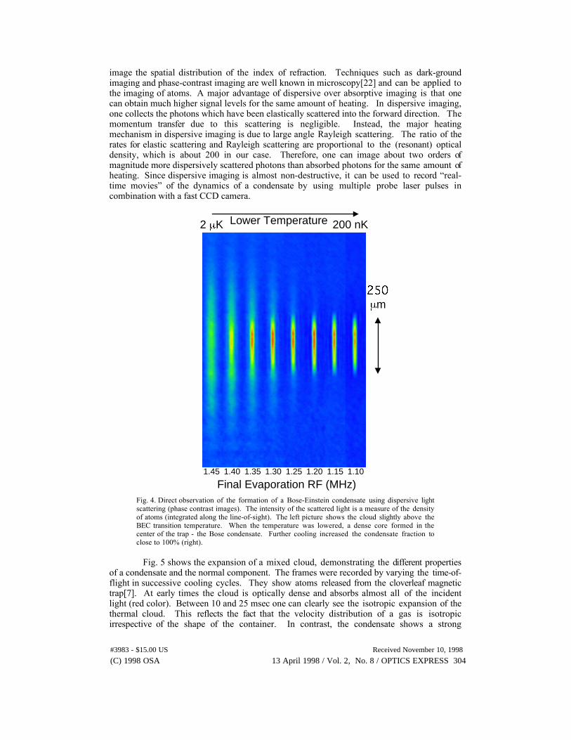
image the spatial distribution of the index of refraction. Techniques such as dark-groundimaging and phase-contrast imaging are well known in microscopy[22] and can be applied tothe imaging of atoms. A major advantage of dispersive over absorptive imaging is that onecan obtain much higher signal levels for the same amount of heating. In dispersive imaging,one collects the photons which have been elastically scattered into the forward direction. Themomentum transfer due to this scattering is negligible. Instead, the major heatingmechanism in dispersive imaging is due to large angle Rayleigh scattering. The ratio of therates for elastic scattering and Rayleigh scattering are proportional to the (resonant) opticaldensity, which is about 200 in our case. Therefore, one can image about two orders ofmagnitude more dispersively scattered photons than absorbed photons for the same amount ofheating. Since dispersive imaging is almost non-destructive, it can be used to record Òreal-time moviesÓ of the dynamics of a condensate by using multiple probe laser pulses incombination with a fast CCD camera.
1.40 1.151.201.251.301.351.45 1.10
Final Evaporation RF (MHz)
m
Lower Temperature2 K 200 nK
Fig. 4. Direct observation of the formation of a Bose-Einstein condensate using dispersive lightscattering (phase contrast images). The intensity of the scattered light is a measure of the densityof atoms (integrated along the line-of-sight). The left picture shows the cloud slightly above theBEC transition temperature. When the temperature was lowered, a dense core formed in thecenter of the trap - the Bose condensate. Further cooling increased the condensate fraction toclose to 100% (right).
Fig. 5 shows the expansion of a mixed cloud, demonstrating the different propertiesof a condensate and the normal component. The frames were recorded by varying the time-of-flight in successive cooling cycles. They show atoms released from the cloverleaf magnetictrap[7]. At early times the cloud is optically dense and absorbs almost all of the incidentlight (red color). Between 10 and 25 msec one can clearly see the isotropic expansion of thethermal cloud. This reflects the fact that the velocity distribution of a gas is isotropicirrespective of the shape of the container. In contrast, the condensate shows a strong
#3983 - $15.00 US Received November 10, 1998
(C) 1998 OSA 13 April 1998 / Vol. 2, No. 8 / OPTICS EXPRESS 304
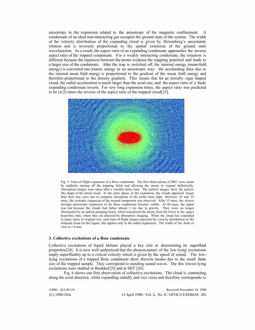
anisotropy in the expansion related to the anisotropy of the magnetic confinement. Acondensate of an ideal non-interacting gas occupies the ground state of the system. The widthof the velocity distribution of the expanding cloud is given by HeisenbergÕs uncertaintyrelation and is inversely proportional to the spatial extension of the ground statewavefunction. As a result, the aspect ratio of an expanding condensate approaches the inverseaspect ratio of the trapped condensate. For a weakly interacting condensate, the situation isdifferent because the repulsion between the atoms weakens the trapping potential and leads toa larger size of the condensate. After the trap is switched off, the internal energy (mean-fieldenergy) is converted into kinetic energy in an anisotropic way: the accelerating force due tothe internal mean field energy is proportional to the gradient of the mean field energy andtherefore proportional to the density gradient. This means that for an initially cigar shapedcloud, the radial acceleration is much larger than the axial one, and the aspect ratio of a freelyexpanding condensate inverts. For very long expansion times, the aspect ratio was predictedto be (p/2) times the inverse of the aspect ratio of the trapped cloud[23].
Fig. 5. Time-of-flight expansion of a Bose condensate. The first observations of BEC were madeby suddenly turning off the trapping fields and allowing the atoms to expand ballistically.Absorption images were taken after a variable delay time. The earliest images show the pencil-like shape of the initial cloud. In the early phase of the expansion, the clouds appeared largerthan their true sizes due to complete absorption of the probe laser light. Between 10 and 25msec, the isotropic expansion of the normal component was observed. After 15 msec, the slowerstrongly anisotropic expansion of the Bose condensate became visible. At 60 msec, the signalwas lost because the clouds had fallen almost 2 cm due to gravity. They were no longerilluminated by an optical pumping beam, which transferred the atoms from the lower to the upperhyperfine state, where they are detected by absorption imaging. When the cloud has expandedto many times its original size, such time-of-flight images represent the velocity distribution of thereleased cloud (in this figure, this applies only to the radial expansion). The width of the field ofview is 1.8 mm.
3. Collective excitations of a Bose condensate
Collective excitations of liquid helium played a key role in determining its superfluidproperties[24]. It is now well understood that the phonon-nature of the low-lying excitationsimply superfluidity up to a critical velocity which is given by the speed of sound. The low-lying excitations of a trapped Bose condensate show discrete modes due to the small finitesize of the trapped sample. They correspond to standing sound waves. The few lowest-lyingexcitations were studied in Boulder[25] and at MIT [26].
Fig. 6 shows our first observation of collective excitations. The cloud is contractingalong the axial direction while expanding radially and vice versa and therefore corresponds to
#3983 - $15.00 US Received November 10, 1998
(C) 1998 OSA 13 April 1998 / Vol. 2, No. 8 / OPTICS EXPRESS 305
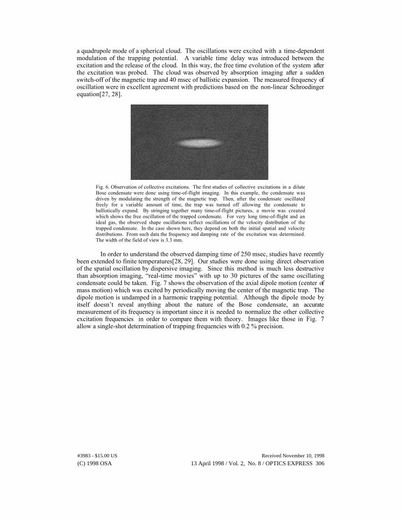
a quadrupole mode of a spherical cloud. The oscillations were excited with a time-dependentmodulation of the trapping potential. A variable time delay was introduced between theexcitation and the release of the cloud. In this way, the free time evolution of the system afterthe excitation was probed. The cloud was observed by absorption imaging after a suddenswitch-off of the magnetic trap and 40 msec of ballistic expansion. The measured frequency ofoscillation were in excellent agreement with predictions based on the non-linear Schroedingerequation[27, 28].
Fig. 6. Observation of collective excitations. The first studies of collective excitations in a diluteBose condensate were done using time-of-flight imaging. In this example, the condensate wasdriven by modulating the strength of the magnetic trap. Then, after the condensate oscillatedfreely for a variable amount of time, the trap was turned off allowing the condensate toballistically expand. By stringing together many time-of-flight pictures, a movie was createdwhich shows the free oscillation of the trapped condensate. For very long time-of-flight and anideal gas, the observed shape oscillations reflect oscillations of the velocity distribution of thetrapped condensate. In the case shown here, they depend on both the initial spatial and velocitydistributions. From such data the frequency and damping rate of the excitation was determined.The width of the field of view is 3.3 mm.
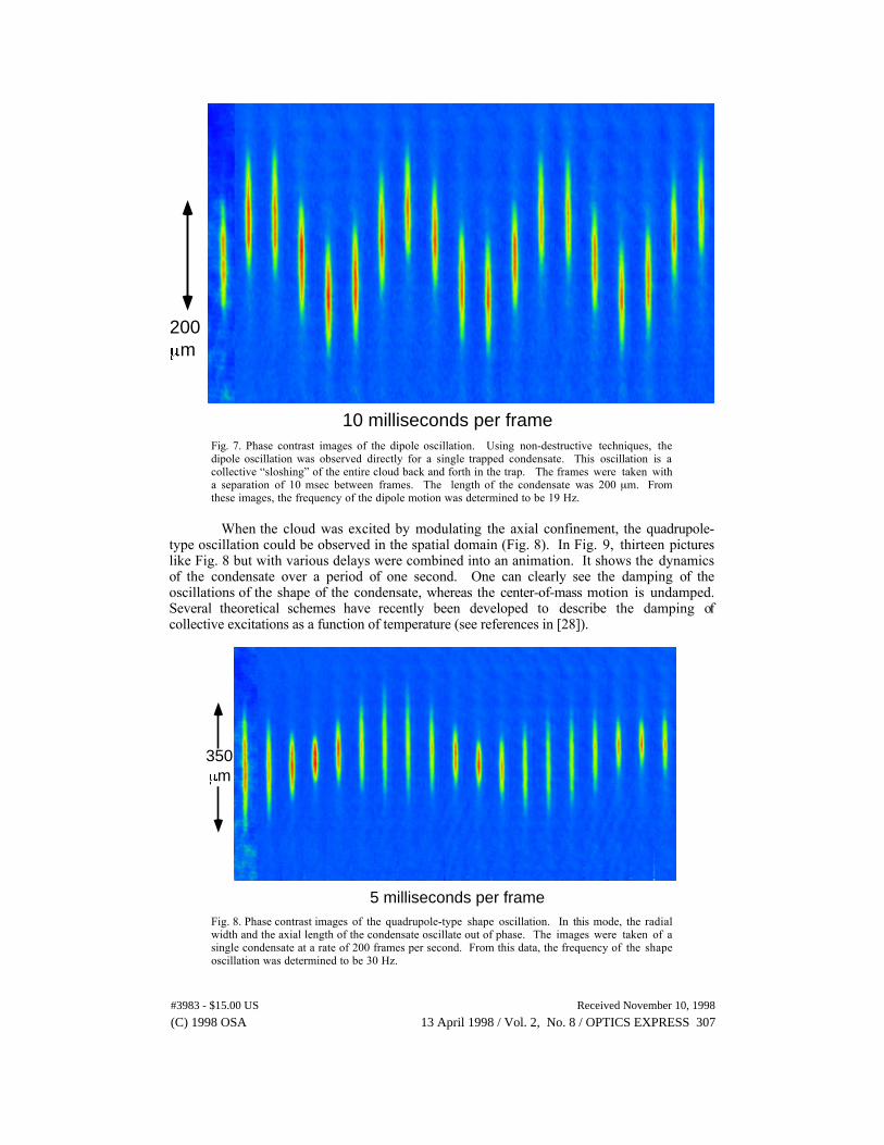
In order to understand the observed damping time of 250 msec, studies have recentlybeen extended to finite temperatures[28, 29]. Our studies were done using direct observationof the spatial oscillation by dispersive imaging. Since this method is much less destructivethan absorption imaging, Òreal-time moviesÓ with up to 30 pictures of the same oscillatingcondensate could be taken. Fig. 7 shows the observation of the axial dipole motion (center ofmass motion) which was excited by periodically moving the center of the magnetic trap. Thedipole motion is undamped in a harmonic trapping potential. Although the dipole mode byitself doesnÕt reveal anything about the nature of the Bose condensate, an accuratemeasurement of its frequency is important since it is needed to normalize the other collectiveexcitation frequencies in order to compare them with theory. Images like those in Fig. 7allow a single-shot determination of trapping frequencies with 0.2 % precision.
#3983 - $15.00 US Received November 10, 1998
(C) 1998 OSA 13 April 1998 / Vol. 2, No. 8 / OPTICS EXPRESS 306
200m
10 milliseconds per frameFig. 7. Phase contrast images of the dipole oscillation. Using non-destructive techniques, thedipole oscillation was observed directly for a single trapped condensate. This oscillation is acollective ÒsloshingÓ of the entire cloud back and forth in the trap. The frames were taken witha separation of 10 msec between frames. The length of the condensate was 200 mm. Fromthese images, the frequency of the dipole motion was determined to be 19 Hz.
When the cloud was excited by modulating the axial confinement, the quadrupole-type oscillation could be observed in the spatial domain (Fig. 8). In Fig. 9, thirteen pictureslike Fig. 8 but with various delays were combined into an animation. It shows the dynamicsof the condensate over a period of one second. One can clearly see the damping of theoscillations of the shape of the condensate, whereas the center-of-mass motion is undamped.Several theoretical schemes have recently been developed to describe the damping ofcollective excitations as a function of temperature (see references in [28]).
350m
5 milliseconds per frameFig. 8. Phase contrast images of the quadrupole-type shape oscillation. In this mode, the radialwidth and the axial length of the condensate oscillate out of phase. The images were taken of asingle condensate at a rate of 200 frames per second. From this data, the frequency of the shapeoscillation was determined to be 30 Hz.
#3983 - $15.00 US Received November 10, 1998
(C) 1998 OSA 13 April 1998 / Vol. 2, No. 8 / OPTICS EXPRESS 307
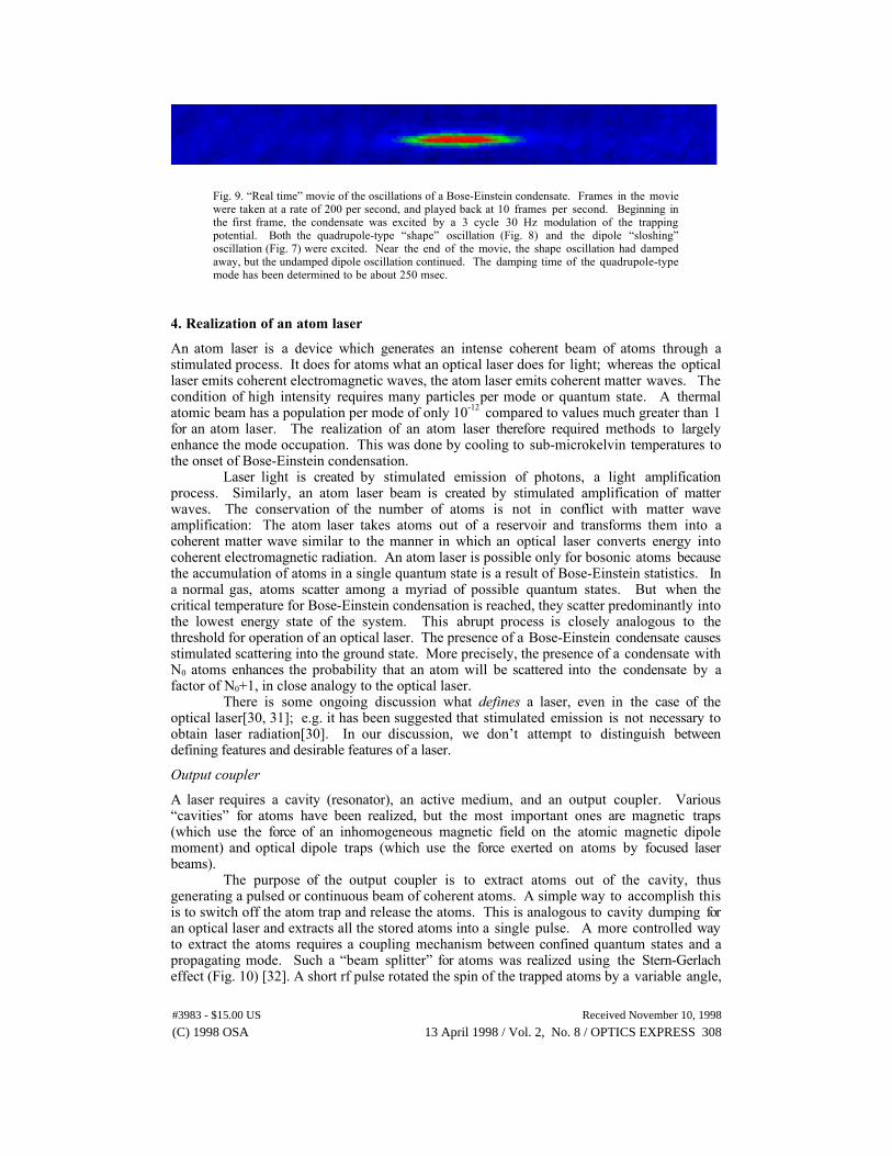
Fig. 9. ÒReal timeÓ movie of the oscillations of a Bose-Einstein condensate. Frames in the moviewere taken at a rate of 200 per second, and played back at 10 frames per second. Beginning inthe first frame, the condensate was excited by a 3 cycle 30 Hz modulation of the trappingpotential. Both the quadrupole-type ÒshapeÓ oscillation (Fig. 8) and the dipole ÒsloshingÓoscillation (Fig. 7) were excited. Near the end of the movie, the shape oscillation had dampedaway, but the undamped dipole oscillation continued. The damping time of the quadrupole-typemode has been determined to be about 250 msec.
4. Realization of an atom laser
An atom laser is a device which generates an intense coherent beam of atoms through astimulated process. It does for atoms what an optical laser does for light; whereas the opticallaser emits coherent electromagnetic waves, the atom laser emits coherent matter waves. Thecondition of high intensity requires many particles per mode or quantum state. A thermalatomic beam has a population per mode of only 10-12 compared to values much greater than 1for an atom laser. The realization of an atom laser therefore required methods to largelyenhance the mode occupation. This was done by cooling to sub-microkelvin temperatures tothe onset of Bose-Einstein condensation.
Laser light is created by stimulated emission of photons, a light amplificationprocess. Similarly, an atom laser beam is created by stimulated amplification of matterwaves. The conservation of the number of atoms is not in conflict with matter waveamplification: The atom laser takes atoms out of a reservoir and transforms them into acoherent matter wave similar to the manner in which an optical laser converts energy intocoherent electromagnetic radiation. An atom laser is possible only for bosonic atoms becausethe accumulation of atoms in a single quantum state is a result of Bose-Einstein statistics. Ina normal gas, atoms scatter among a myriad of possible quantum states. But when thecritical temperature for Bose-Einstein condensation is reached, they scatter predominantly intothe lowest energy state of the system. This abrupt process is closely analogous to thethreshold for operation of an optical laser. The presence of a Bose-Einstein condensate causesstimulated scattering into the ground state. More precisely, the presence of a condensate withN0 atoms enhances the probability that an atom will be scattered into the condensate by afactor of N0+1, in close analogy to the optical laser.
There is some ongoing discussion what defines a laser, even in the case of theoptical laser[30, 31]; e.g. it has been suggested that stimulated emission is not necessary toobtain laser radiation[30]. In our discussion, we donÕt attempt to distinguish betweendefining features and desirable features of a laser.
Output coupler
A laser requires a cavity (resonator), an active medium, and an output coupler. VariousÒcavitiesÓ for atoms have been realized, but the most important ones are magnetic traps(which use the force of an inhomogeneous magnetic field on the atomic magnetic dipolemoment) and optical dipole traps (which use the force exerted on atoms by focused laserbeams).
The purpose of the output coupler is to extract atoms out of the cavity, thusgenerating a pulsed or continuous beam of coherent atoms. A simple way to accomplish thisis to switch off the atom trap and release the atoms. This is analogous to cavity dumping foran optical laser and extracts all the stored atoms into a single pulse. A more controlled wayto extract the atoms requires a coupling mechanism between confined quantum states and apropagating mode. Such a Òbeam splitterÓ for atoms was realized using the Stern-Gerlacheffect (Fig. 10) [32]. A short rf pulse rotated the spin of the trapped atoms by a variable angle,
#3983 - $15.00 US Received November 10, 1998
(C) 1998 OSA 13 April 1998 / Vol. 2, No. 8 / OPTICS EXPRESS 308
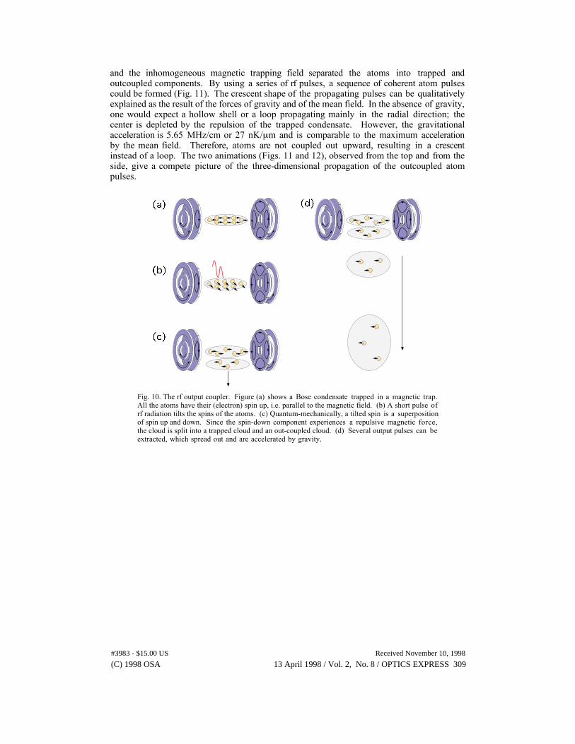
and the inhomogeneous magnetic trapping field separated the atoms into trapped andoutcoupled components. By using a series of rf pulses, a sequence of coherent atom pulsescould be formed (Fig. 11). The crescent shape of the propagating pulses can be qualitativelyexplained as the result of the forces of gravity and of the mean field. In the absence of gravity,one would expect a hollow shell or a loop propagating mainly in the radial direction; thecenter is depleted by the repulsion of the trapped condensate. However, the gravitationalacceleration is 5.65 MHz/cm or 27 nK/mm and is comparable to the maximum accelerationby the mean field. Therefore, atoms are not coupled out upward, resulting in a crescentinstead of a loop. The two animations (Figs. 11 and 12), observed from the top and from theside, give a compete picture of the three-dimensional propagation of the outcoupled atompulses.
Fig. 10. The rf output coupler. Figure (a) shows a Bose condensate trapped in a magnetic trap.All the atoms have their (electron) spin up, i.e. parallel to the magnetic field. (b) A short pulse ofrf radiation tilts the spins of the atoms. (c) Quantum-mechanically, a tilted spin is a superpositionof spin up and down. Since the spin-down component experiences a repulsive magnetic force,the cloud is split into a trapped cloud and an out-coupled cloud. (d) Several output pulses can beextracted, which spread out and are accelerated by gravity.
#3983 - $15.00 US Received November 10, 1998
(C) 1998 OSA 13 April 1998 / Vol. 2, No. 8 / OPTICS EXPRESS 309
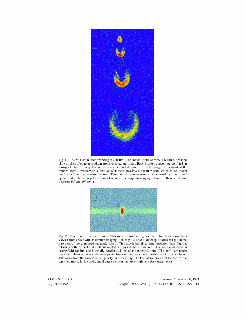
Fig. 11. The MIT atom laser operating at 200 Hz. The movie (field of view 1.8 mm x 3.9 mm)shows pulses of coherent sodium atoms coupled out from a Bose-Einstein condensate confined ina magnetic trap. Every five milliseconds, a short rf pulse rotated the magnetic moment of thetrapped atoms, transferring a fraction of these atoms into a quantum state which is no longerconfined (Ònon-magneticÓm=0 state). These atoms were accelerated downward by gravity andspread out. The atom pulses were observed by absorption imaging. Each of them containedbetween 105 and 106 atoms.
Fig. 12. Top view of the atom laser. This movie shows a singe output pulse of the atom laserviewed from above with absorption imaging. The rf pulse used to outcouple atoms can put atomsinto both of the untrapped magnetic states. This movie has finer time resolution than Fig. 11,allowing both the m=1 and m=0 outcoupled components to be observed. The m=1 component isstrong field seeking, and is rapidly accelerated out of the magnetic trap. The m=0 componenthas very little interaction with the magnetic fields of the trap, so it expands almost ballistically andfalls away from the camera under gravity, as seen in Fig. 11 (The lateral motion at the end of thetop-view movie is due to the small angle between the probe light and the vertical axis).
#3983 - $15.00 US Received November 10, 1998
(C) 1998 OSA 13 April 1998 / Vol. 2, No. 8 / OPTICS EXPRESS 310
Interference between two condensates
The spatial coherence of individual outcoupled pulses was proven in an interferenceexperiment. Long range coherence is closely related to the existence of a macroscopic phase.As with any quantum mechanical phase, one cannot measure the absolute phase of a singleatom laser pulse, but only the relative phase between two pulses. It is a non-trivial questionwhether two independent condensates have a well-defined relative phase. The analogousquestion for superfluids is this: If two superfluids are brought into a weak contact, is there arelative phase which would result in an observable dc Josephson current[33]? There is nowgeneral agreement that even if the phase is not initially defined, every realization of theexperiment will show a distinct phase[34]. This is often called spontaneous symmetrybreaking, and is a consequence of the quantum measurement process. In the case of twoindependent overlapping condensates one expects to observe a high-contrast interferencepattern, but the phase of the pattern should randomly vary between different realizations.
Two trappedBose condensates
8 mm drop(40 msec)and (anisotropic)expansion
Condensates overlapand interfere
Probe laser
Selectingatoms
Opticalpumpingbeam
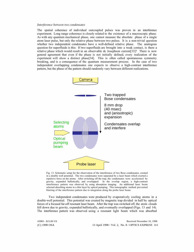
Fig. 13. Schematic setup for the observation of the interference of two Bose condensates, createdin a double well potential. The two condensates were separated by a laser beam which exerted arepulsive force on the atoms. After switching off the trap, the condensates were accelerated bygravity, expanded ballistically, and overlapped. In the overlap region, a high-contrastinterference pattern was observed by using absorption imaging. An additional laser beamselected absorbing atoms in a thin layer by optical pumping. This tomographic method preventedblurring of the interference pattern due to integration along the probe laser beam.
Two independent condensates were produced by evaporatively cooling atoms in adouble-well potential. This potential was created by magnetic trap divided in half by opticalforces of a focused far-off resonant laser beam. After the trap was switched off, the atom cloudsfell down due to gravity, expanded ballistically, and eventually overlapped (Figs. 13 and 14).The interference pattern was observed using a resonant light beam which was absorbed
#3983 - $15.00 US Received November 10, 1998
(C) 1998 OSA 13 April 1998 / Vol. 2, No. 8 / OPTICS EXPRESS 311
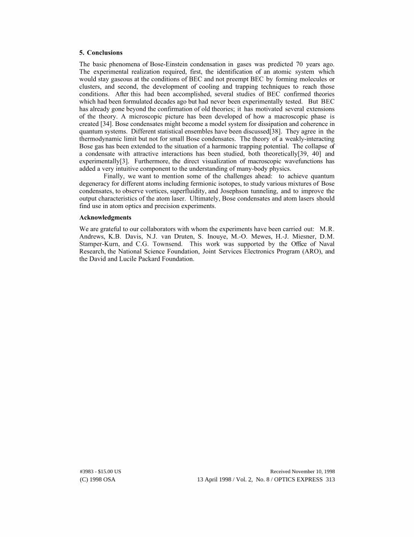
preferentially at the interference maxima[35]. As shown in Fig. 15, the interference patternconsisted of straight lines with a spacing of about 15 mm, a huge length for matter waves; thematter wavelength of atoms at room temperature is only 0.05 nm, less than the size of anatom. The interference experiment provided direct evidence for first-order coherence and long-range correlations, and for the existence of a relative phase of two condensates. Higher ordercoherences were observed in measurements of the internal energy of the condensate[36] and inmeasurements of three-body collisions[37]. All these studies were consistent with thestandard assumption that a Bose condensate is coherent to first and higher order and can becharacterized by a macroscopic wavefunction, but further studies are worthwhile and shouldlead to a more accurate characterization of the coherence properties of condensates.
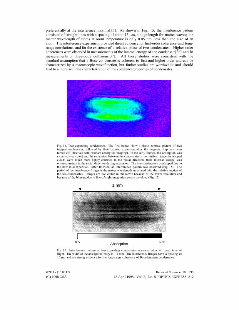
Fig. 14. Two expanding condensates. The first frames show a phase contrast picture of twotrapped condensates, followed by their ballistic expansion after the magnetic trap has beenturned off (observed with resonant absorption imaging). In the early frames, the absorption wassaturated (red color) and the separation between the condensates is not visible. Since the trappedclouds were much more tightly confined in the radial direction, their internal energy wasreleased mainly in the radial direction during expansion. The two condensates overlapped due tothe slow axial expansion. After 40 msec, an interference pattern was observed (Fig. 15). Theperiod of the interference fringes is the matter wavelength associated with the relative motion ofthe two condensates. Fringes are not visible in this movie because of the lower resolution andbecause of the blurring due to line-of-sight integration across the cloud (Fig. 13).
Absorption 50%0%
1 mm
Fig. 15. Interference pattern of two expanding condensates observed after 40 msec time offlight. The width of the absorption image is 1.1 mm. The interference fringes have a spacing of15 mm and are strong evidence for the long-range coherence of Bose-Einstein condensates.
#3983 - $15.00 US Received November 10, 1998
(C) 1998 OSA 13 April 1998 / Vol. 2, No. 8 / OPTICS EXPRESS 312
5. Conclusions
The basic phenomena of Bose-Einstein condensation in gases was predicted 70 years ago.The experimental realization required, first, the identification of an atomic system whichwould stay gaseous at the conditions of BEC and not preempt BEC by forming molecules orclusters, and second, the development of cooling and trapping techniques to reach thoseconditions. After this had been accomplished, several studies of BEC confirmed theorieswhich had been formulated decades ago but had never been experimentally tested. But BEChas already gone beyond the confirmation of old theories; it has motivated several extensionsof the theory. A microscopic picture has been developed of how a macroscopic phase iscreated [34]. Bose condensates might become a model system for dissipation and coherence inquantum systems. Different statistical ensembles have been discussed[38]. They agree in thethermodynamic limit but not for small Bose condensates. The theory of a weakly-interactingBose gas has been extended to the situation of a harmonic trapping potential. The collapse ofa condensate with attractive interactions has been studied, both theoretically[39, 40] andexperimentally[3]. Furthermore, the direct visualization of macroscopic wavefunctions hasadded a very intuitive component to the understanding of many-body physics.
Finally, we want to mention some of the challenges ahead: to achieve quantumdegeneracy for different atoms including fermionic isotopes, to study various mixtures of Bosecondensates, to observe vortices, superfluidity, and Josephson tunneling, and to improve theoutput characteristics of the atom laser. Ultimately, Bose condensates and atom lasers shouldfind use in atom optics and precision experiments.
Acknowledgments
We are grateful to our collaborators with whom the experiments have been carried out: M.R.Andrews, K.B. Davis, N.J. van Druten, S. Inouye, M.-O. Mewes, H.-J. Miesner, D.M.Stamper-Kurn, and C.G. Townsend. This work was supported by the Office of NavalResearch, the National Science Foundation, Joint Services Electronics Program (ARO), andthe David and Lucile Packard Foundation.
#3983 - $15.00 US Received November 10, 1998
(C) 1998 OSA 13 April 1998 / Vol. 2, No. 8 / OPTICS EXPRESS 313


![Bose-Einstein Condensation with High Atom Number in a Deep ... · Bose-Einstein condensation was predicted in 1925 [Bose, 1924, Einstein, 1925], at the time when quantum mechanics](https://img.pdfslide.net/doc/110x75/5f0235fc7e708231d4031fe6/bose-einstein-condensation-with-high-atom-number-in-a-deep-bose-einstein-condensation.jpg)