Embed Size (px)
Citation preview
Experimental Study and Analysis ofHarmonics Generation in Uncontrolled and
Controlled Rectifier ConvertersAslam P. Memon, Ahsan Zafar, M. Usman Keerio, Waqar Ahmad Adil, Asif Ali. A
Department of Electrical Engineering,Quaid-a-Awam University of Engineering Science & Technology, Nawabshah, Sindh, Pakistan
Abstract: Experimental studies of power converters rectifiers, their performance with different loads and their analysis isincluded in this research. These results are laboratory based in which controlled and uncontrolled rectification (FW, 1- &3- ) are observed with different loads (R, R-L) with their output rectified waveforms. Software models are developed,bases on the attained parameters in order to compare their precision with laboratory models and the final harmonics andtotal harmonic distortion produced by the power rectifier converters due to non linear loads are concluded.
Key words: Rectifier, Thyristor, Matlab, Simulation, FFT
INTRODUCTION
Rectification circuit is the primitive Power Electronics circuit which transforms AC into DC and also used in many fields.Simulation with modeling is often used to analyze the working process of the rectification. Working theory of rectification circuitand the harmonic components can be studied more deeply on the basis of analysis and conclusion of the simulation results.Analysis of the target, in this paper is done by single phase and three phase full wave uncontrolled and controlled rectificationcircuit and been modeled practically and also by MATLAB/SIMULINK. Then harmonics of AC side current and waveforms areanalyzed with these models.
Experimental & Simulink AnalysisFirst the Rectifier Models are made practically in the Power Electronics lab using the 70-002 Thyristor Control Panel of
Feedback Company. And after that same models are simulated in Matlab using the same parameters which are used inpractical trainer. Fig. 1(a) shows the 70-002 Thyristor Control Panel. By using this panel all the uncontrolled and controlledrectifiers are performed. The trainer includes the different components whose ratings are given below in table 1.
Fig. 1: 70-002 Thyristor Control Panel
Table 1: System ComponentsEquipment Ratings
1- voltage 200V ac
3- voltage Phase-to-phase 173V ac
3- voltage Phase-to-ground 100VacInductive load 700mHResistive Load 182Frequency 50 HzOscilloscope, Moving iron voltmeter/ammeter (mean values)Multimeter (rms values)
International Journal of Scientific & Engineering Research, Volume 5, Issue 1, January-2014 ISSN 2229-5518 1343
IJSER © 2014 http://www.ijser.org
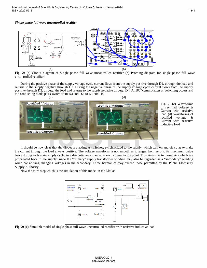
Single phase full wave uncontrolled rectifier
(a) (b)Fig. 2: (a) Circuit diagram of Single phase full wave uncontrolled rectifier (b) Patching diagram for single phase full waveuncontrolled rectifier
During the positive phase of the supply voltage cycle current flows from the supply positive through D1, through the load andreturns to the supply negative through D3. During the negative phase of the supply voltage cycle current flows from the supplypositive through D2, through the load and returns to the supply negative through D4. At 1800 commutation or switching occurs andthe conducting diode pairs switch from D3 and D2, to D1 and D4.
(c) (d)
Fig. 2: (c) Waveformsof rectified voltage &Current with resistiveload (d) Waveforms ofrectified voltage &Current with resistiveinductive load
It should be now clear that the diodes are acting as switches, synchronized to the supply, which turn on and off so as to makethe current through the load always positive. The voltage waveform is not smooth as it ranges from zero to its maximum valuetwice during each main supply cycle, in a discontinuous manner at each commutation point. This gives rise to harmonics which arepropagated back to the supply, since the “primary” supply transformer winding may also be regarded as a “secondary” windingwhen considering changing voltages in the secondary. These harmonics may exceed those permitted by the Public ElectricitySupply Authority.
Now the third step which is the simulation of this model in the Matlab.
Fig. 2: (e) Simulink model of single phase full wave uncontrolled rectifier with resistive inductive load
International Journal of Scientific & Engineering Research, Volume 5, Issue 1, January-2014 ISSN 2229-5518 1344
IJSER © 2014 http://www.ijser.org
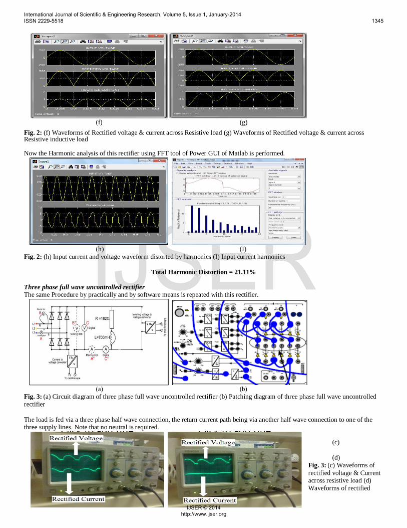
(f) (g)Fig. 2: (f) Waveforms of Rectified voltage & current across Resistive load (g) Waveforms of Rectified voltage & current acrossResistive inductive load
Now the Harmonic analysis of this rectifier using FFT tool of Power GUI of Matlab is performed.
(h) (I)Fig. 2: (h) Input current and voltage waveform distorted by harmonics (I) Input current harmonics
Total Harmonic Distortion = 21.11%
Three phase full wave uncontrolled rectifierThe same Procedure by practically and by software means is repeated with this rectifier.
(a) (b)Fig. 3: (a) Circuit diagram of three phase full wave uncontrolled rectifier (b) Patching diagram of three phase full wave uncontrolledrectifier
The load is fed via a three phase half wave connection, the return current path being via another half wave connection to one of thethree supply lines. Note that no neutral is required.
(c)
(d)Fig. 3: (c) Waveforms ofrectified voltage & Currentacross resistive load (d)Waveforms of rectified
International Journal of Scientific & Engineering Research, Volume 5, Issue 1, January-2014 ISSN 2229-5518 1345
IJSER © 2014 http://www.ijser.org
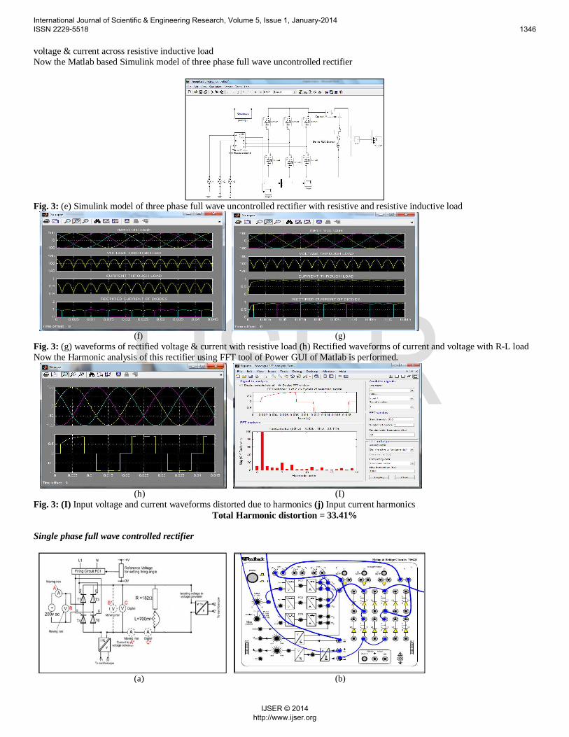
voltage & current across resistive inductive loadNow the Matlab based Simulink model of three phase full wave uncontrolled rectifier
Fig. 3: (e) Simulink model of three phase full wave uncontrolled rectifier with resistive and resistive inductive load
(f) (g)Fig. 3: (g) waveforms of rectified voltage & current with resistive load (h) Rectified waveforms of current and voltage with R-L loadNow the Harmonic analysis of this rectifier using FFT tool of Power GUI of Matlab is performed.
(h) (I)Fig. 3: (I) Input voltage and current waveforms distorted due to harmonics (j) Input current harmonics
Total Harmonic distortion = 33.41%
Single phase full wave controlled rectifier
(a) (b)
International Journal of Scientific & Engineering Research, Volume 5, Issue 1, January-2014 ISSN 2229-5518 1346
IJSER © 2014 http://www.ijser.org
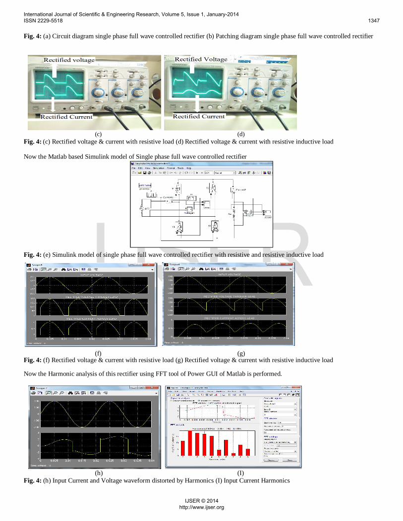
Fig. 4: (a) Circuit diagram single phase full wave controlled rectifier (b) Patching diagram single phase full wave controlled rectifier
(c) (d)Fig. 4: (c) Rectified voltage & current with resistive load (d) Rectified voltage & current with resistive inductive load
Now the Matlab based Simulink model of Single phase full wave controlled rectifier
Fig. 4: (e) Simulink model of single phase full wave controlled rectifier with resistive and resistive inductive load
(f) (g)Fig. 4: (f) Rectified voltage & current with resistive load (g) Rectified voltage & current with resistive inductive load
Now the Harmonic analysis of this rectifier using FFT tool of Power GUI of Matlab is performed.
(h) (I)Fig. 4: (h) Input Current and Voltage waveform distorted by Harmonics (I) Input Current Harmonics
International Journal of Scientific & Engineering Research, Volume 5, Issue 1, January-2014 ISSN 2229-5518 1347
IJSER © 2014 http://www.ijser.org
Total Harmonics Distortion = 37.40%
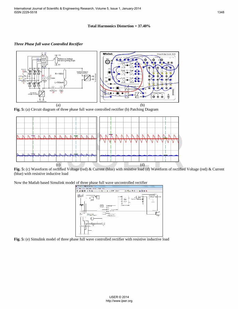
Three Phase full wave Controlled Rectifier
(a) (b)Fig. 5: (a) Circuit diagram of three phase full wave controlled rectifier (b) Patching Diagram
(c) (d)Fig. 5: (c) Waveform of rectified Voltage (red) & Current (blue) with resistive load (d) Waveform of rectified Voltage (red) & Current(blue) with resistive inductive load
Now the Matlab based Simulink model of three phase full wave uncontrolled rectifier
Fig. 5: (e) Simulink model of three phase full wave controlled rectifier with resistive inductive load
International Journal of Scientific & Engineering Research, Volume 5, Issue 1, January-2014 ISSN 2229-5518 1348
IJSER © 2014 http://www.ijser.org
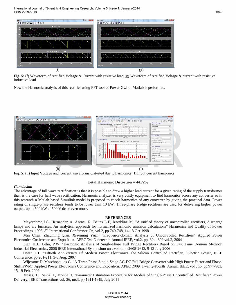
(f) (g)Fig. 5: (f) Waveform of rectified Voltage & Current with resistive load (g) Waveform of rectified Voltage & current with resistiveinductive load
Now the Harmonic analysis of this rectifier using FFT tool of Power GUI of Matlab is performed.
(h) (I)Fig. 5: (h) Input Voltage and Current waveforms distorted due to harmonics (I) Input current harmonics
Total Harmonic Distortion = 44.72%ConclusionThe advantage of full wave rectification is that it is possible to draw a higher load current for a given rating of the supply transformerthan is the case for half wave rectification. Harmonic analyzer is very costly equipment to find harmonics across any converter so inthis research a Matlab based Simulink model is proposed to check harmonics of any converter by giving the practical data. Powerrating of single-phase rectifiers tends to be lower than 10 kW. Three-phase bridge rectifiers are used for delivering higher poweroutput, up to 500 kW at 500 V dc or even more.
REFERENCESMayordomo,J.G, Hernandez A. Asensi, R. Beites L.F, Izzeddine M. "A unified theory of uncontrolled rectifiers, discharge
lamps and arc furnaces. An analytical approach for normalized harmonic emission calculations" Harmonics and Quality of PowerProceedings, 1998. 8th International Conference On, vol.2, pp.740-748, 14-18 Oct 1998
Min Chen, Zhaoming Qian, Xiaoming Yuan, "Frequency-domain Analysis of Uncontrolled Rectifiers” Applied PowerElectronics Conference and Exposition. APEC '04. Nineteenth Annual IEEE, vol.2, pp. 804- 809 vol.2, 2004
Lian, K.L, Lehn, P.W, "Harmonic Analysis of Single-Phase Full Bridge Rectifiers Based on Fast Time Domain Method"Industrial Electronics, 2006 IEEE International Symposium on , vol.4, pp.2608-2613, 9-13 July 2006
Owen E.L. "Fiftieth Anniversary Of Modern Power Electronics The Silicon Controlled Rectifier, “Electric Power, IEEEConference. pp.201-211, 3-5 Aug. 2007
Wijeratne D. Moschopoulos G. "A Three-Phase Single-Stage AC-DC Full Bridge Converter with High Power Factor and Phase-Shift PWM" Applied Power Electronics Conference and Exposition. APEC 2009. Twenty-Fourth Annual IEEE, vol., no.,pp.977-983,15-19 Feb. 2009
Mesas, J.J, Sainz, L, Molina, J, "Parameter Estimation Procedure for Models of Single-Phase Uncontrolled Rectifiers" PowerDelivery, IEEE Transactions vol. 26, no.3, pp.1911-1919, July 2011
International Journal of Scientific & Engineering Research, Volume 5, Issue 1, January-2014 ISSN 2229-5518 1349
IJSER © 2014 http://www.ijser.org

Wang Zi-qi, Jiang De-long, Fu Jin-guang, "Analysis and simulation of single-phase rectification filter circuit based onmatlab" Power Engineering and Automation Conference (PEAM), IEEE , vol.2, pp.1,3, 8-9 Sept. 2011
First A. Hemant Mehar, “MATLAB Simulation Techniques in the Power Electronics”, IEEE Technology and EngineeringEducation (ITEE), VOL.7, NO.4 December, 2012
Alexa D, Sirbu A.. Lazar,A, "Three-Phase Rectifier With Near Sinusoidal Input Currents and Capacitors Connected on the ACSide" Industrial Electronics, IEEE Transactions on, vol.53, no.5, pp.1612-1620, Oct. 2006
Zhong Chen, Yingpeng Luo, Yinyu Zhu, Guoqiao Shen, "Analysis and design of three-phase rectifier with near-sinusoidal inputcurrents," Power Electronics and Motion Control Conference. IPEMC '09. IEEE 6th International pp.1703-1-1703-7, 17-20 May 2009
International Journal of Scientific & Engineering Research, Volume 5, Issue 1, January-2014 ISSN 2229-5518 1350
IJSER © 2014 http://www.ijser.org