Embed Size (px)
Citation preview
ENGINEERING RESEARCH JOURNAL (ERJ)
Vol. 1, No. 50 October 2021, pp.67-76
Journal Homepage: erj.bu.edu.eg
- 67 -
Experimental study and thermal performance evaluation of
staggered cross flow heat exchangers of semi-circular
tubes: I- Effect of pitch ratio and space between bases
A.A.Alghrubah, M.A. Abd Elrahman, M.F. Abd Rabbo, Y.A. Al-Mashad, M.R. Salem
Mechanical Engineering Department, Faculty of Engineering at Shoubra, Benha University, Shoubra, Cairo, Egypt
Abstract : Staggered cross flow heat exchangers are commonly employed as air coolers and steam generators. This
study aims to boost their thermal performance by proposing a modification to the tube geometry; semicircular tube
(SCT) instead of complete circular tube (CCT). Through the runs, numerous gaps between SCTs-bases with different
pitches in both longitudinal/transversal directions are tested. The runs are performed with moving cooling water
through the tubes while heating air flows across the tube bundles. The results state that the SCT can be used as a passive
approach for augmenting the heat exchange rates. As geometry, increasing the gap between their bases increases both
the heat exchange rate and fluid pressure loss at the same time. Additionally, reducing the longitudinal and/or
transversal pitch ratios leads to enlarging these increases. In addition, the thermal performance index (TPI) is slightly
augmented by extending the distance between the SCTs’ bases or reducing the transversal and/or longitudinal spacings. Also, an increase in the TPI is resulted by raising the airflow rate. Moreover, the extreme determined TPI is 1.98.
Keywords: Staggered; Semi-circular; Bases’ gap; Pitches; Performance.
1. Introduction
In furthermost of industries, heat is transported via
heat exchangers as in the biochemical, electric
power, refrigeration, heat recovery industries.
Accordingly, augmenting the heat exchange above
that in the usual or standard practice can
significantly improve the thermal efficiency in such
applications as well as the economics of their
design and operation [1]. One of the main types of
heat exchange approaches is bundles of tubes in
cross flow. Their thermal attributes are very crucial
to be analyzed [2, 3]. The history presents several
woks on the hydrothermal behaviour of tube
bundles. Via the pertinent data accessible, many
investigators estimated a correlation to assess the
heat loading rate through staggered CCT banks [4-
9]. Biery [10] studied the heat exchange from a
finned staggered CCT bank. Several configurations
of the fins were applied. A growth in the
hydrothermal performance was resulted. Merker
and Hanke [11] performed laboratory tests on the
heat exchange and pressure loss of a cross flow on
staggered oval/CCT banks at different spacings.
The results assured that the oval shape reduced the
flow resistance. Kim et al. [12] dealt with plain
finned staggered CCT bank. Correlations were
established to assess the thermal performance
attributes. Torii et al. [13] practically inspected the
influence of conducting vortex generators to finned
CCT banks on the heat load. It was stated that the
extreme increases in the heating rate were 30% and
20% for staggered and in-line CCTs, respectively.
The matching reductions in the pressure loss were
55 and 15%. Moawed [14] practically and
numerically presented the hydrothermal
performance of an airflow across inline isofluxed
SCT bank. The authors considered a single SCT
instead of an CCT; not pairs. Numerous transversal
pitch ratios and attack angles of the SCTs were
studied. In another work, Ibrahiem and Elsayed
[15] extended the tests with staggered
configuration. Wang et al. [16] simulated the
turbulent flow attributes through a staggered CCT
bank. The visualization supplied a good description
for the vortex shedding. Khan et al. [17, 18]
presented analytical analyses for the heat exchange

Vol. 1, No. 50 October 2021, pp. 67-76 et al A.A.Alghrubah Engineering Research Journal (ERJ)
-- 68 --
rate from tube bundle of inline and staggered
arrangements. Furthermore, Khan et al. [19] applied
an entropy minimization method to examine the
thermodynamic losses caused by heat exchange and
pressure loss for air flow across CCT banks. Zhang
et al. [20] experimentally investigated the influence
of incorporating vortex generators in finned
isothermal CCT bundle of aligned and staggered
arrangements. The results stated that vortex
generators equipped to fin surfaces have tinyeffects
on heat transfer performance.
Odabaee and Hooman [21] presented numerical
simulations on the heat exchange from a metal
foam enveloped CCT bundle. Another practical
study was performed by Bayat et al. [22] using cam
shaped staggered CCT bundle. The authors reported
that the flow resistance was 92-93% lesser than
CCT bank.Gong et al. [23] presented simulations of
the heat load and flow contours around CCTs
integrated with fins/vortex generators. Kiatpachai et
al. [24] experimentally tested the result of
employing spiral fin at different pitches on hydrothermal response of cross flow heat
exchanger of two rows. Abdel-Rehim [25]
numerically studied the hydrothermal behaviour of
air across a staggered CCT bank. Zhang et al. [26]
numerically and practically examined the
hydrothermal attributes of an oblique airflow across
isofluxed tube bank with different impinging
angles. In their numerical analyses Bacellar et al.
[27] considered the effect of operating condition of
air flow across isothermal tube bundle of small
diameters between 0.5 to 2 mm. Lavasani and
Bayat [28] simulated the thermal and flow attributes of water based nanofluid across cam
shaped and CCT bundle. Compared to CCT, it was
reported that flow friction was reduced by 71% and
74% for in-line and staggered arrangement,
respectively, by using cam shape.
Toolthaisong and Kasayapanand [29] tested the
heat exchange from staggered flatten tube bundle in
cross flow. Several attack angles of the flatten tubes
were investigated. The results assured that the angle
of attack technique could boost the overall heat
exchange with higher pressure drop. Hu et al. [30] simulated the thermal attributes of airflow across
finned CCT bank with/without winglet vortex
generator of three different configurations. Li et al.
[31] conducted practical tests using staggered
twisted oval shape instead of CCTs as a tube
bundle. Deng et al. [32] presented simulations for
the particles flow and velocity patterns when
flowing across staggered bundle of CCTs in
moving bed. Zheng et al. [33] simulated the ash
deposition and heat exchange behaviour on
staggered CCTs bundles. From the presented
survey, numerous studies were practically/numerically accomplished aiming to
boost the hydrothermal attributes of tube banks. It
is clear most of the works concentrated on applying
fins/vortex generators. Here, it is aimed to test
another approach of passive techniques which do
not consume any direct power during life[34-40]. The existing study experimentally judges the heat
load/flow resistance associated with an airflow
crossing staggered pairs of CCTs/SCTs at different
airflow rates. During the runs, several spaces
between the tubes’ bases and numerous spaces
between the tubes in the longitudinal/transversal
orders are experienced. An outline of an SCT is
supplied in Fig. 1, in which the space between the
bases is expressed in a nondimensional index (gap
ratio; ), assessed as follows;
𝜆 =𝑆𝐵
𝑑𝑡,𝑜
(1)
Fig. 1 Geometry of pair of SCTs.
2. Practical Apparatus
The test bench carried out in the present work
includes two loops; hot and cold. The airflow loop
consists of an open circulating stream, which
includes a suction type air blower (5 hp), an air
valve control unit, an orifice plate gauge, a
transmission duct, pressure transmitters, a test
section with different tube configurations, a tunnel
inlet, a straightener, and an electric heater. The
cooling water loop consists of a closed stream, which includes a chiller unit, a pump, ball valves, a
flow meter, an inlet header, a test tube bundle, an
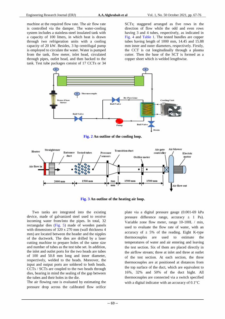
outlet header and connecting tubes. Figs. 2 and 3
show schematic diagrams of the test device. The
built-in heater consists of two stages, with a
capacity of 6 kW, and they are controlled through a
pre-set thermostat. The main tunnel is made of
galvanized steel and is shaped into a rectangle with
a width of 950 mm, a height of 250 mm and a
length of 3500 mm. The outside of the tunnel is
wrapped with glass wool. After leaving the inlet section, the air moves through the test section,
which is positioned at 2000 mm from the air entry
point. Two headers are installed in the vertical
sides.
After leaving the main channel, the air reaches
the metering channel through the transition section,
which is formed as a converging unit. The metering
channel consists of upstream PVC pipe, orifice
plate and downstream PVC pipe. The orifice plate
is designed according to the Miller standard [41].
Centrifugal type suction blower, driven by a 5 hp
electric motor, is used to supply air to the pilot
Vol. 1, No. 50 October 2021, pp. 67-76 et al A.A.Alghrubah Engineering Research Journal (ERJ)
-- 69 --
machine at the required flow rate. The air flow rate
is controlled via the damper. The water-cooling
system includes a stainless-steel insulated tank with a capacity of 100 litters, in which heat is drawn
through two refrigeration units with a cooling
capacity of 20 kW. Besides, 3 hp centrifugal pump
is employed to circulate the water. Water is pumped
from the tank, flow meter, inlet head, circulated
through pipes, outlet head, and then backed to the
tank. Test tube packages consist of 17 CCTs or 34
SCTs; staggered arranged as five rows in the
direction of flow while the odd and even rows
having 3 and 4 tubes, respectively, as indicated in Fig. 4 and Table 1. The tested bundles are copper
tubes having length of 1000 mm, 14.45 and 15.88
mm inner and outer diameters, respectively. Firstly,
the CCT is cut longitudinally through a plasma
cutter. Then the base of the SCT is formed as a
copper sheet which is welded lengthwise.
Fig. 2 An outline of the cooling loop.
Fig. 3 An outline of the heating air loop.
Two tanks are integrated into the existing
device, made of galvanized steel used to receive
incoming water from/into the pipes. In total, 32
rectangular dies (Fig. 5) made of wooden panels
with dimensions of 320 x 270 mm (wall thickness 4
mm) are located between the header and the nipples
of the ductwork. The dies are drilled by a laser cutting machine to prepare holes of the same size
and number of tubes as the test tube set. In addition,
the inlet and outlet ports for the two heads are tubes
of 100 and 50.8 mm long and inner diameter,
respectively, welded to the heads. Moreover, the
input and output ports are soldered to both heads.
CCTs / SCTs are coupled to the two heads through
dies, bearing in mind the sealing of the gap between
the tubes and their holes in the die.
The air flowing rate is evaluated by estimating the
pressure drop across the calibrated flow orifice
plate via a digital pressure gauge (0.001-69 kPa
pressure difference range, accuracy ± 1 Pa).
Variable zone flow meter, range 10-100L / min,
used to evaluate the flow rate of water, with an
accuracy of ± 5% of the reading. Eight K-type
thermocouples are used to estimate the
temperatures of water and air entering and leaving
the test section. Six of them are placed directly in
the airflow stream; three at inlet and three at outlet
of the test section. At each section, the three
thermocouples are at positioned at distances from
the top surface of the duct, which are equivalent to
16%, 32% and 50% of the duct hight. All
thermocouples are connected via a switch specified
with a digital indicator with an accuracy of 0.1C

Vol. 1, No. 50 October 2021, pp. 67-76 et al A.A.Alghrubah Engineering Research Journal (ERJ)
-- 70 --
Fig. 4 Key dimensions of tested SCTs. Fig. 5 Photo of the incorporated SCTs.
Table 1 Dimensions of the established tube banks.
3. Test Procedures
To start the tests, air blower, air gate control
unit, orifice plate, transmission channel, test
section, inlet duct, straightener, heater, tube bundle,
heads, refrigeration unit, pump, water flow meter,
thermocouple, and differential pressure transducer
are connected. Moreover, the tubes are loaded and
arranged in the duct according to the specified characteristics. The first step to collecting data from
the system is to fill the cooling tank with water
from the local water source. Then the blower,
cooling unit, electric heater and pump are turned
on. Fluid entry temperatures are regulated on both
sides by regulating the temperatures of both the
heater and the coolant tank through their respective
thermostats. The water flow rate is adjusted by
means of a flow meter and valve installation. While
the air flow rate is controlled via an airflow
retarder. A series of 112 experiments (7 airflow rates on 16 heat exchanger geometries shown in
Table 1) is performed on the tested tube bank
configurations. Through the test, it is assumed that
steady state was recorded at a maximum change of
0.5C within 25 min for each thermocouple.
Table 2: Operational conditions
4. Calculation methodologies
To get the properties of both fluids and to
calculate the heat load of the water and air sides,
firstly the mean temperature of the air at inlet and
outlet are assessed. Then, the bulk temperature of
the air and water are determined. These
temperatures are also employed to assess the heat
exchange of the water (𝑄𝑖) and of the air (𝑄𝑜). The
deviation between the two loads is determined and
compared to the average heat load. The maximum
deviation for all experiments is 5.1%. using the
average heat load and ∆𝑇𝐿.𝑀 (calculate for counter
flow), the 𝑈𝑜𝐴𝑡,𝑜 is calculated. Furthermore, the
correction factor is judged [42], and the thermal
resistances of fouling/conduction are ignored. So,
the 𝑈𝑜𝐴𝑡,𝑜 is only function in convection resistance
on both sides. It should be mentioned that 𝐴𝑡,𝑜 =17𝜋𝑑𝑡,𝑜𝑖𝐿𝑡for CCTs, and 𝐴𝑡,𝑜 = 𝑑𝑡,𝑜𝐿𝑡(17𝜋 + 34)
for SCTs. The convection coefficient of the water
is calculated by determining its Nui viaGnielinski
[43], Eq. (2), which is valid for 𝑅𝑒𝑖 ≥ 3000. The
Fanning friction factor in Eq. (3) is calculated
according to Filonenko [44], through Eq. (3).
𝑁𝑢𝑖 =
𝑓𝑖
2(𝑅𝑒𝑖 − 1000)𝑃𝑟𝑖
1 + 12.7√𝑓𝑖
2(𝑃𝑟𝑖
2 3⁄− 1)
[1 + (dt,h
Lt
)2 3⁄
] (2)
𝑓𝑖 = 0.25(1.82 𝑙𝑜𝑔 𝑅𝑒𝑖 − 1.64)−2 (3)
The hydraulic diameter for the water side is𝑑𝑡,𝑖
for CCTs, while for SCTs, it is determined as
𝜋𝑑𝑡,𝑖 (𝜋 + 2)⁄ . Now, the 𝑁𝑢𝑜 can be calculated
based on the outer surface of the tubes. For staggered arrangement, the maximum velocity

Vol. 1, No. 50 October 2021, pp. 67-76 et al A.A.Alghrubah Engineering Research Journal (ERJ)
-- 71 --
of the cross flow (uo,max) between the bundle is determined after comparing the ratio 2Sd/(ST+dt,o)[45], which is more than 1 for all runs. It is calculated based on the air velocity in the free duct (uo). The measured ∆Po is employed
to assess the 𝑓o as in Eq. (14) [9]. The followings are summary of the main used equations.
𝑄𝑖 = ��𝑖𝐶𝑝𝑖(𝑇𝑤,𝑜 − 𝑇𝑤,𝑖) (4)
𝑄𝑜 = ��𝑜𝐶𝑝𝑜(𝑇𝑎,𝑎𝑣𝑒,𝑖 − 𝑇𝑎,𝑎𝑣𝑒,𝑜) (5)
𝑈𝑜𝐴𝑡,𝑜 =𝑄𝑎𝑣𝑒
𝐹∆𝑇𝐿.𝑀 (6)
∆𝑇𝐿.𝑀 =(∆𝑇𝑖 − ∆𝑇𝑜)
ln [∆𝑇𝑖
∆𝑇𝑜]
(7)
1
𝑈𝑖𝐴𝑡,𝑜=
1
ℎ𝑜𝐴𝑡,𝑜
+1
ℎ𝑖𝐴𝑡,𝑖
(8)
ℎ𝑖 =𝑁𝑢𝑖 . 𝑘𝑖
𝑑𝑡,ℎ
(9)
𝑁𝑢𝑜 =ℎ𝑜𝑑𝑡,𝑜
𝑘𝑜
(10)
𝑢𝑜,𝑚𝑎𝑥 =𝑢𝑜𝑆𝑇
𝑆𝑇 − 𝑑𝑡,𝑜
(11)
𝑅𝑒𝑜,𝑚𝑎𝑥 =𝑢𝑜,𝑚𝑎𝑥𝑑𝑡,𝑜
𝑜
(12)
𝑆𝑡𝑜 =𝑁𝑢𝑜
𝑅𝑒𝑜,𝑚𝑎𝑥 . 𝑃𝑟𝑜
(13)
𝑓𝑜 =∆𝑃𝑜
2𝑁𝐿𝜌𝑜𝑢𝑜,𝑚𝑎𝑥2
(14)
5. Apparatus validation and data verification
The aforementioned steps and equations are
incorporated to validate the experimental outputs of
𝑁𝑢𝑜 and 𝑓o. Their values are compared with Eq.
(15) [4] and Eq. (16) [46]. These equations are
valid for 10 ≤ 𝑅𝑒𝑜,𝑚𝑎𝑥 ≤ 40000. The comparisons
are accomplished for CCT bundle presented in
Table 1. It is seen in Fig. 6 that maximum
documented differences are 7.1% and 6.1% for 𝑁𝑢𝑜
and 𝑓o, respectively.
𝑁𝑢𝑜 = 0.33 𝑅𝑒𝑜,𝑚𝑎𝑥0.6 𝑃𝑟𝑜
1/3 (15)
𝑓𝑜 = [0.25 +0.1175
[( − 1)1.08]] 𝑅𝑒𝑜,𝑚𝑎𝑥
−0.16 (16)
Fig. 6Outcomes of the comparisons; (a) 𝑵𝒖𝒐, (b) 𝒇𝒐.
6. Results and discussions
6.1 Influence the space between the bases
In this section, three ratios of the spacing’s
(0.126 ≤ ≤ 0.378) for bases of the SCT banks are
considered. Fig. 7 introduces the Nuo and𝑓o for the
examined spaces at different airflow rates at = =
2.0 and = 45 as a sample of the outputs. It is
understandable that just splitting the tubes leads to
augmenting the air-side heat transfer characteristics
in addition to increasing the airflow pressure drop.
These increases are enlarged by increasing the
bases spaces. Compared with the CCT bank, the
increases in Nuo and 𝑓o are 58.2% and 31.8%,
respectively, at = 0.126. While by widening the
SCT spacing ratio to 0.378, the corresponding
percentage increases are magnified to be 63.7% and 39.8%, respectively.
One of the key reasons is that splitting the tube
enlarges its contact area from (dt,o Lt) for CCT to
be (dt,o Lt + 2dt,o Lt) for pair of SCTs. In addition,
increasing the space formed between the bases of
semicircular tubes is accompanied with decreasing
the flow gap between the tubes in different
columns, which enlarges the flow mixing and
turbulence level around the SCTs, and consequently
breaks the boundary layers of the airflow. This
results in increasing both the heat exchange rate
and air-side flow resistance.

Vol. 1, No. 50 October 2021, pp. 67-76 et al A.A.Alghrubah Engineering Research Journal (ERJ)
-- 72 --
Fig. 7 The findings versus air-Reynolds number
at different spaces between the bases ( = = 2.0
and = 45; (a) 𝑵𝒖𝒐, (b) 𝒇𝒐.
6.2 Influence of transverse pitch ratio
In this section, experiments are accomplished
with staggered arrangement at three different
distances in the normal direction to the flow path (2
≤ ≤ 3). The direction of the base is fixed at angle
of 45. A sample of the findings is outlined in Fig.
8 for = 2.0, = 45 and = 0.252. It is obvious
that increasing the transversal pitch ratio of the
tubes, reduces both 𝑁𝑢𝑜 and 𝑓o by 26.8% and 4.7%,
respectively. The reduction in the heat transfer rates
can be backed to that increasing the transversal
pitch ratio of the tubes reduces the throttling for the
airflow and produces weaker impingement with the
later row of the tubes. Furthermore, this decreases
the breaking of the air boundary layer, which
consequently reduces the heat exchange rate
besides reducing the flow pressure drop.
Fig. 8 Sample of the findings at three transversal pitch
ratios ); (a) 𝑵𝒖𝒐, (b) 𝒇𝒐.
6.3 Influence of longitudinal pitch ratio
Other tests are run at the staggered
configuration to evaluate the influence of the pitch
ratio in the flow direction; three different distances
are considered ( = 2, 2.5, 3). Also, the flow
direction at the base is fixed at angle of 45. A
model of the results is declared in Fig. 9 for = 2.0,
= 45 and = 0.252.
It is recorded that increasing the longitudinal
pitch ratio of the tubes, from 2 to 3, reduces both
Nuo and 𝑓o by 7.8% and 4.6%, respectively. These
reductions can be due to increasing is
accompanied by fewer rate and weaker
impingement of the air molecules with the tubes.
This reduces the disturbance around the tubes.
Consequently, the mixings between air molecules
and tube wall are dampened, which reduce the heat
exchange rate besides decreasing the flow pressure
decay.
Fig. 9 Sample of the findings at three at different
longitudinal pitch ratios ( = 3, = 45 and =
0.252); (a) 𝑵𝒖𝒐, (b) 𝒇𝒐.
6.4Thermal performance Index
In this study, the TPI is accessible by means of
𝑆𝑡𝑜 and 𝑓o ratios [35, 47] assessed with engaging
SCTs and CCTs as heat transfer surfaces, as
indicated in Eq. (17). Figs. 10 and 11 reports a
sample of the average TPIs for different parameters.
𝑇𝑃𝐼 =𝑆𝑡𝑜,𝑆𝐶𝑇 𝑆𝑡𝑜,𝐶𝐶𝑇⁄
(𝑓𝑜,𝑆𝐶𝑇 𝑓𝑜,𝐶𝐶𝑇⁄ )1 3⁄ (17)

Vol. 1, No. 50 October 2021, pp. 67-76 et al A.A.Alghrubah Engineering Research Journal (ERJ)
-- 73 --
Fig. 10 The average TPI versus (a) SCTs’ bases-gap, (b)
transversal spacing ratio (==2 &=0.378).
Fig. 11 The average TPI versus (a) longitudinal spacing
ratio, (b) airflow rate (==2 &=0.378).
It is clear that the TPI is slightly augmented by
growing the gap between the SCTs’ plane bases or
reducing the transversal and/or longitudinal spacing
ratios. Also, there is a significant increase in the
TPI by speeding the airflow. Finally, the max. value
of TPI is 1.98.
7. Summary
This study supplies tests on the hydrothermal
characteristics of staggered CCT/SCT banks at a
widespread range of air flowing rates crosswise the
bundle. Through the runs, numerous gaps between
SCTs-bases with different pitches in both
longitudinal/transversal directions are tested. The
results assure that:
The SCT is an applicable passive heat transfer augmentation tool, but it increases the airflow
resistance, simultaneously, when compared
with using CCT.
The Nuoand 𝑓o are enlarged by increasing the
gap between the SCTs-bases and reducing the
longitudinal and/or transversal pitch ratios of
the tube bank.
The TPI is slightly augmented by growing the gap between the SCTs’ bases or reducing the
transversal and/or longitudinal spacing ratios.
There is an increase in the TPI by growing the
airflow rate.
The maximum informed value of TPI is 1.98.
References
[1] M.R. Salem, “Experimental investigation on
the hydrothermal attributes of MWCNT/water nanofluid in the shell-side of shell and semi-
circular tubes heat exchanger”, Applied
Thermal Engineering, vol. 176, Article no.
115438, 2020.
[2] T.L. Bergman, A.S. Lavine, F.P. Incropera and
D.P. Dewitt, “Fundamentals of Heat and Mass
Transfer”, 7th edition, John Wiley & Sons,
2011.
[3] J.W. Baughn, M.J. Elderkin, A.A. McKillop,
“Heat transfer from a single cylinder, cylinders
in tandem, and cylinders in the entrance region
of a tube bank with a uniform heat flux”, Journal of Heat Transfer, vol. 108(2), pp. 386-
391, 1986.
[4] A.P. Colburn, “A method of correlating forced
convection heat transfer data and a comparison
with fluid friction”, Transactions of the
American Institute of Chemical Engineers, vol.
29, pp. 174-210, 1933.
[5] O.L. Pierson, “Experimental investigation of
the influence of tube arrangement on
convection heat transfer and flow resistance in
cross flow of gases over tube banks”, Transactions of ASME, vol. 59, pp. 563-572,
1937.
[6] E.C. Huge, “Experimental investigation of
effects of equipment size on convection heat
transfer and flow resistance in cross flow of
gases over tube banks”, Transactions of ASME,
vol. 59, pp. 573-581, 1937.
Vol. 1, No. 50 October 2021, pp. 67-76 et al A.A.Alghrubah Engineering Research Journal (ERJ)
-- 74 --
[7] G.A. Omohundro, O.P. Bergelin, A.P. Colburn,
“Heat transfer and fluid friction during flow
across banks of tubes”, ASME Journal of Heat Transfer, vol. 71, pp. 27-34, 1949.
[8] A.J. Gram, C.O. Mackey, E.S. Monroe,
“Convection heat transfer and pressure drop of
air flowing across in-line tube banks: Part II -
Correlation of data for ten-row-deep tube
banks”, Transactions of ASME, vol. 80, pp. 25-
35, 1958.
[9] A. Zukauskas, “Heat transfer from tubes in
cross flow”, in J.P. Hartnett and T.F. Irvine, Jr.,
Eds., Advances in Heat Transfer, vol. 8,
Academic Press, New York, 1972. [10] J.C. Biery, “Prediction of heat transfer
coefficients in gas flow normal to finned and
smooth tube banks”, Journal of Heat Transfer
(ASME), vol. 103(4), pp. 705-714, 1981.
[11] G.P. Merker, H. Hanke, “Heat transfer and
pressure drop on the shell-side of tube-banks
having oval-shaped tubes”, International
Journal of Heat and Mass Transfer, vol. 29(12),
pp. 1903-1909, 1986.
[12] N.H. Kim, B. Youn, R.L. Webb, “Air-side heat
transfer and friction correlations for plain fin-
and-tube heat exchangers with staggered tube arrangements”, Journal of Heat Transfer, vol.
121(3), pp. 662-667, 1999.
[13] K. Torii, K.M. Kwak, K. Nishino, “Heat
transfer enhancement accompanying pressure-
loss reduction with winglet-type vortex
generators for fin-tube heat exchangers”,
International Journal of Heat and Mass
Transfer, vol. 45, pp. 3795-3801, 2002.
[14] M. Moawed, “Thermal performance of a cross
flow heat exchanger with semi-circular tubes”,
ERJ Shoubra Faculty of Engineering, vol. 4, pp. 87-109, June 2005.
[15] E.Z. Ibrahiem, A.O. Elsayed, “Heat transfer
performance of a semi-circular tube bank”,
Heat Transfer Research, vol. 46(6), pp. 563-
576, 2015.
[16] Y.Q. Wang, P. Jackson, T.J. Phaneuf,
“Turbulent Flow Through a Staggered Tube
Bank”, Journal of Thermophysics and Heat
Transfer, vol. 20(4), pp. 738-747, 2006.
[17] W.A. Khan, J.R. Culham, M.M. Yovanovich,
“Convection heat transfer from tube banks in crossflow: Analytical approach”, International
Journal of Heat and Mass Transfer, vol. 49 pp.
4831-4838, 2006.
[18] W.A. Khan, J.R. Culham, M.M. Yovanovich,
“Analytical model for convection heat transfer
from tube banks”, Journal of Thermophysics
and Heat Transfer, vol. 20(4), pp. 720-727,
2006.
[19] W.A. Khan, J.R. Culham, M.M. Yovanovich,
“Optimal design of tube banks in crossflow
using entropy generation minimization
method”, Journal of Thermophysics and Heat Transfer, vol. 21(2), pp. 372- 378, 2007.
[20] Y. Zhang, X. Wu, L. Wang, K. Song, Y. Dong,
S. Liu, “Comparison of heat transfer
performance of tube bank fin with mounted vortex generators to tube bank fin with punched
vortex generators”, Experimental Thermal and
Fluid Science, vol. 33, pp. 58-66, 2008.
[21] M. Odabaee, K. Hooman, “Metal foam heat
exchangers for heat transfer augmentation from
a tube bank”, Applied Thermal Engineering,
vol. 36, pp. 456-463, 2012.
[22] H. Bayat, A.M. Lavasani, T. Maarefdoost,
“Experimental study of thermal–hydraulic
performance of cam-shaped tube bundle with
staggered arrangement”, Energy Conversion and Management, vol. 85, pp. 470-476, 2014.
[23] B. Gong, L. Wang, Z. Lin, “Heat transfer
characteristics of a circular tube bank fin heat
exchanger with fins punched curve rectangular
vortex generators in the wake regions of the
tubes”, Applied Thermal Engineering, vol. 75,
pp. 224-238, 2015.
[24] P. Kiatpachai, S. Pikulkajorn, S. Wongwises,
“Air-side performance of serrated welded spiral
fin-and-tube heat exchangers”, International
Journal of Heat and Mass Transfer, vol. 89, pp.
724-732, 2015. [25] Z.S. Abdel-Rehim, “Heat transfer and turbulent
fluid flow over staggered circular tube bank”,
Energy Sources, Part A: Recovery, Utilization,
and Environmental Effects, vol. 37, pp. 164-
173, 2015.
[26] L. Zhang, Y. Ouyang, Z. Zhang, S. Wang,
“Oblique fluid flow and convective heat
transfer across a tube bank under uniform wall
heat flux boundary conditions”, International
Journal of Heat and Mass Transfer, vol. 91, pp.
1259–1272, 2015. [27] D. Bacellar, V. Aute, Z. Huang, R.
Radermacher, “Airside friction and heat
transfer characteristics for staggered tube
bundle in crossflow configuration with
diameters from 0.5 mm to 2.0 mm”,
International Journal of Heat and Mass
Transfer, vol. 98, pp. 448-454, 2016.
[28] A.M. Lavasani, H. Bayat, “Numerical study of
pressure drop and heat transfer from circular
and cam-shaped tube bank in cross-flow of
nanofluid”, Energy Conversion and Management, vol. 129, pp. 319-328, 2016.
[29] S. Toolthaisong, N. Kasayapanand, “Heat
transfer enhancement in a cross-flow heat
exchanger with modified air angles of attack”,
Journal of Energy Engineering, vol. 142(3),
article no. 04015044, pp. 1-,6 2016.
[30] W. Hu, L. Wang, Y. Guan, W. Hu, “The effect
of shape of winglet vortex generator on the
thermal–hydrodynamic performance of a
circular tube bank fin heat exchanger”, Heat
Mass Transfer, vol. 53, pp. 2961-2973, 2017.
Vol. 1, No. 50 October 2021, pp. 67-76 et al A.A.Alghrubah Engineering Research Journal (ERJ)
-- 75 --
[31] X. Li, D. Zhu, J. Sun, X. Mo, S. Liu, “Heat
transfer and pressure drop for twisted oval tube
bundles with staggered layout in crossflow of air”, Applied Thermal Engineering, vol. 148,
pp. 1092-1098, 2019.
[32] S. Deng, Z. Wen, G. Lou, D. Zhang, F. Su, X.
Liu, R. Dou, “Process of particles flow across
staggered tubes in moving bed”, Chemical
Engineering Science, vol. 217, article no.
115507, 2020.
[33] Z. Zheng, W. Yang, Y. Cai, Q. Wang, G. Zeng,
“Dynamic simulation on ash deposition and
heat transfer behavior on a staggered tube
bundle under high-temperature conditions”, Energy, vol. 190, article no. 116390, 2020.
[34] M.R. Salem, K.M. Elshazly, R.Y. Sakr, R.K.
Ali, Experimental study on convective heat
transfer and pressure drop of water-based
nanofluid inside shell and coil heat exchanger,
PhD dissertation, Faculty of Engineering at
Shoubra, Benha University, 2014.
[35] M.R. Salem, M.B. Eltoukhey, R.K. Ali, K.M.
Elshazly, “Experimental investigation on the
hydrothermal performance of a double-pipe
heat exchanger using helical tape insert”,
International Journal of Thermal Sciences, vol. 124, pp. 496-507, 2018.
[36] K.M. Elshazly, R.Y. Sakr, R.K. Ali, M.R.
Salem, “Effect of γ-Al2O3/Water Nanofluid on
the Thermal Performance of Shell and Coil
Heat Exchanger with Different Coil Torsions”,
Heat and Mass Transfer, vol. 53 (6), 1893-
1903, 2017.
[37] M.R. Salem, “Performance enhancement of a
vapor compression refrigeration system using
R134a/MWCNT-oil mixture and liquid-suction
heat exchanger equipped with twisted tape turbulator”, International Journal of
Refrigeration, vol. 120, 357-369, 2020.
[38] S.M. Elshamy, M.T. Abdelghany, M.R. Salem,
O.E. Abdellatif, “Based Al2O3 Nanofluid
Including Diverse Coil Geometries: An
Experimental Study”, Journal of Nanofluids,
vol. 9 (1), 13-23, 2020.
[39] M.R. Salem, H.A. El-Gammal, A.A. Abd-
Elaziz, K.M. Elshazly, “Study of the
performance of a vapor compression
refrigeration system using conically coiled tube-in-tube evaporator and condenser”,
International Journal of Refrigeration, vol. 99,
393-407, 2019
[40] H.A. Refaey, E. Specht, M.R. Salem,
“Influence of Fuel Distribution and Heat
Transfer on Energy Consumption in Tunnel
Kilns”, International Journal of Advances in
Engineering & Technology (IJAET), vol. 8(3),
281-293, 2015.
[41] R.W. Miller, “Flow measurement engineering
handbook”, 3rd edition, New York: McGraw-
Hill, 2000. [42] R.K. Shah, D.P. Sekulić, “Fundamentals of
heat exchanger design”, 6th edition, Hoboken,
NJ: John Wiley & Sons, p. 189, 2003.
[43] V. Gnielinski, “New equations for heat and
mass transfer in turbulent pipe and channel
flow”, International Chemical Engineering, vol. 16, pp. 359-368, 1976.
[44] G.K. Filonenko, “Hydraulic resistance of pipes
(HydraulischerWiderstand von
Rohrleitungen),” Teploenergetika, vol. 1(4), pp.
40-44, 1954.
[45] F.W. Dittus, L.M.K. Boelter, “Heat transfer in
automobile radiators of the tubular type”,
University of California Publications in
Engineering, vol. 2, p. 433, 1930.
[46] M. Jakob, “Heat transfer and flow resistance in
cross flow of gases over tube banks”, Trans. ASME, vol. 60, p. 384, 1938.
[47] H.H. Al-Kayiem, A. Bin Ekhwan, L.N. Muhi,
“Augmentation of ribs turbulators height on the
hydrothermal performance of double pipe heat
exchanger”, Journal of Engineering Science
and Technology, vol. 12(2), pp. 548-563, 2017.
Appendix A: Uncertainty Estimation
According to the manufacturer, the uncertainty in
the CCT diameters is 0.01 mm. Moreover, the
uncertainty in the spacing between the SCT-bases
and pitches is ±0.01 mm. Furthermore, the
uncertainty in the other measured dimensions is
assumed to be ±0.5 mm. Therefore, the maximum
uncertainties in the spacing ratios, distances and
areas are;
ωλ
λ= ±√(
ωSB
SB
)2
+ (−ωdt,o
dt,o
)
2
= ±0.504% (18)
ω
=
ω
= ±√(
ωST
ST
)2
+ (−ωdt,o
dt,o
)
2
= ±0.076% (19)
ωST−dt,o= ±√(ωST
)2
+ (−ωdt,o)
2== ±0.014 mm (20)
ωAt,o
At,o
= ±√(ωdt,o
dt,o
)
2
+ (ωLt
Lt
)2
= ±0.082% (21)
ωAt,i
At,i
= ±√(ωdt,i
dt,i
)
2
+ (ωLt
Lt
)2
= ±0.087% (22)
ωAbore
Abore
= ±√(ωW
W)
2
+ (ωH
H)
2
= ±0.21% (23)
ωAorifice
Aorifice
= ±√(2ωdorifice
dorifice
)2
= ±0.984% (24)
The uncertainties in the temperature readings and
temperature differences are;
ω∆Tw= ±√(ωTw,o
)2
+ (−ωTw,i)
2= ±0.71℃ (25)
ω∆Ta= ±√(
∂∆Ta
∂Ta,i
ωTa,i)
2
+ (∂∆Ta
∂Ta,o
ωTa,o)
2
= ±0.06℃ (26)
ω∆Ti= ω∆To
= ±√(∂∆Ti
∂Ta,ave,i
ωTa,ave,i)
2
+ (∂∆Ti
∂Tw,o
ωTw,o)
2
≅ ±0.5℃ (27)
ω∆TL.M= ±
ωT√2
ln [∆Ti
∆To]
√2 − 2∆TL.M (1
∆Ti
+1
∆To
) + ∆TL.M2 (
1
∆Ti2 +
1
∆To2
) (28)
The uncertainties applied to the thermal
properties of the working fluids are assumed to
be ±0.1%. The uncertainties associated with
estimating the tank volume and collecting time
are ±0.01 litre and ±1 s, respectively. The

Vol. 1, No. 50 October 2021, pp. 67-76 et al A.A.Alghrubah Engineering Research Journal (ERJ)
-- 76 --
measurement is taken for a flow rate of 50
l/min. Therefore, the uncertainty is found to be
1.67% of the full scale, as follows;
ωVw= ± √(
∂Vw
∂Vw
ωVw)
2
+ (∂Vw
∂tωt)
2
= ± √(1
tωVw
)2
+ (−V
t2ωt)
2
(29)
The uncertainty in water mass flow rate and Reynolds
number are obtained as follows;
ωmw
mw
= ±√(ωρw
ρw
)
2
+ (ωVw
Vw
)
2
= ±1.67% (30)
ωRei
Rei
= ±√(ωmw
mw
)2
+ (ωdt,h
dt,h
)
2
+ (ωμi
μi
)
2
≅ ±1.67% (31)
The maximum uncertainties in the air velocities,
Reynolds number and flow rate are calculated as
follows;
ωuo
uo
= ±√(0.7566 ωHo
Ho
)
2
+ (ωAbore
Abore
)2
+ (ωAorifice
Aorifice
)2
≅ ±4.29% (32)
ωuo,max
uo,max= ±√(
ωuo
uo)
2
+ (ωST
ST)
2
+ (ωST−dt,o
ST − dt,o
)
2
≅ ±4.29% (33)
ωReo,max
Reo,max= ±√(
ωuo,max
uo,max
)
2
+ (ωdt,o
dt,o
)
2
+ (ωo
o)
2
≅ ±4.29% (34)
ωVo
Vo
= ±0.7566 ω∆Horifice
ω∆Horifice
= ±0.32% (max. value) (35)
ωmo
mo= ±√(
ωVo
Vo
)
2
+ (ωρo
ρo
)
2
= ±0.33% (max. value) (36)
The maximum uncertainties in the heat transfer loads
and other performance parameters are evaluated as
follows; ωQo
Qo
= ±√(ωmo
mo
)2
+ (ωCpo
Cpo
)2
+ (ω∆Ta
∆Ta
)2
= ±4.04% (max. value) (37)
ωQi
Qi
= ±√(ωmi
mi
)2
+ (ωCpi
Cpi
)2
+ (ω∆Tw
∆Tw
)2
= ±1.69% (max. value) (38)
ωQave= ±
1
2√(ωQo
)2
+ (ωQi)
2= ±2.19% (max. value) (39)
ωUo
Uo
= ±√(ωQave
Qave
)2
+ (−ωAt,o
At,o
)
2
+ (−ω∆TL.M
∆TL.M
)2
= ±2.26% (max. value) (40)
ωNui
Nui
= ±√(0.8 ωRei
Rei
)
2
+ (0.4 ωPri
Pri
)
2
≅ ±1.34% (max. value) (41)
ωhi
hi
= ±√(ωNui
Nui
)
2
+ (ωki
ki
)2
+ (−ωdt,h
dt,h
)
2
≅ ±1.35% (max. value) (42)
ωho= ±√(
∂ho
∂UoωUo
)
2
+ (∂ho
∂At,oωAt,o
)
2
+ (∂ho
∂At,iωAt,i
)
2
+ (∂ho
∂hi
ωhi)
2
≅ ±4.66% (max. ) (43)
ωNuo
Nuo
= ±√(ωho
ho
)
2
+ (ωdt,o
dt,o
)
2
+ (−ωko
ko
)2
≅ ±4.67% (max. value) (44)
ωNuo
Nuo
= ±√(ωho
ho
)
2
+ (ωdt,o
dt,o
)
2
+ (−ωko
ko
)2
≅ ±4.67% (max. value) (45)
ωSto
Sto
= ±√(ωNuo
Nuo
)
2
+ (ωReo,max
Reo,max
)
2
+ (−ωPro
Pro
)2
≅ ±6.34% (max. value) (46)
ω𝑓o
𝑓o
= ± √(ω∆Po
∆Po
)2
+ (ωρo
ρo
)
2
+ (−2ω𝑢o,max
𝑢o,max
)
2
≅ ±5.8% (max. value) (47)
ωTPI
TPI= ±√(
ωSto,SCT
Sto,SCT)
2
+ (ωSto,CCT
Sto,CCT)
2
+ (
1
3ω𝑓o,SCT
𝑓o,SCT)
2
+ (
1
3ω𝑓o,CCT
𝑓o,CCT)
2
≅ ±6.71% (max. ) (48)
Nomenclatures
A Area, m2
Cp Specific heat, J kg⁄ . ℃
d Diameter, m
𝑓 Fanning friction factor
h Convection heat transfer coefficient,
W m2⁄ . ℃
k Thermal conductivity, W m⁄ . ℃
L Length, m
m Mass flow rate, kg s⁄
P Pressure, Pa
Q Heat transfer rate, W
S Gap between the bases of two adjacent SCTs,
m T Temperature, ℃ or K
u Velocity, m/s
V Volume flow rate, m3 s⁄
Dimensionless groups
𝑁𝑢 Average Nusselt number
𝑃𝑟 Prandtl number
𝑅𝑒 Reynolds number
𝑆𝑡 Stanton number
Greek letters
∆ Differential
π A mathematical constant ≅ 3.1416
λ Base gap ratio
𝜌 Density, kg m3⁄
Attack angle,
Superscripts and subscripts
ave Average
b Base
c Cross-sectional
cir Circular
h Hydraulic
i Inner or inlet or internal
LM Logarithmic Mean
m Mean
max Maximum
o Out or outer
s Surface
t Tube
Acronyms and abbreviations CCT Complete Circular Tube
SCT Semi-Circular Tube
TPI Thermal Performance Index


![Simulation and Experimental Evaluation of Linear Parabolic ... · [18] Design and experimental evaluation of a parabolic-trough concentrating photovoltaic/thermal (CPVT) system with](https://img.pdfslide.net/doc/110x75/5fc4d9e6a37a9f6f966230b8/simulation-and-experimental-evaluation-of-linear-parabolic-18-design-and-experimental.jpg)