Embed Size (px)
Citation preview
U.P.B. Sci. Bull., Series D, Vol. 82, Iss. 3, 2020 ISSN 1454-2358
EXPERIMENTAL STUDY ON STRUCTURAL PARAMETERS
OF WIRE ARC ADDITIVE MANUFACTURING ON NICKEL
BASED ALLOY USING ARGON ARC WELDING
Bandaru KIRAN1 and Rajyalakshmi G2,*
Although improvement of Additive Manufacturing is growing rapidly,
secondary sector is demanding for manufactured samples with large dimensions.
Laser Metal Deposition methods are not able to produce samples with required
dimensions. In this situation Wire-Arc Additive Manufacturing provides large
amount of deposition rates without any size constraints. Hence, WAAM is chosen as
the best additive manufacturing for producing the near-net shape mechanical
components with good mechanical properties which are used in aeronautical
industries like aircraft parts, making efficient and lighter engines. The main aim of
this paper was to successfully manufacture a rectangular bar using Wire Arc
Additive Manufacturing (WAAM) with ERNiCr-3 as filler material using Gas
tungsten Arc Welding (GTAW) through deposition on mild steel plate.
Microstructure to be examined for different deposited layers and observe the
variation whether any cracks or defects are present to check the sustainability for
fabrication of the component. To get Macrostructure images for the clear view of
different passes and layers deposited. Wear test results to be studied for the
variation of wear depth and Coefficient of friction against time. Scanning Electron
Microscopy (SEM) to be carried out to get the surface topography of the component
and identification of dendritic and inter-dendritic structures, Energy Dispersive X-
Ray Spectroscopy (EDAX) is conducted for identifying the chemical composition of
the component and X-Ray Diffraction (XRD) is conducted for identifying the
secondary phases in the grains. Hardness test is performed on different layers to
check the hardness.
Keywords: Wire Arc Additive Manufacturing; Gas tungsten Arc Welding; Mild
steel; ERNiCr-3; Wear depth; Scanning Electron Microscopy;
Dendritic and inter-dendritic structures; Energy Dispersive X-Ray
Spectroscopy; X-Ray Diffraction; Hardness test; Cold Metal Transfer.
1. Introduction
ASTM has given a statement that additive manufacturing is the process for
joining metals layer by layer to produce product from 3d data. Additive
Manufacturing is emerging as a great alternative for the conventional
manufacturing processes. WAAM technologies include plasma welding, MIG
welding and GMAW as their investment is lower. WAAM techniques are
1 Vellore Institute of Technology, India, e-mail: [email protected] 2* Vellore Institute of Technology, India, e-mail: [email protected] (corresponding
author)
168 Bandaru Kiran and Rajyalakshmi G.
classified by the feed stock type (wire or powder), heat source (laser welding,
electron beam welding) and the deposition methods. Heat source type techniques
like laser and electron beam welding are very expensive and harmful to the
human and environment. Hence, alternative deposition methods like TIG welding
is highly suitable for performing WAAM process as this is less contaminant to
the environment, low cost and complex parts can be manufactured in less time
with low wastage of material. Many industries such as aerospace, medical,
transportation, energy and consumer products are looking for more precise
manufacturing methods like additive manufacturing.
Complex shaped parts can easily be produced with additive manufacturing
and it can produce a single complex part instead of making multiple parts and
joining them. It has high rates of deposition, low cost for the equipment and
material with accurate integrity of structure. This research paper focuses on wire
feed AM of ERNiCr-3, to produce a rectangular bar with good accuracy, surface
finish and effective mechanical properties. Additive Manufacturing is more
convenient than Traditional Manufacturing as the process replaces conventional
processes like forging. Nickel based alloy ERNiCr-3 is selected as filler material
for additive manufacturing using Gas tungsten arc welding (GTAW). TIG
welding is one among the arc-wire additive manufacturing techniques which uses
non-consumable electrode and filler material.
2. Literature Review
Studies on AM shows that it can produce parts with complex geometric shapes
more conveniently compared to conventional manufacturing process. It has some
advantages over traditional manufacturing like design flexibility, reduction in
weight, consolidation of part and assemblage. Lidong Wang and Cheryl Ann
Alexander, (2016) analyzed that application of additive manufacturing is
increasing rapidly in the field of Aerospace, Manufacturing, Automotive and
Medical Industry. Nicholas et al, (2013) considered the use of GTAW in additive
manufacturing of Ti-6Al-4Y. Experiments were conducted to investigate the
influence of common welding process parameters on the geometry of the resulting
multilayer deposit.
From the results obtained, the average thickness of the wall type deposit is
primarily a function of arc current and travel speed while build-up height is
mainly related to wire feed speed, and deposition rate. Jigar R. Parasiya, (2014)
studied that GTAW can be used with or without filler material due to which it has
a wide variety of applications compared to other welding processes. Tensile
properties determined by [R.L.KLUEH, (1980)] for the ERNiCr-3 weld metal
within the temperature range of 250c – 7320c at strain rates of 3*10-4/s and 3*10-
6/s. At higher strain rate 3*10-4/s, there is no much effect on ductility and ultimate
Experimental study on structural parameters of wire arc additive […] using argon arc welding 169
tensile strength because yield strength of the smaller weldments was less than
larger weldment. And the two types of weld sizes were studied for the effect of
workpiece dilution and noticed that more amount of dilution was present in the
smaller iron welds. I. Hajiannia, (2013) studied weldability evaluation for
dissimilar welds by using ERNiCr-3, ER309L as filler materials. After completion
of welding, optical microscopy and scanning electron microscopy (SEM) was
conducted. And the results were shown that optimum qualities are provided by
filler material ERNiCr-3.
Gas Tungsten Arc welding, otherwise called tungsten inert gas welding is a
circular segment welding process that utilizes a non-consumable tungsten terminal
to create the weld. The weld region is shielded from atmospherically pollution by
a protecting gas and a filler metal is typically utilized. The gear required for the
gas tungsten circular segment welding activity incorporates a welding light using
a non-consumable cathode, a consistent current welding power supply, and a
protecting source. Gas tungsten arc welding has two kinds of polarities in power
supply like direct current straight polarity and direct current reverse polarity.
Welding different metals frequently acquaints new troubles with GTAW welding,
because most materials don't break to frame a solid bond. In any case, welds of
divergent materials have various applications in assembling. An effective filler
rod is chosen which is of same or different in composition from the base plate that
increases the mechanical properties of the welded sample.
Additive manufacturing is more convenient than traditional manufacturing as
complex shaped parts can easily be produced with low material waste. It provides
high deposition rates, low material costs and suitable to replace manufacturing
from large forging. Using this, we can make a single component instead of
making multiple components. The nickel alloys resist high pressures and
temperatures, making them well-suitable for high-performance applications.
Hence, nickel based alloy ERNiCr-3 is used in this project work.
From the literature reviewed, there is no work present on Additive Manufacturing
using ERNiCr-3. In research on elevated temperature tensile behavior of ERNiCr-
3, observed that it has high ultimate tensile strength and ductility, so it can be used
to replace with any other material for manufacturing a component.
3. Methodology
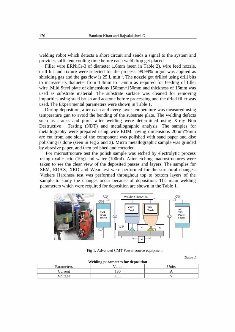
Advanced CMT (Fronius TransPuls Synergic 4000) power source and an
automatic wire feeder were used for the current work can be seen from Fig.1. The
CMT welding process is carried out based on the combination arc with negatively
and positively poled CMT cycles. CMT advanced welding process possess
significant advantages like targeted heat input, high weld deposition rate with no
increase in heat input. Cold Metal Transfer is a welding technique performed by a
170 Bandaru Kiran and Rajyalakshmi G.
welding robot which detects a short circuit and sends a signal to the system and
provides sufficient cooling time before each weld drop get placed.
Filler wire ERNiCr-3 of diameter 1.6mm (seen in Table 2), wire feed nozzle,
drill bit and fixture were selected for the process. 99.99% argon was applied as
shielding gas and the gas flow is 25 L min-1. The nozzle got drilled using drill bits
to increase its diameter from 1.4mm to 1.6mm as required for feeding of filler
wire. Mild Steel plate of dimensions 150mm*150mm and thickness of 16mm was
used as substrate material. The substrate surface was cleaned for removing
impurities using steel brush and acetone before processing and the dried filler was
used. The Experimental parameters were shown in Table 1.
During deposition, after each and every layer temperature was measured using
temperature gun to avoid the bending of the substrate plate. The welding defects
such as cracks and pores after welding were determined using X-ray Non
Destructive Testing (NDT) and metallographic analysis. The samples for
metallography were prepared using wire EDM having dimensions 20mm*9mm
are cut from one side of the component was polished with sand paper and disc
polishing is done (seen in Fig 2 and 3). Micro metallographic sample was grinded
by abrasive paper, and then polished and corroded.
For microstructure test the polish sample was etched by electrolytic process
using oxalic acid (10g) and water (100ml). After etching macrostructures were
taken to see the clear view of the deposited passes and layers. The samples for
SEM, EDAX, XRD and Wear test were performed for the structural changes.
Vickers Hardness test was performed throughout top to bottom layers of the
sample to study the changes occur because of deposition. The main welding
parameters which were required for deposition are shown in the Table 1.
Fig 1. Advanced CMT Power source equipment
Table 1
Welding parameters for deposition
Parameters Value Units
Current 130 A
Voltage 11.1 V
Welding Direction
CMT
Torch
TIG
Torch CMT
Power
Source
AC
TIG
Power
Source
W.P
d
h1 h2
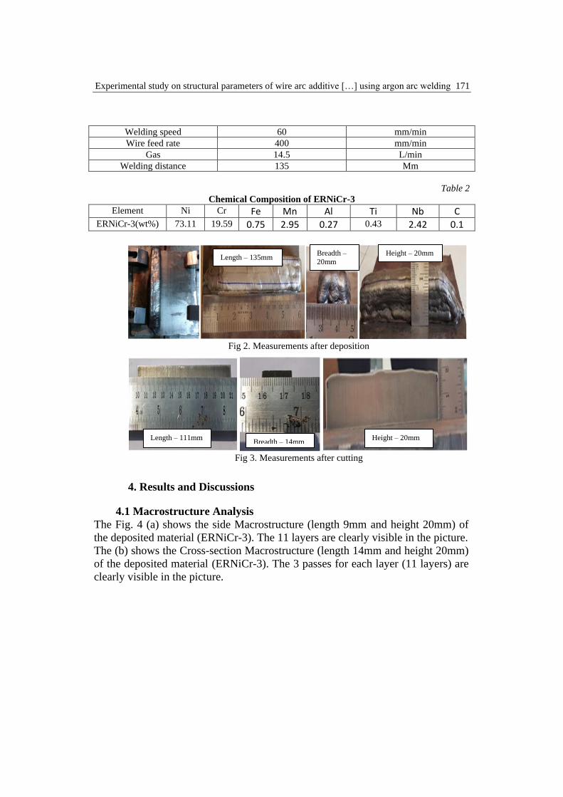
Experimental study on structural parameters of wire arc additive […] using argon arc welding 171
Welding speed 60 mm/min
Wire feed rate 400 mm/min
Gas 14.5 L/min
Welding distance 135 Mm
Table 2
Chemical Composition of ERNiCr-3
Element Ni Cr Fe Mn Al Ti Nb C ERNiCr-3(wt%) 73.11 19.59 0.75 2.95 0.27 0.43 2.42 0.1
Fig 2. Measurements after deposition
Fig 3. Measurements after cutting
4. Results and Discussions
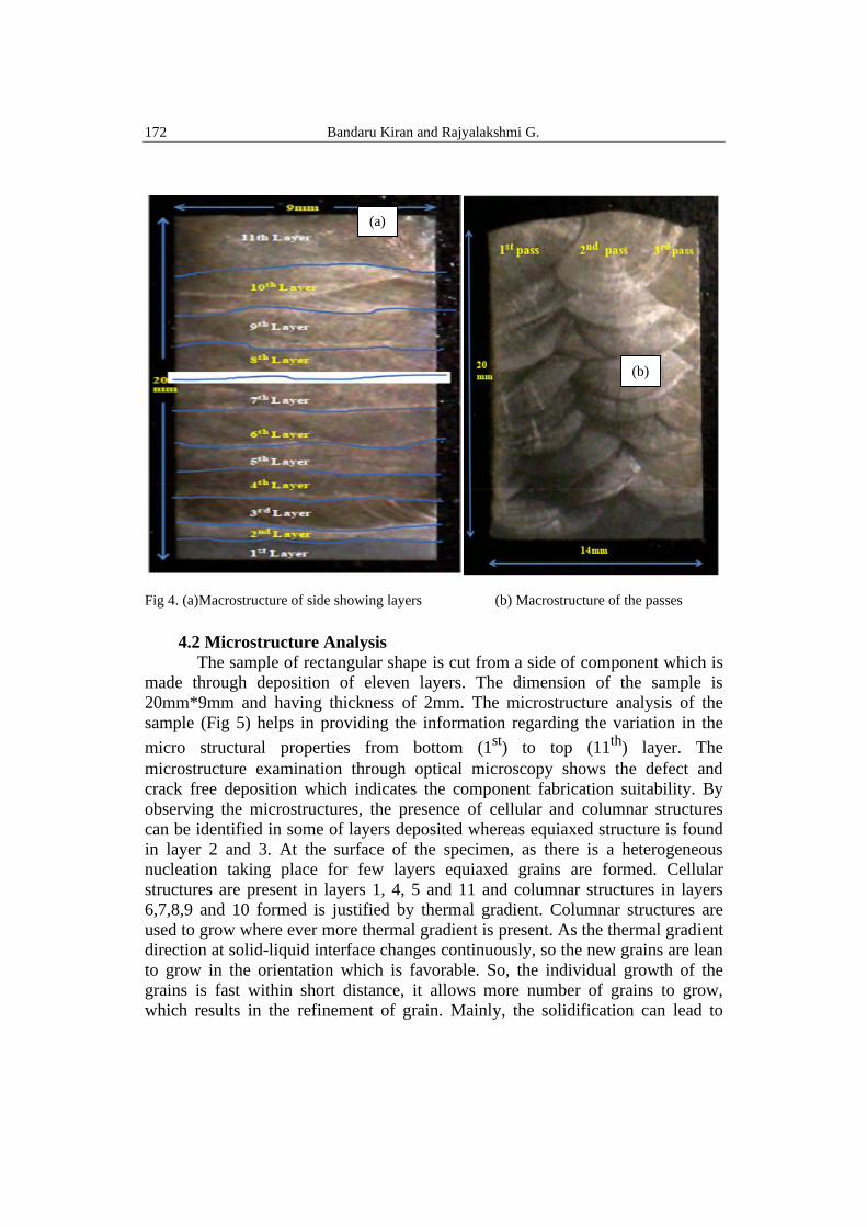
4.1 Macrostructure Analysis
The Fig. 4 (a) shows the side Macrostructure (length 9mm and height 20mm) of
the deposited material (ERNiCr-3). The 11 layers are clearly visible in the picture.
The (b) shows the Cross-section Macrostructure (length 14mm and height 20mm)
of the deposited material (ERNiCr-3). The 3 passes for each layer (11 layers) are
clearly visible in the picture.
Length – 111mm Breadth – 14mm
111mm
Height – 20mm
Length – 135mm Breadth –
20mm
Height – 20mm
172 Bandaru Kiran and Rajyalakshmi G.
Fig 4. (a)Macrostructure of side showing layers (b) Macrostructure of the passes
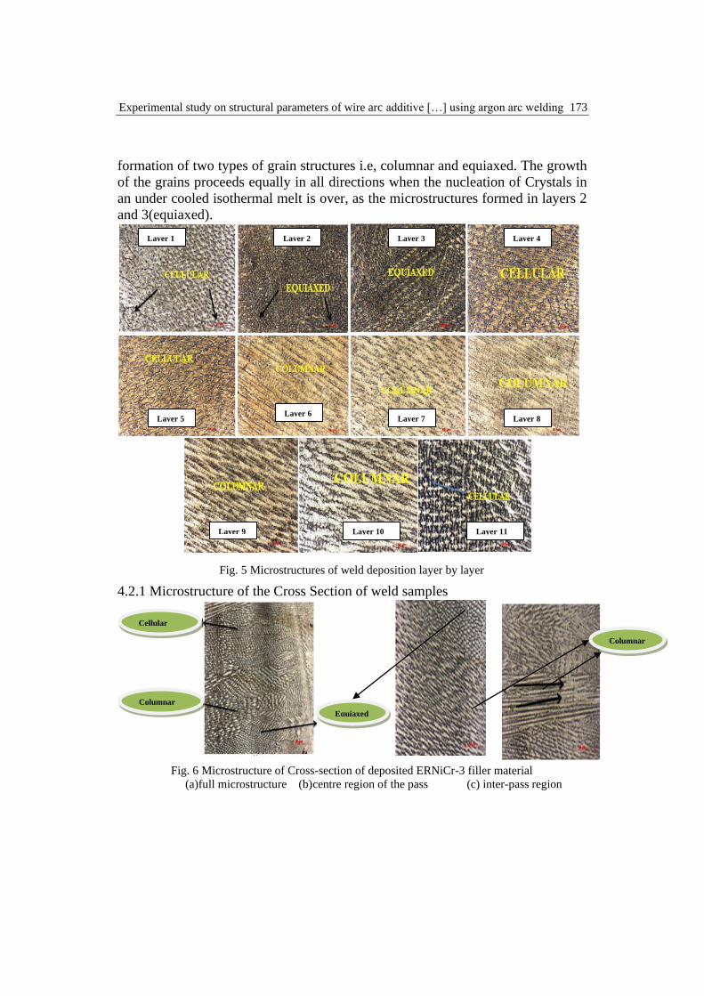
4.2 Microstructure Analysis
The sample of rectangular shape is cut from a side of component which is
made through deposition of eleven layers. The dimension of the sample is
20mm*9mm and having thickness of 2mm. The microstructure analysis of the
sample (Fig 5) helps in providing the information regarding the variation in the
micro structural properties from bottom (1st
) to top (11th
) layer. The
microstructure examination through optical microscopy shows the defect and
crack free deposition which indicates the component fabrication suitability. By
observing the microstructures, the presence of cellular and columnar structures
can be identified in some of layers deposited whereas equiaxed structure is found
in layer 2 and 3. At the surface of the specimen, as there is a heterogeneous
nucleation taking place for few layers equiaxed grains are formed. Cellular
structures are present in layers 1, 4, 5 and 11 and columnar structures in layers
6,7,8,9 and 10 formed is justified by thermal gradient. Columnar structures are
used to grow where ever more thermal gradient is present. As the thermal gradient
direction at solid-liquid interface changes continuously, so the new grains are lean
to grow in the orientation which is favorable. So, the individual growth of the
grains is fast within short distance, it allows more number of grains to grow,
which results in the refinement of grain. Mainly, the solidification can lead to
(a)
(b)
Experimental study on structural parameters of wire arc additive […] using argon arc welding 173
formation of two types of grain structures i.e, columnar and equiaxed. The growth
of the grains proceeds equally in all directions when the nucleation of Crystals in
an under cooled isothermal melt is over, as the microstructures formed in layers 2
and 3(equiaxed).
Fig. 5 Microstructures of weld deposition layer by layer
4.2.1 Microstructure of the Cross Section of weld samples
Fig. 6 Microstructure of Cross-section of deposited ERNiCr-3 filler material
(a)full microstructure (b)centre region of the pass (c) inter-pass region
Cellular
Columnar
Equiaxed
Columnar
Layer 1 Layer 2 Layer 3 Layer 4
Layer 5 Layer 6
Layer 7 Layer 8
Layer 9 Layer 10 Layer 11
174 Bandaru Kiran and Rajyalakshmi G.
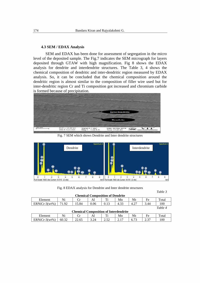
4.3 SEM / EDAX Analysis
SEM and EDAX has been done for assessment of segregation in the micro
level of the deposited sample. The Fig.7 indicates the SEM micrograph for layers
deposited through GTAW with high magnification. Fig 8 shows the EDAX
analysis for dendrite and interdendrite structures. The Table 3, 4 shows the
chemical composition of dendritic and inter-dendritic region measured by EDAX
analysis. So, it can be concluded that the chemical composition around the
dendritic region is almost similar to the composition of filler wire used but for
inter-dendritic region Cr and Ti composition got increased and chromium carbide
is formed because of precipitation.
Fig. 7 SEM which shows Dendrite and Inter dendrite structures
Fig. 8 EDAX analysis for Dendrite and Inter dendrite structures
Table 3
Chemical Composition of Dendrite
Element Ni Cr Al Ti Mn Nb Fe Total
ERNiCr-3(wt%) 71.92 15.84 0.06 0.13 4.33 4.27 3.44 100
Table 4
Chemical Composition of Interdendrite
Element Ni Cr Al Ti Mn Nb Fe Total
ERNiCr-3(wt%) 60.32 22.65 3.24 2.52 2.17 6.73 2.37 100
Dendrite Interdendrite
Experimental study on structural parameters of wire arc additive […] using argon arc welding 175
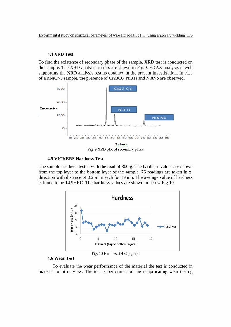
4.4 XRD Test
To find the existence of secondary phase of the sample, XRD test is conducted on
the sample. The XRD analysis results are shown in Fig.9. EDAX analysis is well
supporting the XRD analysis results obtained in the present investigation. In case
of ERNiCr-3 sample, the presence of Cr23C6, Ni3Ti and Ni8Nb are observed.
Fig. 9 XRD plot of secondary phase
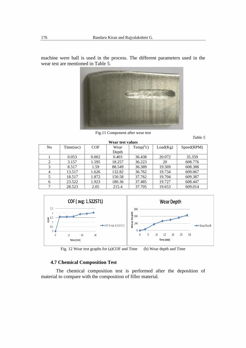
4.5 VICKERS Hardness Test
The sample has been tested with the load of 300 g. The hardness values are shown
from the top layer to the bottom layer of the sample. 76 readings are taken in x-
direction with distance of 0.25mm each for 19mm. The average value of hardness
is found to be 14.9HRC. The hardness values are shown in below Fig.10.
Fig. 10 Hardness (HRC) graph
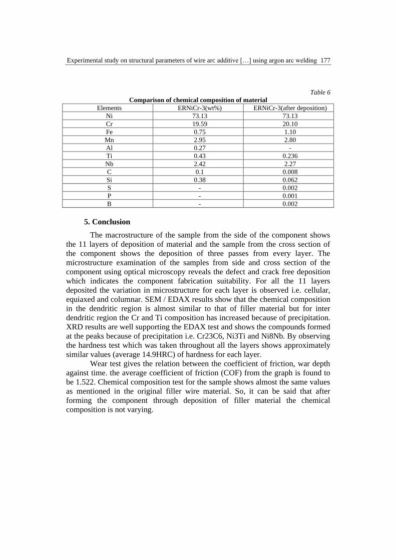
4.6 Wear Test
To evaluate the wear performance of the material the test is conducted in
material point of view. The test is performed on the reciprocating wear testing
176 Bandaru Kiran and Rajyalakshmi G.
machine were ball is used in the process. The different parameters used in the
wear test are mentioned in Table 5.
Fig.11 Component after wear test
Table 5
Wear test values
No Time(sec) COF Wear
Depth
Temp(0c) Load(Kg) Speed(RPM)
1 0.053 0.002 0.403 36.438 20.072 35.359
2 3.157 1.595 18.257 36.223 20 608.776
3 8.517 1.59 88.549 36.389 19.569 608.388
4 13.517 1.626 132.82 36.762 19.734 609.067
5 18.517 1.872 150.58 37.762 19.704 609.387
6 23.522 1.923 180.36 37.485 19.727 608.447
7 28.523 2.05 215.4 37.705 19.653 609.014
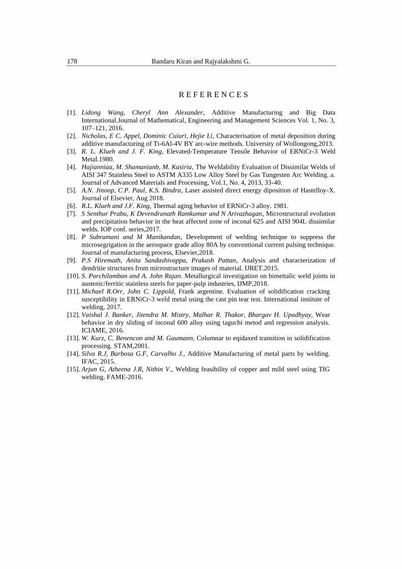
Fig. 12 Wear test graphs for (a)COF and Time (b) Wear depth and Time
4.7 Chemical Composition Test
The chemical composition test is performed after the deposition of
material to compare with the composition of filler material.
Experimental study on structural parameters of wire arc additive […] using argon arc welding 177
Table 6
Comparison of chemical composition of material
Elements ERNiCr-3(wt%) ERNiCr-3(after deposition)
Ni 73.13 73.13
Cr 19.59 20.10
Fe 0.75 1.10
Mn 2.95 2.80
Al 0.27 -
Ti 0.43 0.236
Nb 2.42 2.27
C 0.1 0.008
Si 0.38 0.062
S - 0.002
P - 0.001
B - 0.002
5. Conclusion
The macrostructure of the sample from the side of the component shows
the 11 layers of deposition of material and the sample from the cross section of
the component shows the deposition of three passes from every layer. The
microstructure examination of the samples from side and cross section of the
component using optical microscopy reveals the defect and crack free deposition
which indicates the component fabrication suitability. For all the 11 layers
deposited the variation in microstructure for each layer is observed i.e. cellular,
equiaxed and columnar. SEM / EDAX results show that the chemical composition
in the dendritic region is almost similar to that of filler material but for inter
dendritic region the Cr and Ti composition has increased because of precipitation.
XRD results are well supporting the EDAX test and shows the compounds formed
at the peaks because of precipitation i.e. Cr23C6, Ni3Ti and Ni8Nb. By observing
the hardness test which was taken throughout all the layers shows approximately
similar values (average 14.9HRC) of hardness for each layer.
Wear test gives the relation between the coefficient of friction, war depth
against time. the average coefficient of friction (COF) from the graph is found to
be 1.522. Chemical composition test for the sample shows almost the same values
as mentioned in the original filler wire material. So, it can be said that after
forming the component through deposition of filler material the chemical
composition is not varying.
178 Bandaru Kiran and Rajyalakshmi G.
R E F E R E N C E S
[1]. Lidong Wang, Cheryl Ann Alexander, Additive Manufacturing and Big Data
International.Journal of Mathematical, Engineering and Management Sciences Vol. 1, No. 3,
107–121, 2016.
[2]. Nicholas, E C. Appel, Dominic Cuiuri, Hejie Li, Characterisation of metal deposition during
additive manufacturing of Ti-6Al-4V BY arc-wire methods. University of Wollongong,2013.
[3]. R. L. Klueh and J. F. King, Elevated-Temperature Tensile Behavior of ERNiCr-3 Weld
Metal.1980.
[4]. Hajianniaa, M. Shamanianb, M. Kasiria, The Weldability Evaluation of Dissimilar Welds of
AISI 347 Stainless Steel to ASTM A335 Low Alloy Steel by Gas Tungesten Arc Welding. a.
Journal of Advanced Materials and Processing, Vol.1, No. 4, 2013, 33-40.
[5]. A.N. Jinoop, C.P. Paul, K.S. Bindra, Laser assisted direct energy diposition of Hastelloy-X.
Journal of Elsevier, Aug 2018.
[6]. R.L. Klueh and J.F. King, Thermal aging behavior of ERNiCr-3 alloy. 1981.
[7]. S Senthur Prabu, K Devendranath Ramkumar and N Arivazhagan, Microstructural evolution
and precipitation behavior in the heat affected zone of inconal 625 and AISI 904L dissimilar
welds. IOP conf. series,2017.
[8]. P Subramani and M Manikandan, Development of welding technique to suppress the
microsegrigation in the aerospace grade alloy 80A by conventional current pulsing technique.
Journal of manufacturing process, Elsevier,2018.
[9]. P.S Hiremath, Anita Sandashivappa, Prakash Pattan, Analysis and characterization of
dendritie structures from microstructure images of material. IJRET.2015.
[10]. S. Porchilamban and A. John Rajan. Metallurgical investigation on bimettalic weld joints in
austenic/ferritic stainless steels for paper-pulp industries, IJMP,2018.
[11]. Michael R.Orr, John C. Lippold, Frank argentine. Evaluation of solidification cracking
susceptibility in ERNiCr-3 weld metal using the cast pin tear test. International institute of
welding, 2017.
[12]. Vaishal J. Banker, Jitendra M. Mistry, Malhar R. Thakor, Bhargav H. Upadhyay, Wear
behavior in dry sliding of inconal 600 alloy using taguchi metod and regression analysis.
ICIAME, 2016.
[13]. W. Kurz, C. Benencon and M. Gaumann, Columnar to eqidaxed transition in solidification
processing. STAM,2001.
[14]. Silva R.J, Barbosa G.F, Carvalho J., Additive Manufacturing of metal parts by welding.
IFAC, 2015.
[15]. Arjun G, Atheena J.R, Nithin V., Welding feasibility of copper and mild steel using TIG
welding. FAME-2016.