Embed Size (px)
Citation preview
54
21. ročník - č. 4/2012
1 INTRODUCTION
Segmental tunnel lining is usually applied to mechanisedtunnelling using full-face tunnelling shields (the TBM tech-nology). Pre-cast steel fibre reinforced segments are current-ly used in praxis, containing no traditional rod reinforcement(Hilar, Beňo, 2012). In the Czech Republic, there isa research underway focused on problems of steel fibre rein-forced segments so that this technology can be applied evento Czech tunnels. A variety of samples were produced andtested in the initial phases of the research, serving for thecomparison and selection of suitable composition of steelfibre reinforced concrete mixture (Vodička et al., 2012). Theinfluence of different dosing of steel fibres on the resultantbehaviour of steel fibre reinforced concrete was subjected tocomparison. The properties of steel fibres were laboratorytested and assessed (unconfined compressive strength testedon cubes, flexural strength tested on beams). Some parame-ters of steel fibre reinforced concrete were derived backwardby means of advanced numerical modelling using the FiniteElement Method in the ANTENA simulator (Sajdlová, Pukl,2011). Traditionally reinforced concrete segments and SFRCsegments were tested by the Klokner’s Institute of the CzechTechnical University in Prague (Vokáč, Bouška, 2011). Theresults of the completed tests are presented in the paperbelow.
2 TYPES OF TESTS
Apart from the testing of small samples, first of all beams,the testing of which has been commonly conducted fora number of years, a comprehensive set of tests on real ele-ments with real sizes was carried out at present. Althoughsegments of tunnel linings are exposed to effects of a rangeof loading cases (e.g. handling, storing, transport, installati-on, final loading), measures are being introduced in praxisdesigned to make only some of them deciding for the dimen-sioning of the pre-cast elements. Naturally, the load inducedby rock mass is the principal design load. With respect to thewaterproofing capacity of a segmental lining, even the hyd-rostatic pressure can play important role, first of all when thewater table is above the tunnel level. The above-mentionedloading cases are in action throughout the design life of thestructure. Another significant loading factor is the thrust ofa tunnelling shield, which is pressed into rock mass bymeans of hydraulic rams pushing against assembled liningrings. It is true that this is a temporary construction conditi-on and short-term loading, which should not be significantas far as the as economic as possible design is concerned.
1 ÚVOD
Pro mechanizovanou ražbu pomocí plnoprofilových tunelo-vacích štítů (technologie TBM) je zpravidla aplikováno seg-mentové tunelové ostění z prefabrikovaného železobetonu.V současné době jsou v praxi stále častěji využívány segmen-ty z prefabrikovaného drátkobetonu bez tradiční prutovévýztuže (Hilar, Beňo, 2012). V České republice nyní probíhávýzkum zaměřený na problematiku drátkobetonových seg-mentů, aby danou technologii bylo možné využít i na českýchtunelech. V úvodních fázích výzkumu byla vyrobenaa odzkoušena řada vzorků pro porovnání a výběr vhodnéhosložení drátkobetonové směsi (Vodička a kol., 2012). Bylporovnáván vliv různého dávkování drátků i různých typůdrátků na výsledné chování drátkobetonu. Vlastnosti vzorkůbyly laboratorně zkoušeny a vyhodnoceny (pevnost v prostémtlaku zkoušená na krychlích, ohybová pevnost zkoušená natrámcích). Některé parametry drátkobetonu byly zpětně odvo-zovány pomocí pokročilého numerického modelování meto-dou konečných prvků v programu ATENA (Sajdlová, Pukl,2011). V Kloknerově ústavu ČVUT v Praze byly zkoušenyželezobetonové a drátkobetonové segmenty (Vokáč, Bouška,2011). Výsledky provedených zkoušek jsou prezentoványv následujícím článku.
2 TYPY ZKOUŠEK
Kromě testování malých vzorků zejména trámců, jejichž tes-tování se běžně realizuje již řadu let, byl nyní uskutečněn kom-plexní soubor testů na reálných prvcích skutečné velikosti.Přestože jsou segmenty tunelového ostění vystaveny účinkůmřady zatěžovacích stavů (např. manipulace, skladování, dopra-va, instalace, definitivní zatížení, atd.), jsou v praxi zaváděnaopatření, aby rozhodující pro dimenzování prefabrikátů bylyjen některé z nich. Zásadním návrhovým zatížením je přiroze-ně zatížení horninovým masivem. Vzhledem k vodo ne -propustnosti segmentového ostění může hrát významnou rolitaké hydrostatický tlak, zejména pokud je hladina podzemnívody nad úrovní tunelu. Uvedená zatížení působí po celoudobu životnosti konstrukce. Dalším významným zatěžovacímfaktorem je přítlak tunelovacího štítu, který je zatlačován dohorninového masivu pomocí hydraulických lisů zapřenýcho smontované prstence ostění. Jedná se sice o dočasný staveb-ní stav a krátkodobé zatížení, které by z hlediska co nejúspor-nějšího návrhu nemělo být podstatné. Avšak s ohledemna mnohdy předpokládané vysoké hodnoty přítlačné síly stro-je (závisejí na predikovaných geotechnických vlastnos-tech horninovém masivu) hraje daný zatěžovací stav často roz-hodující roli při návrhu segmentů. I vzhledem k tomuto faktu
EXPERIMENTÁLNÍ ZATĚŽOVACÍ ZKOUŠKY DRÁTKOBETONOVÝCH A ŽELEZOBETONOVÝCH PREFABRIKOVANÝCH SEGMENTŮ
PRO OSTĚNÍ TUNELŮEXPERIMENTAL LOADING TESTS OF STEEL FIBRE REINFORCED AND TRADITIONALLY REINFORCED
PRE-CAST CONCRETE SEGMENTS FOR TUNNEL LININGS
MATOUŠ HILAR, PETR VÍTEK

55
21. ročník - č. 4/2012
je třeba posuzovat technologii TBM jako celek, potřebná vyššíúnosnost ostění je kompenzována řadou výhod.
Pro simulaci rozhodujících návrhových stavů byly navrženy3 typy zkoušek (obr. 1):
A) Simulace zatížení horninovým masivem:Segment je zatěžován ohybem, a to v rovině kolmé na plo-
chu segmentu. Segment se ukládá ve tvaru klenby (obrácené"U") na posuvné podpory a zatěžuje se ve vrcholu klenbypřímkovým zatížením. Posuvné podpory znamenají namáháníprostým ohybem bez vlivu normálové síly (obr. 1a). Ačkoli veskutečnosti jsou tunelová ostění namáhána normálovou silou,pro účel zkoušení byl zvolen staticky jednodušší model, abyvýsledky byly snáze interpretovatelné a poskytly vhodnějšípodklady pro numerickou analýzu. Kombinaci s normálovýmzatížením ostění lze následně relativně snadno modelovatv numerickém výpočtu.
B) Simulace zatížení axiálními lisy štítu – ideální stav:Jak již bylo zmíněno, zatížení lisy štítu zajišťujícími potřeb-
ný přítlak stroje na čelbě je pro návrh segmentů jedenz rozhodujících zatěžovacích stavů. Je zapotřebí mít jasnou
However, with respect to the anticipated high values of thethrust force of the machine (depending on the predicted geo-technical properties of rock mass), the particular loadingcase often plays the deciding role in designing segments. Itis also with respect to this fact that the full-face TBM tech-nology must be assessed as a whole; the required higher loa-ding capacity is compensated for by numerous advantages.
The following tree types of tests were proposed for thesimulation of deciding design conditions (see Fig. 1):
A) Simulation of the rock mass induced loading:A segment is loaded by bending in a plane perpendicular
to the segment surface. The segment is placed in the positi-on of a vault (inverted ‘U’) on movable supports; a linearload acts on the top of the vault. The movable supports meanthat only a pure bending load acts, without the influence ofa normal force (see Fig. 1a). Despite the fact that tunnellinings are in reality loaded by normal forces, a staticallysimpler model was chosen for the purpose of the testing, sothat the results were easier to interpret and provided moresuitable grounds for a numerical analysis. A combinationcontaining the normal loading acting on the lining can besubsequently relatively easily modelled in a numerical cal-culation.
B) Simulation of loading induced by axial rams on theshield – an ideal condition:
As mentioned above, the loading induced by rams on theshield providing the required thrust of the machine againstthe excavation face is one of the loading cases deciding forthe segment design. It is necessary to have clear informationabout the load under which cracks start to develop and themoment at which they start to propagate throughout thelining thickness. Despite the fact that the loading capacity ofa segment can be sufficient, a crack running throughout thesegment thickness means that the lining is permeable forwater, which naturally is unacceptable. The test is arrangedin a way where the segment is loaded by a pressure insidethe central plane. With respect to the capability of the loa-ding equipment (maximum force of 10 MN – 1000 t), the testwas composed in two variants, namely with the loading bya single load (see Fig. 1b) with the possibility of reaching thetotal load-bearing capacity of the element, and the loadingby two loads (see Fig. 1c) without the possibility of reachingthe loading capacity of the element.
C) Simulation of loading induced by axial rams on theshield – non-uniform bearing of the segment:
Segments in lining rings are bonded in a way similar tobrickwork. This system brings many advantages, includingthe increase in the rigidity of the lining. When the loading bythe tunnelling shield is being applied, the loading force istransmitted to two segments of the previous ring. If the stateoccurs where the segmental lining is not assembled geome-trically accurately, the segment being loaded by rams is sup-ported non-uniformly. In the case being assessed, one seg-ment is exposed to loading in 3 points (the simulation of 3rams) and is placed on 3 supports. With respect to the factthat a statically indeterminate structure is in substance inquestion, the element is loaded by bending when a supportdrops. The test is adjusted to this fact. The segment is fixedon two supports and the side support is omitted; it is loadedby a single load acting in the central plane in the end pointof application (see Fig. 1d). The element is therefore loadedas a high cantilever.
Obr. 1 Prováděné zkoušky – a) ohyb segmentu kolmo na rovinu segmentu, b)ohyb segmentu v rovině segmentu, c) prostý tlak na segment dvěma břemeny,d) prostý tlak jedním břemenem na zbytky segmentůFig. 1 Conducted tests – a) segment bending perpendicularly to the segmentplane, b)segment bending in the segment plane, c) unilateral pressure on thesegment induced by two loads, d) unilateral pressure induced by a single loadacting on remains of segments

56
21. ročník - č. 4/2012
informaci o tom, při jakém zatížení vznikají trhliny a kdy sepropagují na plnou tloušťku ostění. Přestože segment může býtdostatečně únosný, trhlina procházející celou tloušťkou seg-mentu znamená vodopropustnost ostění, což přirozeně nenípřijatelné. Zkouška je uspořádána tak, že segment je zatěžovántlakem ve střednicové ploše. S ohledem na možnosti zatěžova-cího zařízení (maximální síla 10 MN – 1000 t) byla zkouškakoncipována ve dvou variantách, a to zatížení jedním břeme-nem (obr. 1b) s možností dosažení celkové únosnosti prvkua zatížení dvěma břemeny (obr. 1c) bez možnosti dosaženíúnosnosti prvku.
C) Simulace zatížení axiálními lisy štítu – nerovnoměrnéuložení segmentu:
Segmenty v prstencích ostění jsou provázány vazbou podob-ně jako cihelné zdivo, což přináší řadu výhod včetně zvýšenítuhosti ostění. Při zatížení tunelovacím štítem je zatěžovacísíla přenášena do dvou segmentů předcházejícího prstence.Pokud dojde k tomu, že segmentové ostění není smontovánogeometricky přesně, tak je segment zatěžovaný lisy podepřennerovnoměrně. V posuzovaném případě je jeden segmentvystaven 3 působištím zatížení (simulace 3 lisů) a uložen na 3podporách. S ohledem na fakt, že se v podstatě jedná o statickyneurčitou konstrukci, při poklesu podpory je prvek namáhánohybem. Tomu je přizpůsobena i zkouška, kdy je segment zafi-xován na dvou podporách, krajní je vynechána, a zatížen jed-ním břemenem působícím ve střednicové rovině v krajnímpůsobišti (obr. 1d). Prvek je tedy zatížen jako vysoká konzola.
3 ZKOUŠENÉ SEGMENTY
Pro výrobu prefabrikovaných segmentů určených pro zatě-žovací zkoušky byly využity formy používané k výrobě seg-mentů pro mechanizovanou ražbu traťových tunelů prodlouže-ní trasy A pražského metra. Geometrie segmentů je patrnáz obr. 2. Prstenec ostění má vnitřní průměr 5,3 m, vnější prů-měr 5,8 m, mocnost ostění (segmentů) je 0,25 m, délka jedno-ho prstence (šířka segmentů) je 1,5 m. Všechny prstence majíshodný tvar. Svislé průměty osazených prstenců mají tvarlichoběžníků, přičemž natočením vzájemným prstenců kolemjejich osy lze zajistit vedení v přímém směru i změnu směrutunelu (směrové a výškové oblouky). Tři největší segmenty(A1, A2 a A3) mají rovnoběžné ložné hrany, dva další seg-menty obdobné velikosti (B a C) jsou na straně klenáku zko-sené, závěrečný uzavírací segment (K – klenák) je zkosený nadvou ložných stranách a má přibližně třetinovou velikost.Segmenty jsou vzájemně spojovány šrouby (v podélnémi příčném směru), proto má každý segment otvory a kapsy proumístění šroubů. Vodotěsnost ostění je zajišťována pomocípryžových pásků, které jsou osazeny do obvodových drážekkaždého segmentu. Prostor mezi rubem prstence a lícem výru-bu se při dalším záběru souběžně začerpává výplňovou maltou.
Během výstavby je každý prstenec ostění zatížen pomocí 16dvojic hydraulických lisů umístěných v zadní části tunelovací-ho štítu. Lisy jsou po obvodu prstence rozmístěny rovnoměrně(úhel rotace 22,5°). Na pět velkých segmentů působí vždy 3dvojice lisů, na klenák působí pouze jedna dvojice lisů. Proúčely zkoušek byly vyrobeny dva prstence segmentůz drátkobetonu bez prutové výztuže s dávkováním drátkův betonu 40 kg/m3 a 50 kg/m3. Pro porovnání byly také zkou-šeny běžné železobetonové segmenty vyztužené 105 kg/m3
prutové výztuže. Při zkouškách byly zaznamenávány hodnotypůsobících sil, velikosti deformací měřené osazenými potenci-ometrickými snímači dráhy a signály z odporových tenzomet-rů nalepených na povrch segmentů.
3 TESTED SEGMENTS
The pre-cast segments for the loading tests were producedusing moulds for the production of segments for mechanisedexcavation of running tunnels of the Prague metro LineA extension. The geometry of the segments is presented inFig. 2. The lining ring has the inner diameter of 5.3 m andouter diameter of 5.8 m and thickness (of segments) of0.25 m. One lining ring is 1.5 m long (the width of one seg-ment). The shape of all segments is identical. Vertical viewsof completed rings are trapezoidal. The straight alignment ofthe tunnel as well as changes in its direction (horizontal andvertical curves) can be secured by rotating the rings againsteach other around the axis. Three largest segments (A1, A2and A3) have parallel edges of radial joints, whilst other twosegments of a similar size (B and C) are angled on the keyside and the closing segment (the key) has angled radialedges on both sides and its size is about one third of the othersegments. The segments are interconnected with bolts (bothlongitudinally and transversally). For that reason each seg-ment has holes and boxes for the installation of bolts. Thewaterproofing of the lining is secured by means of rubbergaskets installed in peripheral grooves in each segment. Theannular gap between the outer side of the ring and the exca-vated tunnel wall is concurrently backfilled with grout.
During the course of the construction, each lining ring isloaded by 16 pairs of hydraulic rams located in the rear sec-tion of the tunnelling shield. The rams are uniformly distri-buted around the circumference (the angle of rotation of22.5°). Each of the five large segments is loaded by 3 pairsof rams, whilst only one pair of rams acts against the key.Two rings were produced for the testing purposes using steelfibre reinforced concrete (SFRC) without traditional reinfor-cement, with the doses of steel fibres of 40 kg/m3 and 50kg/m3. Common steel bar reinforced concrete segments with105 kg/m3 of the reinforcement were also tested to allowcomparison. The values of the acting forces, the magnitudeof deformations measured by installed potentiometric pathtransducers and signals from the strain gauges glued to thesurface of segments were recorded during the testing.
A hydraulic testing press Amsler 10000 kN 1523 (metrolo-gy number KÚ S 07 010 M) was used for the testing. The
Obr. 2 Geometrie segmentů v prstenci ostěníFig. 2 Geometry of segments in a lining ring

57
21. ročník - č. 4/2012
Při zkouškách byl používán hydraulický zkušební strojAmsler 10000 kN 1523 (metrologické číslo KÚ S 07 010 M).Při všech provedených zkouškách byly zaznamenávány hod-noty působících sil, velikosti deformací měřené osazenýmipotenciometrickými snímači dráhy NOVOTECHNIK TR10a TR25. Dále byly zaznamenávány signály z odporových ten-zometrů Mikrotechna typu X350 s délkou mřížky 100 mmnalepených na povrch segmentů. Pro sběr dat byla využitaměřicí ústředna PEEKEL Autolog 2100.
4 ZATÍŽENÍ SEGMENTŮ OHYBEM KOLMO NA ROVINU SEGMENTU
Při dané zkoušce byly segmenty zkoušeny v ohybu kolmona rovinu segmentu, zkouška simulovala namáhání ohybový-mi momenty při manipulaci, dopravě, skladování a při zatí-žení tlakem horninového masivu. Segmenty byly položenyzakřivenou částí nahoru (obr. 3), spodní hrany byly podlože-ny kluznými podporami, které umožňovaly vodorovný pohyba zabraňovaly svislému pohybu. Rovnoměrné zatížení seg-mentů po celé délce vrcholu klenby vyvolávalo řízenou svis-lou deformaci. To znamená, že zatěžovací síla vnášená hyd-raulickým válcem byla upravována tak, aby deformace napístu zatěžovacího lisu byla postupně rovnoměrně zvyšová-na. Zatěžovací síla tedy nejprve rostla a po vzniku trhlin bylasnižována až do vyčerpání kapacity (tj. do okamžiku rozlo-mení). Celý sofistikovaný systém byl řízen počítačem se spe-ciálním softwarem. Nespornou výhodou zatěžování „řízenou
values of acting forces, the magnitude of deformations mea-sured by installed potentiometric path NOVOTECHNIKTR10 a TR25 were recorded during all tests. In addition, sig-nals from X350-type Mikrotechna strain gauges with thegrid length of 100 mm, which were glued to the surface ofsegments, were recorded. A PEEKEL Autolog 2100 data log-ger was used for data collection.
4 SEGMENT LOADING BY BENDING PERPENDICULAR TO SEGMENT PLANE
During the course of the particular test, segments weresubjected to bending perpendicular to the segment plane.The test simulated the loading by bending moments duringhandling, transport, storing and loading by the pressureinduced by ground mass. Segments were placed with the cur-ved surface upward (see Fig. 3); bottom edges were suppor-ted by sliding supports allowing horizontal movement andpreventing vertical movement. The uniformly distributedload, acting on segments throughout the length of the top ofthe vault, induced controlled vertical deformation. Thismeans that the loading force introduced by the hydrauliccylinder was adjusted with the aim of regular, evenly incre-asing of the deformation on the loading ram cylinder. Thismeans that the loading force initially grew and subsequent-ly, after the origination of cracks, was reduced until thecapacity was exhausted (i.e. until the moment of breaking).The entire sophisticated system was controlled bya computer with a special software. Undisputable advantageof the loading through “controlled deformation” was the factthat a complete diagram, including the descending branch,was obtained. The decision to terminate the test was madeonly when the element no more supported its own weight.The above procedure was applied to 4 steel fibre reinforcedsegments A3. The test results are presented in Table 1.
Petty cracks started to appear in a strip with variable widthon the bottom face of the segment before the maximum loa-ding force was reached. They gradually developed and sub-sequently localised themselves in a single crack (see Figures4 and 5). This crack gradually opened, with a correspondingdecrease in the loading force. It was possible during thecourse of the process of the crack opening to directly obser-ve steel fibres being gradually pulled out. Typical spreadingof cracks in the SFRC was registered, characterised bya number of thin cracks developing in the close vicinity ofthe most stressed cross section and one of them later propa-gating itself further.
Obr. 3 Segment zatížený ohybem kolmým na rovinu segmentuFig. 3A segment loaded by bending perpendicular to the segment plane
Tab. 1 Výsledky zatížení segmentů ohybem kolmým na rovinu segmentuTable 1 Results of segments loading by bending perpendicular to the segment plane
Segment Množství drátků (kg/m3) Přírůstek síly (kN) Snižování zatížení na hodnotu (kN) Maximální dosažená působící síla (kN)Segment Amount of steel fibres Increments in force (kN) Load decreasing to Maximum acting force
(kg/m3) the value of (kN) reached (kN)
A3 – S1 40 kontinuálně neodtěžováno 115continually not unloaded
A3 – S2 50 kontinuálně neodtěžováno 106continually not unloaded
A3 – S3 40 kontinuálně neodtěžováno 124continually not unloaded
A3 – S4 50 kontinuálně neodtěžováno 154continually not unloaded

58
21. ročník - č. 4/2012
deformací“ bylo získání celého pracovního diagramu včetněsestupné větve. K ukončení zkoušky bylo přistoupeno teprvetehdy, když prvek neunesl svoji vlastní tíhu. Daným způso-bem byly zkoušeny 4 drátkobetonové segmenty A3.Výsledky zkoušek jsou patrné z tab. 1.
Před dosažením maximální zatěžovací síly se v pásu pro-měnné šířky na spodní ploše segmentu začaly objevovat drob-né trhliny, které se postupně rozvíjely a následně se lokalizo-valy do jediné trhliny (obr. 4 a 5). Ta se postupně rozevíralačemuž odpovídal příslušný pokles zatěžovací síly. Během roz-vírání trhliny bylo možné přímo v trhlině sledovat postupnévytahování drátků. Bylo zaznamenáno typické šíření trhlinv betonu s rozptýlenou výztuží, kdy se v těsném okolí nejvícenamáhaného průřezu vytváří řada velmi tenkých trhlin, z nichžse jedna později propaguje dále.
Rovněž je zajímavé, že nevyšší a nejnižší únosnosti bylodosaženo na vzorcích vyztužených 50 kg/m3, zatímco vzorkyvyztužené 40 kg/m3 vykazují podobnou únosnost. Hodnotybyly získány vždy jen na dvou vzorcích, nelze je proto pova-žovat za statisticky významné. Přesto se nabízí vysvětlení, žebeton s množstvím 50 kg/m3 drátků je již obtížněji mísitelný,lze tedy obtížněji zajistit rovnoměrné rozptýlení drátků a protodochází k většímu rozptylu v únosnosti. Zřejmě v případě rea-lizovaných zkoušek byl testován jeden segment s velmi vhod-ným a druhý segment s velmi nevhodným rozptýlením drátků.Záměrně je použit termín vhodný místo rovnoměrný. Vysokáúnosnost může být dána soustředěním drátků při dolním povr-chu prvku – tedy v tažené oblasti. To může být způsobenonapř. intenzivní vibrací. Nejedná se tedy o jev veskrze přízni-vý, neboť lze usuzovat, že naopak únosnost při opačném směrunamáhání (tah v horní části prvku) bude úměrně snížena. Veskutečnosti jsou segmenty namáhány v obou směrech.
5 ZATÍŽENÍ ZBYTKŮ SEGMENTŮ PROSTÝM TLAKEM
Při dané zkoušce byly zkoušeny zbytky segmentů, kterévznikly při ohybovém zatěžování segmentů kolmo na rovinusegmentů. Zbytky segmentů byly zatěžovány prostým tlakemve svislém směru. Působící síla byla zvyšována s přírůstkem600 kN a mezi jednotlivými zatěžovacími stupni byl zbyteksegmentu odtížen na hodnotu 200 kN. Zbytek segmentu bylzatěžován až do vyčerpání kapacity. Daným způsobem bylozkoušeno 6 zbytků segmentů a jeden segment K. Výsledkyzkoušek jsou patrné z tab. 2.
Na rozdíl od předchozí zkoušky byl segment zatěžován vesvislé poloze, a proto byl dobře pozorovatelný vznik trhlin na
Another interesting thing is that the highest and lowest valu-es of the loading capacity were reached on samples reinforcedwith 50 kg/m3 of fibres, whilst samples reinforced with 40 kg/m3 exhibit similar loading capacity. The values werealways obtained only on two samples, it is therefore impos-sible to consider them to be statistically significant. In spite ofthat, an explanation offers itself that concrete with the amountof steel fibres of 50 kg/m3 is already more difficult to mix andit is therefore more difficult to secure even dispersing of steelfibres and large scattering of the loading capacity values the-refore occurs. It is likely that, in the case of the conductedtests, one segment with very favourably dispersed fibres wastested, whilst the dispersion in the other segment was veryunfavourable. The term ‘favourable’ is used instead of ‘even’on purpose. The high loading capacity can be caused by theconcentration of steel fibres at the bottom surface of the ele-ment, i.e. in the tensioned area. This may be caused, for exam-ple, by intense vibration. It is therefore not an entirely favou-rable phenomenon because of the fact that it is possible to pre-sume on the contrary that the loading capacity in the case ofthe opposite direction of loading (tensioning in the upper partof the element) will be proportionally reduced. In reality, seg-ments are loaded in both directions.
Tab. 2 Výsledky zatěžování zbytků segmentů prostým tlakem (L – levá část, P – pravá část)Table 2 Results of uniaxial compression of the remainders of segments (L – left-hand part, R – right-hand part)
Segment Množství drátků Přírůstek síly Snižování zatížení Síla při vzniku Síla při vzniku Maximální dosažená(kg/m3), (kN) na hodnotu (kN) první trhliny (kN), trhliny přes celou působící síla
tloušťku segmentu (kN) (kN)Segment Amount of Increments Load decreasing Forigination of Force at the Maximum acting
steel fibres (kg/m3) in force (kN) to the value of (kN) first crack (kN) origination of crack force reachedthroughout segment (kN)
thickness (kN)
K 50 300 90 4200 4200 7247S1 – L 40 600 200 6000 6000 6600S2 – L 50 600 200 4800 4800 7500S3 – L 40 600 200 6000 6000 6600S3 – P 40 600 200 6000 6000 7480S4 – L 50 600 200 5400 6000 8300S4 – P 50 600 200 6000 6600 7900
Obr. 4 Segment zatížený ohybem kolmým na rovinu segmentu po porušení(pohled zespoda)Fig. 4 A segment loaded by bending perpendicular to the segment plane (planof the underside)

59
21. ročník - č. 4/2012
vnitřním i vnějším líci segmentu. První trhliny se lokalizují navnitřním povrchu nad nikou pro šroub. Dále se trhliny šířínikou většinou podél jedné hrany. Je evidentní, že oslabenínikou působí nepříznivě a vede k lokalizaci napětí do hran. Lzetedy konstatovat, že hranatý tvar nik je nevhodný, oblý tvar bybyl vhodnější. Během dalšího zatěžování se trhliny rozvíjelysměrem dolů v jednom nebo více pásech pod nikou, nebomírně stranou. Postupně se všechny trhliny rozevíraly, teprvepak se výrazně lokalizovala jedna z nich, kde následně nastalorozštípnutí prvku příčnými tahy (obr. 6).
6 ZATÍŽENÍ V PROSTÉM TLAKU DVĚMA BŘEMENY
Při dané zkoušce byly segmenty zkoušeny v tlaku, zkouškasimulovala zatížení ostění lisy tunelovacího štítu, při kterém jesměr působící síly rovnoběžný s podélnou osou tunelové trou-by. Zkoušky byly provedeny s působením dvou sil (simulacedvou lisů pomocí masivního roznášecího nosníku – obr. 7).Vzhledem ke způsobu uložení segmentu do zkušebního strojepůsobily síly svisle. Segmenty byly na vozík zkušebního stro-je položeny včetně sololitových desek bez těsnicích pásků. Nahorní tlačenou plochu byla osazena jedna deska z novodurutloušťky 9 mm a jedna deska z ocelového plechu P20 odpoví-dající dosedacím plochám lisů štítu. Působící síly byly navy-šovány v rovnoměrných přírůstcích, po každém navýšení zatě-žovací síly byly segmenty odtíženy. Síly byly navyšovány aždo vyčerpání kapacity segmentu. Během zkoušky byly zazna-menávány vzniklé trhliny. Celkem byly zkoušeny 2 drátkobe-tonové segmenty A3. Výsledky zkoušek jsou patrné z tab. 3.
5 LOADING BY UNIAXIAL COMPRESSION APPLIED TO REMAINS OF SEGMENTS
The particular testing was conducted on the remains of seg-ments which originated during the segment loading by bendingperpendicular to the segment plane. The remains of the seg-ments were loaded by uniaxial compression in the verticaldirection. The acting force was being increased with 600 kNincrements and the remaining segment was unloaded betweenindividual loading stages down to the value of 200 kN. Theremainder of the segments was loaded until the loading capa-city was exhausted. This particular method was applied to thetesting of 6 remainders of segments and one segment K. Thetesting results are presented in Table 2.
In contrast to the previous test, the segment was loaded ina vertical position; the origination of cracks on both the innerand outer surface of the segment was therefore well observab-le. First cracks are localised on the inner surface, above the
Obr. 5 Segment zatížený ohybem kolmým na rovinu segmentu po porušení(boční pohled)Fig. 5 A segment loaded by bending perpendicular to the segment plane afterbecoming disturbed (side view)
Obr. 6 Rozštípnutí zbytku segmentu příčnými tahyFig. 6 A segment remain split by transverse tensions
Tab. 3 Výsledky zatěžování drátkobetonových segmentů prostým tlakemTable 3 Results of uniaxial compression of SFRC segments
Segment Uspořádání Množství Přírůstek Snižování Vznik první Vznik trhliny přes Maximálnídrátků síly (kN) zatížení na trhliny (kN) celou tloušťku dosažená (kg/m3) hodnotu (kN) segmentu (kN) působící síla (kN)
Segment Arrangement Amount of Increments in Load decreasing Origination of Origination of Maximum acting steel fibres force (kN) to the value first crack (kN) crack throughout force reached
(kg/m3) of (kN) segment (kN)thickness (kN)
A3 – S5 2 x F/2 40 1200 400 3600 6000 9000
A3 – S6 2 x F/2 50 1200 400 3600 6000 9300

60
21. ročník - č. 4/2012
Uspořádání zkoušky bylo obdobné jako v předchozím přípa-dě, proto byl obdobný i charakter porušení. Zásadní výhodoutéto zkoušky byla možnost sledování namáhání segmentuv prostoru mezi zatěžovanými místy. Pro tento prostor byl cha-rakteristický vznik tahových namáhání. Trhliny (nejčastějijedna malá trhlina) se v této části objevily v raných fázích zatě-žování. S rostoucím zatížením se již trhlina nerozevírala, ome-zovala se výhradně na okraj segmentu a rovněž nebylavýznamná pro snížení únosnosti prvku. Vznik trhliny mezizatěžovacími místy byl pouze lokální záležitostí, a to přesto,že tato trhlina vznikala jako jedna z prvních. Další rozvoj trh-lin byl prakticky identický s případem, kdy bylo zatěžovánojen jedno místo, pouze probíhal téměř paralelně pod oběmazatěžovacími místy. Obvykle byl rozvoj trhlin v okolí jednohozatěžovacího místa o jeden zatěžovací krok zdržen za druhýmmístem, což na rozdíl od teorie odpovídalo nahodilostemmateriálových charakteristik i náhodné excentricitě zatížení.Zkouška končila možnostmi zatěžovacího stroje, který vyvinecelkové zatížení do 9 MN, tedy na jedno zatěžovací místo při-padala maximální síla 4,5 MN, což je nižší hodnota oprotiúnosnosti segmentu.
7 KOMPARATIVNÍ ZKOUŠKY ŽELEZOBETONOVÝCH SEGMENTŮ ZATÍŽENÍM V PROSTÉM TLAKU
Při dané zkoušce byly zkoušeny v tlaku železobetonové seg-menty. Zkouška simulovala zatížení ostění lisy tunelovacíhoštítu, při kterém je směr působící síly rovnoběžný s podélnouosou tunelové trouby. Některé zkoušky byly provedenys působením jedné síly (simulace jednoho lisu), některé zkouš-ky byly provedeny s působením dvou sil (simulace dvou lisů).Vzhledem ke způsobu uložení segmentu do zkušebního stroje
bolt box. Subsequently the cracks propagate themselvesthrough the box, along one edge. It is evident that the weake-ning by the box acts in an unfavourable way and leads to thelocalisation of stress to edges. It is therefore possible to statethat the angular shape of the boxes is improper; a roundedshape would have been more proper. During the course of furt-her loading the cracks developed downward, in one or morestrips under the box or slightly aside. All cracks were gradual-ly opening and only then did one of them significantly locali-se itself. The element subsequently got split by transverse ten-sions in that particular location (see Fig. 6).
6 LOADING BY UNIAXIAL COMPRESSION INDUCED BY TWO LOADS
During this particular test, segments were tested in compressi-on; the test simulated the loading induced on the lining by rams ofthe tunnelling shield, where the direction of the acting force isparallel with the longitudinal axis of the tunnel tube. The testswere carried out with two forces acting (the simulation of tworams by means of a solid distribution beam – see Fig. 7). Takinginto consideration the system of the placement of the segment inthe testing machine, the forces acted vertically. The segmentswere placed on the carriage of the testing machine including solo-lit boards without sealing gaskets. One 9 mm thick hardened PVCplate and one steel sheet P20 plate matching the area of contact ofthe shield rams were fitted to the upper compressed surface. Theacting forces were increased in equal increments; after each incre-asing of loading forces, the segments were unloaded. The forceswere increased until the loading capacity of the segment wasexhausted. The cracks which originated during the test were recor-ded. In total, two SFRC segments A3 were tested. The testingresults are presented in Table 3.
The test arrangement was similar to that used in the previouscase, the character of the disturbance was therefore also simi-lar. The principal advantage of this test was that it was possib-le to observe the segment stressing in the space between thepoints being subjected to loading. This space was characterisedby the origination of tensile stresses. Cracks (most frequentlyone small crack) appeared in this part during the early phases ofthe loading process. The crack no more opened with the incre-asing load; it restricted itself solely to the edge of the segment.In addition, it was not significant for the reduction of the ele-ment load-bearing capacity. The origination of the crack bet-ween the points of lading was only a local matter, despite thefact that this crack originated as one of the first cracks. The sub-sequent development of cracks was virtually identical with thecase where only a single point was loaded, with the only diffe-rence that it ran nearly in parallel under both loading points.The development of cracks in the surroundings of one loadingpoint was usually delayed for one loading step. As opposed totheory, it corresponded to the accidental nature of material cha-racteristics and the accidental eccentricity of the loads. The testended when the capacity of the loading machine (the total loadforce of 9 MN) was exhausted. At that moment the maximumforce attributed to one loading point reached 4.5 MN, whichvalue is lower than the loading capacity of the segment.
7 COMPARATIVE UNIAXIAL COMPRESSION LOADINGTESTS OF TRADITIONALLY REINFORCED CONCRETESEGMENTS
These compression tests were conducted on traditionallyreinforced concrete segments. The test simulated the liningloading by rams of the tunnelling shield, where the direction
Obr. 7 Segment zatížený v prostém tlaku dvěma břemenyFig. 7 A segment loaded by unilateral pressure induced by two loads

61
21. ročník - č. 4/2012
of the acting force is parallel with the longitudinal tunneltube axis. Some tests were carried out with the action ofa single force (the simulation of a single ram), some testswere conducted with two forces acting (the simulation oftwo rams). Taking into consideration the system of the pla-cement of the segment in the testing machine, the forcesacted vertically. The segments were placed on the carriage ofthe testing machine including sololit boards without sealinggaskets (with the exception of segment K, which was testedwith gaskets on it). One 9 mm thick hardened PVC plate and
Tab. 4 Výsledky zatěžování železobetonových segmentů prostým tlakemTable 4 Results of uniaxial compression of traditionally reinforced concrete segments
Segment Uspořádání Množství Přírůstek Snižování Vznik první Vznik trhliny přes Maximálnídrátků síly (kN) zatížení na trhliny (kN) celou tloušťku dosažená (kg/m3) hodnotu (kN) segmentu (kN) působící síla (kN)
Segment Arrangement Amount of Increments in Load decreasing Origination of Origination of Maximum acting steel fibres force (kN) to the value first crack (kN) crack throughout force reached
(kg/m3) of (kN) segment (kN)thickness (kN)
K 1 x F 105 300 90 3300 3300 5868B 1 x F 105 600 200 5400 5400 8448C 2 x F/2 105 1000 300 6000 6000 8608A1 1 x F 105 600 200 4800 4800 7235A2 2 x F/2 105 1200 400 4800 5800 –A1 1 x F 105 600 200 5400 5400 7260A3 2 x F/2 105 1200 400 6000 7200 8960
Obr. 8–11 Delaminace železobetonových segmentů zatížených prostým tlakemFigures 8–11 Delamination of traditionally reinforced concrete segments loaded by unilateral pressure

62
21. ročník - č. 4/2012
one steel sheet P20 plate matching the area of contact of theshield rams were fitted to the upper compressed surface.The acting forces were increased in equal increments; aftereach loading forces increasing, the segments were unloaded.The forces were increased until the loading capacity of thesegment was exhausted. The cracks which originated duringthe test were recorded. In total, 7 traditionally reinforcedconcrete segments (2xA1, A2, A3, K, B, C) were tested. Allof the tested segments were reinforced with 105 kg/m3 ofsteel bars. The arrangement of tests and testing results arepresented in Table 4.
Even though this paper is first of all focused on steel fibrereinforced concrete segments, it is certainly in order to pre-sent the comparison with the tests of steel bar reinforcedconcrete elements. These tests were carried out identicallywith the tests of the SFRC segments. The values of the loa-ding applied at the moment of the origination of cracks run-ning throughout the thickness of the element are nearly iden-tical for both the steel bar reinforced concrete segments andsteel fibre reinforced concrete segments. Even the load-car-rying capacity of the traditionally reinforced concrete seg-ment is comparable with that of a SFRC segment; neverthe-less, the failure mode is totally different. The traditionallyreinforced concrete segment was in all tested cases disturbedin the plane parallel with the central plane. It means that thematerial became delaminated, with a cover layer separatedafter the load-carrying capacity was exhausted and a core ofconcrete clamped between reinforcing bars originated insidethe element (see Figures 8-11). At the concrete cover to thereinforcement of 5 cm and the thickness of the segment of 25cm, the core was a mere 15 cm thick.
působily síly svisle. Segmenty byly na vozík zkušebního stro-je položeny včetně sololitových desek bez těsnící gumy (pouzesegment K byl zkoušen s těsněním) a na horní tlačenou plochubyla osazena jedna deska z novoduru tloušťky 9 mm a jednadeska z ocelového plechu P20 odpovídající dosedacím plo-chám lisů štítu. Působící síly byly navyšovány v rov -noměrných přírůstcích, po každém navýšení zatěžovací sílybyly segmenty odtíženy. Síly byly navyšovány až do vyčerpá-ní kapacity segmentu, přičemž během zkoušky byly zazname-návány vznikající trhliny. Celkem bylo zkoušeno 7 železobe-tonových segmentů (2xA1, A2, A3, K, B, C), všechny zkouše-né segmenty byly vyztužené 105 kg/m3 prutové výztuže.Uspořádání zkoušek a výsledky zkoušek jsou patrné z tab. 4.
I když je tento článek zaměřen především na segmentys rozptýlenou výztuží, tak je jistě namístě uvést také porovná-ní se zkouškami železobetonových prvků. Zkoušky byly uspo-řádány identicky jako v případech drátkobetonových segmen-tů. Hodnoty zatížení při vzniku trhlin procházejících celoutloušťkou prvku jsou u železobetonových i drátkobetonovýchsegmentů téměř shodné. Rovněž únosnost klasického železo-betonového segmentu je srovnatelná s drátkobetonovým, nic-méně způsob porušení je zcela odlišný. Železobetonový seg-ment byl ve všech dosud testovaných případech porušenv ploše rovnoběžné se střednicovou plochou. Došlo tedyk delaminaci materiálu, kdy se při vyčerpání únosnosti odděli-la krycí vrstva a uvnitř prvku vzniklo jádro betonu sevřenéhovýztuží (obr. 8–11). Při krytí výztuže 5 cm a tloušťce segmen-tu 25 cm mělo jádro tloušťku pouhých 15 cm.
8 ZATÍŽENÍ SEGMENTŮ OHYBEM V ROVINĚ SEGMENTU
Při dané zkoušce byly segmenty zkoušeny v ohybu v roviněsegmentu, zkouška simulovala zatížení ostění lisy tunelovací-ho štítu při nerovnoměrném podložení segmentů (tj. simulaceposunuté geometrie předchozího prstence – obr. 12). Segmentybyly zatíženy jedním břemenem umístěným na kraji segmentu.Opačný okraj segmentu byl uchycen, aby bylo zabráněno svis-lému posunu. Dále byl segment nesymetricky podložen nastraně uchycení tak, aby zatěžovaná polovina segmentu neby-la podepřena. Působící síla byla zvyšována s přírůstkem 100kN bez odtěžování až do vyčerpání kapacity. Daným způso-bem bylo zkoušeno 6 segmentů A (4 drátkobetonové se 40 a 50 kg/m3 drátků, 2 železobetonové se 105 kg/m3 výztuže).Výsledky zkoušek jsou patrné z tab. 5.
Uvedené zkoušky byly charakteristické nízkými hodnotamisil, při nichž začaly vznikat trhliny. Trhliny se lokalizovalyv prostoru nad nikou pro šroub a pak se dále šířily směrem
Obr. 12 Grafické znázornění nerovnoměrného podepření segmentůFig. 12 Graphical depiction of non-uniform support of segments
Tab. 5 Výsledky zatížení segmentů ohybem v rovině segmentuTable 5 Results of segment loading by bending in the segment plane
Segment Množství drátků Přírůstek síly Snižování zatížení Vznik Vzniku trhliny Maximální dosažená(kg/m3), (kN) na hodnotu (kN) první trhliny (kN), přes celou působící síla
tloušťku segmentu (kN) (kN)Segment Amount of Increments Load decreasing Origination of Origination of Maximum acting
steel fibres (kg/m3) in force (kN) to the value of (kN) first crack (kN) crack throughout force reachedsegment thickness (kN)
(kN)
A3 – S11 50 100 neodtěžováno 200 400 500A3 – S12 50 100 neodtěžováno 300 560 753A3 – S13 40 100 neodtěžováno 300 530 629A3 – S14 40 100 neodtěžováno 300 500 610A1 – S15 105 100 neodtěžováno 300 370 610A2 – S16 105 100 neodtěžováno 200 350 991

63
21. ročník - č. 4/2012
8 SEGMENT LOADING BY BENDING IN THE SEGMENT PLANE
During this particular test, segments were subjected tobending in the segment plane. The test simulated the tunnellining loading by rams of the tunnelling shield at a uniformsupport of segments (i.e. the simulation of the shifted geo-metry of the previous ring – see Fig. 12). The segments wereloaded by a single load acting on the segment edge. Theopposite edge of the segment was clamped so that verticalshifting was prevented. In addition, the segment was sup-ported non-symmetrically on the side of the clamping so thatthe segment half exposed to loading was not supported. Theacting force was increased with 100 kN increments, withoutunloading, until the load-bearing capacity was exhausted.This procedure was used for the testing of 6 segments A(4 steel fibre reinforced concrete segments with 40 and 50 kg/m3 of fibres, 2 traditionally reinforced concrete oneswith 105 kg/m3 of reinforcement). The results are presentedin Table 5.
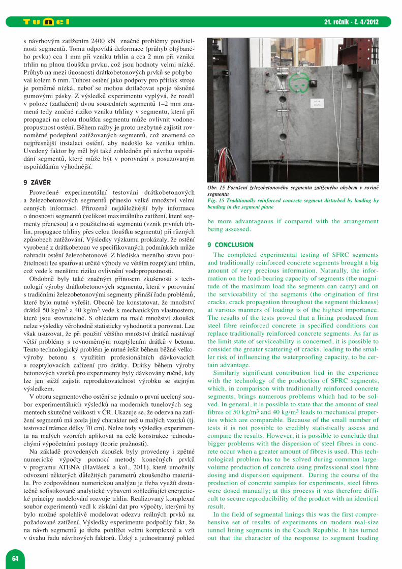
The above-mentioned tests were characterised by lowvalues of forces at which cracks started to originate. Thecracks localised themselves in the area above the box fora bolt and continued to extend downwards. It was possibleat the segments produced from steel fibre reinforced concre-te to observe the origination of numerous minute cracks; oneof them gradually opened and, subsequently, the load-carry-ing capacity got exhausted (see Figures 13 and 14). The tra-ditionally reinforced concrete segments were disturbed ina different way. One crack originated and started to open; itstarted to branch out only when a high load value was rea-ched (see Fig. 15). Failure limits were not reached, but theelement loaded in this way was completely unsatisfactory(with respect to the extension of cracks in the lining).
The character of the response of the tested materials to theloading was totally different, but the materials can be consi-dered to be comparable as far as the serviceability is concer-ned.
In general, it is possible to state in the case of both mate-rials that the segments are brittle and susceptible to fractu-ring even when loaded by small forces. The origination ofcracks at 300 kN and the propagation of cracks to throughoutthickness of the segment at 500 kN, if compared with thedesign load of 2400 kN, means significant problems with theserviceability of segments. The deformation (the deflectionof the element subjected to bending) of about 1 mm on theorigination of cracks and about 2 mm on the origination ofcracks running throughout the element thickness, whichvalues are very low, corresponds to this information. Thedeflection at the failure load of the SFRC elements variedaround 6 mm. The rigidity of the lining providing support forthe machine thrust forces is relatively low because the rub-ber gaskets sealing the joints can be subject to creeping. Itfollows from the results of the experiment that the differen-ce in the position (pushing in) of two neighbouring segmentsof 1-2 mm means significant risk of the origination ofa crack in the segment, which may affect the waterproofingcapacity of the lining in the case it propagates throughout thesegment thickness. It is therefore necessary during the cour-se of the excavation to secure uniform support of the seg-ments being subjected to loading, which means that thelining has to be installed as accurately as possible so that theorigination of cracks is prevented. In addition, the above-mentioned factor should be taken into consideration whenthe arrangement of segments is being designed – which can
dolů. U segmentů vyrobených z drátkobetonu bylo možnépozorovat vznik řady nepatrných trhlin, z nichž se jednapostupně rozevírala a následně došlo ke ztrátě únosnosti (obr.13 a 14). Železobenotové segmenty byly porušeny odlišně,vznikla jedna trhlina, která se rozevírala a začala se větvit tepr-ve při dosažení vysokého zatížení (obr. 15). Meze únosnostinebylo dosaženo, avšak takto zatížený prvek by byl zcelanevyhovující (s ohledem na rozevření trhlin v ostění).
Charakter odezvy na zatížení byl u zkoušených materiálůzcela odlišný, ovšem z hlediska použitelnosti lze považovatmateriály za srovnatelné.
Obecně lze v případě obou materiálů konstatovat, že seg-menty jsou křehké a náchylné na porušení již při nízkýchsilách. Vznik trhlin při 300 kN a propagace trhlin na plnoutloušťku segmentu při 500 kN znamená v porovnání
Obr. 13 a 14 Porušení drátkobetonového segmentu zatíženého ohybemv rovině segmentuFigures 13 and 14 Steel fibre reinforced concrete segment disturbed by loa-ding by bending in the segment plane
64
21. ročník - č. 4/2012
be more advantageous if compared with the arrangementbeing assessed.
9 CONCLUSION
The completed experimental testing of SFRC segmentsand traditionally reinforced concrete segments brought a bigamount of very precious information. Naturally, the infor-mation on the load-bearing capacity of segments (the magni-tude of the maximum load the segments can carry) and onthe serviceability of the segments (the origination of firstcracks, crack propagation throughout the segment thickness)at various manners of loading is of the highest importance.The results of the tests proved that a lining produced fromsteel fibre reinforced concrete in specified conditions canreplace traditionally reinforced concrete segments. As far asthe limit state of serviceability is concerned, it is possible toconsider the greater scattering of cracks, leading to the smal-ler risk of influencing the waterproofing capacity, to be cer-tain advantage.
Similarly significant contribution lied in the experiencewith the technology of the production of SFRC segments,which, in comparison with traditionally reinforced concretesegments, brings numerous problems which had to be sol-ved. In general, it is possible to state that the amount of steelfibres of 50 kg/m3 and 40 kg/m3 leads to mechanical proper-ties which are comparable. Because of the small number oftests it is not possible to credibly statistically assess andcompare the results. However, it is possible to conclude thatbigger problems with the dispersion of steel fibres in conc-rete occur when a greater amount of fibres is used. This tech-nological problem has to be solved during common large-volume production of concrete using professional steel fibredosing and dispersion equipment. During the course of theproduction of concrete samples for experiments, steel fibreswere dosed manually; at this process it was therefore diffi-cult to secure reproducibility of the product with an identicalresult.
In the field of segmental linings this was the first compre-hensive set of results of experiments on modern real-sizetunnel lining segments in the Czech Republic. It has turnedout that the character of the response to segment loading
s návrhovým zatížením 2400 kN značné problémy použitel-nosti segmentů. Tomu odpovídá deformace (průhyb ohýbané-ho prvku) cca 1 mm při vzniku trhlin a cca 2 mm při vznikutrhlin na plnou tloušťku prvku, což jsou hodnoty velmi nízké.Průhyb na mezi únosnosti drátkobetonových prvků se pohybo-val kolem 6 mm. Tuhost ostění jako podpory pro přítlak strojeje poměrně nízká, neboť se mohou dotlačovat spoje těsněnégumovými pásky. Z výsledků experimentu vyplývá, že rozdílv poloze (zatlačení) dvou sousedních segmentů 1–2 mm zna-mená tedy značné riziko vzniku trhliny v segmentu, která připropagaci na celou tloušťku segmentu může ovlivnit vodone-propustnost ostění. Během ražby je proto nezbytné zajistit rov-noměrné podepření zatěžovaných segmentů, což znamená conejpřesnější instalaci ostění, aby nedošlo ke vzniku trhlin.Uvedený faktor by měl být také zohledněn při návrhu uspořá-dání segmentů, které může být v porovnání s posuzovanýmuspořádáním výhodnější.
9 ZÁVĚR
Provedené experimentální testování drátkobetonovýcha železobetonových segmentů přineslo velké množství velmicenných informací. Přirozeně nejdůležitější byly informaceo únosnosti segmentů (velikost maximálního zatížení, které seg-menty přenesou) a o použitelnosti segmentů (vznik prvních trh-lin, propagace trhliny přes celou tloušťku segmentu) při různýchzpůsobech zatěžování. Výsledky výzkumu prokázaly, že ostěnívyrobené z drátkobetonu ve specifikovaných podmínkách můženahradit ostění železobetonové. Z hlediska mezního stavu pou-žitelnosti lze spatřovat určité výhody ve větším rozptýlení trhlin,což vede k menšímu riziku ovlivnění vodopropustnosti.
Obdobně byly také značným přínosem zkušenosti s tech -nologií výroby drátkobetonových segmentů, která v porovnánís tradičními železobetonovými segmenty přináší řadu problémů,které bylo nutné vyřešit. Obecně lze konstatovat, že množstvídrátků 50 kg/m3 a 40 kg/m3 vede k mechanickým vlastnostem,které jsou srovnatelné. S ohledem na malé množství zkoušeknelze výsledky věrohodně statisticky vyhodnotit a porovnat. Lzevšak usuzovat, že při použití většího množství drátků nastávajívětší problémy s rovnoměrným rozptýlením drátků v betonu.Tento technologický problém je nutné řešit během běžné velko-výroby betonu s využitím profesionálních dávkovacícha rozptylovacích zařízení pro drátky. Drátky během výrobybetonových vzorků pro experimenty byly dávkovány ručně, kdylze jen stěží zajistit reprodukovatelnost výrobku se stejnýmvýsledkem.
V oboru segmentového ostění se jednalo o první ucelený sou-bor experimentálních výsledků na moderních tunelových seg-mentech skutečné velikosti v ČR. Ukazuje se, že odezva na zatí-žení segmentů má zcela jiný charakter než u malých vzorků (tj.testovací trámce délky 70 cm). Nelze tedy výsledky experimen-tu na malých vzorcích aplikovat na celé konstrukce jednodu-chými výpočetními postupy (teorie pružnosti).
Na základě provedených zkoušek byly provedeny i zpětnénumerické výpočty pomocí metody konečných prvkův programu ATENA (Havlásek a kol., 2011), které umožnilyodvození některých důležitých parametrů zkoušeného materiá-lu. Pro zodpovědnou numerickou analýzu je třeba využít dosta-tečně sofistikované analytické vybavení zohledňující energetic-ké principy modelování rozvoje trhlin. Realizovaný komplexnísoubor experimentů vedl k získání dat pro výpočty, kterými bybylo možné spolehlivě modelovat odezvu reálných prvků napožadované zatížení. Výsledky experimentu podpořily fakt, žena návrh segmentů je třeba pohlížet velmi komplexně a vzítv úvahu řadu návrhových faktorů. Úzký a jednostranný pohled
Obr. 15 Porušení železobetonového segmentu zatíženého ohybem v roviněsegmentuFig. 15 Traditionally reinforced concrete segment disturbed by loading bybending in the segment plane
65
21. ročník - č. 4/2012
completely differs from the character determined in thecases of small samples (i.e. testing beams 70 cm long). It istherefore impossible to apply results of experiments on smallsamples to complete structures using simple calculation pro-cedures (the theory of elasticity).
Even backward calculations using the Finite ElementMethod in the ANTENA program (Havlásek et al., 2011)were carried out on the basis of the completed tests. Owingto them the deriving of some important parameters of testedmaterials was possible. A responsible numerical analysisrequires the use of sufficiently sophisticated analytical equ-ipment taking into account energetic principles of modellingthe development of cracks. The completed comprehensiveset of experiments led to the obtaining of data for calculati-ons which could be used for reliable modelling of the res-ponse of real elements to the required loading. The experi-ment results supported the fact that a segment design mustbe viewed in a very comprehensive manner and a range ofdesign factors must be taken into consideration. A narrowand one-sided view of the problems leads to neglecting ofsome influences, which may subsequently complicate theprocess of the execution of pre-cast tunnel lining and rea-ching required end-use properties of the lining.
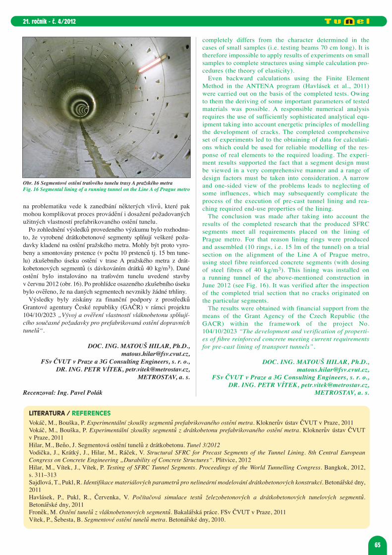
The conclusion was made after taking into account theresults of the completed research that the produced SFRCsegments meet all requirements placed on the lining ofPrague metro. For that reason lining rings were producedand assembled (10 rings, i.e. 15 lm of the tunnel) on a trialsection on the alignment of the Line A of Prague metro,using steel fibre reinforced concrete segments (with dosingof steel fibres of 40 kg/m3). This lining was installed ona running tunnel of the above-mentioned construction inJune 2012 (see Fig. 16). It was verified after the inspectionof the completed trial section that no cracks originated onthe particular segments.
The results were obtained with financial support from themeans of the Grant Agency of the Czech Republic (theGACR) within the framework of the project No.104/10/2023 “The development and verification of properti-es of fibre reinforced concrete meeting current requirementsfor pre-cast lining of transport tunnels”.
DOC. ING. MATOUŠ HILAR, Ph.D.,[email protected],
FSv ČVUT v Praze a 3G Consulting Engineers, s. r. o., DR. ING. PETR VÍTEK, [email protected],
METROSTAV, a. s.
LITERATURA / REFERENCES
Vokáč, M., Bouška, P. Experimentální zkoušky segmentů prefabrikovaného ostění metra. Kloknerův ústav ČVUT v Praze, 2011 Vokáč, M., Bouška, P. Experimentální zkoušky segmentů z drátkobetonu prefabrikovaného ostění metra. Kloknerův ústav ČVUTv Praze, 2011Hilar, M., Beňo, J. Segmentová ostění tunelů z drátkobetonu. Tunel 3/2012Vodička, J., Krátký, J., Hilar, M., Ráček, V. Structural SFRC for Precast Segments of the Tunnel Lining. 8th Central EuropeanCongress on Concrete Engineering „Durability of Concrete Structures“. Plitvice, 2012Hilar, M., Vítek, J., Vítek, P. Testing of SFRC Tunnel Segments. Proceedings of the World Tunnelling Congress. Bangkok, 2012,s. 311–313Sajdlová, T., Pukl, R. Identifikace materiálových parametrů pro nelineární modelování drátkobetonových konstrukcí. Betonářské dny,2011Havlásek, P., Pukl, R., Červenka, V. Počítačová simulace testů železobetonových a drátkobetonových tunelových segmentů.Betonářské dny, 2011Froněk, M. Ostění tunelů z vláknobetonových segmentů. Bakalářská práce. FSv ČVUT v Praze, 2011Vítek, P., Šebesta, B. Segmentové ostění tunelů metra. Betonářské dny, 2010.
Obr. 16 Segmentové ostění traťového tunelu trasy A pražského metraFig. 16 Segmental lining of a running tunnel on the Line A of Prague metro
na problematiku vede k zanedbání některých vlivů, které pakmohou komplikovat proces provádění i dosažení požadovanýchužitných vlastností prefabrikovaného ostění tunelu.
Po zohlednění výsledků provedeného výzkumu bylo rozhodnu-to, že vyrobené drátkobetonové segmenty splňují veškeré poža-davky kladené na ostění pražského metra. Mohly být proto vyro-beny a smontovány prstence (v počtu 10 prstenců tj. 15 bm tune-lu) zkušebního úseku ostění v trase A pražského metra z drát -kobetonových segmentů (s dávkováním drátků 40 kg/m3). Danéostění bylo instalováno na traťovém tunelu uvedené stavbyv červnu 2012 (obr. 16). Po prohlídce osazeného zkušebního úsekubylo ověřeno, že na daných segmentech nevznikly žádné trhliny.
Výsledky byly získány za finanční podpory z prostředkůGrantové agentury České republiky (GAČR) v rámci projektu104/10/2023 „Vývoj a ověření vlastností vláknobetonu splňují-cího současné požadavky pro prefabrikovaná ostění dopravníchtunelů“.
DOC. ING. MATOUŠ HILAR, Ph.D.,[email protected],
FSv ČVUT v Praze a 3G Consulting Engineers, s. r. o., DR. ING. PETR VÍTEK, [email protected],
METROSTAV, a. s.
Recenzoval: Ing. Pavel Polák