Embed Size (px)
Citation preview
RESEARCH Open Access
Experiments and assessments of a 3-DOFhaptic device for interactive operationHuijun Li*, Aiguo Song, Bowei Li, Baoguo Xu and Hong Zeng
Abstract
Haptic devices have been applied in interactive operation to perform contact tasks. To explore the haptic perceptioncharacteristics of typical push-pull and rotation operation, an experimental system was built by incorporating a threedegrees of freedom (3-DOF) haptic device and the virtual environment. In this system, the haptic device is used toprovide motion commands to control the avatar in the virtual environment and to exert haptic feedback on thehuman operator generated by three motors. In order to evaluate the main influential factors of interactive systembased on haptic devices, ergonomic assessments are designed and experimentally implemented. Preliminary studieson the factors including restoring force, guidance force, speed of the virtual avatar, and the arm length have beenconducted. The results are of great significance for the design of a haptic device and haptic interaction system byanalyzing the specific requirements of ergonomics.
Keywords: Haptic device, Haptic feedback, Interactive operation, Ergonomics assessments
1 IntroductionThe development of many applications of interactive oper-ation requires flexible haptic master to perform contacttasks. These tasks include interaction with computer-aideddesign models, telerobotic surgery, micro/nano-manipula-tion, undersea salvage, and space telerobotic explorationand maintenance, decontamination, and decommissioningof chemical and nuclear facilities [1, 2].The execution of these tasks by a human operator is
affected by his/her level of perception of the interactionobjects [3]. This perception can be enhanced by audio,visual, and haptic cues. While visual cues are certainlymandatory and audio cues beneficial at times, hapticcues can significantly improve the flow of informationfrom the environment to the human operator for manytasks requiring dexterity [4]. Haptic devices are the mostpopular devices to provide haptic feedback in interactivemanipulations. As a medium between environments andhuman users, haptic interfaces transmit and display hap-tic stimuli [5]. With precisely controlled forces and tor-ques exerted on the manipulator’s fingertips, hand, orarm, subtle sensations are able to be perceived, thus ahigh level of immersion is constructed. In the past
decades, several types of haptic master devices featuringthe feedback function have been proposed, some ofwhich are commercially available devices and some areexperimental prototypes [6, 7]. The PHANToM, whichis the most commonly used haptic device, can generateforce feedback along six degrees of freedom (6-DOF)motions using motors [8]. The Xitack IHP of XitackSA, which has been proposed for virtual reality applica-tions, has 4-DOF force feedback functions [9]. With theDual ArmWork Platform (DAWP) at Argonne NationalLaboratory [10], one of the key improvements theCobotic Hand Controller can provide to DAWP oper-ation is the implementation of virtual surfaces, or vir-tual constraints on motion, as suggested by Faulring[11]. Such haptic devices can reproduce the constraintsor guidance and can vastly simplify execution of a con-tact task. While guidance or constraints can be imple-mented in the existing system, an active haptic deviceallows for the reproduction of these guidance or con-straints for the human operator and may reduce opera-tor’s fatigue while increasing efficiency by eliminatingunneeded or wrong motions in workspace. Large im-provements on existing devices can only be achieved bya proper match between the performance of the deviceand human haptic abilities. To find out how the userscan complete the operation with a haptic device by
* Correspondence: [email protected]; [email protected] of Instrument Science and Engineering, Southeast University, Nanjing210096, China
EURASIP Journal on Imageand Video Processing
© The Author(s). 2018 Open Access This article is distributed under the terms of the Creative Commons Attribution 4.0International License (http://creativecommons.org/licenses/by/4.0/), which permits unrestricted use, distribution, andreproduction in any medium, provided you give appropriate credit to the original author(s) and the source, provide a link tothe Creative Commons license, and indicate if changes were made.
Li et al. EURASIP Journal on Image and Video Processing (2018) 2018:94 https://doi.org/10.1186/s13640-018-0331-5

creating synthetic haptic experiences, quantitative hu-man studies should be carried out. To determine thenature of these approximations, or, in other words, tofind out what we can get away with in creating syn-thetic haptic experiences, ergonomics studies are essen-tial. Understanding of such influencing factors as theguidance force, the reset force, the speed of the virtualavatar, and the arm length is critical for proper designspecification of the hardware and software of hapticinterfaces.Current trend in design of haptic masters is to meet
the need for designs with safety, high performance, suf-ficient workspace, enough force and torque, high stiff-ness, and small inertia [12–14]. By their nature, hapticdevices operate in contact with a human operator.Greater research effort on the operator’s perceptionand overall performance using the haptic devices couldaccelerate the development of haptic interaction tech-nology [15–17]. In these researches, the haptic percep-tion of the users was optimized and evaluated usinghaptic devices. Human factors as well as others thataffect the design specifications of force-reflecting hapticinterfaces were also of a concern [18].In this paper, we introduced a novel three degrees of
freedom (3-DOF) haptic device. Concerned with quanti-tative measures of influencing factors that affect theoverall performance, the design specifications of hapticinteraction system are presented. The remainder of thepaper is organized as follows. Mechanical design andkinematical analysis of the haptic device are presentedin Section 2. Construction of a haptic interaction sys-tem based on the proposed haptic device is presentedin Section 3. Experimental method and constructionare presented in Section 4, and the performance of theproposed system is verified experimentally in Section 5.The paper is then concluded in Section 6.
2 Three DOF haptic device2.1 Mechanical designMechanical design of haptic devices is to meet the needfor designs with sufficient workspace, enough force and
torque, high stiffness, small inertia, and mechanical de-coupling. However, some of these requirements, suchas large stiffness and small inertia, are conflicting in nature[19, 20]. Due to the multi-criteria and multi-domain func-tional and performance requirements of high-performinghaptic devices, it is not sufficient to develop such a deviceby sub-optimizing the requirements from each separatediscipline. The main design objectives of our device are toobtain a large workspace and mechanical decoupling and,at the same time, provide enough torque feedback. Aparallel haptic device for interactive operation is de-signed which mainly consists of three mutually orthog-onal translational axes that have lower inertia andbetter stiffness. The assembly drawing of this device ispresented in Fig. 1.The haptic device mainly consists of the base, the
cuboid frame and cylindrical sleeve, the handle, threeactuators, and photoelectric encoders. The proposedstructure is similar to a three-axis gyroscope in whichthree axes are orthogonal and intersect at a fixed point(coordinate origin). The cuboid frame is mounted hori-zontally on the base and can be rotated around the X-axis.The cylindrical sleeve is mounted vertically to be rotatedaround the Y-axis. The handle is mounted coaxial with theZ-axis actuator in the cylindrical sleeve and can be rotatedaround the Z-axis. In this way, each kinematic freedom isindependent and there is no motion interference whichmeans kinematic coupling is mechanically avoided.While haptic devices usually work at a low speed
and provide high torque, corresponding reducers areequipped to increase the output torque and to reducethe rotational speed. Three DC motors manufacturedby Maxon Corporation are used to generate the force/torque feedback. The device is capable of rendering con-tinuous forces up to 25 N in the X- and Y-axes and torqueof 0.5 Nm around the Z-axis.
2.2 Kinematics analysisThe kinematic diagram of the designed haptic device isdescribed in Fig. 2. The motion of the haptic device toany point in the workspace can be decomposed into
Fig. 1 Assembly drawing of the haptic device. (1) Base. (2) Cuboid frame. (3) Handle. (4) Bevel gears. (5) Y-axis actuator. (6) X-axis actuator. (7)Cylinder sleeve with Z-axis actuator. (8) Mounting holes for restoring rubber bands. (9) Restoring torsion spring
Li et al. EURASIP Journal on Image and Video Processing (2018) 2018:94 Page 2 of 15
motion components on x-o-z plane and y-o-z planerespectively.Assuming that the length of the handle bar is l (from
the intersection point to the end of the handle), the rota-tion angle around the Z-axis is θ3, and the rotation an-gles on the x-o-z plane and y-o-z plane are θ1 and θ2respectively, the coordinate of the end of the handle is P(Px, Py, Pz), then the relationship between the coordin-ate of the end P, the length of the handle bar l, and therotation angles of the handle is (ignoring minor deform-ation of the bar),
Px ¼ l � tanθ1ffiffiffiffiffiffiffiffiffiffiffiffiffiffiffiffiffiffiffiffiffiffiffiffiffiffiffiffiffiffiffiffiffiffiffiffiffiffiffiffiffiffiffiffiffiffiffiffiffiffiffi
1þ tanθ1ð Þ2 þ tanθ2ð Þ2q ð1Þ
Py ¼ l � tanθ2ffiffiffiffiffiffiffiffiffiffiffiffiffiffiffiffiffiffiffiffiffiffiffiffiffiffiffiffiffiffiffiffiffiffiffiffiffiffiffiffiffiffiffiffiffiffiffiffiffiffiffi
1þ tanθ1ð Þ2 þ tanθ2ð Þ2q ð2Þ
Pz ¼ lffiffiffiffiffiffiffiffiffiffiffiffiffiffiffiffiffiffiffiffiffiffiffiffiffiffiffiffiffiffiffiffiffiffiffiffiffiffiffiffiffiffiffiffiffiffiffiffiffiffiffi
1þ tanθ1ð Þ2 þ tanθ2ð Þ2q ð3Þ
θ3 ¼ θ3 ð4Þ
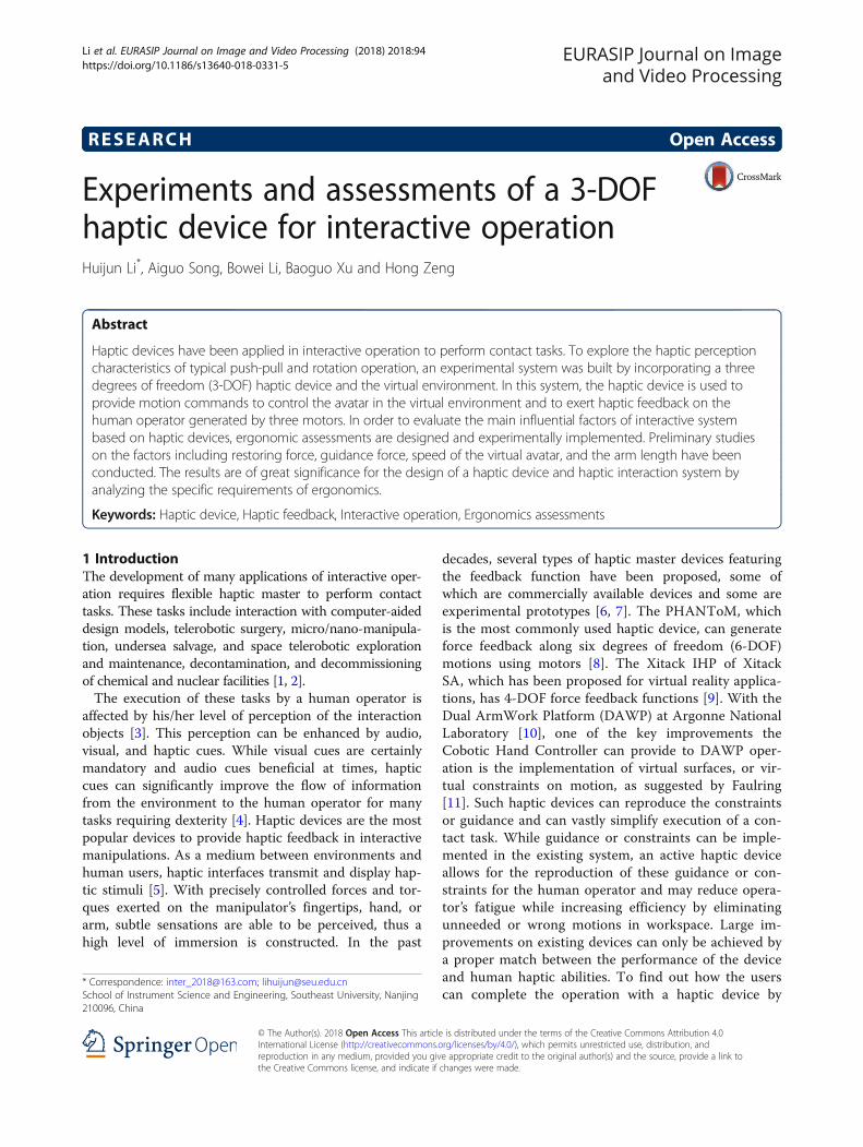
The rotational ranges of the haptic device about theX-, Y-, Z-axes are designed as − 60°~60°, − 60°~ 60°, and− 90°~ 90° respectively and the distance from the centerof rotation to the end of the handle is 150 mm, so themotion space of the haptic device can be deduced to bea spherical surface from formula (1–3) and its work-space is up to 259.72 mm × 259.72 mm × 93.30 mm, asis drawn in Matlab as Fig. 3.
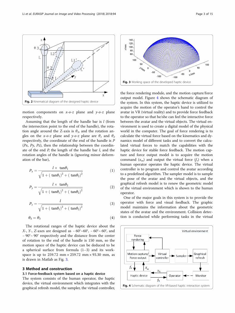
3 Method and construction3.1 Force-feedback system based on a haptic deviceThe system consists of the human operator, the hapticdevice, the virtual environment which integrates with thegraphical refresh model, the sampler, the virtual controller,
the force rendering module, and the motion capture/forceoutput model. Figure 4 shows the schematic diagram ofthe system. In this system, the haptic device is utilized toacquire the motion of the operator’s hand to control theavatar in VR (virtual reality) and to provide force feedbackto the operator so that he/she can feel the interactive forcebetween the avatar and the virtual objects. The virtual en-vironment is used to create a digital model of the physicalworld in the computer. The goal of force rendering is tocalculate the virtual force based on the kinematics and dy-namics model of different tasks and to convert the calcu-lated virtual forces to match the capabilities with thehaptic device for stable force feedback. The motion cap-ture and force output model is to acquire the motioncommand (xm) and output the virtual force (fv) when ahuman operator operates the haptic device. The virtualcontroller is to program and control the avatar accordingto a predefined algorithm. The sampler model is to samplethe pose of the avatar and the virtual objects, and thegraphical refresh model is to renew the geometric modelof the virtual environment which is shown to the humanoperator.One of the major goals in this system is to provide the
operator with force and visual feedback. The graphicmodel maintains the information about the geometricstates of the avatar and the environment. Collision detec-tion is conducted while performing tasks in the virtual
Fig. 2 Kinematical diagram of the designed haptic device
Fig. 3 Working space of the developed haptic device
Fig. 4 Schematic diagram of the VR-based haptic interaction system
Li et al. EURASIP Journal on Image and Video Processing (2018) 2018:94 Page 3 of 15
environment. This allows the virtual objects to deformand give counterforce to the avatar. This force generatedin the virtual environment exerts on the operator at thesame time. Then the operator holding the haptic devicefeels the counterforce acting on the avatar and watchesthe motion of the virtual objects on the screen. The com-bination of visual and force feedback makes the operatorfeel the interaction of the virtual objects.In order to improve the frequency of force feedback,
the virtual environment module is divided into twoloops, one is for visual display and the other is for forcefeedback. Since the two loops can be processed inde-pendently, the virtual force can be rendered at a highfrequency of 500~1 kHz to ensure the continuity andstable perception for the human operator. The graphicsrefresh loop is to complete the collision detection andthe collision response (including deformation calcula-tion and graphics rendering) at a lower frequency oftens of hertz.
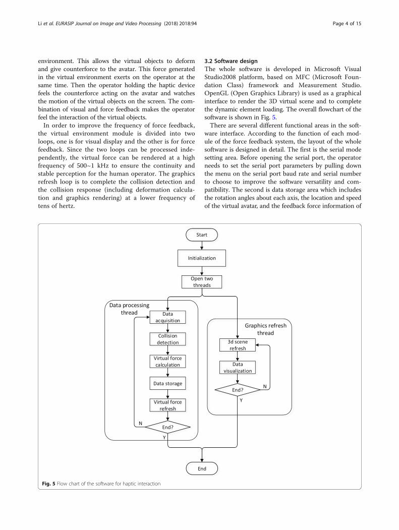
3.2 Software designThe whole software is developed in Microsoft VisualStudio2008 platform, based on MFC (Microsoft Foun-dation Class) framework and Measurement Studio.OpenGL (Open Graphics Library) is used as a graphicalinterface to render the 3D virtual scene and to completethe dynamic element loading. The overall flowchart of thesoftware is shown in Fig. 5.There are several different functional areas in the soft-
ware interface. According to the function of each mod-ule of the force feedback system, the layout of the wholesoftware is designed in detail. The first is the serial modesetting area. Before opening the serial port, the operatorneeds to set the serial port parameters by pulling downthe menu on the serial port baud rate and serial numberto choose to improve the software versatility and com-patibility. The second is data storage area which includesthe rotation angles about each axis, the location and speedof the virtual avatar, and the feedback force information of
Fig. 5 Flow chart of the software for haptic interaction
Li et al. EURASIP Journal on Image and Video Processing (2018) 2018:94 Page 4 of 15
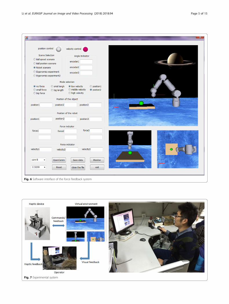
Fig. 6 Software interface of the force feedback system
Fig. 7 Experimental system
Li et al. EURASIP Journal on Image and Video Processing (2018) 2018:94 Page 5 of 15
each degree of freedom. The third is data visualizationarea. In order to understand the feedback information inreal time intuitively, the operator can click the monitorbutton to pop up a new window to display the three de-grees of freedom and virtual force feedback in dials and
waveforms. The fourth is virtual scene selection area.Three different virtual environments are designed in thesoftware, namely the flexible ball scene model, virtual ro-botic task scene, and ball tracking scene. The operator canswitch according to their own needs to operate in the
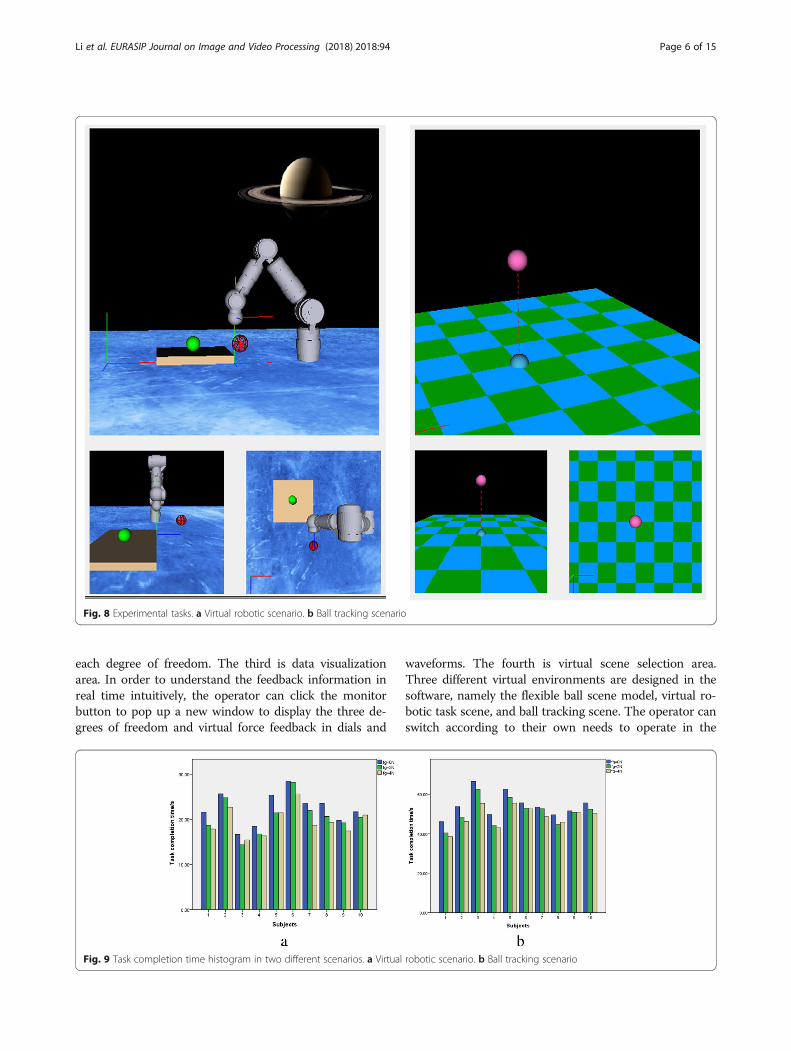
Fig. 8 Experimental tasks. a Virtual robotic scenario. b Ball tracking scenario
Fig. 9 Task completion time histogram in two different scenarios. a Virtual robotic scenario. b Ball tracking scenario
Li et al. EURASIP Journal on Image and Video Processing (2018) 2018:94 Page 6 of 15
corresponding scenario. The last is operation mode selec-tion area. The haptic device can be used for position con-trol or speed control. The operator can quickly switchbetween the position control mode and the speed controlmode in this area. The overall software interface is shownin Fig. 6.
4 Experimental results and discussion4.1 Experimental systemThe haptic device is mainly used in the field of VR-basedinteraction to acquire the motion of the operator’s handand to provide the operator with force feedback. As aman-machine interface, not only mechanical but alsoergonomic characters are important. Parameters of thehaptic device such as the restoration force, the operatingspeed, and the guidance force will directly affect the com-fort and efficiency, so understanding of the operator’s op-erating habits is necessary to design a haptic device that isefficient, comfortable, and in line with people’s operatinghabits. In order to experimentally evaluate the influence ofthe design parameters, we built a prototype of VR-basedhaptic interaction system. Several ergonomic experimentsare designed and performed. Effective data collected is uti-lized to statistically analyze the characteristics and effi-ciency while operating with the developed haptic device.The experimental system consists of the developed
haptic device, the virtual environment, and the operator,as shown in Fig. 7. The operator can control the avatarand sense the force feedback of the virtual environment,
Table 1 Average Task Completion Time (Second)
Subjects Virtual robotic scenario Ball tracking scenario
fg = 0 N fg = 2 N fg = 4 N fg = 0 N fg = 2 N fg = 4 N
1 21.625 18.633 17.846 46.157 40.492 38.491
2 25.648 24.765 22.694 53.719 48.468 46.189
3 16.654 14.369 15.432 66.492 62.483 55.371
4 18.462 16.751 16.345 49.755 44.392 43.034
5 25.349 21.459 21.469 62.449 58.428 55.482
6 28.394 28.200 25.624 55.664 52.983 52.648
7 23.462 21.954 18.694 53.469 52.694 48.691
8 23.489 20.645 19.369 49.648 44.669 45.893
9 19.762 19.239 17.425 51.673 50.945 50.694
10 21.694 20.469 20.964 55.644 52.469 50.442
Table 2 Analysis of variance the maximum operating angle in six movement directions
Sum of the squares df Mean square F Significance
X+ (°)
Inter-group 279.912 2 139.956 4.651 0.018
Intra-group 812.525 27 30.094
Sum 1092.437 29
X− (°)
Inter-group 526.287 2 263.144 6.465 0.005
Intra-group 1099.021 27 40.704
Sum 1625.308 29
Y+ (°)
Inter-group 473.750 2 236.875 10.219 0.000
Intra-group 625.872 27 23.180
Sum 1099.622 29
Y− (°)
Inter-group 836.978 2 418.489 5.376 0.011
Intra-group 2101.904 27 77.848
Sum 2938.882 29
Z+ (°)
Inter-group 1769.057 2 884.528 6.194 0.006
Intra-group 3855.782 27 142.807
Sum 5624.839 29
Z− (°)
Inter-group 1160.788 2 580.394 2.300 0.120
Intra-group 6814.036 27 252.372
Sum 7974.824 29
X+ means the positive direction of X-axis, X− means the negative direction of X-axis. The rest in the same way
Li et al. EURASIP Journal on Image and Video Processing (2018) 2018:94 Page 7 of 15
such as contact force, frictional force, and guidanceforce, through the haptic device.
4.2 Experimental tasksIn this study, we mainly analyze several factors whichplay a significant role in the haptic interaction system,including the guidance force, the restoration force, theoperating speed, and the arm length. Ten healthy volun-teers aged 20–30 years (habitual use of the right hand)participated in the experiments. The experiments consistof two parts. The first part is the virtual robotic task sce-nario shown as Fig. 8a which is designed to test the typ-ical operation of grasping and releasing. In this taskscenario, the operator should control the virtual armthrough the haptic device to grasp the green ball on theyellow plane, then move it to the red ball and release.Catching or releasing the ball is switched by the button
on the handle of the haptic device. In this experiment,no guidance is provided and the operator should plantheir own path according to the information available.The second part is a ball tracking scenario shown inFig. 9b which is designed to test the typical operation oftrajectory tracking. This is a path-guided operationaltask. The operator should control the blue ball throughthe haptic device to track the pink ball following thepreset path. Once the blue ball touched the pink ball,the latter moved to the next positon and the operatorshould go on tracking. The entire process consists of sixsuch cycles.A variable-controlling approach is applied in the ex-
periment to analyze the effects of each factor on theinteractive operation. The first factor is the guidanceforce (fg) provided by the motors to guide the operatorto move toward the target. Suppose the guidance force
a b
c d
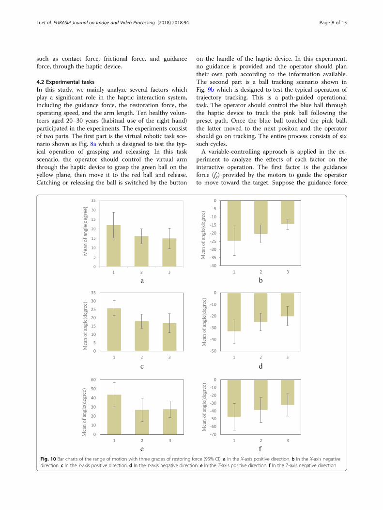
e fFig. 10 Bar charts of the range of motion with three grades of restoring force (95% CI). a In the X-axis positive direction. b In the X-axis negativedirection. c In the Y-axis positive direction. d In the Y-axis negative direction. e In the Z-axis positive direction. f In the Z-axis negative direction
Li et al. EURASIP Journal on Image and Video Processing (2018) 2018:94 Page 8 of 15
of 0 N, 2 N, and 4 N is for conditions a1, a2, and a3 re-spectively. The second factor is the restoration force (fr)exerted by the motors which drives the haptic deviceback to the originating pose after operating or in thenon-operating state. Suppose the restoration force of0 N, 2 N, and 4 N is for conditions b1, b2, and b3 re-spectively. The third is the speed of the virtual avatarwhich is set at 0.5 cm/s, 1.5 cm/s, and 2.5 cm/s for con-ditions c1, c2, and c3 respectively.Among all these control factors, a1, b1, and c2 are
the default control factors. During the experiments,when the influence of a variable is studied, the con-trol factor of this variable is changed, and other vari-ables are the default factors. For example, threegroups of experiments under conditions of a1 × b1 ×c2, a2 × b1 × c2, and a3 × b1 × c2 should be carriedout to study the effect of the guidance force in thevirtual robotic scenario and the ball tracking scenariorespectively. So each subject needs to do 18
experiments, and the experimental sequences of eachsubject were randomly arranged.
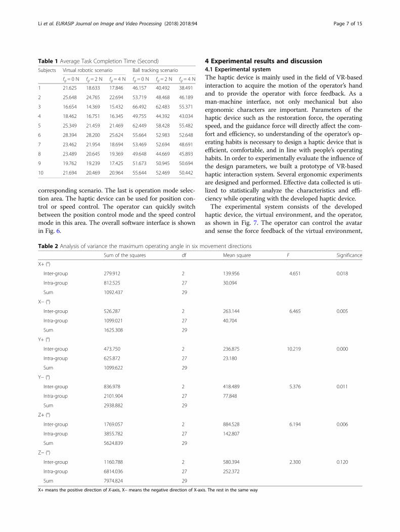
5 Results and analysis5.1 Effects of the guidance forceIn order to investigate the influence of the guidanceforce on the operation efficiency of the interactive sys-tem, three levels of 0 N, 2 N, and 4 N were applied inthe experiment. The average time for completing the de-signed task was recorded, as is shown in Table 1.According to the statistical data in Table 1, a task
completion time histogram of each operator with threelevels of guidance force in two scenarios is shown inFig. 9.As can be seen from Fig. 9, the overall distribution
of task completion time in three cases is consistentalthough the task completion time of ten subjects isslightly different. The guidance force will shorten thetask completion time in both two scenarios. In the
a b
c d
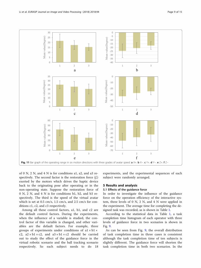
e fFig. 11 Bar graph of the operating range in six motion directions with three grades of avatar speed. a X+. b X−. c Y+. d Y−. e Z+. f Z−
Li et al. EURASIP Journal on Image and Video Processing (2018) 2018:94 Page 9 of 15
case of the virtual robot scenario, task completiontime was reduced by 15.3% at most and 8% on aver-age with 2 N guidance force compared with no guid-ance force. When 4 N guidance force was available,task completion time was shortened by 20.3% atmost and 12.7% on average. In the ball tracking sce-nario, task completion time reduction was 10.77% atmost and 6.7% on average with 2 N guidance forcecompared with no guidance force. When 4 N guide
force was available, task completion time was short-ened by 16.60% at most and 10.6% on average. Theresult indicates that the guidance force can give theoperator helpful hint to improve the operation effi-ciency and to shorten the task completion time. Al-though task completion time is averagely shortenedwith 4 N guide force compared with 2 N guide force,further experiments should be carried out to studythe optimal guidance force for different subjects anddifferent tasks.
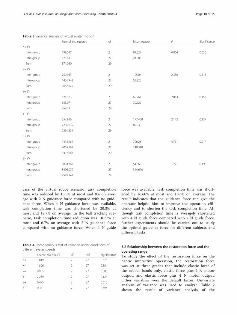
5.2 Relationship between the restoration force and theoperating rangeTo study the effect of the restoration force on thehaptic interactive operation, the restoration forcewas set at three grades that include elastic force ofthe rubber bands only, elastic force plus 2 N motoroutput, and elastic force plus 4 N motor output.Other variables were the default factor. Univariateanalysis of variance was used to analyze. Table 2shows the result of variance analysis of the
Table 3 Variance analysis of virtual avatar motion
Sum of the squares df Mean square F Significance
X+ (°)
Inter-group 199.247 2 99.624 4.004 0.030
Intra-group 671.833 27 24.883
Sum 871.080 29
X− (°)
Inter-group 250.083 2 125.041 2.350 0.115
Intra-group 1436.942 27 53.220
Sum 1687.025 29
Y+ (°)
Inter-group 124.523 2 62.261 2.013 0.153
Intra-group 835.071 27 30.929
Sum 959.593 29
Y− (°)
Inter-group 354.916 2 177.458 2.142 0.137
Intra-group 2236.635 27 82.838
Sum 2591.551 29
Z+ (°)
Inter-group 1412.462 2 706.231 4.761 0.017
Intra-group 4005.187 27 148.340
Sum 5417.648 29
Z− (°)
Inter-group 1083.262 2 541.631 1.721 0.198
Intra-group 8496.079 27 314.670
Sum 9579.341 29
Table 4 Homogeneous test of variance under conditions ofdifferent avatar speeds
Levene statistic (°) df1 df2 Significance
X+ 1.019 2 27 0.375
X− 1.806 2 27 0.184
Y+ 0.985 2 27 0.386
Y− 2.259 2 27 0.124
Z+ 0.495 2 27 0.615
Z− 0.371 2 27 0.694
Li et al. EURASIP Journal on Image and Video Processing (2018) 2018:94 Page 10 of 15
maximum operating angle (in degree) in three de-grees of freedom.In the result of the variance analysis given in Table 2,
the sum of the squared variance, the mean square, the Fvalue, and the probability P of the groups are given. Itcan be seen from the significance level P < 0.05 that
there was a significant difference in the mean value be-tween groups in the positive and negative directions ofthe X- and Y-axes and the positive direction of theZ-axis at the 0.05 level.Figure 10 shows the histogram of the range of the
movement of the hand in the positive and negative
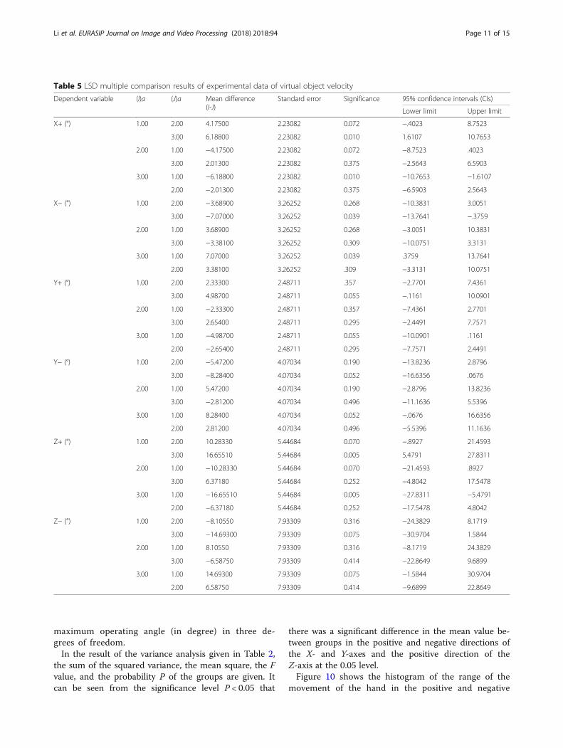
Table 5 LSD multiple comparison results of experimental data of virtual object velocity
Dependent variable (I)a (J)a Mean difference(I-J)
Standard error Significance 95% confidence intervals (CIs)
Lower limit Upper limit
X+ (°) 1.00 2.00 4.17500 2.23082 0.072 −.4023 8.7523
3.00 6.18800 2.23082 0.010 1.6107 10.7653
2.00 1.00 −4.17500 2.23082 0.072 −8.7523 .4023
3.00 2.01300 2.23082 0.375 −2.5643 6.5903
3.00 1.00 −6.18800 2.23082 0.010 −10.7653 −1.6107
2.00 −2.01300 2.23082 0.375 −6.5903 2.5643
X− (°) 1.00 2.00 −3.68900 3.26252 0.268 −10.3831 3.0051
3.00 −7.07000 3.26252 0.039 −13.7641 −.3759
2.00 1.00 3.68900 3.26252 0.268 −3.0051 10.3831
3.00 −3.38100 3.26252 0.309 −10.0751 3.3131
3.00 1.00 7.07000 3.26252 0.039 .3759 13.7641
2.00 3.38100 3.26252 .309 −3.3131 10.0751
Y+ (°) 1.00 2.00 2.33300 2.48711 .357 −2.7701 7.4361
3.00 4.98700 2.48711 0.055 −.1161 10.0901
2.00 1.00 −2.33300 2.48711 0.357 −7.4361 2.7701
3.00 2.65400 2.48711 0.295 −2.4491 7.7571
3.00 1.00 −4.98700 2.48711 0.055 −10.0901 .1161
2.00 −2.65400 2.48711 0.295 −7.7571 2.4491
Y− (°) 1.00 2.00 −5.47200 4.07034 0.190 −13.8236 2.8796
3.00 −8.28400 4.07034 0.052 −16.6356 .0676
2.00 1.00 5.47200 4.07034 0.190 −2.8796 13.8236
3.00 −2.81200 4.07034 0.496 −11.1636 5.5396
3.00 1.00 8.28400 4.07034 0.052 −.0676 16.6356
2.00 2.81200 4.07034 0.496 −5.5396 11.1636
Z+ (°) 1.00 2.00 10.28330 5.44684 0.070 −.8927 21.4593
3.00 16.65510 5.44684 0.005 5.4791 27.8311
2.00 1.00 −10.28330 5.44684 0.070 −21.4593 .8927
3.00 6.37180 5.44684 0.252 −4.8042 17.5478
3.00 1.00 −16.65510 5.44684 0.005 −27.8311 −5.4791
2.00 −6.37180 5.44684 0.252 −17.5478 4.8042
Z− (°) 1.00 2.00 −8.10550 7.93309 0.316 −24.3829 8.1719
3.00 −14.69300 7.93309 0.075 −30.9704 1.5844
2.00 1.00 8.10550 7.93309 0.316 −8.1719 24.3829
3.00 −6.58750 7.93309 0.414 −22.8649 9.6899
3.00 1.00 14.69300 7.93309 0.075 −1.5844 30.9704
2.00 6.58750 7.93309 0.414 −9.6899 22.8649
Li et al. EURASIP Journal on Image and Video Processing (2018) 2018:94 Page 11 of 15
directions of the X, Y, and Z under the conditions ofthree grades of restoration force. The abscissa inFig. 11 is 1, 2, and 3, representing the motor restor-ation force of 0 N, 2 N, and 4 N respectively and thevertical axis represents the maximum motion range indegree (°).As can be seen from Fig. 10, the restoration force has
an important effect on the operating range of the hapticdevice in all directions. The greater the restoration force,the smaller the corresponding operating range. This ispossibly because the restoration force constraints thefree motion of the operator to some extent. So the res-toration force should be minimized in the condition thatthe restoration is ensured.
5.3 Relationship between the speed of the avatar and theoperating rangeIn this experiment, the speed of the virtual avatar is setat 0.5 cm/s, 1.5 cm/s, and 2.5 cm/s respectively and theother factors are set as default factors. Three groups ofthe operable range were recorded in degree (°) andone-way analysis of variance (ANOVA) was used tostudy the effects of different conditions. The results areshown in Table 3.It can be seen from the significance level (P < 0.05)
that the intra-group means along X-axis positive dir-ection and Z-axis positive direction are significantlydifferent (P < 0.05) while the differences in other di-rections are not significant. Furthermore, the differ-ences of the measurement data were compared withthe homogeneity test of variances, and the results in-dicated there was no significant difference between
the variance of each group at the 0.05 level; that is,the variance is homogeneous, as is shown in Table 4.Least significant difference (LSD) multiple compari-
son procedure was used for further analysis. InTable 5, the experimental mean values were comparedwhile the avatar in VR moved at different speeds.When the significance level was less than 0.05, therewas a significant difference between the two groups.The results show that there is a significant differencein operating range in the six directions when the vir-tual object moved at the lowest speed and the highestspeed, which indicates that the speed of the virtualobject has an effect on the amplitude of the hapticdevice.Figure 11 shows the histogram of the operating
range of the haptic device in the positive and negativedirections of X, Y, and Z-axis under the conditions ofthree grades of avatar speed. The abscissa in Fig. 12is 1, 2, and 3, representing the avatar speed of0.5 cm/s, 1.5 cm/s, and 2.5 cm/s respectively. Thevertical axis represents the maximum operating anglein degrees in the corresponding direction.It can be seen from Fig. 11 that the moving speed of the
virtual avatar has a certain influence on the operatingrange in each direction. The larger the moving speed, thesmaller the operating range in the corresponding motiondirection.
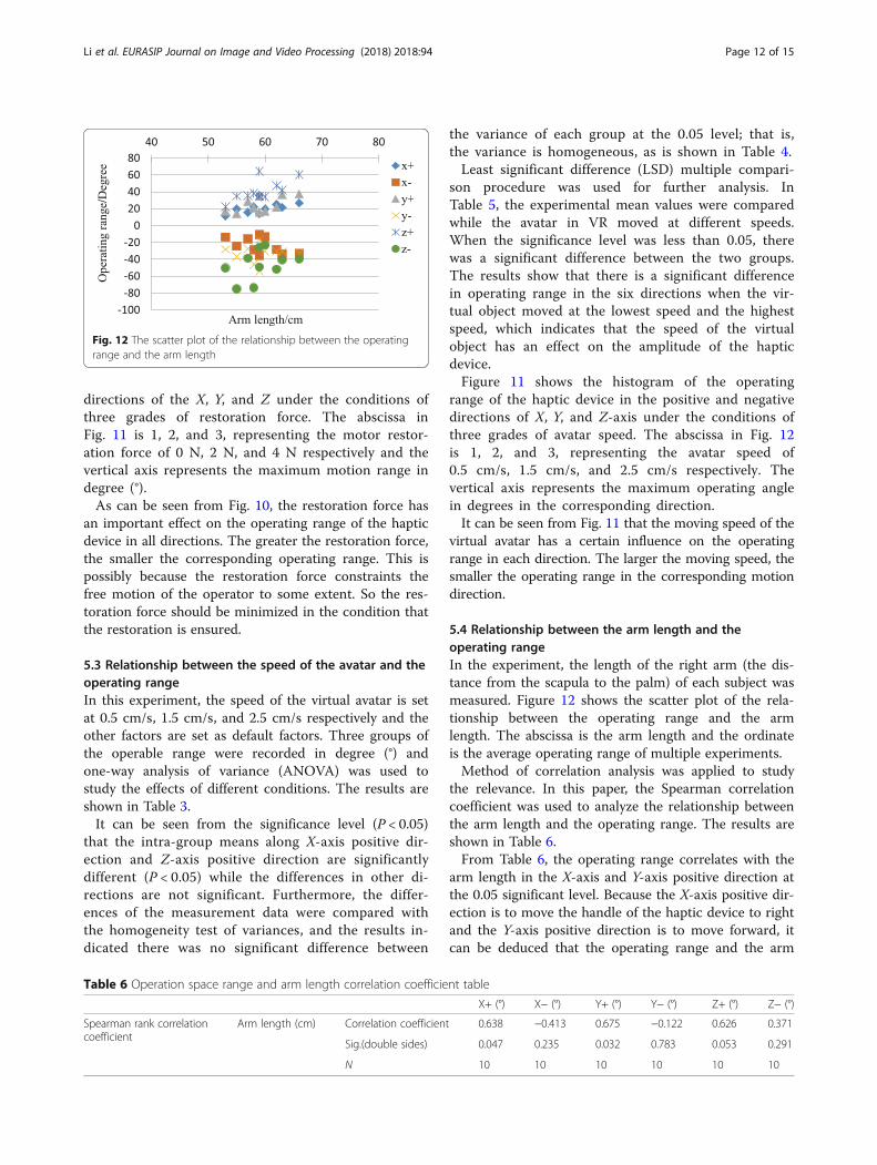
5.4 Relationship between the arm length and theoperating rangeIn the experiment, the length of the right arm (the dis-tance from the scapula to the palm) of each subject wasmeasured. Figure 12 shows the scatter plot of the rela-tionship between the operating range and the armlength. The abscissa is the arm length and the ordinateis the average operating range of multiple experiments.Method of correlation analysis was applied to study
the relevance. In this paper, the Spearman correlationcoefficient was used to analyze the relationship betweenthe arm length and the operating range. The results areshown in Table 6.From Table 6, the operating range correlates with the
arm length in the X-axis and Y-axis positive direction atthe 0.05 significant level. Because the X-axis positive dir-ection is to move the handle of the haptic device to rightand the Y-axis positive direction is to move forward, itcan be deduced that the operating range and the arm
Fig. 12 The scatter plot of the relationship between the operatingrange and the arm length
Table 6 Operation space range and arm length correlation coefficient table
X+ (°) X− (°) Y+ (°) Y− (°) Z+ (°) Z− (°)
Spearman rank correlationcoefficient
Arm length (cm) Correlation coefficient 0.638 −0.413 0.675 −0.122 0.626 0.371
Sig.(double sides) 0.047 0.235 0.032 0.783 0.053 0.291
N 10 10 10 10 10 10
Li et al. EURASIP Journal on Image and Video Processing (2018) 2018:94 Page 12 of 15
length are positively correlated when the handle ismoved away from the body and the correlation coeffi-cients are 0.638 and 0.655 respectively.
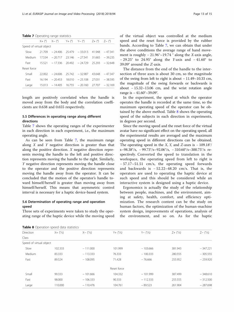
5.5 Differences in operating range along differentdirectionsTable 7 shows the operating ranges of the experimenterin each direction in each experiment, i.e., the maximumoperating angle.As can be seen from Table 7, the maximum range
along X and Y negative direction is greater than thatalong the positive direction. X negative direction repre-sents moving the handle to the left and positive direc-tion represents moving the handle to the right. Similarly,Y negative direction represents moving the handle closeto the operator and the positive direction representsmoving the handle away from the operator. It can beconcluded that the motion of the operator’s handle to-ward himself/herself is greater than moving away fromhimself/herself. This means that asymmetric controlinterval is necessary for a haptic device-based system.
5.6 Determination of operating range and operationspeedThree sets of experiments were taken to study the oper-ating range of the haptic device while the moving speed
of the virtual object was controlled at the mediumspeed and the reset force is provided by the rubberbands. According to Table 7, we can obtain that underthe above conditions the average range of hand move-ment is roughly − 21.96°~19.74 ° along the X-axis angle,− 29.25° to 24.95° along the Y-axis and − 41.60° to39.09° around the Z-axis.The distance from the end of the handle to the inter-
section of three axes is about 30 cm, so the magnitudeof the swing from left to right is about − 11.49~10.33 cm,the magnitude of the swing forwards or backwards isabout − 15.32~13.06 cm, and the wrist rotation anglerange is − 41.60°~39.09°.In the experiment, the speed at which the operator
operates the handle is recorded at the same time, so themaximum operating speed of the operator can be ob-tained by the above method. Table 8 shows the operatingspeed of the subjects in each direction in experiments,in degrees per second.Since the moving speed and the reset force of the virtual
avatar have no significant effect on the operating speed, allthe experimental results are averaged and the maximumoperating speed in different directions can be obtained.The operating speed in the X, Y, and Z-axes is − 109.18°/s~98.38°/s, − 99.73°/s~92.06°/s, − 310.60°/s~300.75°/s re-spectively. Converted the speed to translation in theworkspace, the operating speed from left to right is− 57.17~51.51 cm/s, the operating speed forwardsand backwards is − 52.22~48.20 cm/s. That is, theoperators are used to operating the haptic device atsuch speed and this should be considered while aninteractive system is designed using a haptic device.Ergonomics is actually the study of the relationship
between people, machines, and the environment, aim-ing at safety, health, comfort, and efficiency opti-mization. The research content can be the study onhuman factors, the optimization of the human-machinesystem design, improvements of operations, analysis ofthe environment, and so on. As for the haptic
Table 7 Operating range statistics
X+ (°) X− (°) Y+ (°) Y− (°) Z+ (°) Z− (°)
Speed of virtual object
Slow 21.709 − 24.406 25.479 − 33.013 41.948 − 47.341
Medium 17.534 − 20.717 23.146 − 27.541 31.665 − 39.235
Fast 15.521 − 17.336 20.492 − 24.729 25.293 − 32.648
Reset force
Small 22.002 − 24.606 25.742 − 32.987 43.648 − 47.347
Fast 16.194 − 20.453 18.010 − 25.108 27.031 − 38.595
Large 15.013 − 14.405 16.755 − 20.160 27.707 − 32.169
Table 8 Operation speed data statistics
Direction X+ (°/s) X− (°/s) Y+ (°/s) Y− (°/s) Z+ (°/s) Z− (°/s)
Class
Speed of virtual object
Slow 102.333 − 111.000 101.999 − 103.666 381.943 − 347.221
Medium 83.333 − 113.333 76.333 − 100.333 280.555 − 305.555
Fast 89.524 − 108.095 71.428 − 76.666 255.952 − 259.920
Reset force
Small 99.333 − 101.666 104.332 − 101.999 387.499 − 348.610
Fast 98.000 − 106.333 90.333 − 112.333 255.555 − 312.500
Large 110.000 − 110.476 104.761 − 89.523 261.904 − 287.698
Li et al. EURASIP Journal on Image and Video Processing (2018) 2018:94 Page 13 of 15

interaction system, not only precise measurement andreliable force feedback but also ergonomics research isrequired to adapt to the operator’s physiology andpsychology. Ergonomic experiments and assessmentsare important to choose proper parameters in designinga comfort and efficient haptic device and the inter-action system.
6 ConclusionsIn this study, a 3-DOF haptic device was designed toprovide three DOF force feedback to human operators.VR-based interactive system using the developed devicewas built and ergonomic experiments were conducted.The effective data collected by the force feedback handlesystem was used for statistical analysis. The characteris-tic efficiency and workspace were mainly analyzed. Stat-istical analysis was used to study the influencing factorincluding the guiding force, the reset force, the speed ofthe virtual object, and the arm length. The experimentalresults can provide evidence for how to design andoptimize the haptic device and the haptic interactive sys-tem. Besides the factors explored in this research, hu-man factors such as the human operator’s character,proficiency, perceptual and behavior habits, and themechanical factor such as the shape of the handle andthe size of the haptic device will also influence the hapticinteraction. These factors would be explored further.
AbbreviationsDOF: Degrees of freedom; LSD: Least significant difference; MFC: MicrosoftFoundation Class; OpenGL: Open Graphics Library; VR: Virtual reality
AcknowledgementsThe authors thank the editor and anonymous reviewers for their helpfulcomments and valuable suggestions.
FundingThis paper is supported by the National Key Research and DevelopmentProgram of China (No. 2016YFB1001301), NSFC 61673114 and ShanghaiAerospace Science and Technology Innovation Fund SAST2017-021.
Availability of data and materialsWe can provide the data.
Authors’ contributionsAll authors take part in the discussion of the work described in thispaper. HL organized the research. AS and BL joined in the design of thehaptic device and conducted calibration experiments. BX and HZparticipated in the formulation of main design targets. This writing wasfinished by HL and supervised by AS. All authors approved the finalversion of this paper.
Authors’ informationHui-Jun Li received her B.S. degree in measurement and control in 1999, andM.S. degree in condensed matter physics in 2002 from Zhengzhou University,Zhengzhou, and Ph.D. degree in measurement and control from SoutheastUniversity, Nanjing, in 2005. She is currently an associate professor with theSchool of Instrument Science and Engineering, Southeast University, Nanjing.Her research interests are on teleoperation, space robot, and rehabilitationrobot.Ai-Guo Song received the B.S. degree in automatic control and the M.S. degreein measurement and control from the Nanjing University of Aeronautics andAstronautics, Nanjing, China, in 1990 and 1993, respectively, and the Ph.D.
degree in measurement and control from Southeast University, Nanjing, China,in 1996. From 1996 to 1998, he was an Associate Researcher with the IntelligentInformation Processing Laboratory, Southeast University. From 1998 to 2000, hewas an Associate Professor with the Department of Instrument Science andEngineering, Southeast University. From 2000 to 2003, he was the Director ofthe Robot Sensor and Control Laboratory, Southeast University. From April 2003to April 2004, he was a Visiting Scientist with the Laboratory for IntelligentMechanical Systems, Northwestern University, Evanston, IL, USA. He is currentlya Professor with the School of Instrument Science and Engineering, SoutheastUniversity. His current interests include teleoperation, haptic display, Internettelerobotics, and distributed measurement systems.Bo-Wei Li received her B.S. degree in measurement and control in 2013 fromNanjing University of Science and Technology and M.S. degree in condensedmatter physics from Southeast University, Nanjing, in 2016. She is currentlyan engineer engaging in the development of human-machine interface andrelated algorithms.Bao-Guo Xu received his B.S. degree in measurement and control fromChina University of Mine and Technology, Xuzhou, China, in 2004 and Ph.D.degree in measurement and control from Southeast University, Nanjing, China,in 2009. He is currently an Associate Professor in the School of InstrumentScience and Engineering, Southeast University. His interests include braincomputer interface and rehabilitation robot.Hong Zeng received the Ph.D. degree in computer science from Hong KongBaptist University, Hong Kong, in 2010. He is currently an Associate Professorwith the State Key Laboratory of Bioelectronics, Robot Sensor and ControlLaboratory, School of Instrument Science and Engineering, SoutheastUniversity, Nanjing, China. His current research interests include bioRobot/bioMechatronic interfaces, haptic interaction systems and cortically coupledhuman-machine collaboration.
Ethics approval and consent to participateNot applicable.
Consent for publicationNot applicable.
Competing interestsThe authors declare that they have no competing interests.
Publisher’s NoteSpringer Nature remains neutral with regard to jurisdictional claims inpublished maps and institutional affiliations.
Received: 15 July 2018 Accepted: 6 September 2018
References1. A. Bolopion, S. Régnier, A review of haptic feedback teleoperation systems
for micromanipulation and microassembly[J]. IEEE Trans. Autom. Sci. Eng.10(3), 496–502 (2013)
2. T. Sasaki, K. Kokubo, H. Sakai, Hydraulically driven joint for a force feedbackmanipulator[J]. Precis. Eng. 47, 445–451 (2017)
3. C. Pacchierotti, L. Meli, F. Chinello, et al., Cutaneous haptic feedback toensure the stability of robotic teleoperation systems[J]. Int. J. Robot Res.34(14), 1773–1787 (2015)
4. F. Oscari, R. Oboe, O.A. Daud Albasini, et al., Design and construction of abilateral haptic system for the remote assessment of the stiffness and rangeof motion of the hand[J]. Sensors 16(10), 1633 (2016)
5. Laycock S D, Day A M. Recent developments and applications of hapticdevices[C], Computer Graphics Forum. Oxford: Blackwell Publishing, Inc,2003, 22(2): 117–132.
6. D. Borro, J. Savall, A. Amundarain, et al., A large haptic device for aircraftengine maintainability [J]. IEEE Comput. Graph. Appl. 24(6), 70–74 (2004)
7. R.J. Adams, M.R. Moreyra, B. Hannaford, in Proc of the Asme Winter AnnualMeeting Haptics Symposium. Excalibur, a three-Axis force display[J] (2010)
8. M.C. Çavuşoğlu, D. Feygin, F. Tendick, A critical study of the mechanical andelectrical properties of the phantom haptic interface and improvements forhighperformance control[J]. Presence Teleop. Virt. 11(6), 555–568 (2002)
9. Xitact Medical Simulation, http://www.xitact.com. Accessed 16 Sept 2018.
Li et al. EURASIP Journal on Image and Video Processing (2018) 2018:94 Page 14 of 15
10. M. Noakes, L. Love, P. Lloyd, Telerobotic planning and control for DOE D&Doperations (IEEE International Conference on Robotics and Automation,Washington DC, 2002), pp. 3485–3492
11. E.L. Faulring, J.E. Colgate, M.A. Peshkin, The cobotic hand controller: Design,control and performance of a novel haptic display[J]. Int. J. Robot. Res.25(11), 1099–1119 (2006)
12. X.J. He, K.S. Choi, Safety control for impedance haptic interfaces[J].Multimed. Tools Appl. 75(23), 15795–15819 (2016)
13. Sun X, Andersson K, Sellgren U, Towards a Methodology forMultidisciplinary Design Optimization, Proceedings of the ASME 2015International Design Engineering Technical Conferences & Computers andInformation in Engineering Conference IDETC/CIE 2015, Boston,Massachusetts, USA; 2015.
14. H. Qin, A. Song, Y. Liu, et al., Design and calibration of a new 6 DOF hapticdevice[J]. Sensors 15(12), 31293–31313 (2015)
15. B. Sauvet, T. Laliberte, C. Gosselin, Design, analysis and experimentalvalidation of an ungrounded haptic interface using a piezoelectricactuator[J]. Mechatronics 45, 100–109 (2017)
16. I. Sarakoglou, N. Garcia-Hernandez, N.G. Tsagarakis, et al., A highperformance tactile feedback display and its integration in teleoperation[J].IEEE Trans. Haptics 5(3), 252–263 (2012)
17. X. Sun, U. Sellgren, K. Andersson, Situated design optimization of hapticdevices[J]. Procedia CIRP 50, 293–298 (2016)
18. H.Z. Tan, M.A. Srinivasan, B. Eberman, et al., Human factors for the design offorce-reflecting haptic interfaces[J]. Dyn. Syst. Control 55(1), 353–359 (1994)
19. R. Ellis, O. Ismaeil, M. Lipsett, Design and evaluation of a high-performancehaptic interface. Robotica 14, 321–327 (1996)
20. Yoon W K, Suehiro T, Tsumaki Y, et al. A method for analyzing parallelmechanism stiffness including elastic deformations in the structure[C].Intelligent Robots and Systems, 2002. IEEE/RSJ International Conference on.IEEE, 2002(34):633–634
Li et al. EURASIP Journal on Image and Video Processing (2018) 2018:94 Page 15 of 15