Embed Size (px)
Citation preview
2
CONFIDENTIAL
EXPERT REPORT OF DR. FREDERICK “GENE” BECK
TABLE OF CONTENTS I. Scope Of Review. .............................................................................. 11
II. Executive Summary. .......................................................................... 11
III. Education, Expertise, And Experience. ............................................. 17
IV. Introduction. ....................................................................................... 19
V. BP Failed To Follow Its Own Written Practices And Violated Federal Regulations When Operating The Macondo Well. ................................................................................... 20
A. Pursuant to BP’s written practices and industry practice, BP held and exercised ultimate responsibility for the design, operation, and control of the Macondo well; BP’s ultimate responsibility extended to all operations conducted by or on behalf of BP by contractors. ............................................................................... 20
B. BP’s written practices generally set forth high standards governing BP’s conduct in its drilling operations. Significantly, BP’s written practices prioritize safety first and time to production last. ......................................................................... 21
C. BP repeatedly failed to follow its written practices when operating the Macondo well. In particular, BP prioritized cost and time to production over safety. ............................................................. 22
1. BP violated federal regulations and in doing so also failed to follow DWOP § 2.2.................................................................................... 23
2. BP failed to follow DWOP § 1.2 and DWOP § 2.3 when it failed to maintain high and consistent drilling standards and instead prioritized cost and time to production over safety..................................................... 24

3
CONFIDENTIAL
EXPERT REPORT OF DR. FREDERICK “GENE” BECK
3. BP failed to follow DWOP § 2.4 when it did not establish clear roles and responsibilities for its employees on the Deepwater Horizon. ........................................................ 24
4. BP failed to follow DWOP § 3.3.1 when it did not manage risks to the lowest level possible................................................................... 25
5. BP failed to follow DWOP § 4.4 when it did not follow its formal management of change process. .............................................................. 25
6. BP failed to follow DWOP § 15.2.15 when it did not convert the float collar before entering the open hole. ........................................ 29
7. BP failed to follow DWOP § 26.1.3 when BP did not direct or approve a top of cement design that met BP’s zonal isolation design criteria.................................................... 29
8. BP failed to follow DWOP § 26.2.1 when it did not maintain two temporary barriers at all times.......................................................... 30
9. BP failed to follow DWOP § 26.2.2 when it did not install two independently tested barriers in the Macondo well. .......................................... 30
10. BP failed to follow ETP GP 10-60 §§ 5.3.1 and 5.3.3 when it decided not to run a cement bond log. ................................................... 30
11. BP failed to follow its written practices for cement operations when it decided not to circulate the entire well volume prior to commencing cement operations......................... 31
12. BP failed to follow its zonal isolation criteria in regard to centralizer placement........................................................................ 31
4
CONFIDENTIAL
EXPERT REPORT OF DR. FREDERICK “GENE” BECK
VI. BP Designed A Substandard Well And Prioritized Economics Above Safety................................................................... 31
A. BP failed to provide a safe drilling margin................................ 31
B. BP acted unreasonably when it pumped heavy drilling mud with a high equivalent circulating density into the well without first repairing the damaged formation at the bottom of the well.................................................................................. 37
C. BP was imprudent in choosing to use a long string production casing. .......................................................... 40
1. BP increased the risk of cement contamination by using a long string production casing. ........................................................... 42
2. BP required the application of higher equivalent circulating densities to the fragile formations at the bottom of the well by using a long string production casing. ............................................................................. 44
3. BP failed to provide two independently tested barriers to annular flow by using a long string production casing. ...................................... 45
4. BP went with the riskier long string design for financial reasons. ........................................... 45
D. BP misidentified the uppermost hydrocarbon-bearing zone, and consequently achieved neither proper zonal isolation nor effective management of annular pressure buildup in the Macondo well...................................................................... 48
1. BP misidentified the uppermost hydrocarbon-bearing zone. ............................................. 48
2. Because BP misidentified the uppermost hydrocarbon-bearing zone,

5
CONFIDENTIAL
EXPERT REPORT OF DR. FREDERICK “GENE” BECK
BP failed to follow both its own guidelines and violated a federal regulation concerning zonal isolation.............................. 50
3. Because BP misidentified the uppermost hydrocarbon-bearing zone, BP failed to effectively manage annular pressure buildup.............................................................. 51
E. BP imprudently elected not to use a float shoe to provide an additional barrier in the shoe track. ......................................................................................... 52
VII. BP Failed To Prudently Manage Operations And Made Several Decisions That Caused The Blowout. ........................ 54
A. BP drilled an unstable wellbore. ............................................... 54
B. BP acted unreasonably when it decided to use only six centralizers despite Halliburton’s recommendation of at least twenty-one centralizers. .............................................................................. 54
C. BP chose not to convert the auto-fill float collar at the safest position in the wellbore. ............................. 61
D. BP likely damaged the float collar. ........................................... 62
1. BP used brute force and high pressures in its failed attempt to convert the float collar, disregarding the manufacturer’s warning of potential consequences. ............................... 68
2. BP ignored that it likely damaged the float collar with the high pressures it applied. ............................................................................ 74
E. BP created wellbore conditions that were conducive to plugging and damaging the casing, float collar, and/or shoe track....................................... 75
6
CONFIDENTIAL
EXPERT REPORT OF DR. FREDERICK “GENE” BECK
1. Transocean confirmed Weatherford’s warning about ejecting the float collar ball. .................................................................................. 75
2. Transocean confirmed that an undamaged, properly converted float collar would have prevented flow up the shoe track by way of its pair of valves at the top of the shoe track.................................................. 77
F. BP could have avoided the consequences of its failure to convert the float collar without damaging it. Instead, BP’s failure to convert the float collar at the safest time, and subsequent failure to repair the damaged float collar, led to the blowout........................................................... 77
G. BP unreasonably chose not to circulate bottoms up or to adequately condition the wellbore for cement placement. ............................................... 78
H. BP unreasonably failed to confirm the function of the check valves in the float collar. ...................................... 79
I. BP jeopardized the shoe track cement’s ability to form a barrier to hydrocarbon flow. ...................................... 80
1. BP indicated it was pleased with Halliburton’s cement work. .............................................. 80
2. BP provided inadequate centralization and allocated insufficient time for waiting-on-cement, thereby jeopardizing the cement job................................................................. 81
3. Halliburton did not cause any failure of the shoe track cement job. .............................................. 82
J. BP unreasonably canceled the cement bond log previously scheduled with Schlumberger to evaluate the upper annular cement placement. ................................................................................ 88

7
CONFIDENTIAL
EXPERT REPORT OF DR. FREDERICK “GENE” BECK
K. BP failed to provide a safe temporary abandonment plan.................................................................... 89
1. BP took unnecessary risks by planning to set the lockdown sleeve last. ...................................... 91
2. BP’s plan did not provide for two independently tested barriers along each of the potential flow paths. ..................................... 92
3. BP risked damaging the shoe track cement by performing the positive and negative pressure tests shortly after pumping the cement........................................................ 95
L. In performing the negative pressure test, BP and Transocean recklessly attributed the increase in pressure on the drill pipe to the so-called “bladder effect.” .............................................................. 95
M. BP and MI-SWACO used inappropriate lost circulation material as a spacer to avoid environmental regulations, which likely clogged the kill line and led to BP’s disregard of the negative pressure test results. ....................................... 99
N. BP recklessly caused the blowout when it proceeded with the displacement to seawater following the clear and undeniable indication from the negative pressure test that well integrity had not been established. ........................................ 103
O. Sperry acted reasonably while monitoring the final displacement................................................................... 103
1. Transocean had primary well monitoring responsibility during operations; Sperry provided only a second set of eyes on the well. ......................................................................... 105
2. BP and Transocean conducted simultaneous and non-standard
8
CONFIDENTIAL
EXPERT REPORT OF DR. FREDERICK “GENE” BECK
operations that obscured primary kick indicators during the final displacement........................ 109
a) BP and Transocean prevented Sperry from observing any pit volume gain.......................................................... 111
b) Sperry acted reasonably in checking for well flow........................................... 112
c) BP and Transocean failed to identify an increase in flow following the sheen test. ...................................... 113
d) BP and Transocean prevented Sperry from monitoring gas concentration. ...................................................... 114
e) Detection of pressure anomalies was complicated by the lack of a predicted pressure/volume schedule............................................................... 115
f) A reasonable mudlogger would not have focused on hookload as a kick indicator. .................................................... 116
3. While not available in real time, post-incident analysis suggests there was little to no well flow before diverting overboard. ..................................................................... 116
a) Sperry’s mudlogger acted reasonably under the circumstances. ..................................................... 117
VIII. Summary Of Key Findings............................................................... 118

9
CONFIDENTIAL
EXPERT REPORT OF DR. FREDERICK “GENE” BECK
LIST OF FIGURES
Figure 1: Narrow Drilling Margins (Redrawn from Figure 4.2.2, Chief Counsel’s Report)
Revised Figure 2: Narrow Drilling Margin Remedy Figure 3: Alternate Liner Design Figure 4: Casing Options in Deepwater Drilling Figure 5: Detail of Liner Design
Figure 6: Mechanical Barriers to Flow Figure 7: Channeling Revised Figure 8: Gagliano’s Recommendation: Normal Centralizer Placement
and Parameters Revised Figure 9: BP’s Actual Placement: Lack of Centralizers May Result in Low
Stand-off Ratio Figure 10: U-Tubing Figure 11: Weatherford M45AP Float Collar Used In Macondo Well Figure 12: Flow-Activated Auto-Fill Float Collar Figure 13: Obstructions Prevent Circulation Figure 14: Nine Attempts Prior to Assumed Conversion of Float Collar on
April 19, 2010 (Figure 13 from Transocean Report, Alteration Added)
Figure 15: Failure to Convert the Float Collar

10
CONFIDENTIAL
EXPERT REPORT OF DR. FREDERICK “GENE” BECK
Figure 16: Shoe Track Blowout Figure 17: Shoe Track Cement Contamination Figure 18: Overview of Events during the Negative Pressure Test from
5:34-8:02 p.m. (Partial Reproduction of Figure 20 from Transocean Report)
Figure 19: The Negative Pressure Test

11
CONFIDENTIAL
EXPERT REPORT OF DR. FREDERICK “GENE” BECK
I. Scope Of Review.
At the request of United States Senator Jeff Bingaman, I previously testified before the United States Senate regarding well design and control protection techniques relevant to the April 20, 2010 blowout of the Macondo well. More recently, at the request of counsel for Halliburton Energy Services, Inc., I have studied the Macondo blowout with respect to well design, control, drilling, and monitoring. I have investigated the blowout from the standpoint of a petroleum engineer using my expertise both as a petroleum engineer and as a drilling operations manager with extensive experience in well design and drilling operations.
II. Executive Summary.
BP, the majority owner and operator of the Macondo well, was responsible for all aspects of the design, development, and operation of the well from initiation to completion. Based on my analysis of the evidence, it is my conclusion that BP caused the blowout by recklessly losing control of the well when it decided to significantly underbalance the well even though its preceding negative pressure test demonstrated an influx of high-pressure hydrocarbons flowing into the well. Despite the negative pressure test results, BP went ahead and opened the blowout preventer (BOP) to the riser and displaced the heavy balancing mud in the riser (and much of the well) with much lighter seawater, thus significantly underbalancing the well and allowing hydrocarbon gases to rush up the well and riser to the rig, flooding the rig with explosive gas. These actions were part of a pattern of conduct whereby BP repeatedly ignored accepted good drilling practices, federal regulations, and its own internal guidelines that required safety to be prioritized ahead of cost and time to production. It is also my conclusion that the blowout was caused, to a lesser extent, by the conduct of BP’s contractor Transocean.
To start, BP dictated an unreasonably risky well design in several respects to save time and money. For example:
BP created a very narrow drilling margin by failing to reinforce fragile sections of the well;
BP ignored and failed to disclose the existence and location of the uppermost hydrocarbon-bearing zone (the M57B zone), which

12
CONFIDENTIAL
EXPERT REPORT OF DR. FREDERICK “GENE” BECK
otherwise would have required BP to redesign the well to comply with federal regulations and BP’s own guidelines;
BP used a long string production casing instead of a liner to save approximately $7-10 million, increasing the likelihood that the fragile Macondo well would leak;
BP ignored Halliburton’s advice that at least 21 centralizers were needed to achieve zonal isolation and avoid channeling — instead BP used only 6 centralizers;
BP ignored Halliburton’s warning, based on its industry-recognized OptiCem™ software, that BP’s well design presented a SEVERE gas flow potential;
BP dictated a shoe track design that included only an upper barrier at the float collar with one set of valves, as opposed to the more prudent practice of also including a lower barrier by way of a float shoe with another set of valves; and
BP failed to perform even a single bottoms up circulation to clean the wellbore from debris and gelled mud prior to cementing, increasing the risk of cement contamination, channeling, and lost circulation (BP and Halliburton recommend two bottoms up circulations).
BP also dictated an unreasonably risky temporary abandonment procedure for the Macondo well. It repeatedly changed its temporary abandonment procedure and, after switching back-and-forth at the last minute, arrived at an unorthodox procedure intended to save time and money, albeit at the expense of safety. For example:
BP inappropriately used leftover lost circulation material as a spacer in advance of its displacement to seawater (BP would otherwise have needed to process the lost circulation material onshore as hazardous waste);
BP implemented the steps of its temporary abandonment procedure out of the ordinary sequence by not setting the lockdown sleeve first and instead planning to do so last, after displacing the heavy mud in the riser (and a substantial portion of the well) with much lighter seawater, and not setting a second, upper cement plug prior to
13
CONFIDENTIAL
EXPERT REPORT OF DR. FREDERICK “GENE” BECK
displacing the riser and well to seawater, thus substantially underbalancing the well;
BP failed to obtain a cement bond log to inspect the top of cement in the annulus, instead choosing to send home the Schlumberger cement bond log crew that already was available on board the Deepwater Horizon; and
BP permitted simultaneous and non-standard operations during the final Macondo displacement that unnecessarily complicated detection of kick indicators.
All of the foregoing decisions rendered the Macondo well a high-risk and dangerous well that was described by BP’s own engineers as a “nightmare.”1
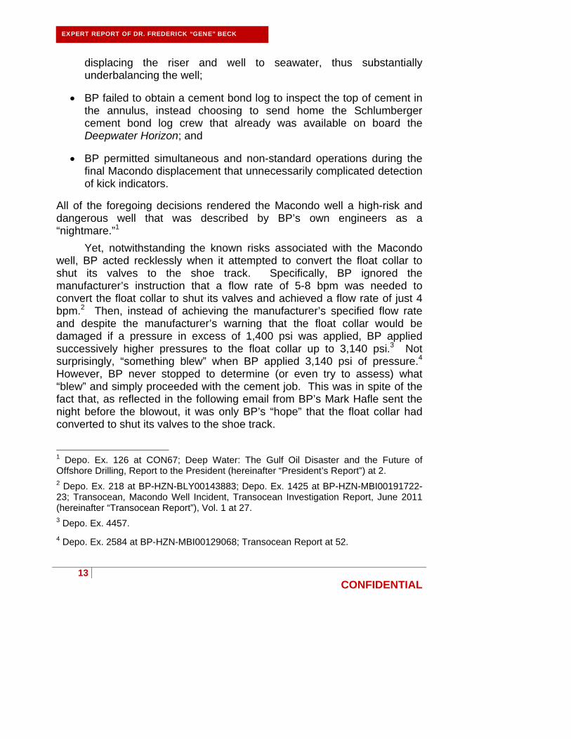
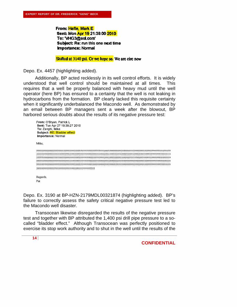
Yet, notwithstanding the known risks associated with the Macondo well, BP acted recklessly when it attempted to convert the float collar to shut its valves to the shoe track. Specifically, BP ignored the manufacturer’s instruction that a flow rate of 5-8 bpm was needed to convert the float collar to shut its valves and achieved a flow rate of just 4 bpm.2 Then, instead of achieving the manufacturer’s specified flow rate and despite the manufacturer’s warning that the float collar would be damaged if a pressure in excess of 1,400 psi was applied, BP applied successively higher pressures to the float collar up to 3,140 psi.3 Not surprisingly, “something blew” when BP applied 3,140 psi of pressure.4
However, BP never stopped to determine (or even try to assess) what “blew” and simply proceeded with the cement job. This was in spite of the fact that, as reflected in the following email from BP’s Mark Hafle sent the night before the blowout, it was only BP’s “hope” that the float collar had converted to shut its valves to the shoe track.
1 Depo. Ex. 126 at CON67; Deep Water: The Gulf Oil Disaster and the Future of Offshore Drilling, Report to the President (hereinafter “President’s Report”) at 2. 2 Depo. Ex. 218 at BP-HZN-BLY00143883; Depo. Ex. 1425 at BP-HZN-MBI00191722-23; Transocean, Macondo Well Incident, Transocean Investigation Report, June 2011 (hereinafter “Transocean Report”), Vol. 1 at 27. 3 Depo. Ex. 4457.
4 Depo. Ex. 2584 at BP-HZN-MBI00129068; Transocean Report at 52.
14
CONFIDENTIAL
EXPERT REPORT OF DR. FREDERICK “GENE” BECK
Depo. Ex. 4457 (highlighting added).
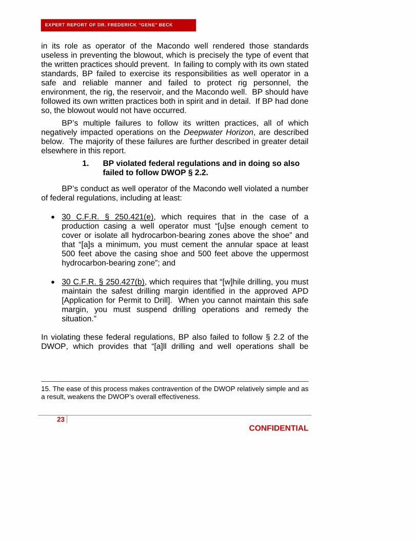
Additionally, BP acted recklessly in its well control efforts. It is widely understood that well control should be maintained at all times. This requires that a well be properly balanced with heavy mud until the well operator (here BP) has ensured to a certainty that the well is not leaking in hydrocarbons from the formation. BP clearly lacked this requisite certainty when it significantly underbalanced the Macondo well. As demonstrated by an email between BP managers sent a week after the blowout, BP harbored serious doubts about the results of its negative pressure test:
Depo. Ex. 3190 at BP-HZN-2179MDL00321874 (highlighting added). BP’s failure to correctly assess the safety critical negative pressure test led to the Macondo well disaster.
Transocean likewise disregarded the results of the negative pressure test and together with BP attributed the 1,400 psi drill pipe pressure to a so-called “bladder effect.” Although Transocean was perfectly positioned to exercise its stop work authority and to shut in the well until the results of the

15
CONFIDENTIAL
EXPERT REPORT OF DR. FREDERICK “GENE” BECK
negative pressure test were fully explored, it instead encouraged accepting the test results as satisfactory. As is the case with BP, Transocean’s failure to correctly assess the safety critical negative pressure test led to the Macondo well disaster.
Additionally, after missing prior kicks in the Macondo well, BP and Transocean similarly failed to detect the kick that started the disastrous blowout. Considering that it was engaged in a sensitive displacement on a difficult well involving an unnecessarily large volume of lost circulation material spacer that had never before been used or tested, BP should have provided its contractors with a pressure and volume schedule to aid in the detection of well anomalies. BP instead did not provide a schedule and further complicated the displacement with abnormal simultaneous operations. For its part, Transocean failed to act as a prudent drilling contractor during the critical circulation phase of the temporary abandonment procedure by constantly transferring fluids between tanks, confounding pit monitoring. A prudent contractor would have paid more attention to the well and would have avoided the unnecessary fluid transfers and other non-standard operations that masked the ultimate kick.
Transocean is also complicit in the blowout of the Macondo well because it failed to control the well after hydrocarbons flowed into the long string production casing following the failed negative pressure test. Transocean, as employer of the drilling crew and owner of Deepwater Horizon, was responsible for monitoring the well during drilling operations. Transocean failed to act as a prudent drilling contractor during the critical circulation phase of the temporary abandonment procedure during which several simultaneous operations were taking place.
The blowout and resulting tragic deaths and oil spill were reasonably foreseeable risks of BP’s reckless failure to maintain control of the Macondo well. On the other hand, BP’s recklessness in losing control of the well—by damaging the float collar with excessively high pressures and by ignoring clear indicators that the negative pressure test failed—was not reasonably foreseeable to the contractors like Sperry and Halliburton. Neither Sperry nor Halliburton received or were responsible for collecting information sufficient to be aware of BP’s recklessness. Contractors reasonably expect the well operator, in this case BP, to maintain well control at all times.
Other parties have suggested that Sperry may be partially to blame for the failure to detect the final kick that resulted in the blowout. I

16
CONFIDENTIAL
EXPERT REPORT OF DR. FREDERICK “GENE” BECK
disagree. Sperry provides a second set of eyes when acting as mudloggers on a well. Transocean, not Sperry, held primary responsibility for monitoring the well during operations. Sperry’s ability to act as the secondary well monitor was compromised by the simultaneous and non-standard displacement operations conducted by BP and Transocean. These simultaneous operations obscured the Sperry mudlogger’s vision of fluid volume from the well, which is the mudlogger’s primary kick detection tool. By diverting the lost circulation material overboard, Transocean bypassed the only flow and gas detection sensors available to Sperry, rendering the Sperry mudlogger blind to all flow out of the well. BP and Transocean, in contrast, continued to see flow-out during this time because they had access to Transocean’s flow sensor data, which Sperry did not have despite Sperry’s request for that data. It is my conclusion that Transocean and BP are responsible for failing to detect the kick. They were the only parties with access to all operational and kick detection information, including Transocean’s own monitoring sensors, and Transocean had primary responsibility for kick detection.
It should be noted that the rapidity with which the blowout occurred offered little opportunity for crews to assess and respond to the changing well conditions. As the owner and operator, BP was the only party fully aware of the flow potential of the subsurface hydrocarbon bearing formations. BP should have been extremely cautious and diligent in assuring that the hydrocarbons were not allowed to flow freely into the wellbore, knowing that well control could be lost in an instant. BP failed to ensure that the well was adequately monitored during the critical displacement to seawater.
Other parties have suggested that Halliburton’s cement mixture may have been bad, to the point that it caused the primary cement job to fail to achieve zonal isolation. I disagree because the evidence establishes other likely failures of zonal isolation, including:
channeling and cement contamination caused by BP’s risky well design, including inadequate centralization, the use of a long string production casing, the absence of any bottoms up circulation to clean the well prior to pumping in the cement, and the failure to guard against rathole swapping;
movement of the cement (u-tubing) through the float collar that BP damaged and failed to convert (leaving its valves wide open) and subsequent variable wellbore pressures caused by ongoing rig

17
CONFIDENTIAL
EXPERT REPORT OF DR. FREDERICK “GENE” BECK
operations, when instead the well should have been left undisturbed to allow the cement to cure;
damage to the shoe track caused by the high pressures applied by BP in BP’s repeated failed attempts to convert the float collar to shut its valves to the shoe track; and/or
BP’s failure to wait 24-48 hours to ensure that the cement had adequately set.
It is also important to note that a failed primary cement job, whatever
the cause, does not equate to a blowout. A blowout is not a reasonably foreseeable result of a failed primary cement job. Rather, when a primary cement job fails to provide zonal isolation, as should be detected in performing the negative pressure test and/or the cement bond log test, the foreseeable result is that the primary cement job has to be corrected by adding more cement through a process known as remedial cementing (remediation), e.g., by performing a “squeeze job” in which the casing adjacent to the leaky zone is perforated and cement is pumped through the perforations. Again, the foreseeable result of a failed primary cement job is not a blowout. The foreseeable result of a failed primary cement job is a cement repair job and the time and money necessarily incurred in performing the cement repair job.
Accordingly, it is my finding that Halliburton and Sperry did not in any way cause, and are not responsible for, the blowout. It is also my finding that BP’s reckless failure to maintain control of the well, and to a lesser extent Transocean’s conduct, caused the blowout, the tragic loss of eleven lives, and the oil spill.
III. Education, Expertise, And Experience.
I have thirty years of experience in the oil and gas industry. I am an Associate Professor and Stephen A. Holditch Faculty Fellow in the Department of Petroleum Engineering at Texas A&M University in College Station, Texas. I am also a drilling consultant for a small publicly traded oil and gas company.
I received my B.S. degree in geology from the Louisiana State University in 1981. I subsequently received both a M.S. degree and Ph.D. degree in petroleum engineering from the Louisiana State University in 1984 and 1986, respectively. After receiving my Ph.D. in 1986 I joined the New Mexico School of Mines as an assistant professor and simultaneously

18
CONFIDENTIAL
EXPERT REPORT OF DR. FREDERICK “GENE” BECK
served as a consultant to ARCO Oil and Gas. I left academia and took a full time position with ARCO Alaska, Inc. as a drilling engineer and rig supervisor in 1990. While at ARCO Alaska, my responsibilities included the planning and supervision of rig operations. I served in the role of lead engineer for numerous wells in the Prudhoe Bay Unit, designing and supervising the first short radius horizontal well in Prudhoe Bay. In these capacities, I developed extensive field supervisory experience with respect to drilling, completions, and workovers.
I left ARCO Alaska in 1996 to work as a consultant for Nabors Alaska Drilling, Inc., and eventually became Vice President at Nabors Drilling USA, Inc. I also began teaching industry short courses, initially through Murchison Drilling Schools and later at the Chevron Drilling Training Alliance. While at Nabors, my responsibilities included the management of turnkey drilling operations, the development and implementation of company-wide well control and drilling policies, the negotiation and management of third-party contracts, and the management of subcontractor relationships. I also acted as an in-house consultant for well control and safety related incidents on Nabors’ rigs. Through my work at Nabors, I became adept at drilling the difficult high-pressure wells along the Louisiana and Texas Gulf Coasts.
I left Nabors in 2002 and went to work as both a consultant and as the Vice President of Drilling and Operations for Gastar Exploration, Ltd. As a consultant, I served as an expert witness and continued to teach short courses at the Chevron training center. I took my current position at Texas A&M in 2009.
I have been recognized as a Distinguished Lecturer by the Society of Petroleum Engineers (SPE) and have been a member of several committees for petroleum-related organizations, including the International Association of Drilling Contractors. I have participated in SPE committees, including the Drilling Program Committee for the SPE Annual Technical Conference and Exhibition and the SPE High Pressure High Temperature Operations committee. I have authored several publications related to drilling, well control, and completions.
I received Exceptional Contribution awards from ARCO for my work in Prudhoe Bay. I was the recipient of the Texas A&M Petroleum Engineering Department award for Excellence in Teaching in both 2010 and 2011.

19
CONFIDENTIAL
EXPERT REPORT OF DR. FREDERICK “GENE” BECK
In sum, I have been actively involved in drilling engineering, well site supervision, and operations management in the oil and gas industry for over 20 years, and have been involved on an academic basis for 30 years. My industry experience is current and I continue to be actively involved in well planning and operations management in addition to my academic pursuits. I have successfully designed and drilled numerous high pressure/high temperature gas wells to depths in excess of 20,000 feet and am fully competent and capable of providing engineering and operations-based insight into the events leading to the blowout of the Macondo well.
My current curriculum vitae, which includes a list of my publications that I have authored in the past ten years and a list of all other cases in which I have provided testimony during the past four years, is attached as Appendix A. I am being compensated at the rate of $500 per hour for my time spent testifying and at a rate of $400 per hour my time spent on all other tasks performed in my role as an expert witness in this matter. The materials that I have considered in preparing this report are listed in Appendix B.
IV. Introduction.
On April 20, 2010, an explosion and fire occurred on the Deepwater Horizon, a semi-submersible drilling rig owned by Transocean and under contract to BP. At that time, the Deepwater Horizon was engaged in completing BP’s Macondo prospect in the Mississippi Canyon of the Gulf of Mexico. Eleven men lost their lives, the drilling vessel was lost at sea, and an out of control subsea well spewed oil and natural gas into the Gulf of Mexico, resulting in an environmental disaster.
BP operated the Macondo well on behalf of itself and its partners. As well operator, BP held ultimate responsibility for all aspects of well design and execution, employing various contractors and service companies at its discretion and under its control to assist it in drilling the well. Drilling a well such as the Macondo is a massive undertaking, made even more difficult in that the Macondo prospect was an exploration well.
Exploration well drilling is risky by nature, as information pertinent and critical to operational success is rarely known to a great degree of certainty. Design and execution decisions are not always straightforward and must be made with risk management in mind at all times. Because of this inherent uncertainty, design and execution decisions made with even the best of intentions can meet with less than desirable results. Well

20
CONFIDENTIAL
EXPERT REPORT OF DR. FREDERICK “GENE” BECK
operators like BP must understand this reality and accept that unexpected events or conditions often require well-related goals and objectives to be sacrificed in favor of conducting safe operations. In any drilling operation safety must be given first priority, and it has been my experience that when safety is sacrificed for economic gain the consequences can be dire.
Safe and successful drilling operations require safety critical tests to be conducted and assessed at various stages throughout the design, construction, and operation of a well, with each test providing a critical opportunity to repair flaws in the design or execution process. Here, BP’s and Transocean’s failure to correctly assess the safety critical negative pressure test led to the Macondo well disaster.
V. BP Failed To Follow Its Own Written Practices And Violated Federal Regulations When Operating The Macondo Well.
A. Pursuant to BP’s written practices and industry practice, BP held and exercised ultimate responsibility for the design, operation, and control of the Macondo well; BP’s ultimate responsibility extended to all operations conducted by or on behalf of BP by contractors.
In an attempt to ensure that all of its drilling operations are conducted in a safe and responsible manner that is consistent with all relevant laws and regulations, BP put in place its Operating Management System (OMS).5 Key components of the OMS are the Drilling and Well Operations Practice (DWOP) and Engineering Technical Practices (ETPs).6 Together, the DWOP and associated ETPs provide a written framework for designing and conducting drilling operations.7
BP’s written practices make clear that BP intends to maintain total control of all aspects of well design and drilling operations. This is consistent with BP’s role as well operator. At all times, the well operator has the ultimate responsibility to assure that a well is drilled safely. The well operator takes ownership of any procedure, device, process, or decision used in the course of conducting drilling operations. It is the sole
5 Depo. Ex. 6121 at BP-HZN-BLY00034512 (DWOP § 1.2). 6 Depo. Ex. 6121 at BP-HZN-BLY00034512 (DWOP § 1.2). 7 Depo. Ex. 6121 at BP-HZN-BLY00034512 (DWOP § 1.2).

21
CONFIDENTIAL
EXPERT REPORT OF DR. FREDERICK “GENE” BECK
responsibility of the well operator to ensure that all operations, procedures, and materials used during the course of drilling a well meet or exceed standards required for safe operations.
All operations that are conducted for or on behalf of the well operator are owned by the well operator. On the Deepwater Horizon, operations conducted for or on behalf of BP, and therefore owned by BP, included the operations of BP contractors Transocean, M-I SWACO, Schlumberger, Weatherford, Tidewater Marine, Halliburton, and Sperry.
B. BP’s written practices generally set forth high standards governing BP’s conduct in its drilling operations. Significantly, BP’s written practices prioritize safety first and time to production last.
BP’s DWOP reflects a high bar governing BP’s conduct in its drilling operations. The DWOP recognizes many of the industry standard “Good Drilling Practices” and dictates that BP wells should be “designed, drilled, and completed to high and consistent standards” and in compliance “with all relevant laws and regulations.”8 In regard to risk management, the DWOP states that all risks should “be managed to a level which is as low as reasonably practical.”9
Significantly, the DWOP states that when planning and undertaking drilling and well operations, safety concerns should be prioritized “in order of importance” as Personnel, Environment, The Installation, Reservoir Integrity, and Well Delivery.10 Thus, BP’s written practices state that safety (personnel, environment) should be prioritized first and time to production (well delivery) should be prioritized last.
The DWOP states that that “[c]lear roles, responsibilities, and accountabilities shall be established for all positions within the drilling and well operations organizations,”11 and that “[a]ll staff and contract personnel involved in the management and supervision of drilling and well operations” should be “knowledgeable of the DWOP and associated ETPs.”12 In 8 Depo. Ex. 6121 at BP-HZN-BLY00034512 (DWOP § 1.2). 9 Depo. Ex. 6121 at BP-HZN-BLY00034519 (DWOP § 3.3.1). 10 Depo. Ex. 6121 at BP-HZN-BLY00034516 (DWOP § 2.3). 11 Depo. Ex. 6121 at BP-HZN-BLY00034516 (DWOP § 2.4). 12 Depo. Ex. 6121 at BP-HZN-BLY00034517 (DWOP § 3.1.1).

22
CONFIDENTIAL
addition, the DWOP states that company representatives should be “accountable for the execution of the approved drilling and well operations programmes,”13 that the company representative should “be satisfied that the rig, equipment, and site are in a safe operating condition, and that personnel are trained and competent, prior to commencing drilling and well operations,”14 and that they should “directly observe” specific critical operations.15
The DWOP also addresses several specific concerns, serving as a collective memory of past operational mistakes and cures. For instance, the statement that “[a]uto fill float equipment shall be tripped prior to running through any hydrocarbon bearing zone” recognizes the risks associated with using auto-fill float equipment. 16
Taken as a whole, BP’s written practices set forth high standards that BP should follow in conducting its drilling operations and provide a suitable framework for designing and conducting drilling operations. Several good practices and potential pitfalls are recognized and stated clearly throughout the document. However, the document does suffer from occasional lapses, as in its requirement that “[a]t least one contingent barrier i.e. downhole float valve shall be included on any casing string run through a hydrocarbon bearing zone.”17 This statement is remarkable in that the “gold standard” in the drilling industry is to run both a float collar and a float shoe, creating clear redundancy in the shoe track.
C. BP repeatedly failed to follow its written practices when operating the Macondo well. In particular, BP prioritized cost and time to production over safety.
Obviously, BP’s written practices are only effective if the practices are followed.18 BP’s frequent and repeated contravention of its own standards 13 Depo. Ex. 6121 at BP-HZN-BLY00034517 (DWOP § 3.1.6). 14 Depo. Ex. 6121 at BP-HZN-BLY00034524 (DWOP § 6.2). 15 Depo. Ex. 6121 at BP-HZN-BLY00034544 (DWOP § 15.2.4). 16 Depo. Ex. 6121 at BP-HZN-BLY00034545 (DWOP § 15.2.15). 17 Depo. Ex. 6121 at BP-HZN-BLY00034545 (DWOP § 15.2.13). 18 Section 1.7 of the DWOP addresses this issue by stating that “[d]eviations from the Drilling and Wells Operations Practice and ETPs shall only be considered in exceptional circumstances.” But the section then provides a relatively easy process for requesting a deviation from recognized good practices. Depo. Ex. 6121 at BP-HZN-BLY00034514-
EXPERT REPORT OF DR. FREDERICK “GENE” BECK
23
CONFIDENTIAL
EXPERT REPORT OF DR. FREDERICK “GENE” BECK
in its role as operator of the Macondo well rendered those standards useless in preventing the blowout, which is precisely the type of event that the written practices should prevent. In failing to comply with its own stated standards, BP failed to exercise its responsibilities as well operator in a safe and reliable manner and failed to protect rig personnel, the environment, the rig, the reservoir, and the Macondo well. BP should have followed its own written practices both in spirit and in detail. If BP had done so, the blowout would not have occurred.
BP’s multiple failures to follow its written practices, all of which negatively impacted operations on the Deepwater Horizon, are described below. The majority of these failures are further described in greater detail elsewhere in this report.
1. BP violated federal regulations and in doing so also failed to follow DWOP § 2.2.
BP’s conduct as well operator of the Macondo well violated a number of federal regulations, including at least:
30 C.F.R. § 250.421(e), which requires that in the case of a production casing a well operator must “[u]se enough cement to cover or isolate all hydrocarbon-bearing zones above the shoe” and that “[a]s a minimum, you must cement the annular space at least 500 feet above the casing shoe and 500 feet above the uppermost hydrocarbon-bearing zone”; and
30 C.F.R. § 250.427(b), which requires that “[w]hile drilling, you must
maintain the safest drilling margin identified in the approved APD [Application for Permit to Drill]. When you cannot maintain this safe margin, you must suspend drilling operations and remedy the situation.”
In violating these federal regulations, BP also failed to follow § 2.2 of the DWOP, which provides that “[a]ll drilling and well operations shall be
15. The ease of this process makes contravention of the DWOP relatively simple and as a result, weakens the DWOP’s overall effectiveness.

24
CONFIDENTIAL
planned and performed in compliance with all applicable legislation and regulations.”19
2. BP failed to follow DWOP § 1.2 and DWOP § 2.3 when it failed to maintain high and consistent drilling standards and instead prioritized cost and time to production over safety.
Section 1.2 of the DWOP provides that “BP is committed to conducting its business in a manner which ensures that wells are designed, drilled, completed and maintained to high and consistent standards.”20 Section 2.3 of the DWOP provides that BP’s “[p]riorities for safety when planning and undertaking drilling and well operations shall be, in order of importance: 1. Personnel. 2. Environment. 3. The installation. 4. Reservoir integrity. 5. Well delivery.”21 These statements establish the “spirit” of BP’s DWOP and associated ETPs and mandate that BP employees should work to high standards. In the interest of saving time and money, BP chose not to honor these stated directives at the Macondo well, particularly the directive that safety of persons and the protection of the environment be prioritized over well delivery and physical assets.
3. BP failed to follow DWOP § 2.4 when it did not establish clear roles and responsibilities for its employees on the Deepwater Horizon.
Section 2.4 of the DWOP provides that “[c]lear roles, responsibilities and accountabilities shall be established for all positions within the drilling and well operations organisations.” It is clear that BP’s April 2010 reorganization created much disorganization and conflict relating to the roles and responsibilities of certain individuals with responsibility for the Macondo drilling operations. BP employees who demonstrated frustration or concern regarding these organizational challenges included at least John Guide, David Sims, Brett Cocales, Gregg Walz, Jonathan Sprague, and Pat O’Bryan.22 BP’s failure to establish clear responsibilities and 19 Depo. Ex. 6121 at BP-HZN-BLY00034516 (DWOP § 2.2). 20 Depo. Ex. 6121 at BP-HZN-BLY00034512 (DWOP § 1.2). 21 Depo. Ex. 6121 at BP-HZN-BLY00034516 (DWOP § 2.3). 22 The Bureau of Ocean Energy Management, Regulation and Enforcement—Report Regarding the Causes of the April 20, 2010 Macondo Well Blowout, 9/14/2011
EXPERT REPORT OF DR. FREDERICK “GENE” BECK
25
CONFIDENTIAL
EXPERT REPORT OF DR. FREDERICK “GENE” BECK
accountabilities for its employees on the Deepwater Horizon was apparent when, for example, no one team member had clear responsibility for interpreting the results of BP’s negative pressure test on the Macondo well.23
4. BP failed to follow DWOP § 3.3.1 when it did not manage risks to the lowest level possible.
Section 3.3.1 of the DWOP states that “[a]ll risks shall be managed to a level as low as reasonably practical.” Rather than investing in safer alternatives, BP engaged in a number of unreasonably risky practices in connection with its design, operation, testing, and attempted control of the Macondo well. In just one example, BP chose to install the production casing in a “long string” configuration instead of a liner configuration, which was the much safer and lower risk option. Other failures by BP to manage risks to the lowest level possible are discussed throughout this report.
5. BP failed to follow DWOP § 4.4 when it did not follow its formal management of change process.
Section 4.4 of the DWOP provides that “[a]ny significant changes to a well programme shall be documented and approved via a formal management of change (MOC) process.”24 The management of change process sets forth BP’s “minimum guidelines for the systematic approach to be used for change control and management within the Gulf of Mexico (GoM) Drilling and Completion (D&C) Organization.”25 The management of change process should serve as a disciplined decision making process by incorporating risk analysis, mitigation plan, peer review, and approval requirement and should “be applied consistently for all engineering/planning, process, and operations in the GoM D&C (hereinafter “JIT Report”) at 79-83 (citing, e.g., BP-HZN-MBI00265306; BP-HNZ-MBI002543828); see also evidence cited at JIT Report at 79-83, e.g., BP-HZN-BLY00061325; Tr. of USCG/MMS Investigation (J. Sprague testimony), 12/8/2010, PM Session at 246:2-17; BP-HZN-MBI00222521; Tr. of USCG/MMS Investigation (B. Cocales testimony), 8/27/10 at 271:1-272:16; BP-HZN-MBI00222540; BP-HZN-MBI00254858. 23 L. Lambert Depo., 5/9/2011 at 185:7-8 (“I’m not aware of any one person who declares the test is successful.”). 24 Depo. Ex. 6121 at BP-HZN-BLY00034521. 25 Depo. Ex. 6291 at BP-HZN-2179MDL00339802.

26
CONFIDENTIAL
EXPERT REPORT OF DR. FREDERICK “GENE” BECK
organization.”26 The management of change process, as written, requires: (1) a risk assessment conducted by all affected by the change; (2) a work plan that included details regarding control measures to be implemented for equipment, facilities, process, operations, maintenance, inspection, training, personnel, communication, and documentation; and (3) authorization of the work plan by responsible person or persons.27
In an effort to save time and money, BP frequently failed to follow DWOP § 4.4 while performing drilling operations for the Macondo well. According to the Chief Counsel’s Report, despite the multiple changes made to BP’s plans for the Macondo well after drilling resumed in February 2010, BP followed the management of change process just three times.28 Instead, BP made various “last minute changes,” later described by BP’s John Guide as “flying by the seat of our pants,”29 without using the management of change process at all. Some of BP’s changes made without using the management of change process are:
BP’s decision to have flown to the rig additional centralizers but leave them unused;30
BP’s decision to not to follow a BP written practice by its ad hoc placement of the centralizers;31
26 Depo. Ex. 6291 at BP-HZN-2179MDL00339802. 27 JIT Report at 179; see also evidence cited at JIT Report at 179, i.e., BP DWOP § 4.4. (Depo. Ex. 6121 at BP-HZN-BLY00034521). 28 The Chief Counsel’s Report states that these three changes included: (1) the change from a 16 inch casing string to a 13 5/8 inch casing string on May 21; (2) change of total depth of the well on April 7; and (3) the use of a 9 7/8 inch x 7 inch long string on April 14. Chief Counsel’s Report, National Commission on the BP Deepwater Horizon Oil Spill and Offshore Drilling (2011) (hereinafter “CCR”) at 243; Depo Ex. 904 at BP-HZN-2179MDL00670332 (email of MOC regarding 13 5/8 inch casing string); Depo. Ex. 3065 (MOC document regarding total depth); Depo. Ex. 901 (MOC document regarding long string); see also evidence cited at CCR at 243, e.g., BP-HZN-MBI 143120-22, BP-HZN-MBI 143242-44, BP-HZN-MBI00143247-49, BP-HZN-MBI 143251-53, BP-HZNMBI 143255-57, BP-HZN-MBI 143259-61, BP-HZN-MBI 143292-94. 29 Depo Ex. 1144. 30 BP’s Deepwater Horizon Accident Investigation Report (hereinafter the “Bly Report”) at 64. 31 Depo. Ex. 184 at BP-HZN-2179MDL00269667; Depo. Ex. 2969 at BP-HZN-BLY00104529.

27
CONFIDENTIAL
EXPERT REPORT OF DR. FREDERICK “GENE” BECK
BP’s decision to forego even a single bottoms up circulation;32
BP’s decision to not adhere to its technical requirement of setting top of cement at 1000 feet above the shallowest known hydrocarbon zone when no cement bond log is run;33
BP’s decision to deviate from its original plan and forego the use of a cement bond log;34
BP’s decision to change the lockdown sleeve setting procedures during temporary abandonment;35
BP’s change in its well plan to include a negative pressure test during temporary abandonment;36
BP’s deviation from the Minerals Management Service approved temporary abandonment procedure including the dangerous change of moving the negative pressure test from before the displacement of seawater to the midst of displacement;37
32 Depo. Ex. 3806 at 76.
33 Bly Report at 36; CCR at 79 (citing, e.g., BP-HZN-MBI193550); Depo. Ex. 1802; G. Walz. Depo., 04/22/2011 at 551:11-17.
34 JIT Report at 180. Additionally, in regard to BP’s decision to forgo a cement bond log, BP’s Bly Report agrees that had BP properly adhered to the management of change process, the decision may have been corrected. Bly Report at 36 (“A formal risk assessment might have enabled BP Macondo well team to identify further mitigation options to address risks such as the possibility of channeling; this may have included the running of a cement evaluation log. Improved technical assurance, risk management and management of change by the BP Macondo well team could have raised awareness of the challenges of achieving zonal isolation and led to additional mitigation steps.”) (emphasis added). 35 See, e.g., CCR at 297-98, n. 159 (citing, e.g., Testimony of Steve Lewis, 63-64; Sims, interview; Guide, interview, September 17, 2010; BP-HZN-MBI 199226); Depo Ex. 793; Depo. Ex. 4830; Depo. Ex. 537; Depo. Ex. 570 at 3. 36 Depo. Ex. 793; Depo. Ex. 4830; Depo. Ex. 537; CCR at 131-32, Fig. 4.5.4; Transocean Report, Vol. I at 28; M. Sepulvado Depo., 5/11/2011 at 311:7-316:25. 37 Compare Depo. Ex. 570 (MMS approved procedure) with Depo. Exs. 1989-1992 (various different temporary abandonment procedures).
28
CONFIDENTIAL
EXPERT REPORT OF DR. FREDERICK “GENE” BECK
BP’s changes in its procedure during temporary abandonment as to the surface cement plug and displacement procedure;38
BP’s decision to set the surface cement plug 3,000 ft below mud line in seawater;39
BP’s decision not to install additional physical barriers during temporary abandonment;40
BP’s decision to use of lost circulation material (M-I SWACO Form-A-Set AK and Form-A-Squeeze) as a spacer;41
BP’s replacement of well site leader Ronnie Sepulvado with far less experienced Robert Kaluza;42 and
BP’s transfer of the operations drilling engineer Bret Cocales to the drilling engineer team.43
BP’s noncompliance with its management of change process was motivated by its desire to save time and money. For example, between April 14 and April 19, 2010, BP made a number of casing design changes without properly documenting the changes as required by the management of change process.44 In justifying its design change to a long string, BP cited as justification the “best economic case and well integrity case for
38 See, e.g., Depo. Ex. 793; Depo. Ex. 4830; Depo. Ex. 537; CCR at 132-34. 39 See, e.g., Depo. Ex. 793; Depo. Ex. 4830; Depo. Ex. 537; CCR at 132-24. 40 President’s Report at 125; Depo. Ex. 566. 41 JIT Report at 180; L. Lindner Depo. 9/14/2011 at 60:20-61:15, 9/15/2011 at 371:17-373:8, 393:15-394:9. 42 CCR at 236; see also evidence cited at CCR at 243, e.g., Tr. of USCG/MMS Investigation (J. Guide testimony), 7/22/2010 at 110:6-8 (“…How was that decision made, do you know? A. No, there was no risk assessment done.”). 43 JIT Report at 192; Tr. of USCG/MMS Investigation (B. Cocales testimony), 8/27/10 at 271:11-24. 44 Tr. of USCG/MMS Investigation (G. Walz testimony), 10/07/2010 at 127:11-128:21. BP also failed to submit the casing design change for approval by the Minerals Management Service (MMS) (now known as the Bureau of Ocean Energy Management, Regulation, and Enforcement [BOEMRE]) before completing the management of change process. JIT Report at 180; see also evidence cited at JIT Report at 180, i.e., Tr. of USCG/MMS Investigation (D. Sims testimony), 8/26/2010 at 147:19-23.
29
CONFIDENTIAL
EXPERT REPORT OF DR. FREDERICK “GENE” BECK
future completion operations” and the fact that “the alternative design of using a liner would cost $7-$10 million extra,” but did not cite safety or risk mitigation.45 BP should have assessed the risk associated with this casing design change by comparing the risk of using a long string with that of a liner. Another example is BP’s decision to use an uncommon lost circulation material as a spacer because of “perceived expediency.”46
Given the multiple changes made by BP without use of the management of change process, it is clear that BP management failed to put in place adequate controls for the purpose of ensuring compliance with BP’s written practices.
6. BP failed to follow DWOP § 15.2.15 when it did not convert the float collar before entering the open hole.
Section 15.2.15 of the DWOP provides that “[a]uto fill float equipment shall be tripped prior to running through any hydrocarbon bearing zone.”47 Pursuant to this directive, BP should have converted the auto-fill float equipment prior to entering the open hole with the casing. BP unreasonably failed to do so.
7. BP failed to follow DWOP § 26.1.3 when BP did not direct or approve a top of cement design that met BP’s zonal isolation design criteria.
Section 26.1.3 of the DWOP provides that “Zonal Isolation design criteria for cementing of primary casing strings to meet well integrity and future abandonment requirements, shall [be]…300 m MD (1000 ft MD) above the distinct permeable zone where the hydraulic isolation is not proven except by estimates of TOC [top of cement].”48 BP failed to direct and approve a top of cement design for the Macondo well to meet this standard, instead determining that the annular cement column should extend only 500 feet above the uppermost hydrocarbon-bearing zone.
45 Depo. Ex. 901 at BP-HZN-BLY00168845; Depo. Ex. 6291 at BP-HZN-2179MDL00339807. 46 Depo. Ex. 1019 at BP-HZN-BLY0098876.
47 Depo. Ex. 6121 at BP-HZN-BLY00034545. 48 Depo. Ex. 6121 at BP-HZN-BLY00034587.

30
CONFIDENTIAL
EXPERT REPORT OF DR. FREDERICK “GENE” BECK
8. BP failed to follow DWOP § 26.2.1 when it did not maintain two temporary barriers at all times.
Section 26.2.1 of the DWOP provides that “two temporary barriers are required for isolation of moveable hydrocarbon bearing or overpressured permeable sections from surface/seabed.”49 BP failed to maintain at least two barriers in the Macondo well at all times as called for by this requirement. Rather, its well design called for abandonment of the annulus with only one tested barrier in place.
9. BP failed to follow DWOP § 26.2.2 when it did not install two independently tested barriers in the Macondo well.
Section 26.2.2 of the DWOP provides that “[t]he first barrier shall be pressure and/or inflow tested…the second barrier shall be tagged or pressure tested.”50 In disregard of this requirement, BP failed to install two independently tested barriers in the Macondo well.
10. BP failed to follow ETP GP 10-60 §§ 5.3.1 and 5.3.3 when it decided not to run a cement bond log.
The introduction to ETP GP 10-60, entitled “Zonal Isolation Requirements during Drilling Operations and Well Abandonment and Suspension,” mirrors section 26 of the DWOP.51 Section 5.3.1 of this ETP provides that “[t]o accurately assess TOC [top of cement] and zonal isolation cement sonic and ultrasonic logs should be used.”52 Section 5.3.3 of this ETP further provides that “[t]emperature logs can give a simple estimate of the TOC [top of cement] when they are run soon after cementing.”53 BP failed to comply with these written practices when it chose not to run a cement bond log to evaluate cement placement in the Macondo well.
49 Depo. Ex. 6121 at BP-HZN-BLY00034588. 50 Depo. Ex. 6121 at BP-HZN-BLY00034588. 51 Depo. Ex. 184 at 2-4. 52 Depo. Ex. 184 at 10. 53 Depo. Ex. 184 at 10.

31
CONFIDENTIAL
EXPERT REPORT OF DR. FREDERICK “GENE” BECK
11. BP failed to follow its written practices for cement operations when it decided not to circulate the entire well volume prior to commencing cement operations.
BP’s Guidelines for Cement Design and Operations in DW GoM state that “GoM Best Practice is to circulate a minimum of two bottoms up before starting to pump the cement job, or a minimum of five hours, whichever is greater.”54 BP’s manual entitled Recommended Practice for Cement Design and Operations in DW GoM contains the same recommendation.55 BP failed to comply with this stated best practice when it did not circulate the entire Macondo well volume prior to commencing cementing operations.
12. BP failed to follow its zonal isolation criteria in regard to centralizer placement.
BP’s technical practice entitled Criteria for Zonal Isolation Requirements during Drilling Operations and Well Abandonment and Suspension requires “[i]n the event the cement isolation is not to be assessed by a proven cement evaluation technique, plan for at least 30m (100 ft) of centralized pipe above the distinct permeable zone.”56 Here, although BP did not assess the cement isolation in the Macondo well by a proven cement evaluation technique (e.g. a cement bond log), it failed to plan for at least 100 feet of centralized pipe above the distinct permeable zone as called for by this technical practice.
VI. BP Designed A Substandard Well And Prioritized Economics Above Safety.
A. BP failed to provide a safe drilling margin.
BP’s well design for the Macondo well was unreasonably risky because it provided little or no drilling margin for well completion and control, and because it required the use of excessively heavy drilling mud when cementing the lower portion of the wellbore, resulting in little or no drilling margin. The bottommost formations in the wellbore were fragile,
54 Depo. Ex. 635 at BP-HZN-2179MDL00635206. 55 Depo. Ex. 790 at BP-HZN-2179MDL00360859. 56 Depo. Ex. 184 at 9.

32
CONFIDENTIAL
EXPERT REPORT OF DR. FREDERICK “GENE” BECK
and the high equivalent circulating densities (ECDs) generated by the heavy drilling mud compromised these fragile formations and increased the likelihood of cement contamination and lost circulation.
One key aspect of drilling any oil or gas well safely, from a blowout prevention perspective, is the identification of the drilling fluid density (referred to as mud weight) that is required to balance the stresses that exist in the subsurface rock. This is a fundamental aspect of well control and is critical to any well design.
The two primary stresses (pressures) that must be kept in balance by the mud weight are the pore pressure (the fluid pressure that exists within the rock pore spaces) and the formation fracture pressure (the pressure at which the rock will crack open). The mud weight must be maintained in a “window” between these two limits, and a safety factor is typically included in the well design. The “safety factor” is a buffer intended to prevent the operator from losing control of the well. For example, if the operator uses a mud weight that is too low, formation fluids are likely to flow into the well. This is called “taking a kick” and occurs when the well is underbalanced. If the operator uses a mud weight that is too high, the mud may fracture and flow into the formation. This is called “lost circulation” and typically occurs when the mud weight in the well is too high.
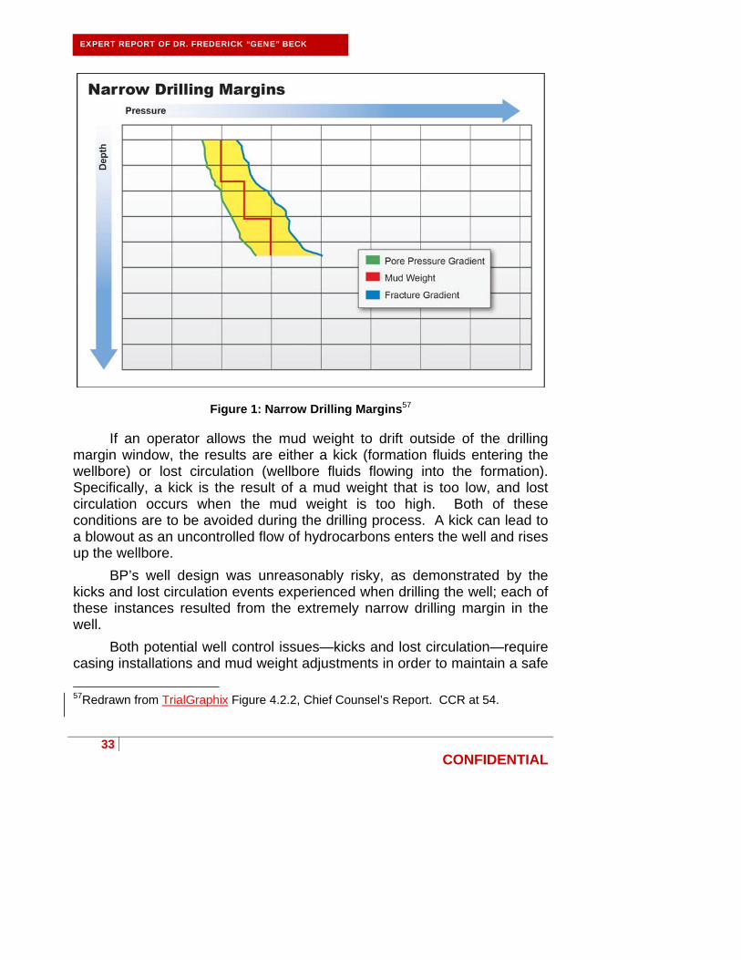
The difference between the pore pressure and the fracture pressure is commonly referred to as the “drilling margin.” The Chief Counsel’s Report includes a useful graphic, redrawn as Figure 1 below, which demonstrates the fundamental concept of drilling margin:
33
CONFIDENTIAL
EXPERT REPORT OF DR. FREDERICK “GENE” BECK
Figure 1: Narrow Drilling Margins57
If an operator allows the mud weight to drift outside of the drilling margin window, the results are either a kick (formation fluids entering the wellbore) or lost circulation (wellbore fluids flowing into the formation). Specifically, a kick is the result of a mud weight that is too low, and lost circulation occurs when the mud weight is too high. Both of these conditions are to be avoided during the drilling process. A kick can lead to a blowout as an uncontrolled flow of hydrocarbons enters the well and rises up the wellbore.
BP’s well design was unreasonably risky, as demonstrated by the kicks and lost circulation events experienced when drilling the well; each of these instances resulted from the extremely narrow drilling margin in the well.
Both potential well control issues—kicks and lost circulation—require casing installations and mud weight adjustments in order to maintain a safe
57Redrawn from TrialGraphix Figure 4.2.2, Chief Counsel’s Report. CCR at 54.

34
CONFIDENTIAL
EXPERT REPORT OF DR. FREDERICK “GENE” BECK
drilling margin. Safe drilling margins are mandated by 30 C.F.R. § 250.414(c), which states as follows:
30 C.F.R. § 250.414(c) (highlighting added).
The drilling margin dictates several design and operations decisions, including the parameters around which casing is designed, the number of casing strings required, and the depths at which casings strings are installed. For example, if a well is being drilled and a lost circulation event occurs, the mud weight exceeded the fracture pressure of the formation being drilled. The operator must take some action to prevent additional lost circulation events as mandated by 30 C.F.R. § 250.427:
35
CONFIDENTIAL
EXPERT REPORT OF DR. FREDERICK “GENE” BECK
30 C.F.R. § 250.427 (highlighting added). For example, to remedy a dangerously narrow drilling margin at a section of the well, the operator can install a casing string to isolate and protect this part of the formation, forming a barrier to drilling mud and isolating pore pressure at this part of the well.
BP’s well design was overly risky and resulted in repeated violations of the abovementioned regulations, including 30 C.F.R. § 250.427(b).
As drilling margins are typically narrow in a deep water drilling environment, attention must be given to ensure an adequate margin at all times while the well is drilled. Care must be given in making a realistic and accurate prediction of pore and fracture pressures and, once drilling commences, the pore pressure and fracture gradients actually encountered must be continuously evaluated. When narrow drilling margins are encountered, the installation of casing is usually required to reestablish an acceptable drilling margin in the well. Well designs must allow for a variance between the estimated and actual pore and fracture pressures by providing for additional, or contingency, casing strings to be installed.
On the Macondo well, instead of proceeding with caution by installing additional liners BP moved ahead with little or no drilling margin, ultimately damaging the well (i.e. cracking the formation) and compromising the cement job. BP could have chosen to isolate the higher pressure formations in the well with steel casing, including the 14.2 ppg (M57B) sand

36
CONFIDENTIAL
EXPERT REPORT OF DR. FREDERICK “GENE” BECK
zones, as shown in Figure 2 below. That would have enabled BP to continue drilling the well with a lower mud weight that would not have damaged the fragile 12.6 ppg (M56E) zone at the bottom of the well.
Revised Figure 2: Narrow Drilling Margin Remedy
But BP did not perform this narrow drilling margin remedy. The Macondo well as drilled was therefore damaged and dangerously unstable, and BP consistently lost drilling mud into the formation as it drilled the well. Specifically, the bottom portion of the Macondo well exhibited a pore pressure regression in which the pore pressure atypically decreased with depth, and BP failed to properly design or re-design the well to account for this regression. As discussed below, BP should have isolated the higher pressure formations at 17,467 feet (14.2 ppg) and 17,800 feet (13.1 ppg) such that it could have drilled the target formations near the bottom of the well (at 12.6 ppg) with a lower weight drilling mud. BP’s failure to address the pore pressure regression was unreasonable.
BP further failed to act as a prudent operator when the drilling margin for the final most critical hole section narrowed to the point that mud weight could no longer be safely adjusted without inducing either a kick or lost circulation. The result was massive mud losses to the formation. Lost circulation events established the upper limit of the drilling window as 14.3
Deleted: 8

37
CONFIDENTIAL
EXPERT REPORT OF DR. FREDERICK “GENE” BECK
ppg, and direct pore pressure measurements established the lower limit of pore pressure as 14.2 ppg.58 BP did not remedy the fact that it had no remaining drilling margin and all subsequent operations were extremely high risk with little to no margin for error.
B. BP acted unreasonably when it pumped heavy drilling mud with a high equivalent circulating density into the well without first repairing the damaged formation at the bottom of the well.
There are two types of pressures associated with the use of drilling mud in wells. These pressures depend on whether the fluid is static (not moving) or dynamic (moving or being circulated). The drilling fluid density determines static pressure. Dynamic pressures are created when drilling fluid is pumped (circulated) in the well. The dynamic pressure is additive to the static pressure and it is the pressure which causes the fluid to flow. For example, a static fluid at rest against a formation will exert a pressure against the formation based on the density of the fluid itself. However, once a fluid begins to flow (e.g., when the pumps are turned on and mud is circulated in the well), the flow of the fluid past the formation exerts an additional pressure on the formation. This additional, dynamic pressure is based on the amount of pressure that must be generated by the pumps to move the fluid. The dynamic pressure is related to (1) the physical properties of the fluid, such as density and viscosity, (2) the velocity of the fluid, and (3) geometry of the wellbore, including the internal dimensions of the casing and wellbore through which the fluid must be pumped.
The combination of the static and dynamic pressures is referred to as the equivalent circulating density. The equivalent circulating density also must be maintained within the drilling margin. When the drilling margin window becomes very narrow, the equivalent circulating density in the well becomes critical, and simple acts such as changing the speed of the mud pumps can create enough change in equivalent circulating density to cause either a kick or lost circulation. Equivalent circulating density management (controlling the magnitude and changes in equivalent circulating density) is
58 See, e.g., Bly Report at 17-19; National Academy of Engineering and National Research Council of the National Academies, Interim Report on the Causes of the Deepwater Horizon Oil Rig Blowout and Ways to Prevent Such Events at 5-7.

38
CONFIDENTIAL
EXPERT REPORT OF DR. FREDERICK “GENE” BECK
critical to many rig operations, including the installation of casing and successful cement placement.
BP failed to design and drill the Macondo well in a reasonable manner using techniques known throughout the drilling industry to maintain a safe drilling margin. When equivalent circulating densities are considered, BP had an increasingly narrow window in which to circulate fluids in the Macondo well. This narrow margin created an extremely unstable and unsafe wellbore that was unsuitable for the reliable installation of casing and placement of cement. BP could have placed additional casing in portions of the well to isolate fragile and high pressure sections of the well, thereby increasing the drilling margin to a safe level. But BP instead damaged the bottom fragile section of the well with heavy mud, resulting in fracturing and losses into the formation.
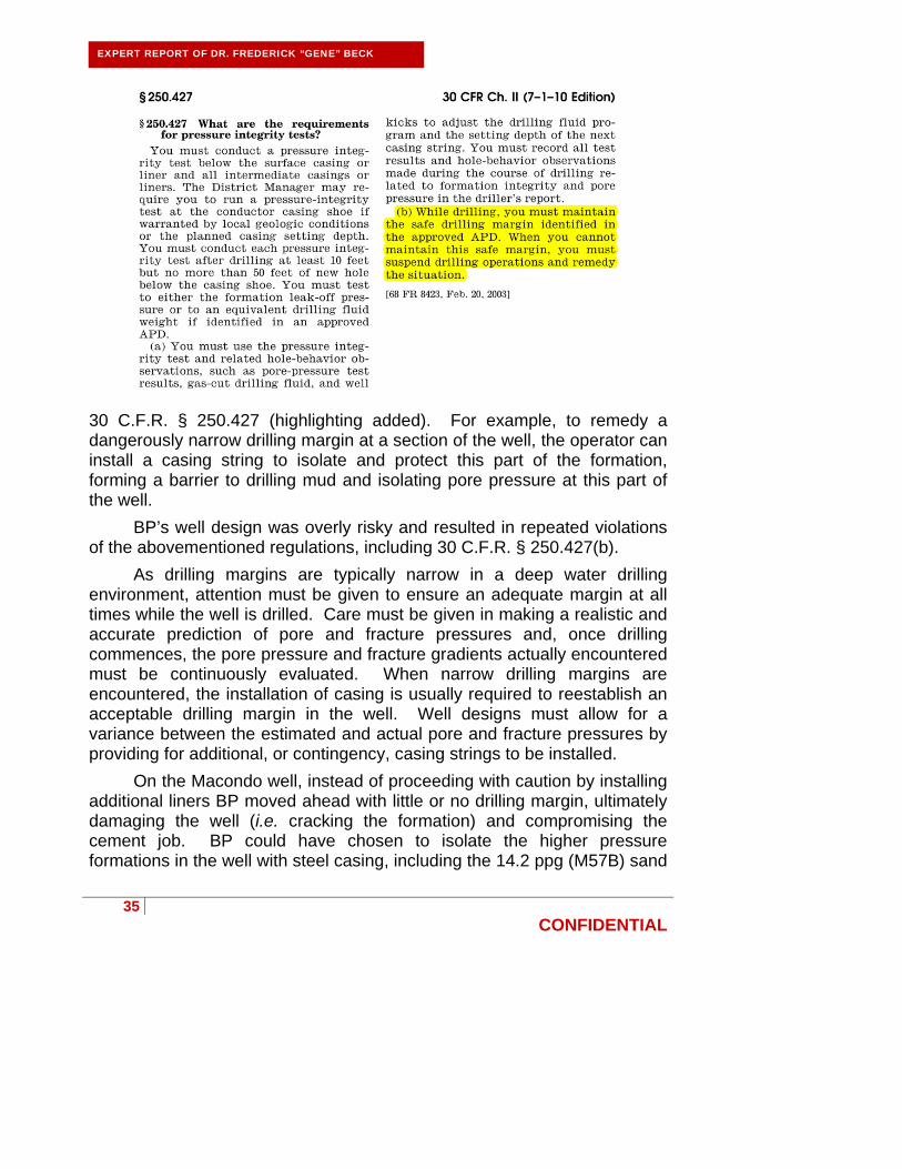
After BP damaged (i.e. cracked) formations at the bottom of the well, a prudent course of action would have been to repair the bottom of the well, thereby increasing the drilling margin to a safe level, before attempting to cement the final payzone. BP could have done this by first plugging the bottom of the well with cement, then setting a 7 inch liner just above the 12.6 ppg payzone, re-drilling the payzone with the correct mud weight, and finally setting a 5 inch liner across the payzone. By following this procedure and drilling with the correct mud weight, the formations would no longer be at risk of being damaged by drilling with excessive mud weight, a liner could be installed, and a reliable cement placement accomplished. In this condition, as shown in Figure 3 below, the entire open hole section of the Macondo well would have been cemented using mud weights that would have been easily circulated in the well.
39
CONFIDENTIAL
EXPERT REPORT OF DR. FREDERICK “GENE” BECK
Figure 3: Alternate Liner Design Repairing Well Bottom
Effective barriers would have been in place, allowing the well to be temporarily abandoned in a safe and prudent manner. I am not alone in recognizing that BP could have proceeded with well operations in an entirely different and more prudent manner.59
59 Rule 26 Report on BP’s Macondo Blowout Re: Oil Spill Commencing April 20, 2010 by the Oil Rig Transocean “Deepwater Horizon” in the Gulf of Mexico, Expert Opinion, Basis of Opinion, Analysis and Discussion, prepared by David Pritchard (hereinafter “Pritchard Expert Report”) at 12.

40
CONFIDENTIAL
EXPERT REPORT OF DR. FREDERICK “GENE” BECK
C. BP was imprudent in choosing to use a long string production casing.
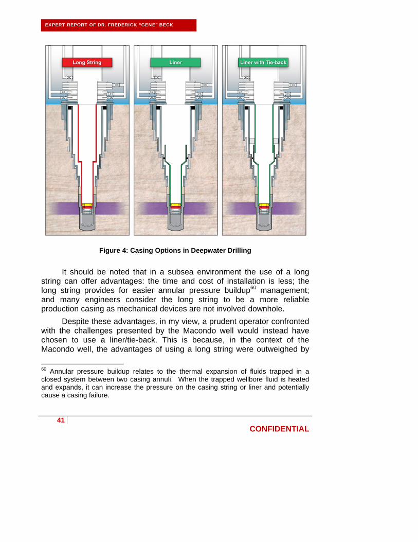
After a well has been drilled, the well operator typically installs additional tubing in the well that will enable it to move hydrocarbons from the target formations to the surface. These lengths of tubing are often referred to as production casing or production liners. BP had options in regard to the type of production casing it could use for the Macondo well. One option, a long string production casing, extends continuously from the seafloor to the bottom of the well. Another option, a liner, is run only a short distance from the bottom of the well to a selected height in the well. The liner is later “tied-back” to the surface with another length of production liner, but this operation is generally not performed until after the well is ready for production. If using a liner/tie-back for the Macondo well, BP would have set the short length of liner adjacent to the production zone and then move forward with temporary abandonment procedures. The tie-back would have been installed later, after a production platform replaced the Deepwater Horizon. These different casing options are shown in Figure 4 below:
41
CONFIDENTIAL
EXPERT REPORT OF DR. FREDERICK “GENE” BECK
Figure 4: Casing Options in Deepwater Drilling
It should be noted that in a subsea environment the use of a long string can offer advantages: the time and cost of installation is less; the long string provides for easier annular pressure buildup60 management; and many engineers consider the long string to be a more reliable production casing as mechanical devices are not involved downhole.
Despite these advantages, in my view, a prudent operator confronted with the challenges presented by the Macondo well would instead have chosen to use a liner/tie-back. This is because, in the context of the Macondo well, the advantages of using a long string were outweighed by
60 Annular pressure buildup relates to the thermal expansion of fluids trapped in a closed system between two casing annuli. When the trapped wellbore fluid is heated and expands, it can increase the pressure on the casing string or liner and potentially cause a casing failure.

42
CONFIDENTIAL
EXPERT REPORT OF DR. FREDERICK “GENE” BECK
significant disadvantages. Specifically, BP’s use of long string production casing: (1) increased the risk of cement contamination; (2) required the application of higher equivalent circulating densities to the fragile formations at the bottom of the well; and (3) only provided one potential independently tested barrier to annular flow. It appears that BP disregarded these risks and went with a long string design to save time and money.
1. BP increased the risk of cement contamination by using a long string production casing.
Use of a long string production casing increases the risks of cement contamination. In the Macondo well, cement had to be pumped through about 7,421 feet (1.4 miles) of 9-7/8 inch casing and about 5,816 feet (1.1 miles) of 7 inch casing (for a total of 2.5 miles) before it flowed into the liner annulus. Compared to alternatives, in which cement is instead pumped down much further through the drill pipe close to the desired location, the cement in the long string production casing was exposed to a much larger surface area in the 9-7/8 inch section of the liner before reaching its final destination.
Contact with the larger surface area increased the risk that the cement in the Macondo well would be contaminated by drilling mud that was not removed from the long string surface by the lead wiper plug. This problem associated with the long string production casing was magnified by the need to use wiper plugs capable of sealing and wiping against both the 9-7/8 inch and 7 inch liners in the long string. This made it very difficult for the wipers to adequately clean the interior of the long string casing, significantly increasing the risk of cement contamination. It would have been much simpler, and the wipers would have been much more reliable, if only one diameter of casing had needed to be wiped when the cement was pumped down the well.
In contrast, use of a liner/tie-back would have presented a much lower risk of cement contamination. As explained above, a liner-tie-back allows the last hole interval drilled to be covered with a relatively short section of casing (the liner). A second, longer section of liner (the tie-back) is installed later to “tie” the liner back to the surface. This is illustrated in Figure 5 below:
43
CONFIDENTIAL
EXPERT REPORT OF DR. FREDERICK “GENE” BECK
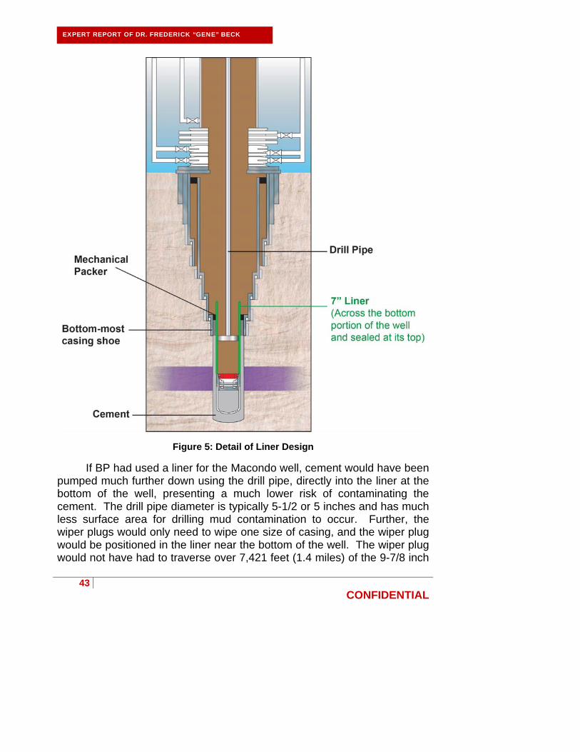
Figure 5: Detail of Liner Design
If BP had used a liner for the Macondo well, cement would have been pumped much further down using the drill pipe, directly into the liner at the bottom of the well, presenting a much lower risk of contaminating the cement. The drill pipe diameter is typically 5-1/2 or 5 inches and has much less surface area for drilling mud contamination to occur. Further, the wiper plugs would only need to wipe one size of casing, and the wiper plug would be positioned in the liner near the bottom of the well. The wiper plug would not have had to traverse over 7,421 feet (1.4 miles) of the 9-7/8 inch
44
CONFIDENTIAL
EXPERT REPORT OF DR. FREDERICK “GENE” BECK
liner plus about 5,816 feet (1.1 miles) of 7 inch casing (for a total of 2.5 miles) as did the long string in BP’s design. A liner for the Macondo well would only have needed to be 1,500 feet in length, so the wiper plugs would have only had to travel that distance (i.e. 0.28 miles as opposed to 2.5 miles); the remaining 11,800 feet of casing could have been installed in a reliable manner, without the increased risk of lost circulation.
2. BP required the application of higher equivalent circulating densities to the fragile formations at the bottom of the well by using a long string production casing.
Another drawback to BP’s use of the long string production casing was the increased pressures required to circulate the cement up the wellbore annulus. Cement programs must be designed so that cement can be pumped all the way to the bottom of the well, out the shoe, and then up the wellbore annulus between the production casing or liner and the walls of the formation. As the cement moves into the annulus, it displaces drilling mud already present in the annulus, pushing it up towards the top of the well.
The smaller the annular space into which the cement/mud must be moved, the higher the pressures required to actually pump the cement/mud into the annulus. BP’s long string production casing included a long (7,241 feet/1.4 miles) section of 9-7/8 inch casing that filled much of the wellbore annulus around it. The annular space into which mud had to be displaced was thus relatively tight compared to a well design using a liner/tie-back. The higher pumping pressures required to pump the cement and mud up the annulus led to higher equivalent circulating densities at the bottom of the well, which increased the risk of cement failure due to formation damage. This was because higher equivalent circulating densities mean additional pressure applied to downhole formations, and these pressures can fracture the formations and allow lost circulation or cross flow in which hydrocarbons flow into the well.
In contrast, had BP elected to use a liner/tie-back, the equivalent circulating densities necessary to place cement would have been lower. The annular space created by a 5-1/2 inch drill pipe is much larger than that created by the 9-7/8 inch long string production casing, providing more annular space into which mud can be displaced, lowering the equivalent circulating density. This would have led to a less risky well design, as lower equivalent circulating densities reduce the risk of lost circulation.
45
CONFIDENTIAL
EXPERT REPORT OF DR. FREDERICK “GENE” BECK
3. BP failed to provide two independently tested barriers to annular flow by using a long string production casing.
BP’s use of a long string production casing was also unsound because it rendered the annular cement incapable of being directly pressure tested and proven as a barrier. Use of a long string production casing design in a subsea well does not allow for two independently tested barriers along the annular flow path from the reservoir to the seafloor.
In contrast, a liner/tie-back would have provided a safer design with multiple annular flow barriers that could have been independently tested. First, cement that could be independently tested would have been placed around the entire periphery of the liner, blocking annular flow. Then a packer (a barrier device that is either mechanically or hydraulically expanded or inflated to form an annular barrier in a well) would have been installed between the 7 inch liner and the 9-7/8 inch casing, forming a second barrier to annular flow that could be independently tested. With the tie-back casing installed and cemented, the hanger seal assembly would have provided another barrier that could be independently tested. Additionally, as an alternative to installing a tie-back at that point, a cement plug could have been placed across the interior of the upper casing to provide another barrier that could be independently tested.
4. BP went with the riskier long string design for financial reasons.
BP’s original well design called for a long string production casing but, after experiencing multiple lost circulation events, BP considered using a liner instead of a long string, recognizing that a liner would result in a lower equivalent circulating density and would thus be safer.61 This was indicated in an email exchanged between BP’s Brian Morel and Richard Miller on April 14, 2010, six days before the blowout:
61 CCR at 61, n. 66 (citing David Sims (BP) interview with Commission Staff, 12/14/2010; Gregg Walz, interview with Commission Staff, 10/6/2010); BP-HZN-MBI00127266-67.

46
CONFIDENTIAL
EXPERT REPORT OF DR. FREDERICK “GENE” BECK
Depo. Ex. 126 at CON67 (highlighting added). At the instruction of BP engineering manager Jonathan Sprague, Richard Miller, BP’s casing design specialist, even determined that a liner would work to manage potential annular pressure buildup, concluding that “[a]ll looks fine.”62
However, as outlined in one of BP’s management of change documents, BP found that using a long string instead of a liner would save $7 million to $10 million:
Depo. Ex. 2659 at BP-HZN-MBI00143259 (highlighting added). In considering these cost savings, BP acknowledged that the use of a long string could result in lost circulation and create further complications during cementing.63 Nevertheless, BP proceeded to run the riskier long string because it concluded that doing so would result in “the best economic case” for the well.64
62 Depo. Ex. 126 at CON67. 63 Depo. Ex. 901.
64 Depo. Ex. 2659 (BP-HZN-MBI00143259).

47
CONFIDENTIAL
EXPERT REPORT OF DR. FREDERICK “GENE” BECK
As was the case with a number of its other decisions pertaining to the Macondo well, BP didn’t make this decision until the last minute. This pattern of behavior made BP well design engineers like Richard Miller nervous, as expressed in the following email from Miller to BP’s Mark Hafle five days before the blowout:
Depo. Ex. 126 at CON67 (highlighting added). The last minute flurry of activity leading to the adoption of the long string design reflected that BP was “flying by the seat of [their] pants,” as expressed in the following email between BP’s John Guide and BP’s David Sims three days before the blowout:
Depo. Ex. 795 at BP-HZN-BLY00097031 (highlighting added).
In sum, BP’s drilling engineers on the Macondo well were already faced with a fragile bottom hole formation in which BP had experienced repeated instances of lost returns. BP’s selection of a long string

48
CONFIDENTIAL
EXPERT REPORT OF DR. FREDERICK “GENE” BECK
production casing constituted an unsound design choice because it increased the risk of cement contamination, lost circulation, and precluded the installation of two independently tested barriers to annular flow. As explained by BP’s drilling engineering team leader, Greg Walz, these risks required BP’s Macondo team to adjust variables in its cement job to justify the use of a long string as opposed to a liner:
G. Walz Depo., 4/21/2011 at 404:8–12. A prudent operator, facing the “nightmare” Macondo well, would have done just the opposite—selected the completion technique (i.e. a liner) that would have produced the safest, most effective cement job.
D. BP misidentified the uppermost hydrocarbon-bearing zone, and consequently achieved neither proper zonal isolation nor effective management of annular pressure buildup in the Macondo well.
In designing a well, well operators consider both zonal isolation and annular pressure buildup management, both of which can be safety concerns. Proper zonal isolation in a well is critical because it ensures the isolation and containment of hydrocarbon-bearing zones. Annular pressure buildup is pressure buildup in the annulus that may create a pressure differential large enough to collapse the production casing. Poor annular pressure buildup management may lead to lost production in the well, and can be catastrophic. Because BP misidentified the uppermost hydrocarbon-bearing zone in the well, BP’s well design failed to achieve either proper zonal isolation or effectively manage annular pressure buildup concerns.
1. BP misidentified the uppermost hydrocarbon-bearing zone.

49
CONFIDENTIAL
EXPERT REPORT OF DR. FREDERICK “GENE” BECK
BP petrophysicist Galina Skripnikova misidentified the uppermost hydrocarbon-bearing zone in the Macondo well as being located at approximately 17,803 feet in the following email to BP personnel seven days before the blowout:
Depo. Ex. 3512 at BP-HZN-MBI 00126428 (highlighting added). I understand that the evidence suggests that the uppermost zone was actually much higher at 17,467 feet (the M57B sand). Evidence shows that BP was aware of the hydrocarbon-bearing nature of the M57B sand as early as 2009, as seen in the following email exchange among BP personnel:
Depo. Ex. 5254 at BP-HZN-2179MDL02584729 (highlighting added). Dr. Skripnikova testified that on the day of the blowout she and her team made the determination that the M57B sand was “probable gas.”65 Additionally,
65 G. Skripnikova Depo., 7/7/2011 at 211:18 - 212:16 (note that the deposition transcript inaccurately reflects the depth of 17,467 as “14,467”).

50
CONFIDENTIAL
EXPERT REPORT OF DR. FREDERICK “GENE” BECK
the following e-mail from BP’s Kent Corser66 sent after the blowout shows similar knowledge of the M57B zone.
Depo. Ex. 2727 at 1 (highlighting added, handwritten notes in original). Despite having this knowledge, BP ignored the existence and location of the M57B zone and failed to report it to the Minerals Management Service67 or to Halliburton.
2. Because BP misidentified the uppermost hydrocarbon-bearing zone, BP failed to follow both its own guidelines and violated a federal regulation concerning zonal isolation.
Given that BP misidentified the uppermost hydrocarbon-bearing zone in the Macondo well, BP’s well plan placed only 167 feet of cement over the uppermost hydrocarbon-bearing zone. This cement placement failed to follow BP’s own zonal isolation requirements, violated a federal regulation, and failed to achieve proper zonal isolation.
Even if BP’s Skripnikova had been correct in identifying the sand at 17,800 feet as the uppermost hydrocarbon-bearing zone, BP still was deviating from its own guidelines in ETP GP 10-60, which mandated that the top of cement be located 1000 feet further up the hole at 16,800 feet.68 BP’s own Bly Report estimated that the top of cement was only at 17,260 feet69—460 feet short of BP’s internal guideline for top of cement in subsea
66 Mr. Corser served on BP’s accident investigation team. See, e.g., Depo. Ex. 224.
67 F. Patton Depo., 7/14/2011 at 445:13-446:17.
68 Depo. Ex. 6121 at BP-HZN-BLY00034587.
69 Bly Report at 19, Fig. 3.

51
CONFIDENTIAL
EXPERT REPORT OF DR. FREDERICK “GENE” BECK
wells. This failure to follow BP’s ETP GP 10-60 guideline is even more significant when considered in view of the M57B high-pressure (14.2 ppg) sand located at 17,467 feet (more than 300 feet further up the well), making the estimated top of cement 760 feet short of BP’s specification.
Additionally, 30 C.F.R. § 250.421 mandates at least 500 feet of cement above the top of the uppermost hydrocarbon-bearing zone. If BP had disclosed the M57B zone, this federal regulation would have required the top of cement to be at least 16,967 feet. BP instead estimated the top of cement to be at only 17,260 feet and designed the top of cement to be only at 17,300 in violation of this regulation given the location of the M57B zone. If the existence of the shallowest hydrocarbon bearing zone at 17,467 feet (the M57B zone) had been acknowledged, BP could not have initiated pumping of the cement job as planned without violating a federal regulation.
3. Because BP misidentified the uppermost hydrocarbon-bearing zone, BP failed to effectively manage annular pressure buildup.
Had BP acknowledged the shallower M57B zone and placed the top of cement at least 500 feet above that zone as required by 30 C.F.R. § 250.421, BP could not have pumped the cement as designed without also being in violation of its guidelines for annular pressure buildup management, because BP would have covered up the intended pressure release path with annular cement. Instead BP would have had to significantly redesign the well to meet its annular pressure buildup specifications.
Annular pressure buildup relates to the thermal expansion of fluids trapped in a closed system between two casing annuli. When the trapped wellbore fluid is heated and expands it increases the pressure on the casing string or liner and can potentially cause a casing failure. Closed spaces subject to such pressure buildup can be formed during the cementing process. Fluids trapped in this annulus can heat up and expand during, for example, the onset of production of hydrocarbons from the well. As the hydrocarbons flow up the well, the fluids and gases trapped in the annular spaces can exert pressure on the production casing. The well can fail when the annular pressure buildup in the trapped annuli create a pressure differential large enough to collapse the production casing. This can result in the total loss of the well.
52
CONFIDENTIAL
EXPERT REPORT OF DR. FREDERICK “GENE” BECK
Of BP’s generally available annular pressure buildup mitigation strategies,70 BP intended to use two for the Macondo well: (1) open shoes; and (2) rupture disks. 71 Of these two, open shoes most influenced BP’s cement design. Open shoes are the result of “cement shortfall,” which is the concept of leaving open hole between the bottom of the lowermost casing string and the top of cement of the well bottom cement job. This leaves a built-in pressure relief path in the annulus outside of the long string production casing. If annular pressure buildup causes pressure to build up in the annulus, the formation will form localized fractures so that the pressure can be vented before the casing collapse pressure is exceeded.
BP acknowledging the M57B zone would have called for a top of cement of at least 16,967 feet, which would have placed the top of cement over the bottommost casing shoe and precluded BP’s use of cement shortfall as a means of managing annular pressure buildup. BP would have had to significantly redesign the well to manage annular pressure buildup by other means.
E. BP imprudently elected not to use a float shoe to provide an additional barrier in the shoe track.
BP imprudently elected not to use a float shoe to provide an additional, if temporary, barrier to flow up the shoe track. The importance of the shoe track with respect to well control and cementing cannot be overstated. The purpose of the shoe track is to create stable conditions for cement to cure. This is routinely achieved in two ways. First, check valves when installed in the casing prevent flow up the casing. Second, if the cement is mixed to be denser than the drilling fluid, the hydraulic pressure from the column of cement on the outside of the casing (the annulus) traps cement in the shoe track against the check valve. If a check valve is placed some distance up the casing (usually about 80 feet), a column of clean cement will be left in the shoe track. Once the cement cures a dependable flow barrier is created.
This process is extremely important for successful cementing, and most engineers choose to install a redundant set of check valves in the
70 BP-HZN-2179MDL02800023 at 2800030.
71 BP-HZN-2179MDL02800023 at 2800030.

53
CONFIDENTIAL
EXPERT REPORT OF DR. FREDERICK “GENE” BECK
shoe track—one set in a float collar and another set in a float shoe. Float collars and float shoes are often built with two check valves each, creating additional redundancy. Installing a check valve at the very bottom of the casing string by way of a float shoe has the benefit of preventing drilling mud or formation fluids from entering the shoe track casing, potentially compromising the shoe track cement job, as shown in Figure 6 below.
Figure 6: Available Mechanical Barriers to Flow

54
CONFIDENTIAL
EXPERT REPORT OF DR. FREDERICK “GENE” BECK
Nevertheless, despite the fact that the Macondo well was a “nightmare well,”72 BP elected not to use a float shoe. In doing so, BP imprudently removed a potential barrier to hydrocarbon flow, despite the fact that BP had regularly taken gas kicks and the fact that so much gas had previously reached the rig floor that BP ordered Transocean to disable the general gas alarms on the drilling floor.73
VII. BP Failed To Prudently Manage Operations And Made Several Decisions That Caused The Blowout.
A. BP drilled an unstable wellbore.
The wellbore as drilled by BP was unstable. There were massive mud losses to the formation and the well faced a constant threat of kicks. The mud weight could not be adjusted up or down without inducing losses or a kick. This made the well an extremely difficult environment in which to install casing and cement it in place. Although BP managed to get the casing into position, it took unnecessary chances in doing so. As discussed above, BP could and should have designed and drilled the well much more safely by adding casing to the higher pressure portions of the bore hole, thereby increasing the drilling margin.
B. BP acted unreasonably when it decided to use only six centralizers despite Halliburton’s recommendation of at least twenty-one centralizers.
Centralizers on a casing string are used to create uniform clearance between the casing and the drilled hole. Adequate centralization ensures an optimal path for fluid flow during mud conditioning (i.e. bottoms-up circulation) and cementing. Inadequate centralization results in casing that is not centered and subject to “channeling.” Channeling refers to a situation where cement flows preferentially up the path of least resistance (the larger spaces in the annulus) and more slowly or not at all in the narrower annular space. The result is channels of drilling mud through which pressurized hydrocarbons can flow and which have the potential to
72 Depo. Ex. 126 at CON67; President’s Report at 2.
73 M. Williams Depo., 7/20/11 at 150:16-151:14; Tr. of USCG/MMS Investigation (M. Williams testimony), 7/23/2010 at 30:4-15, 33:6-10; FRCP Rule 26 Report of Geoff Webster, 8/26/2011 at 3.
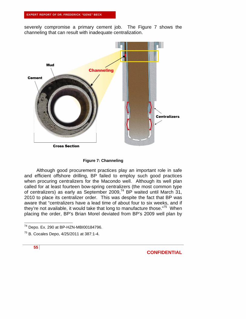
55
CONFIDENTIAL
EXPERT REPORT OF DR. FREDERICK “GENE” BECK
severely compromise a primary cement job. The Figure 7 shows the channeling that can result with inadequate centralization.
Figure 7: Channeling
Although good procurement practices play an important role in safe and efficient offshore drilling, BP failed to employ such good practices when procuring centralizers for the Macondo well. Although its well plan called for at least fourteen bow-spring centralizers (the most common type of centralizers) as early as September 2009,74 BP waited until March 31, 2010 to place its centralizer order. This was despite the fact that BP was aware that “centralizers have a lead time of about four to six weeks, and if they’re not available, it would take that long to manufacture those.”75 When placing the order, BP’s Brian Morel deviated from BP’s 2009 well plan by
74 Depo. Ex. 290 at BP-HZN-MBI00184796. 75 B. Cocales Depo, 4/25/2011 at 387:1-4.

56
CONFIDENTIAL
EXPERT REPORT OF DR. FREDERICK “GENE” BECK
ordering only 7-10 centralizer subs (instead of the fourteen or more bow-spring centralizers called for by the well plan) from BP’s supplier.76 Because BP’s supplier had only six centralizer subs in stock, BP purchased just six centralizer subs at that time, making no effort to procure additional centralizers from alternate suppliers.77 As a result of these poor procurement practices, BP was unprepared to correctly centralize the casing.
On April 15, after learning that BP intended to run only six centralizers in the well, Halliburton’s Jesse Gagliano used Halliburton’s OptiCem™ simulation software to model the well with six centralizers.78 Gagliano immediately informed BP engineers that his modeling with OptiCem™ demonstrated “that there would be a channeling issue with the design.”79 After working with BP engineers to model various centralizer scenarios, Gagliano recommended at least twenty-one centralizers for the well.80 Based on Gagliano’s recommendation, BP procured fifteen slip-on centralizers (in addition to the six centralizer subs that BP already had) for delivery on April 16.81 However, the additional centralizers went unused after BP personnel disagreed over whether the new slip-on centralizers were suitable for the job.82 Significantly, BP’s own Bly Report later
76 Depo. Ex. 2576 at BP-HZN-MBI00117524. 77 CCR at 104 (citing Bryan Clawson (Weatherford), interview with Commission staff, 10/28/2010; BP-HZN-MBI 252278); BP-HZN-BLY00066450-51 at 450; D. Smith Depo., 05/23/2011 at 114:12-25 (stating that six centralizers were available to BP and that he does not recall any discussion of the availability of additional centralizers).
78 Tr. of USCG/MMS Investigation (J. Gagliano Testimony), 8/24/2010 at 397:8-22; Depo. Ex. 1685. 79 Tr. of USCG/MMS Investigation (J. Gagliano Testimony), 8/24/2010 at 319:1-6. 80 Tr. of USCG/MMS Investigation (J. Gagliano Testimony), 8/24/2010 at 320:5-12. 81 Depo. Ex. 1685; Purchase order at BP-HZN-2179MDL02096397; Tr. of USCG/MMS Investigation (J. Gagliano Testimony), 8/24/2010 at 320:5-19; G. Walz Depo., 4/21/2011 at 142:22-143:12; B. Cocales Depo, 4/25/2011 at 239:7-11 and 380:14-17; B. Cocales Depo., 4/26/2011 at 807:10-11 (“I knew these were slip-ons.”). 82 Depo. Ex. 1687; Depo. Ex. 2579 at BP-HZN-2179MDL00081605-06; Depo. Ex. 1689 at BP-HZN-2179MDL00081650-1; B. Cocales Depo., 4/26/2011 at 594:1-5 and 814:22-24.
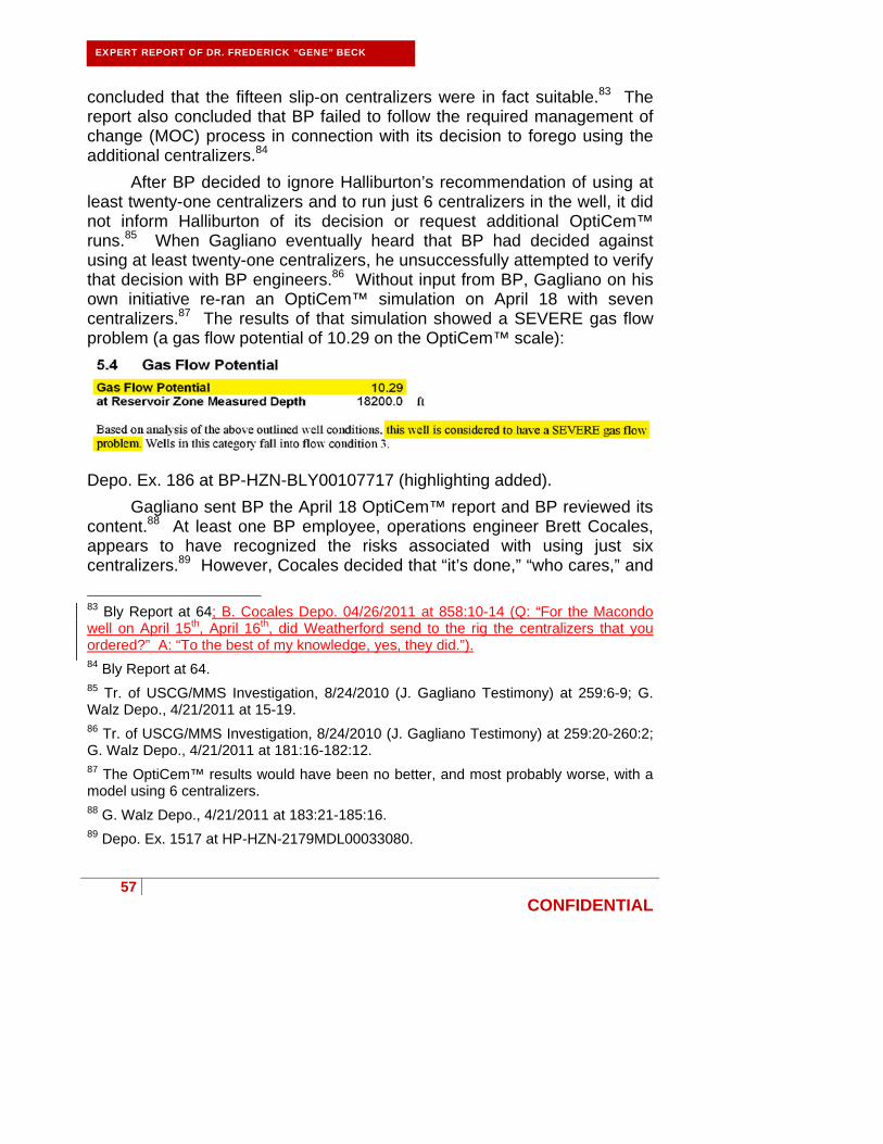
57
CONFIDENTIAL
EXPERT REPORT OF DR. FREDERICK “GENE” BECK
concluded that the fifteen slip-on centralizers were in fact suitable.83 The report also concluded that BP failed to follow the required management of change (MOC) process in connection with its decision to forego using the additional centralizers.84
After BP decided to ignore Halliburton’s recommendation of using at least twenty-one centralizers and to run just 6 centralizers in the well, it did not inform Halliburton of its decision or request additional OptiCem™ runs.85 When Gagliano eventually heard that BP had decided against using at least twenty-one centralizers, he unsuccessfully attempted to verify that decision with BP engineers.86 Without input from BP, Gagliano on his own initiative re-ran an OptiCem™ simulation on April 18 with seven centralizers.87 The results of that simulation showed a SEVERE gas flow problem (a gas flow potential of 10.29 on the OptiCem™ scale):
Depo. Ex. 186 at BP-HZN-BLY00107717 (highlighting added).
Gagliano sent BP the April 18 OptiCem™ report and BP reviewed its content.88 At least one BP employee, operations engineer Brett Cocales, appears to have recognized the risks associated with using just six centralizers.89 However, Cocales decided that “it’s done,” “who cares,” and
83 Bly Report at 64; B. Cocales Depo. 04/26/2011 at 858:10-14 (Q: “For the Macondo well on April 15th, April 16th, did Weatherford send to the rig the centralizers that you ordered?” A: “To the best of my knowledge, yes, they did.”). 84 Bly Report at 64. 85 Tr. of USCG/MMS Investigation, 8/24/2010 (J. Gagliano Testimony) at 259:6-9; G. Walz Depo., 4/21/2011 at 15-19. 86 Tr. of USCG/MMS Investigation, 8/24/2010 (J. Gagliano Testimony) at 259:20-260:2; G. Walz Depo., 4/21/2011 at 181:16-182:12. 87 The OptiCem™ results would have been no better, and most probably worse, with a model using 6 centralizers. 88 G. Walz Depo., 4/21/2011 at 183:21-185:16. 89 Depo. Ex. 1517 at HP-HZN-2179MDL00033080.

58
CONFIDENTIAL
EXPERT REPORT OF DR. FREDERICK “GENE” BECK
that the poor centralization “will probably be fine” because he understood that Halliburton would have the opportunity to perform remedial cementing if the primary cement job channeled:
Depo. Ex. 1517 at BP-HZN-2179MDL00033080 (highlighting added).
Significantly, Gagliano’s April 18 OptiCem™ results were premised on the highest hydrocarbon bearing sand actually disclosed by BP. BP, as well operator, was the only entity with access to all pertinent well information and, as discussed above, BP withheld from Halliburton the location of the actual uppermost hydrocarbon bearing sand (the M57B zone).90 This rendered Gagliano unable to account for the M57B zone in his April 18 OptiCem™ simulation. If BP had provided the M57B data to Gagliano, his April 18 OptiCem™ would have predicted a CRITICAL gas flow problem (a gas flow potential of 54.85 on the OptiCem™ scale), more than five times the gas flow potential of 10.29 using the highest sand disclosed by BP (the sand at 17,800 and 12.6 ppg).91 Moreover, in a CRITICAL gas flow situation, OptiCem™ provides additional warning and instruction:
90 Depo. Ex. 2727 at BP-HZN-2179MDL00323685. 91 An OptiCem™ simulation was run based on the same data Gagliano used in the April 18, 2010 report but using the M57B as the reservoir.

59
CONFIDENTIAL
EXPERT REPORT OF DR. FREDERICK “GENE” BECK
HAL_1144047 (highlighting added). This evidence indicates that the condition of the Macondo well was riskier than what was demonstrated by Gagliano’s April 18 simulation premised on the highest sand disclosed by BP and that BP should have re-designed the production casing. Instead BP withheld critical well data regarding the location of the M57B zone from Halliburton in order to save time and money and went forward with its placement of just six centralizer subs.92
BP’s centralizer placement failed to comply with BP’s written practice requiring “at least 30m (100 ft) of centralized pipe above the distinct permeable zone.”93 As shown below, BP’s placement of the six centralizers in the Macondo well appears to have been random and did not centralize the pipe at 17,804’ where BP (erroneously) identified the uppermost pay sand M56A (see Figure 9 below). Gagliano’s twenty-one centralizer plan, in contrast, placed each centralizer 45 feet apart and properly centralized the drill pipe at, above, and below the M56A zone (see Figure 8 below).
92 G. Walz Depo., 4/21/2011 at 408:17-409:1, 409:12-410:1, and 412:6-413:13. 93 Depo. Ex. 184 at BP-HZN-2179MDL00269667 (when a cement bond log is not run which is the case here).

60
CONFIDENTIAL
EXPERT REPORT OF DR. FREDERICK “GENE” BECK
Revised Figure 8: Halliburton’s Gagliano Recommendation: Normal Centralizer Placement and Parameters
Revised Figure 9: BP’s Actual Placement: Lack of Centralizers May Result in Low Stand-off Ratio

61
CONFIDENTIAL
EXPERT REPORT OF DR. FREDERICK “GENE” BECK
Additionally, although BP knew that Halliburton could run an OptiCem™ simulation to determine optimal placement of the centralizers and that OptiCem™ was the only available tool to conduct such an analysis, BP did not ask Halliburton to do so.94
BP acted unreasonably when it failed to timely procure sufficient centralizers to properly centralize the casing, withheld pertinent well information from Halliburton, ignored Halliburton’s recommendation of at least twenty-one centralizers, installed only six centralizers, and failed to adequately centralize the casing. This conduct was not consistent with the conduct that would be expected from a prudent well operator.
BP’s persistence with its decision to use only six centralizers created conditions that adversely affected the likelihood of success of the cement placement in the well and subsequent zonal isolation.
C. BP chose not to convert the auto-fill float collar at the safest position in the wellbore.
To get the casing into place, BP ran an auto-fill float collar, which reduces the surge pressures placed on the well during the lowering of the casing into the well. In non-compliance with the written practices set forth in BP’s specification DWOP § 15.2.15, BP did not attempt to convert the float collar to “conventional” mode until it was lowered to the bottom of the well. When the float collar is converted to conventional mode, the check valves in the collar are closed and thus prevent flow from entering the casing. Closing the check valves prior to lowering the casing with the float collar to the bottom of the well increases the surge pressure on the wellbore for a short time, but is much safer from a well control standpoint, as a kick is prevented from entering the casing. Closing the check valves prior to lowering the casing into the open well bore at the bottom of the well also prevents debris such as formation cuttings, lost circulation material, or filter cake in the open well bore from entering the inside of the casing. Debris can cause the casing and/or float equipment to become plugged.
The decision not to convert the auto-fill collar prior to entering open bore hole at the bottom of the well was driven by the fact that BP chose to install the casing as a long string, and the auto-fill collar was central to BP’s
94 G. Walz Depo., 4/21/2011 at 166:7-10.

62
CONFIDENTIAL
EXPERT REPORT OF DR. FREDERICK “GENE” BECK
plans for equivalent circulating density management. Because equivalent circulating density is highest with a long string casing configuration, reliance upon the auto-fill collar to reduce surge (and thus equivalent circulating density) while lowering the casing, forced BP to take additional risk by delaying the conversion until the casing was on bottom. In my opinion, the float collar should have been converted prior to running the casing into open hole. BP could have then confirmed that the check valves in the float collar were indeed functioning and could then proceed with confidence that an effective barrier was in place in the casing string, prior to exposing the shoe track to potential debris and hydrocarbons in the open hole.
Had the casing been installed as a liner, surge on the well would have been minimized and the effect of a converted float collar at the bottom of a liner would have been far less than that at the bottom of a long string, so that the increased surge by shutting the float valves prior to entering the open hole would not have been as much of a concern. Regardless of the casing configuration, the auto-fill collar should have been converted prior to the casing being run into the open hole.
D. BP likely damaged the float collar.
BP included a float collar in the long string production casing in order to hold the cement in a static condition after the cement had been pumped into the well. However, BP was reckless in attempting to convert the float collar into a one way valve (to close its valves to block flow up the casing) as intended in the well design. BP’s recklessness came with the following consequences:
BP likely damaged and failed to convert the float collar, thus removing a barrier that would have prevented the blowout of the Macondo well;
The damaged and unconverted float collar enabled cement to u-tube in the long string production casing, extending the cement setting time or potentially keeping the shoe track cement from setting at all; and
BP’s recklessness in attempting to convert the float equipment may have also damaged the shoe track, compromising the shoe track cement placement and effectiveness.
BP used a float collar with valves on the Macondo well to prevent “u-tubing” of cement. U-tubing is a term that describes how cement that has
63
CONFIDENTIAL
EXPERT REPORT OF DR. FREDERICK “GENE” BECK
been pumped into the well moves because of differential pressures between the interior of the casing string and the annulus on the outside the casing. U-tubing relates to any movement, even very small movements, of the cement caused by the pressure differential. U-tubing occurs when the cement has started to rise from the shoe and it imparts a higher hydrostatic pressure back toward the shoe. This pressure difference is what can cause the cement to u-tube back into the casing.
When cementing a well, the cement is typically pumped down the inside of the casing, out through the shoe, and then back up the annulus on the outside of the casing and towards the surface. In order to accomplish the desired result (i.e. cement in the annulus providing zonal isolation for the target formation) the well must be designed in such a way to prevent u-tubing. This is because any movement of the cement can delay or prevent the cement from setting.
In order to prevent u-tubing and keep the cement in place in the annulus long enough for it to set, it is necessary to have a device that serves as a check valve to prevent the cement from reentering the casing and to keep the cement in a static state. This is the purpose of the float equipment, including the float valve used in the Macondo well. Float equipment is critical for the placement of cement, holding the cement in place, and allowing cement to set in a static condition. Specifically, properly functioning float equipment is a necessary pre-condition to a successful cement job. Float equipment may be a float collar and/or a float shoe, and in most wells both are run.
Figure 10 shows u-tubing:

64
CONFIDENTIAL
EXPERT REPORT OF DR. FREDERICK “GENE” BECK
Figure 10: U-Tubing
A shoe is a component positioned at the bottom of a casing string that is typically used to guide the casing or liner into the wellbore. For example, a reamer shoe was used at the bottom of the long string production casing in the Macondo well. A commonly used type of shoe, a float shoe, contains a check valve assembly that prevents fluids from flowing up into the casing string when the casing string is being installed into the well and during the cementing process.95
95 Schlumberger Oilfield Glossary definition for “float shoe” found at http://www.glossary.oilfield.slb.com/DisplayImage.cfm?ID=502.

65
CONFIDENTIAL
EXPERT REPORT OF DR. FREDERICK “GENE” BECK
A float collar is a component installed near the bottom of the casing string, at the top of the shoe track, that usually contains one or more check valves called float valves. The float valves allow fluid to flow both up and down the casing when the float collar is in the unconverted position, and when the float collar is converted the float valves are closed and will allow fluid flow in the downward direction only. The purpose of the float valves is to prevent the backflow of cement up the casing during the cementing operation (i.e. u-tubing), and by holding back the cement, also preventing the flow of hydrocarbons below the cement up the casing.
BP purchased a Weatherford M45AP float collar from Nexen Petroleum for use in the Macondo well,96 which is depicted in the following figure. BP did not use a float shoe in the Macondo well, but instead used a reamer shoe, a shoe without any check valve inside.
96 Depo. Ex. 2446 at NEX000051.

66
CONFIDENTIAL
EXPERT REPORT OF DR. FREDERICK “GENE” BECK
Figure 11: Weatherford M45AP Float Collar Used In Macondo Well97
The Weatherford M45AP is an auto-fill type float collar. “Auto-fill” means that the check valve feature of the collar is held open while running in the hole to automatically fill up the casing and to prevent increasing the pressure on the formations to be cemented (called “surging” the formation) which could fracture the formation and prematurely cause a hydrocarbon kick or lost circulation. The Weatherford M45AP float collar used by BP has a phenolic resin auto-fill tube that holds two aluminum flapper-type check valves in an open position. Inside the auto-fill tube is a high density ball that is held in place at the top by three fingers and on the bottom by a
97 Depo. Ex. 2582 at WFT-MDL00020470.
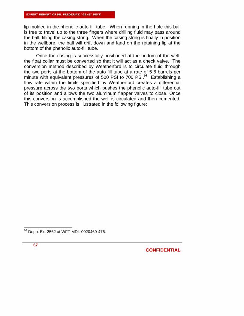
67
CONFIDENTIAL
EXPERT REPORT OF DR. FREDERICK “GENE” BECK
lip molded in the phenolic auto-fill tube. When running in the hole this ball is free to travel up to the three fingers where drilling fluid may pass around the ball, filling the casing string. When the casing string is finally in position in the wellbore, the ball will drift down and land on the retaining lip at the bottom of the phenolic auto-fill tube.
Once the casing is successfully positioned at the bottom of the well, the float collar must be converted so that it will act as a check valve. The conversion method described by Weatherford is to circulate fluid through the two ports at the bottom of the auto-fill tube at a rate of 5-8 barrels per minute with equivalent pressures of 500 PSI to 700 PSI.98 Establishing a flow rate within the limits specified by Weatherford creates a differential pressure across the two ports which pushes the phenolic auto-fill tube out of its position and allows the two aluminum flapper valves to close. Once this conversion is accomplished the well is circulated and then cemented. This conversion process is illustrated in the following figure:
98 Depo. Ex. 2562 at WFT-MDL-0020469-476.
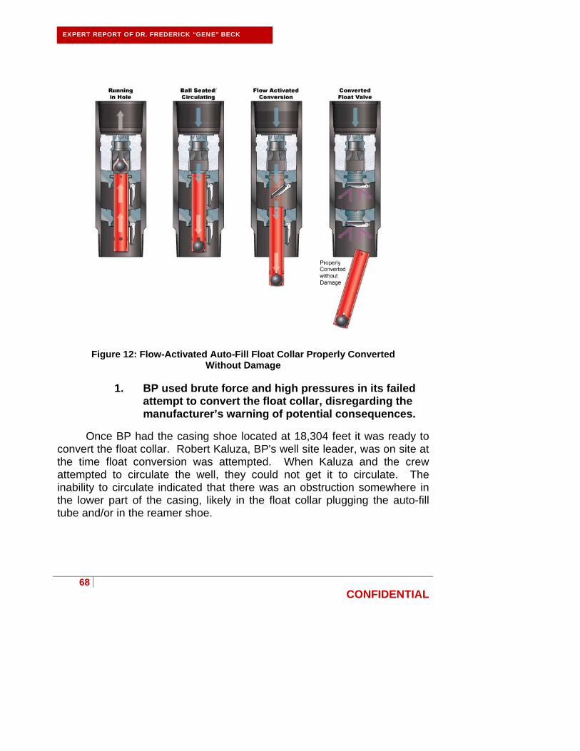
68
CONFIDENTIAL
EXPERT REPORT OF DR. FREDERICK “GENE” BECK
Figure 12: Flow-Activated Auto-Fill Float Collar Properly Converted Without Damage
1. BP used brute force and high pressures in its failed
attempt to convert the float collar, disregarding the manufacturer’s warning of potential consequences.
Once BP had the casing shoe located at 18,304 feet it was ready to convert the float collar. Robert Kaluza, BP's well site leader, was on site at the time float conversion was attempted. When Kaluza and the crew attempted to circulate the well, they could not get it to circulate. The inability to circulate indicated that there was an obstruction somewhere in the lower part of the casing, likely in the float collar plugging the auto-fill tube and/or in the reamer shoe.

69
CONFIDENTIAL
EXPERT REPORT OF DR. FREDERICK “GENE” BECK
Figure 13: Obstructions Prevent Circulation

70
CONFIDENTIAL
EXPERT REPORT OF DR. FREDERICK “GENE” BECK
Mr. Kaluza and his team established circulation after nine attempts, continually raising the pump pressure far above designed specifications. The nine attempts to establish circulation were as follows:
1. Pressure up to 1,800 psi at 1 barrel per minute (bpm), no circulation established, bleed off pressure.
2. Pressure up to 1,900 psi at 1 bpm, no circulation established,
bleed off pressure. 3. Pressure up to 2,000 at 1 bpm, pressure held at 1,950 psi, no
circulation established, bleed off pressure. 4. Pressure up to 2,000 at 1 bpm, pressure held at 1,940 psi, no
circulation established, bleed off pressure. 5. Pressure up to 2,000 at 1 bpm, held pressure for ten minutes,
no circulation established, bleed off pressure. 6. Pressure up to 2,000 at 2 bpm, no circulation established, bleed
off pressure. 7. Pressure up to 2,250 at 1 bpm, no circulation established, bleed
off pressure. 8. Pressure up to 2,500 at 1 bpm, pressure held at 2,450 psi, no
circulation established, bleed off pressure. 9. Pressure up to 2,750 at 1 bpm and held for two minutes,
pressure up to 3,000 psi and held for two minutes, pressure up to 3,142 psi when the pressure finally drops and mud starts to circulate.99
During these attempts to establish circulation and convert the float
collar, the rig crew sought advice from onshore. BP’s Morel called Bryan Clawson of Weatherford to ask how much pressure could be applied to the
99 Depo. Ex. 1425 at BP-HZN-MBI00191720-726.

71
CONFIDENTIAL
EXPERT REPORT OF DR. FREDERICK “GENE” BECK
float collar.100 Clawson checked with Weatherford engineering and told Morel that BP could pressure up as high as 6,800 psi; however, Clawson also stated that the ball would pass through the auto-fill tube without converting the floats at 1,300 psi.101 Despite this warning, BP continued its risky brute force attempts to convert the float collar.
The Weatherford specifications state that to convert the float collar, flow must be established at 5-8 barrels per minute.102 As seen in the following figure and as described in BP’s daily logs, the flow rate during the attempted conversion never exceeded 2 bpm.103
100 CCR at 89; see also evidence cited at CCR at 89 e.g., Tr. of USCG/MMS Investigation, 7/22/2010 (J. Guide Testimony) at 197:1-25. 101 CCR at 89; see also evidence cited at CCR at 89 e.g., Tr. of USCG/MMS Investigation, 7/22/2010 (J. Guide Testimony) at 197:1-25; BP-HZN-MBI21330. 102 Depo. Ex. 2562 at WFT-MDL-0020469-476. 103 Depo. Ex. 1425 at BP-HZN-MBI00191722-23.

72
CONFIDENTIAL
EXPERT REPORT OF DR. FREDERICK “GENE” BECK
Figure 14: Nine Attempts Prior to Assumed Conversion of Float Collar on April 19,
2010 (Figure 13 from Transocean Report, Alteration Added)104
Disregarding Weatherford’s advice that the ball could be blown out of the tube at 1,300 psi, BP pressured up the well and established flow at 3,142 psi, which could have ejected the ball or otherwise damaged the float collar, casing, or reamer shoe.105 At the time, although BP’s Kaluza was worried that they had blown something up, instead of stopping to determine what could have been blown up he and his team pushed forward.106 Kaluza confirmed BP’s disregard for Weatherford’s advice in his interview with the BP investigation team, stating “To shear out we had to gradually ramp up - I called town as I wasn't sure how high to go (Weatherford said 7
104 Transocean Report, Vol. I at 52.
105 Id. 106 Tr. of USCG/MMS Investigation, 8/24/2010 (N. Chaisson Testimony) at 432:19-24.
Deleted: R. Kaluza Testimony
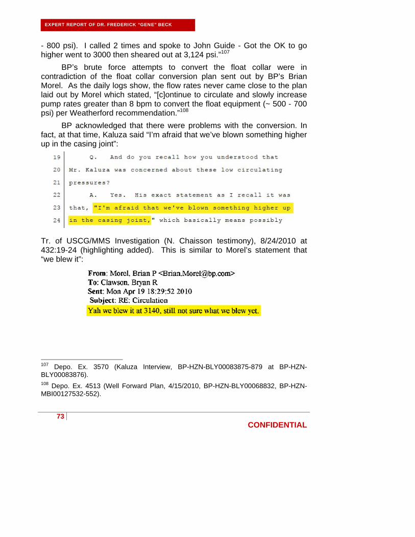
73
CONFIDENTIAL
EXPERT REPORT OF DR. FREDERICK “GENE” BECK
- 800 psi). I called 2 times and spoke to John Guide - Got the OK to go higher went to 3000 then sheared out at 3,124 psi.”107
BP’s brute force attempts to convert the float collar were in contradiction of the float collar conversion plan sent out by BP’s Brian Morel. As the daily logs show, the flow rates never came close to the plan laid out by Morel which stated, “[c]ontinue to circulate and slowly increase pump rates greater than 8 bpm to convert the float equipment (~ 500 - 700 psi) per Weatherford recommendation.”108
BP acknowledged that there were problems with the conversion. In fact, at that time, Kaluza said “I’m afraid that we’ve blown something higher up in the casing joint”:
Tr. of USCG/MMS Investigation (N. Chaisson testimony), 8/24/2010 at 432:19-24 (highlighting added). This is similar to Morel’s statement that “we blew it”:
107 Depo. Ex. 3570 (Kaluza Interview, BP-HZN-BLY00083875-879 at BP-HZN-BLY00083876). 108 Depo. Ex. 4513 (Well Forward Plan, 4/15/2010, BP-HZN-BLY00068832, BP-HZN-MBI00127532-552).
74
CONFIDENTIAL
EXPERT REPORT OF DR. FREDERICK “GENE” BECK
Depo. Ex. 2584 at BP-HZN-MBI 00129068 (highlighting added). A prudent operator would have taken steps at that time to evaluate the condition of the float collar.
2. BP ignored that it likely damaged the float collar with the high pressures it applied.
Once BP’s team established circulation they assumed that the float collar had been converted even though they never circulated at a rate higher than 4.3 barrels per minute, which was too low to bring about conversion.109 Specifically, observed flow rates and pressures never exceeded 4.3 bpm and 375 psi, respectively.110
The pressure predicted by Weatherford for flow through an unconverted float collar at 4.3 BPM is 330 psi. By my calculations, 375 psi is consistent with the pressure that would be required to circulate the entire casing through either a converted float collar or through a float collar with the flow tube still in place but with the ball and ball seat blown out. In hindsight, the observed pressure, in conjunction with the fact that the check valves did not prevent the blowout, suggests that the ball seat had been blown out of the float collar, leaving the tube in place with the check valves locked open. Transocean’s tests show the ball being blown out at 1,477 psi with the auto-fill tube held in place, which could have been facilitated by debris in and around the auto-fill tube.111 It is also possible that BP damaged the float collar in some other manner that prevented the float collar from serving as a barrier to the shoe track while exhibiting the observed flow-pressure profile.
BP had knowledge that the pressures placed on the well were likely to damage the float collar and should have proceeded with all caution on subsequent well operations. Instead BP ignored the likelihood that the float collar was damaged and proceeded to cement the casing and conduct further operations.
109 Depo. Ex. 1425 at BP-HZN-MBI00191720-726
110 Bly Report at 70; see also note 99, supra.
111 Transocean Report, Vol. II, App. C (Stress Engineering Report) at 14.

75
CONFIDENTIAL
EXPERT REPORT OF DR. FREDERICK “GENE” BECK
E. BP created wellbore conditions that were conducive to plugging and damaging the casing, float collar, and/or shoe track.
During the installation of the production casing on the Macondo well, the drilling fluid sat static for over 45 minutes after the casing reached bottom. This is ample time for barite, or other debris such as lost circulation material, to settle in the shoe track across the flow tube and/or in the guide shoe, plugging either or both and locking in the auto-fill tube. Circulation was not established in the well until after the ninth attempt (see Fig. 14 above) when a pump pressure of 3,142 psi was reached, at which point there was an instantaneous drop in pump pressure, after which return flow was noted. Tests conducted by Transocean determined that the pressure that BP placed on the well (3,142 psi) was sufficient to have damaged the auto-fill mechanism in the float collar,112 the guide shoe, and/or perhaps the shoe track itself. BP was aware that the float collar was potentially damaged113 and should have maintained caution throughout all subsequent well operations until testing confirmed that a barrier was placed successfully in the well.
1. Transocean confirmed Weatherford’s warning about ejecting the float collar ball.
Transocean retained Stress Engineering Inc. to test the Weatherford M45AP float collar. One test conducted by Stress Engineering evaluated the pressure required to push the ball through the seat by testing two auto–fill tubes and balls. One seat failed at 1,477 psi and the other seat failed at 1,840 psi.114 This supports Weatherford’s recommended practice of a maximum pressure of 1,300 psi prior to conversion, which BP ignored, and shows that blowing the ball out of the auto-fill tube without conversion was possible as indicated and advised by Mr. Clawson of Weatherford prior to
112 Transocean Report, Vol. II, App. C (Stress Engineering Report) at 14.
113 CCR at 89; see also evidence cited at CCR at 89, e.g., BP-HZN-MBI 129068; Tr. of USCG/MMS Investigation, 8/24/2010 (N. Chaisson testimony) at 432:19-24; Tr. of Telephone Interview of Jesse Marc Gagliano, 6/11/2010 at 64-65.
114 Transocean Report, Vol. II, App. C (Stress Engineering Report) at 14.

76
CONFIDENTIAL
EXPERT REPORT OF DR. FREDERICK “GENE” BECK
the blowout, particularly with barite or other debris holding the auto-fill tube in place.115 The ball seat failure is illustrated in Figure 15:
115 Transocean Report, Vol. II, App. C (Stress Engineering Report) at 14.
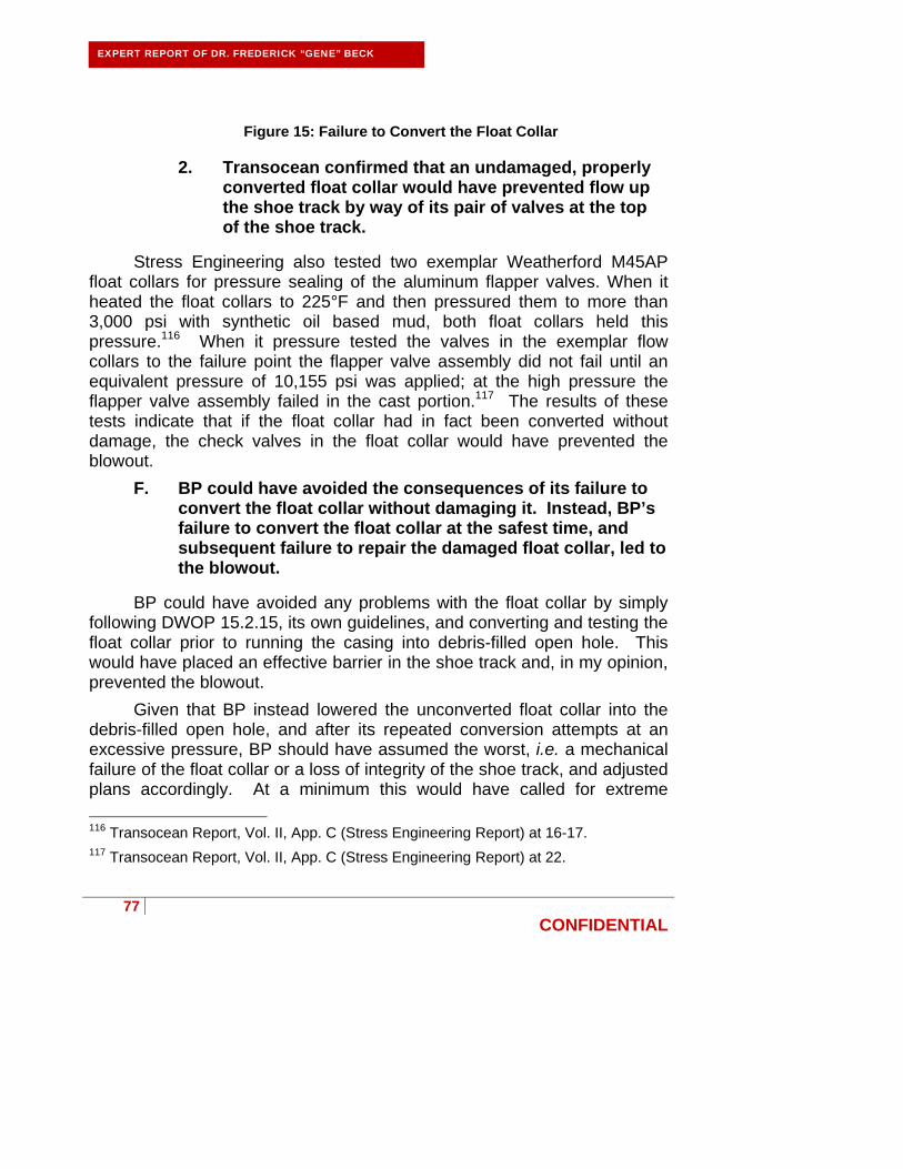
77
CONFIDENTIAL
EXPERT REPORT OF DR. FREDERICK “GENE” BECK
Figure 15: Failure to Convert the Float Collar
2. Transocean confirmed that an undamaged, properly converted float collar would have prevented flow up the shoe track by way of its pair of valves at the top of the shoe track.
Stress Engineering also tested two exemplar Weatherford M45AP float collars for pressure sealing of the aluminum flapper valves. When it heated the float collars to 225°F and then pressured them to more than 3,000 psi with synthetic oil based mud, both float collars held this pressure.116 When it pressure tested the valves in the exemplar flow collars to the failure point the flapper valve assembly did not fail until an equivalent pressure of 10,155 psi was applied; at the high pressure the flapper valve assembly failed in the cast portion.117 The results of these tests indicate that if the float collar had in fact been converted without damage, the check valves in the float collar would have prevented the blowout.
F. BP could have avoided the consequences of its failure to convert the float collar without damaging it. Instead, BP’s failure to convert the float collar at the safest time, and subsequent failure to repair the damaged float collar, led to the blowout.
BP could have avoided any problems with the float collar by simply following DWOP 15.2.15, its own guidelines, and converting and testing the float collar prior to running the casing into debris-filled open hole. This would have placed an effective barrier in the shoe track and, in my opinion, prevented the blowout.
Given that BP instead lowered the unconverted float collar into the debris-filled open hole, and after its repeated conversion attempts at an excessive pressure, BP should have assumed the worst, i.e. a mechanical failure of the float collar or a loss of integrity of the shoe track, and adjusted plans accordingly. At a minimum this would have called for extreme
116 Transocean Report, Vol. II, App. C (Stress Engineering Report) at 16-17. 117 Transocean Report, Vol. II, App. C (Stress Engineering Report) at 22.

78
CONFIDENTIAL
EXPERT REPORT OF DR. FREDERICK “GENE” BECK
caution and suspicion when conducting integrity tests on the well following casing installation and cementing operations. A more conservative approach would have been to stop operations and install a replacement check valve in the casing prior to cementing the casing in place. This would have substantially lowered the risk of cementing a potentially damaged shoe track.
Instead, BP’s failure to convert the float collar without damaging it removed a barrier to hydrocarbon flow from the well. If BP had properly converted the float collar without damaging it, hydrocarbons would have been blocked from flowing up the shoe track and the kick that led to the blowout would have been prevented. In my opinion the failure to convert the float collar without damaging it was a root cause of the blowout.
G. BP unreasonably chose not to circulate bottoms up or to adequately condition the wellbore for cement placement.
After establishing circulation, BP proceeded with plans to cement the casing in place. Prior to pumping cement, BP circulated a total of 346 barrels of mud through the well, a small fraction of what was required to move drilling mud from the bottom of the well to the surface (the “bottoms up”). Although there were no mud losses during this circulation period that would have required stopping the circulation early, BP chose to stop pumping early and proceeded directly to the primary cement job, foregoing the widely recognized good practice of circulating bottoms up prior to cementing. In this expert’s experience, not circulating bottoms up is an extraordinary decision. The only acceptable event that would preclude a full circulation of the wellbore prior to cementing is a loss of circulation.
Circulating the full annular volume prior to cementing serves several purposes, not the least of which is establishing that there is not a kick in the well following the long period required to run the casing, particularly where as here the well had previously shown that hydrocarbons were seeping into the wellbore during logging operations.118 This fact alone dictated that the well should have been fully circulated prior to cementing.
Circulating the well prior to cementing also serves to fully condition (i.e. clean) both the drilling mud and the wellbore to facilitate cement
118 BP-HZN-2179MDL3541-45 at BP-HZN-2179MDL3543; Depo. Ex. 3188 at BP-HZN-BLY0061515.

79
CONFIDENTIAL
EXPERT REPORT OF DR. FREDERICK “GENE” BECK
placement. Drilling fluid properties can be adjusted and confirmed, the filter cake along the wellbore wall can be eroded, and the debris in the well can be removed. Each of these processes improves the likelihood of achieving a satisfactory cement job.
H. BP unreasonably failed to confirm the function of the check valves in the float collar.
Once cement is pumped and the pumping pressure is removed from the casing, if the column of cement in the annulus creates sufficient backpressure to overcome the resistance of the wiper plug, the cement will be hydraulically forced back into the shoe track and up the casing. If a check valve in the float collar (or float shoe, if run) functions, the valve will prevent the cement from flowing back into the casing. If the float valve does not function properly, the cement will continue to flow up into the casing, forcing fluid to be displaced out of the casing at the rig surface. If unchecked, this backflow of cement into the casing will continue until the fluid pressures inside the casing balance the fluid pressures in the annulus, and the cement job will be compromised since the desired top of cement will be far lower in the annulus than desired.
The standard method for checking floats is to bleed the pressure off of the casing after the “plug has bumped,” i.e. the cement has been placed, all the while monitoring the volume and rate of fluid flowing back out of the well. The volume expected from this process is reasonably predictable, and if the volume returned from the well exceeds the predicted volume, it is assumed that the check valves are not functioning. If this happens, the standard response is to once again pump mud into the casing, re-bump the plug to a pressure matching the backpressure created by the annular cement, then close a valve at the surface. This surface valve then acts as a check valve, preventing the cement from flowing back into the casing. The valve is usually left closed for an extended period of time (24 hours or more) to allow the cement sufficient time to cure.
The conditions existing in the Macondo well after the cement job were far from ideal for identifying whether or not the check valves were functional, and the standard technique for “checking the floats” was not going to identify whether or not the floats were functioning correctly. BP’s cement design for the Macondo well resulted in minimal, if any, backpressure created by the annular cement, with estimates generally well

80
CONFIDENTIAL
EXPERT REPORT OF DR. FREDERICK “GENE” BECK
less than 100 psi.119 The prudent response, in light of the difficulties in converting the float collar and the very real chance that the float collar had been damaged, would have been to assume that the float had failed and shut the well in for 24-48 hours and allow the cement time to cure.
It is evident that the float valves were not functional (i.e. had not closed properly). A functioning check valve in the float collar would have prevented the blowout by preventing the cement in the shoe track and any hydrocarbons below the shoe track from flowing up the shoe track through the float collar and into the casing. While a float valve may not be considered by some to be a reliable long term barrier to hydrocarbon flow up the casing, a float valve is a reliable temporary barrier (particularly to fluids like cement and mud) and during the time frame of running casing, pumping, and waiting on cement, a float valve is routinely relied upon to perform as a barrier. The Transocean testing of the exemplar Weatherford M45AP float collars, as described above, proves that the check valves were capable of containing pressure and would be a reliable barrier following the placement of the cement. Transocean’s testing showed that the float collar valves (when properly closed) held to pressures far exceeding those experienced by the Macondo well. The maximum differential pressure the valves would have seen if closed was the 2,350 psi differential pressure created by the negative pressure test discussed below.
I. BP jeopardized the shoe track cement’s ability to form a barrier to hydrocarbon flow.
1. BP indicated it was pleased with Halliburton’s cement work.
While BP has submitted anecdotal evidence that they were displeased with the performance of Halliburton personnel, including Jesse Gagliano, emails and other evidence reflect the opposite.120 Immediately after pumping the cement job on April 20, 2010, BP representatives sent emails noting the successful cement job executed by Halliburton. For example, BP’s Brian Morel sent the following email:
119 Depo. Ex. 3190 at BP-HZN-2179MDL00321875.
120 Depo. Ex. 283; E. Cunningham Depo., 3/24/2011 at 406:17-24.

81
CONFIDENTIAL
EXPERT REPORT OF DR. FREDERICK “GENE” BECK
Depo. Ex. 282 (highlighting added). BP’s Brian Morel sent a similar email later in the day on April 20, 2010, writing that Halliburton had done a “great job” in executing the cement program.
Depo. Ex. 283 (highlighting added).
2. BP provided inadequate centralization and allocated insufficient time for waiting-on-cement, thereby jeopardizing the cement job.
As discussed above, BP ignored Halliburton’s recommendations on centralization, and instead used an inadequate number of centralizers that likely resulted in channeling, as Halliburton had warned BP with its OptiCem™ simulation results. Additionally, during drilling operations, a variety of factors in the well can affect the time it actually takes for cement to cure. A few of these factors include contamination of the cement in the casing string and/or the annulus and movement of the cement after placement. Accordingly, it is prudent and common to allow at least 24 hours of wait-on-cement time to ensure that the cement is properly set.
In regard to the Macondo well, BP knew that cement was pumped into the well under non-ideal conditions and that there was a question as to whether the float equipment had been successfully converted without damage. There was also a high risk of contamination as well as channeling (e.g., due to BP’s failure to do a full bottoms up circulation to clean the well prior to pumping the cement down the well, BP’s failure to
82
CONFIDENTIAL
EXPERT REPORT OF DR. FREDERICK “GENE” BECK
protect against swapping with the rat hole mud, BP’s inadequate centralization,121 BP’s requiring a low displacement rate,122 and BP’s ignoring the high gas flow potential that Halliburton reported from the OptiCem™ simulations). Fully aware that these factors justified increased wait-on-cement time, BP unreasonably reduced the wait-on-cement time to 10 hours and rushed to conduct the positive pressure test. BP further proceeded to conduct the negative pressure test discussed below only 16 hours after cement placement, testing the cement through a float collar that BP knew was possibly damaged and unconverted (and, in fact, was not converted without damage) before ensuring that the cement had a chance to fully set and cure. BP’s sole objective for reducing the wait-on-cement time was to save time and money.123 BP should have waited on cement a minimum of 24 hours.
3. Halliburton did not cause any failure of the shoe track cement job.
Indications are that the annulus cement performed as expected (i.e. that the nitrified cement set up in the annulus), so that the shoe track cement should have performed equally as well. Indeed, the JIT report concludes that intact, set up cement was present in the annulus during intervention operations conducted on Macondo following relief well operations.124 Both the JIT Report and the Chief Counsel’s Report point out that hydrocarbons were not present in the annular space outside the long string when annular fluids were examined during the relief effort, 121 Depo. Ex. 2579.
122 CCR at 80, n. 75; BP-HZN-MBI00127532-552 at 537-539.
123 Depo. Ex. 604; see e.g., CCR at 93, 145, and 147; see also evidence cited at CCR at 93 and 145, e.g., BP-HZN-MBI00139592; BP-HZN-MBI00136948.
124 JIT Report at 60 (concluding that the cement in annulus did not fail); id. at 62-64, 73 (stating that forensic evidence collected during the well intervention operations, including (1) a successful positive pressure test of the 9-7/8 inch production casing annulus, (2) absence of free gas in the annulus below the BOP to 9,318 feet measured depth, (3) no u-tube flow occurred from the casing to annulus, (4) presence of the original 13.8-14.0 ppg mud between the 16 inch intermediate casing and 9-7/8 inch production casing, and (5) the wellhead seal assembly and hanger remained intact and showed no sign of erosion from annular flow, shows that “the nitrified cement slurry used in the annulus likely did not fail.”) (citing to TRN-USCG_MMS-00043342, TRN-USCG_MMS-00043388, TRN-USCG_MMS-00043449).
Deleted: Depo. Ex. 2579;
Deleted: 116

83
CONFIDENTIAL
EXPERT REPORT OF DR. FREDERICK “GENE” BECK
reflecting that the annular cement worked as intended.125 These reports specifically note that the foamed cement pumped by Halliburton into the annular space outside of the long string production casing set up, performed as intended, and formed a barrier to upward annular flow. The shoe track cement was identical to the cement pumped into the annulus but for the fact that the shoe track cement was not nitrified, and thus should similarly have performed as expected.
The generally stated and accepted view to date is that the hydrocarbon flow during the blowout flowed up the shoe track (i.e. through the unconverted and damaged float collar and through the interior of the long string production casing to the surface). For this flow path, all indications are that BP’s actions compromised isolation by way of the shoe track cement, so as to enable the flow of hydrocarbons up the shoe track through the unconverted and damaged float collar. Thus, BP alone is at fault for any failure of its shoe track cement isolation.
First, BP’s failure to guard against channeling likely contributed to the failure of shoe track cement isolation by allowing in hydrocarbon flow from the inadequately centralized annulus and potential swapping with the rathole mud.
Second, BP’s failure to convert the float equipment without damaging
it allowed u-tubing to occur, which consequently would have extended the time required for the shoe track cement to set. The primary reason for using a float collar in cementing operations is the fact that cement needs to be in a static state as it sets. A float collar allows cement to flow through and then traps it in place. A damaged and unconverted float collar, like the damaged and unconverted float collar in the Macondo well, permits movement of the cement—u-tubing—that can compromise the cement in the shoe track. Even seemingly small displacements of the cement during the setting process can affect how, when, or if the cement sets. Because moving cement will not set, u-tubing could have delayed the setting of the shoe track cement such that it was still somewhat liquid when BP began the negative pressure test discussed below. If that was the case, when BP 125 See note 124, supra; JIT Report at 63 and 73 (concluding that free gas was absent in the annulus based on the examination of the characteristics of fluid in the annulus between the mud line and 9,318 feet measured depth); CCR at 43 (stating that upon intercepting the production casing midway down the well at 9,150 feet, the sampling of the annular fluids shows that hydrocarbon likely had not flowed through the annulus).

84
CONFIDENTIAL
EXPERT REPORT OF DR. FREDERICK “GENE” BECK
began displacing the well after the negative pressure test, any unset shoe track cement would have been free to flow up the well during the initiation of the blowout.
Third, BP may have damaged the shoe track during its failed attempt
to convert the float equipment by applying excessively high pressures to the well. BP personnel were aware that something “blew out” during the failed float conversion,126 and BP engineers were concerned that the long string production casing could buckle when it was being lowered into the well.127 In the days leading up to installation of the long string production casing in the well, BP’s Brian Morel requested that Halliburton personnel perform a buckling analysis on the long string production casing, and that analysis indicated that buckling from the float collar to the bottom of the shoe track was possible under the conditions in which the casing was actually run into the hole.128 It is possible that the entire shoe track separated from the float collar, meaning that there was, in essence, no shoe track at all. What “blew” down hole could have been the shoe track separating from the remainder of the long string production casing just below the float collar assembly. This is illustrated in Figure 16 below:
126 Depo. Ex. 2584 at BP-HZN-MBI00129068.
127 Depo. Ex. 3199 (highlighting added).
128 Depo. Ex. 4515.
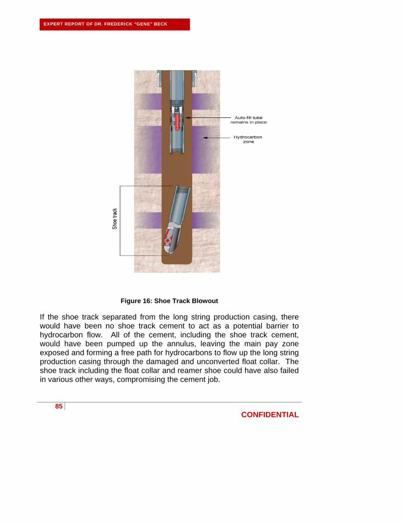
85
CONFIDENTIAL
EXPERT REPORT OF DR. FREDERICK “GENE” BECK
Figure 16: Shoe Track Blowout If the shoe track separated from the long string production casing, there would have been no shoe track cement to act as a potential barrier to hydrocarbon flow. All of the cement, including the shoe track cement, would have been pumped up the annulus, leaving the main pay zone exposed and forming a free path for hydrocarbons to flow up the long string production casing through the damaged and unconverted float collar. The shoe track including the float collar and reamer shoe could have also failed in various other ways, compromising the cement job.

86
CONFIDENTIAL
EXPERT REPORT OF DR. FREDERICK “GENE” BECK
Fourth, BP waited only 16 hours before performing the negative pressure test. It is possible that, because of the u-tubing and/or contamination, the shoe track cement had not yet set and flowed uphole through the damaged and unconverted float collar when the well was underbalanced as part of the negative pressure test.
Also, at least one of the cement plugs appears to have landed early.129 This suggests that oil-based mud may have been trapped below the upper cement plug, contaminating the shoe track cement. Contamination by oil-based mud, as shown Figure 17 below, could have extended the setting time of the cement.
129 Depo. Ex. 4502 at BP-HZN-CEC020233; CCR at 93; see also evidence cited at CCR at 93, e.g., BP-HZN-MBI0021305.
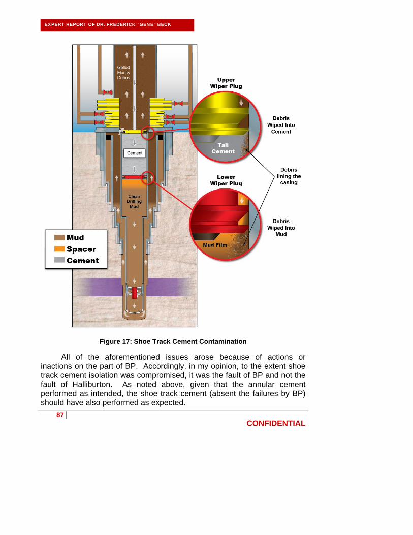
87
CONFIDENTIAL
EXPERT REPORT OF DR. FREDERICK “GENE” BECK
Figure 17: Shoe Track Cement Contamination
All of the aforementioned issues arose because of actions or inactions on the part of BP. Accordingly, in my opinion, to the extent shoe track cement isolation was compromised, it was the fault of BP and not the fault of Halliburton. As noted above, given that the annular cement performed as intended, the shoe track cement (absent the failures by BP) should have also performed as expected.
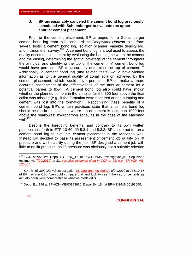
88
CONFIDENTIAL
EXPERT REPORT OF DR. FREDERICK “GENE” BECK
J. BP unreasonably canceled the cement bond log previously scheduled with Schlumberger to evaluate the upper annular cement placement.
Prior to the cement placement, BP arranged for a Schlumberger cement bond log team to be onboard the Deepwater Horizon to perform several tests: a cement bond log, isolation scanner, variable density log, and inclinometer survey.130 A cement bond log is a tool used to assess the quality of cement placement by evaluating the bonding between the cement and the casing, determining the spatial coverage of the cement throughout the annulus, and identifying the top of the cement. A cement bond log would have permitted BP to accurately determine the top of cement.131 Additionally, a cement bond log (and related tests) would have yielded information as to the general quality of zonal isolation achieved by the cement placement, which would have permitted BP to make a more accurate assessment of the effectiveness of the annular cement as a potential barrier to flow. A cement bond log also could have shown whether the planned cement in the annulus for the 300 feet above the float collar was missing (e.g., if the formation were fractured during pumping and cement was lost into the formation). Recognizing these benefits of a cement bond log, BP’s written practices state that a cement bond log should be run in all instances where top of cement is less than 1000 feet above the shallowest hydrocarbon zone, as in the case of the Macondo well.132
Despite the foregoing benefits, and contrary to its own written practices set forth in ETP 10-60, §§ 5.3.1 and 5.3.3, BP chose not to run a cement bond log to evaluate cement placement in the Macondo well. Instead BP decided to base its assessment of cement job quality on lift pressure and well stability during the job. BP designed a cement job with little to no lift pressure, so lift pressure was obviously not a suitable criterion
130 CCR at 95; see Depo. Ex. 526 (Tr. of USCG/MMS Investigation (R. Sepulvado testimony), 7/20/2010) at 21; see also evidence cited in CCR at 95, e.g., BP-HZN-MBI 126867.
131 See Tr. of USCG/MMS Investigation (J. Gagliano testimony), 8/24/2010 at 276:10-15 (if BP had run CBL “we could compare that and look to see if the cap of cements as actually seen were comparable to what we modeled.”).
132 Depo. Ex. 184 at BP-HZN-MBI00193660; Depo. Ex. 184 at BP-HZN-MBI00193668.

89
CONFIDENTIAL
EXPERT REPORT OF DR. FREDERICK “GENE” BECK
for cement evaluation. Moreover, BP’s former vice president of drilling recognizes that it is not uncommon to have a failed primary cement placement in deepwater drilling and that “you would probably be safest to assume that there is generally a problem or a likelihood of lack of zonal isolation.”133 Obtaining a cement bond log on the Macondo well would have at least identified the top of cement and the possible need for remedial cementing operations. Successfully placing cement in the annular space to achieve zonal isolation is one of the most unpredictable tasks faced during the drilling of any well, even more so on a well as unstable as was the Macondo. The need to evaluate the effectiveness of the cement placement is obvious. BP chose to cancel the cement bond log to save time and money, once again placing time to production ahead of safety.
K. BP failed to provide a safe temporary abandonment plan.
In my opinion, the tasks facing BP for abandonment were clear. First, BP needed to set a lock-down sleeve on the casing hanger seal assembly, which serves to anchor the casing firmly to the wellhead, and would guard against the casing hanger seal assembly becoming unseated during the negative pressure test or in the event that excessive pressure were to build in the annulus beneath the casing hangar. Second, BP needed to establish well integrity by conducting both positive and negative pressure tests on the well, clearly establishing primary isolation from the reservoir. Third, BP needed to set a cement plug inside the casing as a replacement barrier for the blowout preventer, prior to BP’s removing the drilling mud from the riser. BP could have shown appropriate further caution by taking the additional step, prior to setting the cement plug, of filling the well with heavy mud from the seafloor to the float collar, which would then allow the removal of the drilling fluid from the riser, without underbalancing the well. Either way, after the cement plug was set, its effectiveness as a barrier could be proven with what is essentially a second negative pressure test. At that point the blowout preventer could be safely removed from the well.
In planning the temporary abandonment, BP chose to merge and re-order the foregoing distinct operations (as well as eliminate some operations) in an effort to save rig time (and therefore substantial money). This is evidenced by the temporary abandonment procedure approved by the Minerals Management Service (now known as the Bureau of Ocean
133 K. Lacy Depo., 6/22/2011 at 522:5-16.
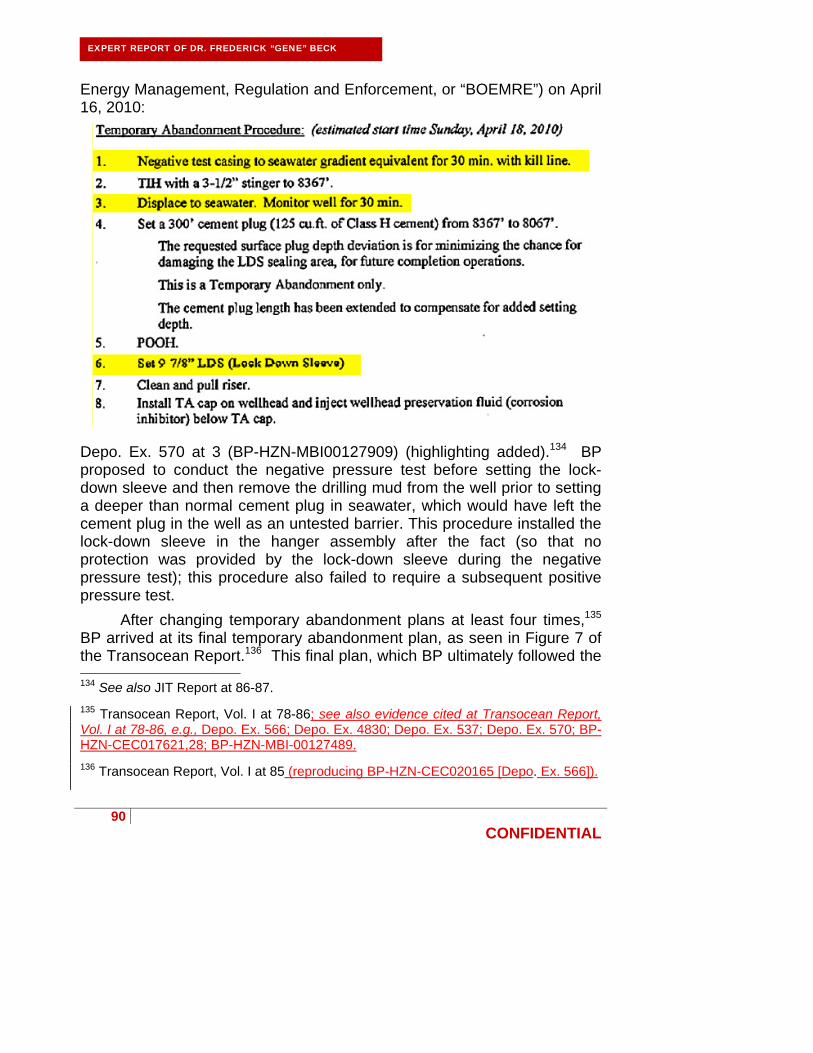
90
CONFIDENTIAL
EXPERT REPORT OF DR. FREDERICK “GENE” BECK
Energy Management, Regulation and Enforcement, or “BOEMRE”) on April 16, 2010:
Depo. Ex. 570 at 3 (BP-HZN-MBI00127909) (highlighting added).134 BP proposed to conduct the negative pressure test before setting the lock-down sleeve and then remove the drilling mud from the well prior to setting a deeper than normal cement plug in seawater, which would have left the cement plug in the well as an untested barrier. This procedure installed the lock-down sleeve in the hanger assembly after the fact (so that no protection was provided by the lock-down sleeve during the negative pressure test); this procedure also failed to require a subsequent positive pressure test.
After changing temporary abandonment plans at least four times,135 BP arrived at its final temporary abandonment plan, as seen in Figure 7 of the Transocean Report.136 This final plan, which BP ultimately followed the 134 See also JIT Report at 86-87.
135 Transocean Report, Vol. I at 78-86; see also evidence cited at Transocean Report, Vol. I at 78-86, e.g., Depo. Ex. 566; Depo. Ex. 4830; Depo. Ex. 537; Depo. Ex. 570; BP-HZN-CEC017621,28; BP-HZN-MBI-00127489.
136 Transocean Report, Vol. I at 85 (reproducing BP-HZN-CEC020165 [Depo. Ex. 566]).

91
CONFIDENTIAL
EXPERT REPORT OF DR. FREDERICK “GENE” BECK
day of the blowout, differed from the Minerals Management Service-approved plan set forth above in that the final plan called for beginning early on with the displacement to seawater, stopping in the midst of the displacement to conduct the negative pressure test, and then continuing with the displacement.
Depo. Ex. 566 (highlighting added). As discussed below, BP’s final planned temporary abandonment procedure was unsafe because it: (1) called for waiting until last to set the lockdown sleeve; (2) did not allow for the independent testing of two barriers along each potential flow path; and (3) created a risk of damaging the shoe track cement. The blowout occurred during step five of BP’s final planned temporary abandonment procedure.
1. BP took unnecessary risks by planning to set the lockdown sleeve last.
The lockdown sleeve locks the casing hanger to the well head housing, holding the casing in place and preventing upward movement of the casing that may otherwise occur. Such vertical movement would be detrimental because it could permit an influx of hydrocarbons from the annulus to the riser.

92
CONFIDENTIAL
EXPERT REPORT OF DR. FREDERICK “GENE” BECK
Setting a lockdown sleeve requires the operator to place about 100,000 lbs. of weight on the sleeve to lock it into place.137 BP sought to do this by hanging 3,000 feet of drill pipe below the mudline.138 In conjunction with this, BP decided to set the surface cement plug at this unusually deep depth—lower than 3,000 feet below the mudline. BP further decided to set the surface plug in seawater rather than mud (which was not necessary), which in turn led to the displacement of mud from about 3,000 feet below the mudline (8,367 feet below sea level) to above the blowout preventer, resulting in an significantly underbalanced well.
According to BP, BP decided to set the lockdown sleeve as the last step in the temporary abandonment procedure to supposedly guard against damaging it. In my opinion the risk associated with the casing hanger lifting off-seat during the negative pressure test far outweighs any risk associated with damaging the lock-down sleeve. If the casing hanger lifts off-seat during the negative pressure test, a kick and a severe well control incident is a likely outcome; if the lock-down sleeve is damaged during the completion, the risk is only in incremental cost to repair or replace the sleeve. Also, because BP set the cement plug 3,000 feet below the mudline, the well was exposed to a much higher degree of underbalance during the negative pressure test, as well as during the displacement to seawater, the consequences of which were a greater chance of failing a barrier and inducing a kick. Because the potential cost to repair or replace a damaged lock-down sleeve is trivial in comparison to a potential well control event, basic risk assessment counseled that BP should have set the lock-down sleeve as a first step in the temporary abandonment process.
2. BP’s plan did not provide for two independently tested barriers along each of the potential flow paths.
Both safe drilling practices and BP’s written practices139 demand that two barriers be in place along any potential flow path to the seafloor and 137 Depo. Ex. 2775 at 1.
138 It is possible to place 100,000 lbs. of weight on the lockdown sleeve without a full 3,000 feet of space below the mudline. BP’s April 12 2010 plan called for use of heavyweight drill pipe collars which would have required less space. See Depo. Ex. 4830 at BP-HZN-CECO21268 (“5-1/2 inch 21.9 ppf x 5-1/2 inch HWDP x 6.5 inch collars should be used”).
139 Depo. Ex. 6121 at BP-HZN-BLY00034588.
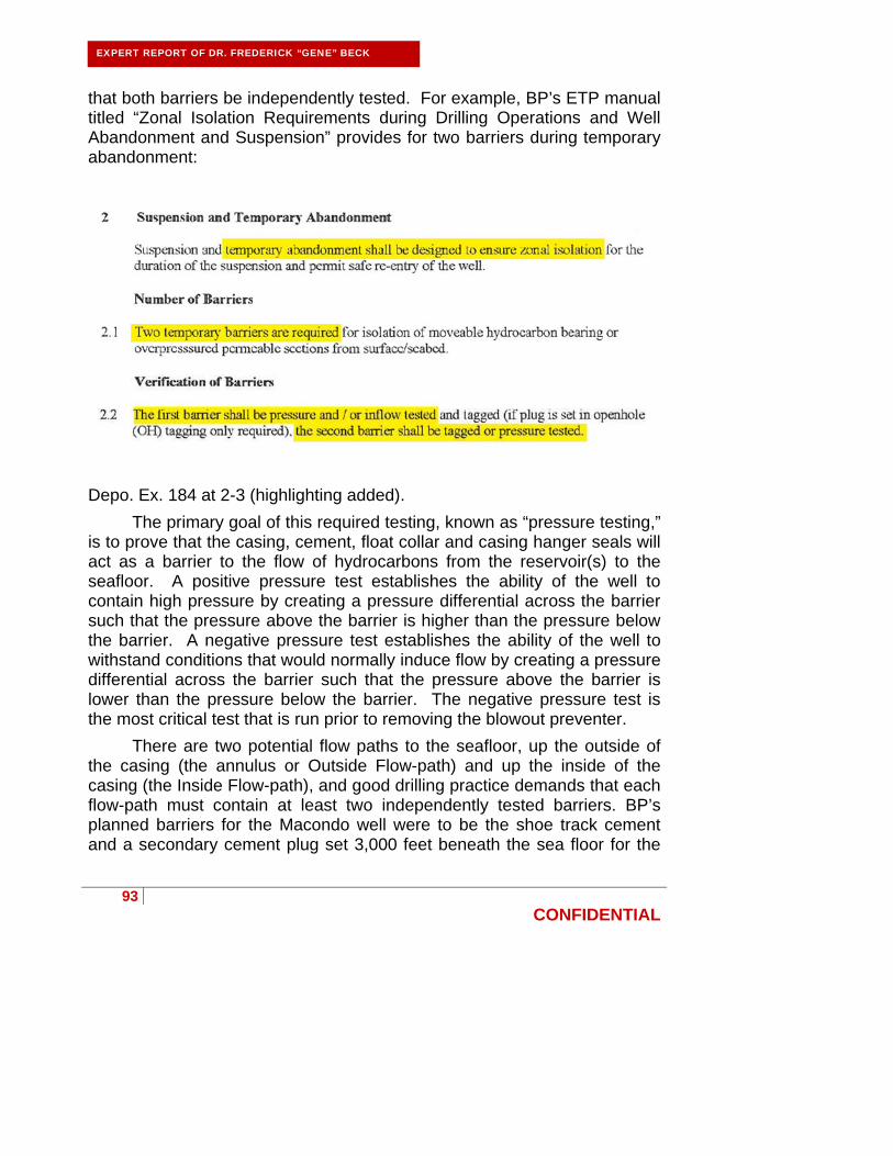
93
CONFIDENTIAL
EXPERT REPORT OF DR. FREDERICK “GENE” BECK
that both barriers be independently tested. For example, BP’s ETP manual titled “Zonal Isolation Requirements during Drilling Operations and Well Abandonment and Suspension” provides for two barriers during temporary abandonment:
Depo. Ex. 184 at 2-3 (highlighting added).
The primary goal of this required testing, known as “pressure testing,” is to prove that the casing, cement, float collar and casing hanger seals will act as a barrier to the flow of hydrocarbons from the reservoir(s) to the seafloor. A positive pressure test establishes the ability of the well to contain high pressure by creating a pressure differential across the barrier such that the pressure above the barrier is higher than the pressure below the barrier. A negative pressure test establishes the ability of the well to withstand conditions that would normally induce flow by creating a pressure differential across the barrier such that the pressure above the barrier is lower than the pressure below the barrier. The negative pressure test is the most critical test that is run prior to removing the blowout preventer.
There are two potential flow paths to the seafloor, up the outside of the casing (the annulus or Outside Flow-path) and up the inside of the casing (the Inside Flow-path), and good drilling practice demands that each flow-path must contain at least two independently tested barriers. BP’s planned barriers for the Macondo well were to be the shoe track cement and a secondary cement plug set 3,000 feet beneath the sea floor for the

94
CONFIDENTIAL
EXPERT REPORT OF DR. FREDERICK “GENE” BECK
Inside Flow-path, and the annular cement and casing hanger seals for the Outside Flow-path.
With BP’s well design and temporary abandonment procedure, BP did not provide for two independently tested barriers along each potential flow path. BP did not independently test the integrity of the planned annular cement barrier for the Inside Flow-path with its positive pressure test or its negative pressure test because both tests only tested the casing hanger seal assembly. The seal assembly isolated the cement sheath against the pressure tests; therefore the cement sheath on the outside of the casing was not a tested barrier. As discussed above, this is a consequence of the long string casing design. A liner/tie-back installation would have allowed for at least one additional independently tested barrier to be in place in the well at abandonment.
BP likewise did not independently confirm the integrity of the planned shoe track cement barrier for the Inside Flow-path with either its positive pressure test or its negative pressure test. In the positive pressure test, the top wiper plug was still in place following the cement placement. As a result, the positive pressure test did not independently test the integrity of the shoe track. The negative pressure test also did not independently confirm the integrity of the shoe track cement, as the negative pressure test tests the float collar and shoe track cement together. A functioning float collar isolates the shoe track cement from the pressure differential, only testing the float collar and leaving the shoe track cement untested. BP, to have a second independently tested barrier in place prior to underbalancing the well, should have planned to place the upper cement plug after confirming a successful negative pressure test of the float collar and shoe track cement combination. BP could have then independently tested the upper cement plug, providing two independently tested barriers in the Inside Flow-path during abandonment.
BP’s failure to design and plan for two independently tested barriers along each flow path during abandonment again illustrates BP’s willingness to assume unnecessary risks to save time and money.
Worse yet, BP ignored the failed negative pressure test, which clearly indicated that all of the barriers for one of the potential flow paths had failed. Given the generally accepted view to date that the flow path was the Inside Flow-path, the failed negative pressure test is conclusive evidence that the float collar barrier and the shoe track barrier had both failed. As

95
CONFIDENTIAL
EXPERT REPORT OF DR. FREDERICK “GENE” BECK
noted elsewhere, BP’s recklessness in disregarding the failed negative pressure test caused the blowout.
3. BP risked damaging the shoe track cement by performing the positive and negative pressure tests shortly after pumping the cement.
BP conducted the positive pressure test and negative pressure test just 10 hours and 42 minutes after the plug was bumped and 16 hours after the plug was bumped, respectively.140 This short time frame between bumping the plug and conducting the pressure tests subjected the the cement to damage by potentially moving the cement and placing pressure on the well prior to the cement gaining sufficient strength, thereby risking breaking the bond between the cement sheath and the casing and/or extending the cement set time by movement.
L. In performing the negative pressure test, BP and Transocean recklessly attributed the increase in pressure on the drill pipe to the so-called “bladder effect.”
BP’s negative pressure test sequence is well documented in BP’s Bly Report, the Chief Counsel’s Report, and the Transocean Report. The results are shown in Figure 20 from the Transocean Report, which is partially reproduced below.141
140 Depo. Ex. 604; see e.g., CCR at 93, 145, and 147.
141 Transocean Report, Vol. I at 100. Deleted: 44

96
CONFIDENTIAL
EXPERT REPORT OF DR. FREDERICK “GENE” BECK
Figure 18: Overview of Events during the Negative Pressure Test from 5:34-8:02 p.m.142
The negative pressure test was designed to achieve approximately 2,350 psi of differential pressure on the wellbore. Interpretation of the negative pressure test can be reduced to a single simple observation: Because the test was set up with the kill line and the drill pipe full of seawater and in pressure communication, once the test starts, the pressure at the surface of each component must be equal and must be zero. Any other combination of pressures indicates a problem and requires further investigation.143
142 Partial reproduction of Figure 20 from Transocean Report, Vol. I at 100.
143 BP acknowledges this: “They should have identified why the, why there was an anomaly on the negative test first before proceeding.” J. Guide Depo., 5/10/2011 at 681:15-17.
97
CONFIDENTIAL
EXPERT REPORT OF DR. FREDERICK “GENE” BECK
The negative pressure test on the Macondo well clearly did not achieve equal and zero pressures on the kill line and drill pipe, 144 and there is no room for misinterpretation. Not only did the pressure test results clearly indicate a discrepancy between the drill pipe pressure and kill line pressure, the results indicated a very high probability, even a certainty, that the well was in communication with the reservoir, as evidenced by the build-up response seen at 18:30 hrs.
There is no need to over analyze the negative pressure test and attempt to explain why the pressures were different or of a particular magnitude. The pressures on the kill line and drill pipe were different, and the drill pipe pressure was definitely not “zero,” both of which indicate a failed test. This was a safety critical test and the results needed to be critically assessed and honored, not rationalized away. With the difficulties of converting the float collar and potential damage to the shoe track, there was ample reason to expect well integrity to be suspect, which should have heightened attention even beyond the usual “high alert” status required by a negative pressure test. I cannot imagine any circumstance that justified acceptance of the negative pressure test.
The negative pressure test was recklessly accepted by BP’s Robert Kaluza and Don Vidrine, both BP Well Site Team Leaders (the company men). Additionally, several other individuals from BP had the opportunity to correctly interpret the test, including the Vice President of Drilling (Pat O’Bryan) and the Drilling Team Leader (David Sims), who were both present on the rig at the time.145 It is incomprehensible to me that neither of these experienced individuals witnessed or verified the negative pressure test. Finally, the negative pressure test could have been monitored in real-time by a BP engineer onshore, but apparently no BP engineer chose to do so.
Records indicate that BP well site leader Vidrine was told by BP senior drilling engineer Mark Hafle that a successful negative pressure test could not result in pressure on the drill pipe and zero pressure on the kill 144 CCR at 158 (citing, e.g. BP-HZN-MBI 262896-97); see also evidence cited at CCR at 158, e.g., HAL_48974; BP-HZN-CEC 20191, 20205; BP-HZN-CEC 20339, 20348, 20352; BP-HZN-CEC 20177-78, 20190, 20204-05.
145 JIT at 93; President’s Report at 6-7; P. O’Bryan Depo., 7/14/2011 at 33:16-36:17; see also evidence cited at President’s Report at 6-7, e.g., Tr. of USCG/MMS Investigation (J. Harrell testimony), 5/27/2010, AM Session at 118.

98
CONFIDENTIAL
EXPERT REPORT OF DR. FREDERICK “GENE” BECK
line.146 This warning was also ignored. Although Vidrine has not been deposed due to health concerns, he did give a statement shortly after the blowout. In his statement, Vidrine stated:
Depo. Ex. 192 at 2-3 (BP-HZN-CEC020346-48).
There have been reports that, in evaluating the first (5:00 p.m.) negative test, Transocean’s J. Anderson attributed the increased drill pressure to the “bladder effect.”147 It is clear that the information from the Transocean crew, that the drill pipe pressure was due to purported annular compression (a so-called “bladder effect”), was wrong. Rather, the drill pipe pressure was a result of an influx into the well. I am not familiar with the phrase “bladder effect” and have not heard such phrase used in evaluation of pressure tests. Further, I do not believe that any increase in pressure on the drill pipe can be properly attributed to the weight of fluids above the blowout preventer in the riser.
In an email subsequent to the blowout, BP’s Kaluza attempted to explain the “bladder effect” as follows:
146 Depo. Ex. 296 at BP-HZN-BLY00103037.
147 See CCR at 157; Bly Report at 89; Depo Ex. 3190 at BP-HZN-2179MDL00321874-5; see also evidence cited at CCR at 157, e.g., BP-HZN-CEC 20334, 20339, 20342, 20346, 20352; BPHZN-CEC 20177-78, 20190-20221, 20204-05; L. Lambert Depo., 5/9/2011 at 245:11 - 247:10.

99
CONFIDENTIAL
EXPERT REPORT OF DR. FREDERICK “GENE” BECK
Depo. Ex. 3190 at BP-HZN-2179MDL00321874 (highlighting added). BP’s Vice President of drilling and completions, Pat O’Bryan, subsequently expressed apparent bewilderment in regard to Kaluza’s statements:
Depo. Ex. 3190 at BP-HZN-2179MDL00321874 (highlighting added).
M. BP and MI-SWACO used inappropriate lost circulation
material as a spacer to avoid environmental regulations, which likely clogged the kill line and led to BP’s disregard of the negative pressure test results.
As discussed elsewhere, BP displaced the wellbore from 8,367 feet below sea level (3,000 feet below the mudline) with seawater to

100
CONFIDENTIAL
EXPERT REPORT OF DR. FREDERICK “GENE” BECK
accommodate a cement plug that was to be set in seawater. This displacement of mud was performed with lost circulation material (acting as spacer) followed by seawater. The Transocean crew displaced the synthetic oil-based mud and spacer such that the spacer was intended to be above the blowout preventer. The Transocean crew then shut in the well with the blowout preventer in preparation for the negative pressure test. Unfortunately, some of the lost circulation material leaked back below the blowout preventer, as shown in Figure 19 below.148
148 Transocean Report, Vol. I at 29; L. Lindner Depo., 9/14/2011 at 189:4-193:21; see also evidence cited in Transocean Report, Vol. 1 at 29, e.g. Transocean Report, Vol. II App. G (Stress Engineering Report).

101
CONFIDENTIAL
EXPERT REPORT OF DR. FREDERICK “GENE” BECK
Figure 19: The Negative Pressure Test

102
CONFIDENTIAL
EXPERT REPORT OF DR. FREDERICK “GENE” BECK
The leak was detected as the crew noticed a drop in the riser fluid level. The Transocean crew pumped 50 barrels of drilling mud into the riser to re-establish the desired fluid level.149
BP, at M-I SWACO’s suggestion, used certain lost circulation material that had been mixed earlier in consideration of the frequency of lost returns experienced on the Macondo well.150 Specifically, BP used 454 barrels of a mixture of Form-a-Set AK and Form-a-Squeeze as spacer when it displaced the wellbore to seawater. This is not a common practice. Normally materials used as spacers do not have lost circulation material properties. I am aware of several published reports that indicate that the Form-a-Set AK and Form-a-Squeeze mixture that BP used as a spacer during displacement of the wellbore to seawater would be treated as a water-based drilling fluid that could be disposed of overboard once it had been used in the well; otherwise it is my understanding that these materials would have been returned to shore to a hazardous waste site. It is my opinion that the use of the mixture of Form-a-Set AK and Form-a-Squeeze as a spacer was not driven by any operational motive, but rather to save time and money.
BP’s use of this uncommon lost circulation material as a spacer was inappropriate as the properties of the lost circulation material had not been sufficiently tested for this use.151 It was further inappropriate to have lost circulation material spacer across the blowout preventer during the negative pressure test. This likely narrowed or clogged the kill line used during the negative pressure testing. This would explain the difference in pressure readings between the drill pipe and kill line during the negative pressure testing. Accordingly, BP’s use of the lost circulation material as spacer likely led to the misinterpretation of the negative pressure test.
149 Republic of the Marshall Islands, Office of the Maritime Administrator, Deepwater Horizon Marine Casualty Investigation Report, 8/17/2011 (hereinafter “Marshall Islands Report”) at A-45; Expert Report of Calvin Barnhill, Macondo Engineering, Operations and Well Control Response, 9/24/2011 (hereinafter “Barnhill Expert Report”) at 30.
150 M. Sepulvado Depo., 5/11/2011 at 228-29.
151 See, e.g., L. Lindner Depo., 9/14/2011 at 90-98.
103
CONFIDENTIAL
EXPERT REPORT OF DR. FREDERICK “GENE” BECK
N. BP recklessly caused the blowout when it proceeded with the displacement to seawater following the clear and undeniable indication from the negative pressure test that well integrity had not been established.
The decision to proceed with the displacement to seawater despite the failed negative pressure test was BP’s and BP’s alone to make. All of the poor decisions made on the Macondo well pale in comparison to BP’s decision to ignore the results of the negative pressure test. Prior to the negative pressure test, a blowout was not imminent, and any problems with cementing, the float collars, the hanger seal assembly, casing integrity, narrow drilling margin, or lost circulation were solvable. Once the displacement proceeded following the negative pressure test, the risk and eventual certainty of a blowout increased dramatically on a minute-by-minute basis. Given all the risks created by BP in the well and all the problems BP encountered with the well, BP should have been extra vigilant in ensuring that the negative pressure test confirmed well integrity; instead, BP did the opposite. BP’s conduct was reckless and was not foreseeable to Halliburton or Sperry.
BP’s decision to proceed with the displacement to seawater was especially reckless because BP did not need to underbalance the well by way of seawater in order to remove the drilling mud from the riser. A simple alternative would have been to fill the casing, from the float collar to the seafloor, with 17 ppg drilling mud. This mud would act to replace the loss in pressure associated with removing the mud from the riser, and a cement plug could have been set just below the seafloor. The blowout preventer could have been removed from the well without leaving the well in an underbalanced condition. BP instead chose what it perceived as the least costly option rather than the safest option, once again placing time to production ahead of safety.
O. Sperry acted reasonably while monitoring the final displacement.
Following the negative pressure test, BP resumed the displacement to seawater. It was during this time that several reports have incorrectly concluded that a kick occurred that should have been detected by Sperry’s mudlogger. Having studied the surviving Sperry data and these other reports, I believe the earliest the well arguably began to flow was approximately two minutes before the rig pumps stopped for the sheen test

104
CONFIDENTIAL
EXPERT REPORT OF DR. FREDERICK “GENE” BECK
at about 9:08 PM. This conclusion, however, is not one the mudlogger could have reached in real time using standard kick detection indicators. The Sperry mudlogger did not miss any clear indications of a well influx at that time or at any time before 9:30 PM, when the Transocean drilling crew appears to have noticed and began investigating differential pressure between the kill line and standpipe.
Throughout the final displacement, BP, Transocean, and M-I SWACO elected to conduct simultaneous and non-standard operations, which complicated the mudlogger’s monitoring and had the potential to mask or to completely deprive the mudlogger of kick-indicators if any were present. For example, BP and Transocean decided to divert the lost circulation material spacer overboard after the sheen test. This one decision left the Sperry mudlogger blind to flow out of the well and to any resulting pit gains, a fact known to both BP and Transocean.152 During this time, however, the Transocean drilling crew and BP company man were still able to monitor this critical kick indicator (flow out) on a separate “Hitec” monitoring system. The vast majority—if not the entirety—of the kick that resulted in the Macondo blowout came after Transocean diverted well returns overboard. The volume of any excess well returns in the minutes leading up to the sheen test was at best small, and still undetectable in real time by the mudlogger.153 Nevertheless, the Sperry mudlogger, Joseph Keith, appears to have accurately monitored the data available to him and reported observed anomalies.154
Transocean’s drilling crew had primary well monitoring responsibility. Because they controlled operations, the Transocean drilling crew was in a unique position to understand any anomalies in the data recorded by the
152 See R. Sepulvado Depo., 3/10/2011 at 125:11-25; M. Sepulvado Depo., 5/11/2011 at 374:24-376:20 (“[W]henever that dump valve is open, it isolates their flowmeter.”) 153 See, e.g., R. Sepulvado Depo., 3/10/2011 at 32:25-34:10 and 533:22-534:8 (“The flow shows will change, the crane operations make them change, swing the crane with a load over the side, you may get a 30-barrel increase in volume pretty quick…And that’s the same thing you see when you get a kick out of the well, in the well.”); P. Lee Depo., 6/2/2011, 455:14-457:18; M. Sepulvado Depo., 5/11/2011 at 374:3-11; J. Keith Depo., 3/28/2011 at 67:3-13, 67:19-68:2, 163:3-22, and 170:9-171:11; C. Breland Depo., 5/18/11 at 68:9-70:19; J. Bellow Depo., 5/3/2011 at 487:2-488:2. 154 See J. Keith Depo., 3/28/2011 at 74:9-75:5, 170:15-171, 231:22-233:18, 235:2-236:9, 237:8-14, 237:22-239:1, and 317:1-318:1.

105
CONFIDENTIAL
EXPERT REPORT OF DR. FREDERICK “GENE” BECK
host of sensors onboard the Deepwater Horizon. Moreover, because both Transocean and BP had access to real time data not available to the Sperry mudlogger, they were the only parties in a position to detect increased flow from the well indicative of a kick when diverting overboard. Having blinded the Sperry mudlogger to his primary kick indicators, the responsibility for missing the kick rests squarely on BP and Transocean’s shoulders, not the mudlogger, who by all accounts was adequately trained and well respected on the Deepwater Horizon. 155
1. Transocean had primary well monitoring responsibility during operations; Sperry provided only a second set of eyes on the well.
BP alleges that the Sperry mudloggers were the “sentinel for the well.”156 This is simply untrue and does not comport with standard industry practice. Indeed, BP’s wellsite leader on the Deepwater Horizon, Murray Sepulvado, confirmed that BP views the mudlogger as a backup to the Transocean drill crew and the BP company man, providing an extra set of eyes to monitor drilling information for trends that reflect various aspects of rig activity and may indicate a problem.
155 See, e.g., M. Sepulvado Depo., 5/12/2011 at 649:15-650:14 (“[H]e [Keith] was a good mudlogger.” and “He [Keith] called me every time there was something abnormal that turned up.”); P. Lee Depo., 6/2/2011, 453:24-455:13 (“I thought he was very good at what he did. I thought he was a good mudlogger.”); J. Bellow Depo., 5/3/2011 at 464:1-13; K. Kronenberger Depo., 8/2/2011 at 200:6-10, 224:8-19.
156 See BP’s Cross-Complaint against Halliburton (Dkt. No. 2082) at 26.
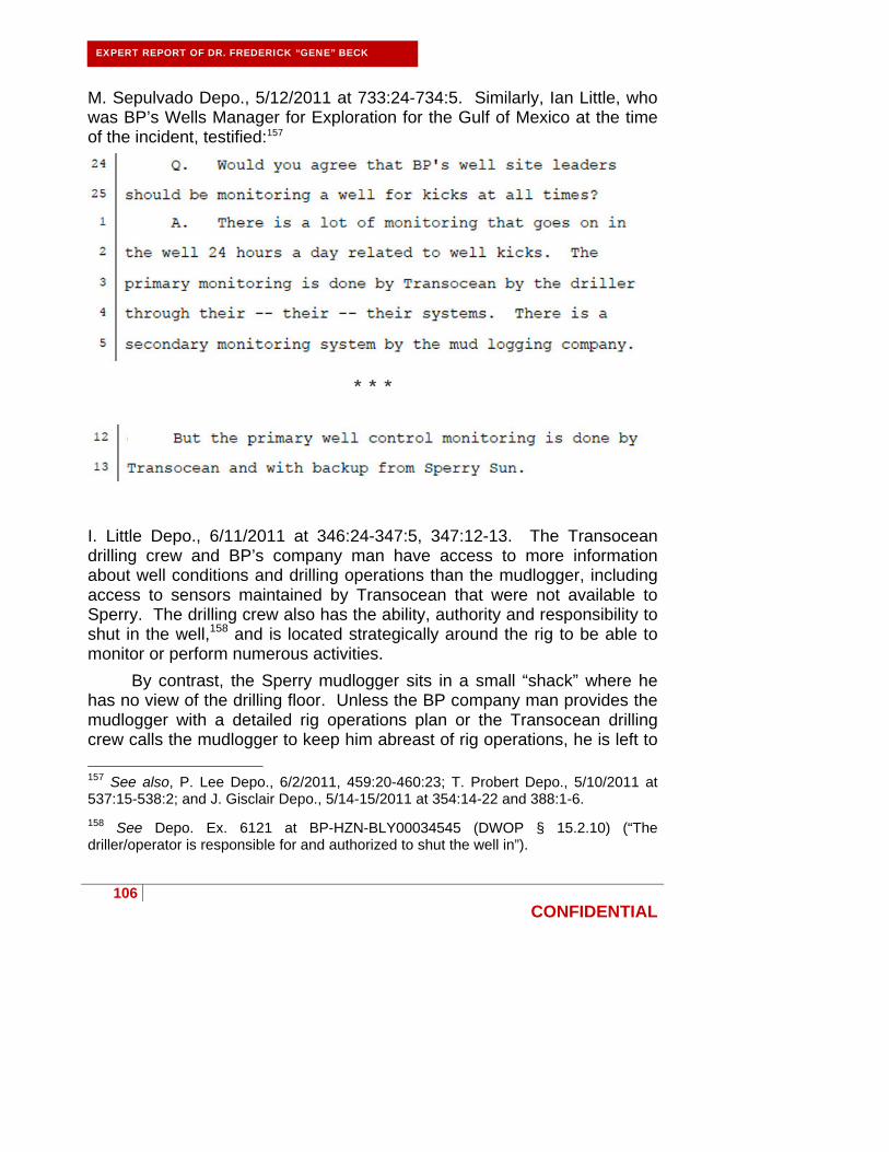
106
CONFIDENTIAL
EXPERT REPORT OF DR. FREDERICK “GENE” BECK
M. Sepulvado Depo., 5/12/2011 at 733:24-734:5. Similarly, Ian Little, who was BP’s Wells Manager for Exploration for the Gulf of Mexico at the time of the incident, testified:157
I. Little Depo., 6/11/2011 at 346:24-347:5, 347:12-13. The Transocean drilling crew and BP’s company man have access to more information about well conditions and drilling operations than the mudlogger, including access to sensors maintained by Transocean that were not available to Sperry. The drilling crew also has the ability, authority and responsibility to shut in the well,158 and is located strategically around the rig to be able to monitor or perform numerous activities.
By contrast, the Sperry mudlogger sits in a small “shack” where he has no view of the drilling floor. Unless the BP company man provides the mudlogger with a detailed rig operations plan or the Transocean drilling crew calls the mudlogger to keep him abreast of rig operations, he is left to
157 See also, P. Lee Depo., 6/2/2011, 459:20-460:23; T. Probert Depo., 5/10/2011 at 537:15-538:2; and J. Gisclair Depo., 5/14-15/2011 at 354:14-22 and 388:1-6.
158 See Depo. Ex. 6121 at BP-HZN-BLY00034545 (DWOP § 15.2.10) (“The driller/operator is responsible for and authorized to shut the well in”).

107
CONFIDENTIAL
EXPERT REPORT OF DR. FREDERICK “GENE” BECK
divine rig operations by analyzing data measured by a host of sensors throughout the rig, or by querying the Transocean crew members. I understand that during the final displacement, the Transocean drilling crew did not communicate rig activities to the Sperry mudlogger, leaving him in the dark.159 Common sense dictates that an individual in such a position would not be the primary line of defense against a catastrophic blowout and its potential financial and environmental consequences.
Additionally, the mudlogger has numerous duties unrelated to monitoring the well for kicks, including keeping track of all fluids used in the drilling process, calibrating the Sperry sensors, collecting and characterizing cutting samples from the well, monitoring for problems with rig equipment/sensors, preparing daily and end of well reports, and preparing the surface data logging unit for transfer.160 Indeed, the mudlogger does not have primary responsibility for kick detection.161 The Transocean driller, assistant driller, toolpusher, and offshore installation manager, and the BP company man are required by regulation to be certified every two years in kick detection,162 while the mudlogger is not. This reflects the prevailing understanding that a mudlogger is, at best, a “second set of eyes” for the drilling crew.163
The displacement procedure designed by M-I SWACO, executed by Transocean, and authorized by BP, put the Sperry mudlogger at a distinct disadvantage to members of the drilling crew who not only could monitor
159 Tr. of USCG/MMS Investigation (J. Keith testimony), 12/7/2010 at 193:11-15; see also J. Bellow Depo., 5/3/2011 at 610:4-9 (BP’s 30(b)(6) witness agreeing that “there is an expectation that the wellsite leadership will inform mudloggers of information that will affect their ability to do their job.”). 160 See, e.g., Depo. Ex. 609. 161 P. Lee Depo., 6/2/2011, 459:20-460:22 (“Q. The driller, the AD, the drilling crew are the -- have the primary responsibility for monitoring downhole conditions; would you agree with that? A. I think so, yes, sir.” (objection omitted)). Mr. Lee was a BP well site leader on the Deepwater Horizon.
162 30 CFR 250.401(d), 30 CFR 250 Subpart O; see also, e.g., TRN-MDL-00536818. 163 See, e.g., P. Lee Depo., 6/2/2011, 460:20-23; W. Wheeler Depo., 8/25/2011 at 95:22-96:1 (“Q. Okay. Did you rely on the Sperry-Sun mudloggers, or did you rely more on the -- your own data that the drill crew would get? A. I relied on mine.”); M. Burgess Depo., 4/20/2011 at 327:12-328:5 (“My primary ones I watched was the HiTech. That's the primary ones I watched. Sperry was a backup, in my book.”).
108
CONFIDENTIAL
primary kick-indicators unavailable to the mudlogger (such as flow-out while diverting), but also had full knowledge of the rig operations (such as staggering the pumps), as well as the ability to shut in the well (by activating the blowout preventer) in the event of a kick. These individuals, not the Sperry mudlogger, are responsible for missing and failing to respond to the kick that led to the Macondo blowout.164
The primary responsibility for well monitoring remained with Transocean throughout the displacement procedure according to Minerals Management Service regulation and Transocean’s own procedures. Minerals Management Service regulations require a member of the drilling crew on the rig floor to maintain “continuous surveillance.”165 Similarly, Transocean’s Well Control Handbook clearly states “[t]he Driller is responsible for monitoring the well at all times.”166 Despite this clear line of responsibility, Transocean’s expert, Mr. Barnhill, improperly attempts to shift this burden to the mudlogger by suggesting that the driller and two assistant drillers would have been distracted by other issues during the displacement.167 If a driller is distracted or busy, however, his responsibilities fall to one of the assistant drillers. If the Transocean driller and two assistant drillers were all too busy to keep an eye on the well, as Mr. Barnhill suggests, leaving the mudlogger as the sole and primary individual monitoring for a well control situation, someone from the crew should have at least called the mudlogger to let him know he had that responsibility.168 I have seen no evidence that anyone made such a call.
164 Further analysis regarding the displacement and the impact of additional simultaneous and non-standard operations can be found in Appendix C, describing mudlogging on the Deepwater Horizon generally and on April 20, 2010.
165 “You must take necessary precautions to keep wells under control at all times. You must: . . . (c) Ensure that the toolpusher, operator’s representative, or a member of the drilling crew maintains continuous surveillance on the rig floor from the beginning of drilling operations until the well is completed or abandoned, unless you have secured the well with blowout preventers (BOPs), bridge plugs, cement plugs, or packers.” 30 CFR 250.401(c) (emphasis added).
166 Depo. Ex. 590 at TRN-MDL-00286784 (Transocean Well Control Handbook, Section 1.3.6).
167 See, e.g., Barnhill Expert Report at 39-40.
168 Tr. of USCG/MMS Investigation (J. Keith testimony), 12/7/2010 at 193:11-15; see also J. Bellow Depo., 5/3/2011 at 610:4-9 (BP’s 30(b)(6) witness agreeing that “there is
EXPERT REPORT OF DR. FREDERICK “GENE” BECK
109
CONFIDENTIAL
Thus, the responsibility remained squarely with Transocean to monitor the well, aided by the mudlogger’s second set of eyes.
2. BP and Transocean conducted simultaneous and non-standard operations that obscured primary kick indicators during the final displacement.
Mudloggers perform a variety of tasks, but the primary task of a mudlogger is to set up, configure and maintain sensors, and to monitor data that pertains to a host of drilling-related parameters. These parameters are measured by sensors (such as a flow sensors and pit volume sensors) positioned at various locations around the rig. As part of maintaining this system, the mudlogger monitors the sensors’ output for anomalies.
Anomalies in pit volumes, or other parameters available to the mudlogger, can be caused by a number of different activities such as fluid transfers between pits, rig movement, crane activity, and, of course, an influx into the well. Significant anomalies that the mudlogger cannot reconcile are communicated to the driller, assistant driller, company man, toolpusher, and/or mud engineer so those individuals may determine whether the anomaly is an expected response, or a sign of a potential problem, such as a pipe washout, faulty sensor, or a kick.
On April 20, 2010, the Deepwater Horizon was preparing to abandon the Macondo well. To do so, BP’s plan called for underbalancing the well by replacing heavy drilling fluid with lighter seawater prior to setting a cement plug. All parties knew a kick could occur during this process, yet in their haste to move to a new drill site, BP, Transocean, and M-I SWACO elected to perform multiple simultaneous and non-standard actions without regard for safety or even their own standard operating procedures.169 These actions included:
an expectation that the wellsite leadership will inform mudloggers of information that will affect their ability to do their job.”). 169 Section 4.1.1 of Transocean’s Well Control Handbook states that individuals involved in rig activity should “[k]eep all mud treatment and pit transfers to the absolute minimum during critical sections of the well. The Mud Engineer and the Derrickman must keep the Driller and Mud Loggers informed of any transfers or treatments or mud.” Depo. Ex. 590 at TRN-MDL-00286819. Section 28.4 of BP’s DWOP states that “Major Accident Hazards as a result of Simultaneous Operations shall be identified so that controls and mitigations can be put in place before the activity takes place.” Depo. Ex. 6121 at BP-
EXPERT REPORT OF DR. FREDERICK “GENE” BECK

110
CONFIDENTIAL
EXPERT REPORT OF DR. FREDERICK “GENE” BECK
Diverting M-I SWACO’s lost circulation material spacer overboard in a manner such that the mudlogger could not monitor the amount of fluid flowing out of the well;
Transferring mud to the Damon Bankston and failing to notify the
mudlogger when this transfer ceased; Pumping seawater into the well from an unmonitored sea chest; Cleaning and emptying several mud pits; Repeatedly draining the trip tanks without notification; Draining the unmonitored sand traps; Conducting disruptive crane activities during critical well operations; Staggering pump speed; and Changing the pit that received well returns without notifying the
mudlogger so that he could change the designated active pit.170
Each of these actions frustrated the mudlogger’s ability to completely monitor the well for anomalies—a fact well known to both Transocean and BP since they also had access to Sperry’s mudlogging data in addition to Transocean’s more complete Hitec data. These actions had the ability to mask and confound primary indicators of a kick. Such indicators include:
Increase in pit volume;
Well flow with pump shut-down;
Increase in flow rate;
High gas units;
HZN-BLY00034593. See also Depo. Ex. 1575 (BP’s ETP GP 10-75—Simultaneous Operations). 170 A more detailed analysis of these activities and their impact on well monitoring can be found in Appendix C.

111
CONFIDENTIAL
EXPERT REPORT OF DR. FREDERICK “GENE” BECK
Decrease in pump or standpipe pressure;
Rate of penetration increase;
Sudden torque increase;
Change in mud chlorides; and
Reduction in mud ECD (equivalent circulating density).171
The latter four indicators would typically be present only during drilling operations and were not available as kick-indicators during the final displacement. During the final displacement, the remaining kick indicators were either bypassed, unreliable, or did not indicate a kick was occurring, as briefly described below.
a) BP and Transocean prevented Sperry from observing any pit volume gain.
A drilling rig like the Deepwater Horizon contains numerous “pits” or storage tanks which hold drilling fluids. Most of these pits include Transocean’s volume sensors which collect data that are transmitted to Transoceans’s drilling crew, BP’s company man, and the Sperry mudlogger. During traditional well operations fluid is pumped from, and returned to, the monitored pits. When the well is stable there will be no net fluid gain or loss.172 In this “closed loop” scenario, an influx into the well is easily detectible as a gain in the pits. However, this kick detection method was unavailable to the mudlogger during the final displacement because Transocean and BP chose to pump into the well from an unmonitored sea chest, rather than a monitored pit.
When fluid is pumped into the well from an unmonitored source, such as the sea chest, certain pits will show a steady gain that is not offset by a corresponding loss in another pit. In this “open loop” scenario, it is more difficult to ascertain whether a well is flowing. Once you factor in a myriad of fluid transfers, including transfers involving unmonitored pits (such as the “sand trap” or storage tanks on the Damon Bankston), it becomes nearly impossible to detect a kick using pit volumes—the mudlogger must perform
171 See, e.g., TRN-I NV-00800307 (IADC Deepwater Well Control Guidelines, 2002 at §2.1.1) for a list of “standard well kick warning signs.” 172 The process of mudlogging aboard the Deepwater Horizon is explained in greater detail in Appendix C.

112
CONFIDENTIAL
EXPERT REPORT OF DR. FREDERICK “GENE” BECK
numerous manual calculations throughout the displacement to account for all fluid transfers as best he can.173
Nevertheless, on April 20, 2010, the Sperry mudlogger was accurately monitoring the volume data available to him. This is evidenced by phone calls the mudlogger made regarding several anomalies. For example, one anomaly concerned an unexpected increase in pit level and rate of flow-out because Transocean and M-I SWACO chose to empty the unmonitored sand trap into the monitored pits during the displacement.174 Another anomaly was an unexpected increase in pit level because Transocean and M-I SWACO chose to empty the trip tanks across the flow line and into the monitored pits during the displacement.175 Neither of these anomalies in fluid volume detected by the mudlogger was actually a kick, but the mudlogger performed his duty by alerting the drilling crew of the anomalies. During the final displacement, the Sperry mudlogger placed calls pertaining to at least four anomalies, the two fluid volume anomalies, and two others related to pump speed and an irregular pressure spike.176
Once BP and Transocean diverted returns from the well overboard after the sheen test, the mudlogger’s pit monitoring system was bypassed completely and the Sperry mudlogger could no longer identify an influx using volumetric calculations.177
b) Sperry acted reasonably in checking for well flow.
Perhaps the clearest indication of a flowing well is to literally check for flow. This is the test done by the drill crew when a kick is suspected. To perform a flow check, all pumps and sources of fluid into the well are shut down and the well is left open to atmospheric pressure at the surface. If the well is not flowing, fluid should stop coming out of the well shortly after the pumps are turned off. If the well is flowing, fluid will continuously
173 J. Keith Depo., 3/28/2011 at 139:22-140:22, 144:14-24, and 145:2-10.
174 J. Keith Depo., 3/28/2011 at 74:9-75:5 and 317:1-318:1.
175 J. Keith Depo., 3/28/2011 at 170:15-171:2 and 231:22-233:18.
176 J. Keith Depo., 3/28/2011 at 74:9-75:5, 170:15-171, 231:22-233:18, 235:2-236:9, 237:8-14, 237:22-239:1, and 317:1-318:1.
177 Figures illustrating the relative positions of the Transocean and Sperry sensors on the Deepwater Horizon may be found in Appendix C and Depo. Ex. 607.

113
CONFIDENTIAL
EXPERT REPORT OF DR. FREDERICK “GENE” BECK
stream from the well. When the rig pumps were shut down at 9:08 PM for the sheen test, Mr. Keith checked the flow line and observed the monitored flow from the well cease after about a minute.178 Because the well did not appear to continue to flow when open to atmospheric pressure, one can reasonably make one of two conclusions: (1) the well was not flowing at this time, or (2) the Transocean drilling crew inappropriately diverted fluids overboard—and out of the mudlogger’s monitoring capability—before verifying that the well was indeed not flowing. Either way, a reasonable mudlogger, witnessing the cessation of flow at 9:09 PM on April 20, 2010 would have concluded the well was stable and not flowing based on his belief that the sensor upon which he was relying was not prematurely bypassed by the Transocean drilling crew.
c) BP and Transocean failed to identify an increase in flow following the sheen test.
Another kick indicator is an unexplained increase in flow from the well. When Sperry’s flow-out sensor is accurately calibrated, it can still have at least 10% error.179 Compounding this error is the fact that flow-out sensor readings are highly susceptible to rig movement. A slight shift in rig position due to ballasting or crane movement can have a significant impact on the flow rate “seen” by the sensor. For this reason, a mudlogger primarily uses a flow-out sensor to monitor for trends, rather than accurate volumetric measurements. This well known limitation, however, has not stopped other parties to this action from improperly attempting to detect a kick by computing pit gain using the Sperry flow-out data.180
The surviving Sperry flow-out data from the Macondo final displacement is “noisy.” This is caused by crane operations and fluid transfers. For example, the drilling crew dumped a trip tank down the flow line twice during the final displacement, causing an increase in flow-out that
178 Depo. Ex. 604; J. Keith Depo., 3/28/2011 at 151:17-152:17 and 236:16-22. 179 Tr. of USCG/MMS Investigation (J. Gisclair testimony), 10/8/2010 at 100:7-15. 180 See, e.g., Appendix S to BP’s Bly Report, which applied a calibration to the surviving flow-out data, and then used this data to calculate a supposed influx. The accuracy of this after-the-fact calibration is suspect for a variety of reasons. For example, this calibration cannot account for intermittent error sources, like crane activity or rig ballasting, that introduce inaccuracies into the Sperry flow-out sensor’s data, as described in Appendix C.

114
CONFIDENTIAL
EXPERT REPORT OF DR. FREDERICK “GENE” BECK
some parties’ experts have misinterpreted as an increase in well flow.181 As indicated above, these simultaneous operations compromised the ability of the mudlogger to monitor the well during the critical final displacement.
As we now know, eventually there was an influx into the well. The vast majority, if not all, of this kick occurred while Transocean and BP were diverting the well returns overboard. The Sperry flow-out meter was bypassed when diverting returns overboard, and the Sperry mudlogger did not have an opportunity to detect the increased flow. This fact was known by both the Transocean drilling crew and the BP company man, since they had access to data from the Sperry sensor. Notably, Transocean had its own flow-out sensor that was not bypassed. This data was not provided to the Sperry mudlogger, but was accessible by the Transocean drilling crew and the BP company man.182 It is unknown why the Transocean drilling crew or the BP company man did not identify what was surely a tremendous increase in well flow after the sheen test.
d) BP and Transocean prevented Sperry from monitoring gas concentration.
An additional kick indicator is the presence of gas in fluid coming from the well. On the Deepwater Horizon, gas concentration in the drilling fluid was measured by a Sperry sensor placed in the rig’s “possum belly,” a piece of equipment located downstream from the flow-out line. During the final displacement, the fluid pumped from the well exhibited no significant increase in gas concentration. However, like the Sperry flow-out sensor, the Sperry gas concentration sensor was bypassed when returns were diverted overboard. Thus, after approximately 9:09 PM, the Sperry mudlogger was unable to monitor gas concentration as a potential kick indicator.
181 See, e.g., Richard Heenan Report for the United States at 22.
182 During his deposition, Micah Burgess, a Transocean driller, confirmed that he relied upon the Hitec system, and would not be hampered in his ability to monitor the well if a Sperry sensor was unavailable. M. Burgess Depo., 4/20/2011 at 327:12-328:5 (“Q. So if you learned that a Sperry-Sun gauge was for some reason unavailable for use, that wouldn’t stop you from being able to do your job? A. No.”).
115
CONFIDENTIAL
EXPERT REPORT OF DR. FREDERICK “GENE” BECK
e) Detection of pressure anomalies was complicated by the lack of a predicted pressure/volume schedule
Both the Sperry mudlogger and the Transocean drilling crew would have benefited from a pressure/volume schedule “to show the expected pressures in the well” at different stages of the displacement, as recommended in an “Operations Advisory” published by Transocean following a similar prior kick incident on another Transocean rig.183 This pressure/volume schedule would be a simple schedule that provides expected pressures and volumes during the displacement. The Macondo final displacement involved a complex drill string geometry, multiple pump speeds, changing fluid densities, and an unnecessarily large volume of a non-standard spacer on a well that was known for being difficult. Even the most senior hand on the rig would not have intuitively known what pressure responses to expect.
A reasonably prudent operator would have calculated a pressure/volume schedule beforehand, and distributed the schedule to the Transocean drilling crew, the M-I SWACO mud engineer, the Sperry mudlogger, and anyone else involved in the displacement. Such a schedule would have aided in the detection of anomalies, even anomalies unrelated to a kick, that may have suggested whether there were any problems with the well.
Because other more traditional kick-indicators were obscured from the Sperry mudlogger by Transocean and BP’s actions, much has been made of the 200 psi rise in standpipe pressure during the sheen test. While this pressure may be significant in hindsight, a reasonable mudlogger could have attributed this pressure to the weighted spacer which remained in the riser.184 Of course, the 200 psi increase in standpipe pressure would have been more meaningful for the BP and Transocean personnel who would have seen the standpipe pressure increase combined with any increase in flow.
After the sheen test, pressure generally tracked pump speed, as one would anticipate for the next several minutes. This may explain why Mr.
183 Depo. Ex. 1520.
184 See, e.g., J. Keith Depo., 3/28/2011 at 103:16-25.

116
CONFIDENTIAL
EXPERT REPORT OF DR. FREDERICK “GENE” BECK
Keith did not see anything anomalous about the standpipe pressure upon his return from a short break. While there is no indication that Mr. Keith notified the driller of the anomalous pressure response at 9:30 PM, it is evident from the data and the cessation of pumping that the Transocean drilling crew had already identified this anomaly and was investigating, as described in the Barnhill report.185
f) A reasonable mudlogger would not have focused on hookload as a kick indicator.
Some have suggested that Joseph Keith should have focused on hookload to detect a kick on April 20, 2010.186 Hookload is not a traditional kick indicator. API RP 59 Sec. 6 identifies several “Well Control Warning Signals,” including many which are not typical—fluctuation in hookload is not even mentioned. Hookload fluctuation is also not mentioned in the “standard well kick warning signs” provided by the IADC.187 A reasonable mudlogger exercising ordinary care would not have recognized the slight fluctuations in hookload during the final displacement as an indicator that the well was flowing.
3. While not available in real time, post-incident analysis suggests there was little to no well flow before diverting overboard.
I have performed an analysis of the surviving Sperry mudlogging data and conclude that the earliest that flow from the well can arguably be detected is around 9:06 PM.188 Between 9:06 PM and when Transocean and BP diverted returns overboard at approximately 9:09 PM, at most, about 10 bbls of excess fluid entered the pits. I want to stress, however, that this analysis took a great deal of effort and used techniques that would not be used by a reasonable mudlogger to perform a similar analysis in real time.
Because the multiple simultaneous and non-standard operations during the final displacement renders the flow-out data noisy and
185 See, e.g., Barnhill Expert Report at 40-41.
186 See Pritchard Expert Report at 22, 368; Marshall Islands Report at 51. 187 TRN-I NV-00800307 (IADC Deepwater Well Control Guidelines, 2002 at §2.1.1). 188 A real time video of the mudlogging data from April 20, 2010 is found in Appendix D.
117
CONFIDENTIAL
EXPERT REPORT OF DR. FREDERICK “GENE” BECK
unreliable, my conclusions are based upon an analysis of the pit volume data from 8:02 PM through 9:10 PM. Also, like flow out, pit volume totals can be impacted by rig movement caused by, for example, crane activity.189
While I conclude a 10 bbls influx is possible, it is just as likely that there was no influx preceding the sheen test at 9:10 PM, and any unexpected gain or flow out was due to crane or other activity that caused movement of the rig.
Because pit volumes are susceptible to rig movement, the typical kick detection resolution on the Deepwater Horizon was at times as high as 30 bbls, depending on rig activity.190 During a displacement fraught with simultaneous and non-standard activities, I suspect the kick detection resolution was closer to the 30 bbls extreme, meaning that until a kick reached about 30 bbls, it is doubtful a reasonable mudlogger could have detected the kick.
a) Sperry’s mudlogger acted reasonably under the circumstances.
I understand that Joseph Keith, the mudlogger on tour the night of April 20, 2010, was highly regarded for his well monitoring abilities.191
189 TRN-I NV-00800309 (IADC Deepwater Well Control Guidelines, 2002 at §2.1.6) (One known limitation of pit volume monitoring is that “[p]itch, roll, and heave motions (due to weather, crane, etc.) can significantly impact pit level and mud return detection methods.”). See also, R. Sepulvado Depo., 3/10/2011 at 32:25-34:10 and 533:22-534:8; P. Lee Depo., 6/2/2011, 455:14-457:18; M. Sepulvado Depo., 5/11/2011 at 374:3-11; J. Keith Depo., 3/28/2011 at 67:3-13, 67:19-68:2, 163:3-22, and 170:9-171:11; C. Breland Depo., 5/18/11 at 68:9-70:19; J. Bellow Depo., 5/3/2011 at 487:2-488:2. 190 See R. Sepulvado Depo., 3/10/2011 at 32:25-34:10 and 533:22-534:8 (“The flow shows will change, the crane operations make them change, swing the crane with a load over the side, you may get a 30-barrel increase in volume pretty quick. . .And that’s the same thing you see when you get a kick out of the well, in the well.”); P. Lee Depo., 6/2/2011, 455:14-457:18; M. Sepulvado Depo., 5/11/2011 at 374:3-11; J. Keith Depo., 3/28/2011 at 67:3-13, 67:19-68:2, 163:3-22, and 170:9-171:11; C. Breland Depo., 5/18/11 at 68:9-70:19; J. Bellow Depo., 5/3/2011 at 487:2-488:2. 191 See, e.g., M. Sepulvado Depo., 5/12/2011 at 649:15-650:14 (“[H]e [Keith] was a good mudlogger.” and “He [Keith] called me every time there was something abnormal that turned up.”); P. Lee Depo., 6/2/2011, 453:24-455:13 (“I thought he was very good at what he did. I thought he was a good mudlogger.”); J. Bellow Depo., 5/3/2011 at 464:1-13; K. Kronenberger Depo., 8/2/2011 at 200:6-10, 224:8-19.
118
CONFIDENTIAL
EXPERT REPORT OF DR. FREDERICK “GENE” BECK
Indeed, when the Deepwater Horizon was first brought into service in the Gulf of Mexico, BP specifically requested that Sperry assign Keith to the Deepwater Horizon.192 At the time of the Macondo incident, Keith had been working in the Gulf of Mexico for 18 years, 7 of which were on the Deepwater Horizon.193 Keith has attended hundreds of hours of training and safety classes over the years, and while it is not required for mudloggers, Keith has even attended Well Control School.194
I believe that given the circumstances of the final displacement, the Sperry mudlogger accurately monitored the well data available to him. In so doing, the Sperry mudlogger noticed and communicated several anomalies, including abnormal pit gains, a pressure spike, and unexplained pumping actions.195 Each time, the mudlogger received confirmation from Transocean or M-I SWACO personnel that the well was normal and the anomaly was expected.
In conclusion, on April 20, 2010, the Sperry mudlogger did not miss any obvious signs of a kick that would have been detected by a reasonable mudlogger. Despite adverse conditions created by the simultaneous and non-standard operations specified by BP, Transocean, and M-I SWACO, Joseph Keith adequately monitored the data available to him.
VIII. Summary Of Key Findings.
In conclusion, upon review of available information, I have made the following critical findings:
BP systematically chose to ignore industry standard “Good Drilling Practices,” many of which had been recognized by BP in its own written practices, thus materially increasing risk on the well.
The wellbore as drilled by BP was damaged and dangerously
unstable.
192 J. Keith Depo., 3/28/2011 at 45:8-16. 193 J. Keith Depo., 3/28/2011 at 45:4-7, 68:13-15, 127:18-128:11. 194 See, e.g., HAL_0532808; J. Keith Depo., 3/28/2011 at 23:19-24:2. 195 Further details may be found in Appendix C, which provides a timeline of relevant displacement activities.

119
CONFIDENTIAL
EXPERT REPORT OF DR. FREDERICK “GENE” BECK
BP chose not to repair the damaged wellbore in a prudent manner. BP chose to install the production casing in a long string
configuration. A liner configuration would have offered a far safer alternative.
BP designed and operated a shoe track that was inadequate for the
well conditions. BP damaged and failed to convert the auto-fill float collar and
possibly damaged the shoe track during the conversion process. BP chose to ignore the probability that the float equipment was
damaged and did not take immediate corrective action, acting imprudently during subsequent well operations.
BP chose to place centralizers around the casing in a manner
inconsistent with good cementing practices and against the recommendation of Halliburton.
BP chose not to circulate bottoms up prior to cementing the well,
adding to the unstable conditions in the wellbore. BP declined to run a cement bond log to evaluate the results of the
cementing operations. BP failed to ensure that the negative pressure test was designed,
executed, and interpreted properly. BP failed to recognize the obvious results of the negative pressure
test. This was particularly remarkable given the fragile nature of the well and the trouble converting the float collar. BP should have been extra careful in performing integrity testing on the well, but instead BP was reckless in failing to maintain diligence and extreme caution throughout the testing procedure.
BP devised an out-of-sequence temporary abandonment procedure
that unnecessarily underbalanced the well.
120
CONFIDENTIAL
EXPERT REPORT OF DR. FREDERICK “GENE” BECK
BP and Transocean failed to conduct the displacement to seawater in a manner that allowed adequate kick detection.
BP failed to provide adequate rig site supervision.
All of these findings contributed to the blowout in varying degrees;
however, BP’s damaging of and failure to convert the float collar and BP’s disregard for the negative pressure test results stand as the direct causes of the blowout. Prior to the negative pressure test, a blowout was not imminent on the Macondo well. Difficult well conditions, failed float collars, cementing issues and lost circulation can all be overcome or repaired by prudent operations. The negative pressure test was the critical and final checkpoint conducted to assure well integrity, and once BP ignored this checkpoint, the risk of blowout increased dramatically on a minute-by-minute basis, with no room for error.
The blowout was caused when BP removed the drilling fluid from the well, exposing the well to the full effects of a high pressure, highly productive oil reservoir and allowing hydrocarbons to flow into the well in an uncontrolled manner. This reservoir produced at extremely high volumes and hydrocarbons reached the surface rapidly after the well was underbalanced. Blowout prevention in the face of this type of reservoir is predicated on careful risk management, well planning, and operations management to assure that conditions that can even remotely lead to a blowout are avoided at all cost. BP failed miserably in all three arenas.
The decision-making at the rig site on the day of the Macondo blowout was reckless. BP’s acceptance of the negative pressure test as proof of well integrity is incomprehensible and inexcusable in and of its own. Accepting the “bladder effect” as a rationale for the pressures observed by BP drilling supervisors Kaluza and Vidrine is inexcusable. Poor decisions by these BP supervisors, including accepting bad advice from Transocean personnel, led directly to the blowout. As such BP, and to lesser extent Transocean, are responsible for the blowout.

121
CONFIDENTIAL
EXPERT REPORT OF DR. FREDERICK “GENE” BECK
I reserve the right to modify this report and to supplement my opinions if additional data becomes available and in response to reports served by other parties.
Dated: November 10, 2011
___________________________________
Frederick Eugene Beck