Embed Size (px)
Citation preview
Journal of
Materials Processing Technology
E L S E V I E R Journal of Materials Processing Technology 54 (1995) 271-285
Expert system for multi-stage cold-forging process design with a re-designing algorithm
Hong-Seok Kim, Yong-Taek Im* Department of Mechanical Engineering, Korea Advanced Institute of Science and Technology, 373-1, Kusung-dong,
Yusong-gu, Taejon 305-701, South Korea
Received 19 May 1994
Industrial summary
Cold forging has recently become one of the competitive technologies in manufacturing. In order to impove the productivity of cold forging at low production cost, an integrated systems approach is necessary in handling the material preparation and the optimum process design considering the forming machines, tooling, and operation, including quality control. As the first step toward this approach, an expert system for multi-stage cold-forging process design for axi-symmetric geometries with or without a hole in one end has been developed using Prolog language on IBM 486 PC. The system consists of a user interface, a system shell, a material data-base, and a design rule-base. According to the given input data, the system generates the forgeable geometry and the basic process design, depending on the initial billet size and material or the order of upsetting and forward extrusion. In addition, it can provide a flexible process re-design based on either the reduction in the number of forming sequences by combining the possible two processes in sequence, or the reduction of deviation of the distribution and the level of the required forming loads at the last forging step by controlling the forming ratios. The required forming loads and global strain distributions at each step are calculated and displayed on a PC monitor. The designed process sequences can be obtained by AutoCAD or a text file including the dimensions of the drawing. The system developed will be useful in reducing trial-and-error by design engineers in determining the diameter and height of the initial cyclindrical billet from the final product geometry and the intermediate necessary sequences.
1. Introduction
Multi-stage cold forging of axi-symmetric parts con- sists of several processes of shearing, sizing, upsetting or heading, forward and backward extrusion, punching, etc. The process design depends on the characteristics of such processes. Cold forging has its major advantages for making axi-symmetric parts of small or medium sizes on multi-stage automatic forging machines or on conven- tional presses in several steps. It can produce parts with good surface finish, dimensional accuracy and improved mechanical properties, and also eliminate extra post-pro- cessing such as trimming and machining. However, the economy of producing defect-free cold-forged parts relies on the mechanism of the die design of the sequential processes, which has been heavily dependent on the level of skill of die design engineers based on their working experience. Therefore, the automatic design of process sequences for multi-stage cold forging operations is of importance.
* Corresponding author.
0924-0136/95/$09.50 © 1995 Elsevier Science S.A. All rights reserved SSDI 0 9 2 4 - 0 1 3 6 ( 9 4 ) 0 1 7 7 4 - U
According to recent development of computer techno- logy, the application of computers in manufacturing has been growing rapidly in the area of CAD/CAM(Com- puter Aided Design/Computer Aided Manufacturing), CAE(Computer Aided Engineering), CAPP(Computer Aided Process Planning), and numerical simulations of manufacturing processes using numerical techniques. In the area of process planning of forming processes, a num- ber of developments have been reported after pioneering work by Niebel [1] and Barker [2] in the late 1960s. In the 1970s, Akgerman and Altan [3] developed a CAD system for hot forging, Biswas and Knight [4] extending their work. The system developed is, in general, com- posed of several modules to assist the users in generating forging design rules that are incorporated into the pro- grams and formulated on the basis of grouping relations and process limitations relevant to each operations [5-12].
In addition, due to the development of knowledge treatment technique, knowledge based manufacturing systems have become popular, based on qualitative and ambiguous human experiences. In these systems, expert system [13], neural network or fuzzy theory [14, 15], and
272 H,-S. Kim, E-T. Im / Journal of Materials Processing Technology 54 (1995) 27l 285
artifical intelligence [16] are used with the help of the operator's skill. It is widely known that the expert system has emerged as one of the most active and fruitful areas for research in the application of human knowledge for problems which do not lend themselves to solution by conventional methods because of a lack of quantitative data regarding the input output relations. Expert sys- tems can therefore provide a user-friendly, flexible, intelli- gent solution to the kind of problem involving complex logic which occurs in engineering, automatic generation of sequence design for multi-stage cold forging being a good example.
In the present investigation, an expert system that can determine the number and the geometries of the inter- mediate steps in the multi-stage cold forging of axi-sym- metric geometries with or without a hole in one end has been developed, the program being developed using Prolog language on a IBM 486 PC. The system consists of a user interface, a system shell, a material data-base, and a rule-base. The system shell has graphic, input and output modules, an inference engine and a working mem- ory. In order to make the system more flexible, the material database and rule-base are separated from the system shell, being obtained from materials handbooks, references, and interviews with die-design engineers [-17, 18]. According to the given input data, the expert system developed can produce the basic process design depending on the initial billet size and material, or the order of upsetting and forward extrusion, and the flexible process re-design based on either reduction of the num- ber of sequences by combining the possible two processes in sequence, or reduction of deviation of the distribution and the level of the required forging loads at the last forging step by controlling the forming ratios. It also has the function of displaying the required forging load and level of strain at each step and of producing the output of the designed process sequences using AutoCAD or a text- file. Several examples demonstrate the capability of the expert system developed are discussed later in the paper.
2. Overall structure of the system developed
billet size
/ Final Product Shape ~ - ~
Input Use another ¢ material
Change ._~ Determination of Initial Billet Size initial /
flow
Bad I
Good
Determination of Geometry Group
Determination of Cold Forging Process for Each Element
Generation of Process Sequence
Calculation ~-~ Forming Pressure Modules I I Forming Load
Effective Strain
,Unsatisfied
Redesign Modules
"-[~ I Output ~ _ { Text AutoCADFile
~ Reduction of the Number of Processes Forming Load
Fig. 1. Flow chart of the expert system developed.
rule-base directory. The current program can handle axi-symmetric cylindrical geometries with decreasing diameter in one or both ends or a cylindrical shape with decreasing diameter having a hole on the top. Since the program structure has individual rule-bases for solid and hollow cylinders, each rule-base is applied according to the given geometry. Based on the designed forging se- quences, the dimension, forming strain, and load are calculated accordingly. The designed process sequences and the calculated processing data can be displayed on the PC monitor or stored in the form of a output file.
The overall structure of the expert system developed is depicted in Fig. 1, the system being written in Prolog language on an IBM 486 PC. It is composed of a system shell including input and output modules, and an infer- ence engine. The material data-base and rule-base are separated from the system shell such that a new material data-base or rule-base can be augmented easily with the developed system without modifying the system shell. The process design was obtained from the system by the following procedures.
Once the final product geometry and the material type are provided as input, the expert system determines the forging sequences using the design rules stored in the
2.1. Input." product geometry and material
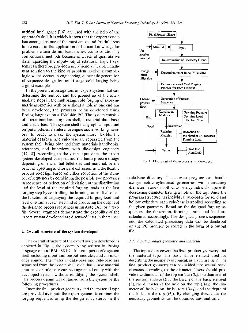
The input data covers the final product geometry and the material type. The basic shape element used for describing the geometry is conical, as given in Fig. 2. The final product geometry can be divided into several basic elements accroding to the diameter. Users should pro- vide the diameter of the top surface (Do), the diameter of the bottom surface (D1), the height of the basic element (L), the diameter of the hole on the top (Hdo), the dia- meter of the hole on the bottom (Hdl), and the depth of the hole on the top (Ha). By changing these data the necessary geometries can be obtained automatically.
H.-S. Kim, Y.-T. Im / Journal of Materials Processing Technology 54 (1995) 271-285 273
2, DO : diameter of top surface DI : diameter of bottom surface L : height of the element HdO : diameter of hole on top Hdl : diameter of hole on bottom H1 : depth of hole on top
Final Product Geometry
~ D0 element l D1
element 2 L
f " ~ HdO hole 1 Hdl
hole 2 HI
Fig. 2, Graphical representation of input data and schematic geometry of basic element.
decreasing diameter in one or both ends (solid) and the other a solid cylinder with decreasing diameter in one end having a hole on the top surface (hollow). Each group has an individual rule-base. Once the group is determined, the relevant rule-base is available in the working memory.
The advantages of utilizing individual rule-base for each geometry group are as follows: (i) the expendability and flexibility of rule-base are better; (ii) the size of necessary rule-base to be used becomes small; (iii) since the appropriate rule-base is available in the working memory based on the final product geometry, a possible mistake of using similar rules will be greatly reduced; and (iv) the computation time is reduced by decreasing the number of rules to be traced in determining the right rule.
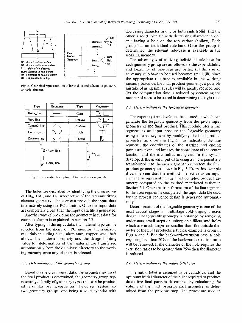
Type Geometry
Hofiz line
Vert_line I
Tapered_line / \
Convex_arc ~ J
Concave_arc k,._ /I"
CL
~" Vert_line
1 ~ Horiz_line
Type Geometry
Cone
Convex E 7
Concave ~ [ 7
Bolt [ - ]"]
Th ad CL
! ~ ,t-.,. Cone
J Fig. 3. Schematic description of line and area segments.
The holes are described by identifying the dimensions of Hdo, Hdl, and H1, irrespective of the circumscribing element geometry. The user can provide the input data interactively using the PC monitor. Once the input data are completely given, then the input data file is generated.
Another way of providing the geometry input data for complex shapes is explained in section 2.3.
After typing in the input data, the material type can be selected from the menu on PC monitor, the available materials including steel, aluminum, copper, and their alloys. The material property and the design limiting value for deformation of the material are transferred automatically from the data-base directory to the work- ing memory once any of them is selected.
2.3. Determination of the forgeable geometry
The expert system developed has a module which can generate the forgeable geometry from the given input geometry of the final product. This module uses a line segment as an input produce the forgeable geometry using an area segment by modifying the final product geometry, as shown in Fig. 3. For indicating the line segment, the coordinates of the starting and ending points are given and for arcs the coordinate of the center location and the arc radius are given. In the system developed, the given input data using a line segment are transformed into the area segment to represent the final product geometry, as shown in Fig. 3. From this example it can be seen that the method is effective as an input element in representing the final complex product ge- ometry compared to the method mentioned earlier in Section 2.1. Once the transformation of the line segment to the area segment is completed, the input data file used for the process sequence design is generated automati- cally.
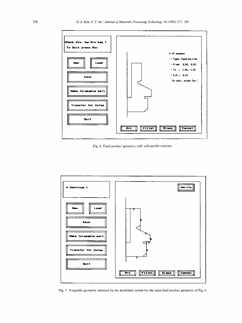
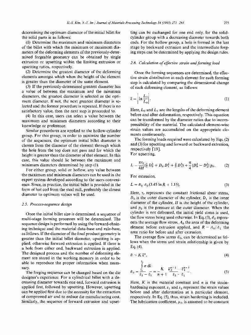
Determination of the forgeable geometry is one of the most crucial stages in multistage cold-forging process design. The forgeable geometry is obtained by removing under-cuts, small steps or unforgeable fillets, and holes which are much larger or smaller than the outside dia- meter of the final products: a typical example is given in Figs. 4 and 5. For the backward-extrusion case, a hole requiring less than 20% of the backward extrusion ratio will be removed. If the diameter of the hole requires the extrusion ratios to be greater than 75% then the diameter is reduced.
2.2. Determination o f the geometry group 2.4. Determination of the initial billet size
Based on the given input data, the geometry group of the final product is determined, the geometry group rep- resenting a family of geometry types that can be produc- ed by similar forging sequences. The current system has two geometry groups, one being a solid cylinder with
The initial billet is assumed to be cylindrical and the optimum initial diameter of the billet required to produce defect-free final parts is determined by calculating the volume of the final forgeable part geometry as deter- mined from the previous step. The procedure used in
274 H.-S. Kim, Y.-T. lm / 3ournal of Materials Processing Technology 54 (1995) 271 285
-11- ~ a ~ m
I1al(e f o r g m a b l e P a r t
T r a n s f @ r f o r C o f e s
Q u i t
m IO le~ent
- T~pcq Tapered_line
- Irromt 3.50, 3.20
- To 8 l.l~p 4.20
- L / R z 2 . 2 4
TO quit, prl~s Esc !
Fig. 4. Final product geometry with unforgeable sections.
w C o n t I u t
I - I I - 0 D ,M I I I~llke f o r g l l a b l e p a r t I
T r a n S f e r f o r C o r e s 0
D [l~lt 1
Fig. 5. Forgeable geometry obtained by the developed system for the same final product geometry of Fig. 4.
H.-S. Kim, Y.-T. Im / Journal of Materials Processing Technology 54 (1995) 271 285 275
determining the optimum diameter of the initial billet for the solid parts is as follows:
(1) Determine the maximum and minimum diameters of the billet with which the minimum or maximum dia- meters of the deforming elements of the previously-deter- mined forgeable geometry can be obtained by single extrusion or upsetting within the limiting extrusion or upsetting ratios, respectively.
(2) Determine the greatest diameter of the deforming elements amongst which when the height of the element is greater than the diameter of the same element.
(3) If the previously-determined greatest diameter has a value of between the maximum and the minimum diameters, the greatest diameter is selected as the opti- mum diameter. If not, the next greatest diameter is se- lected and the former procedure is repeated. If there is no satisfactory value, then the next step is proceeded to.
(4) In this case, users can select a value between the maximum and minimum diameters according to their knowledge or preference.
Similar procedures are applied to the hollow-cylinder group. For this group, in order to minimize the number of the sequences, the optimum initial billet diameter is chosen from the diameter of the element through which the hole from the top does not pass and for which the height is greater than the diameter of that element. In this case, this value should lie between the maximum and minimum diameters determined by step (1).
For either group, solid or hollow, any value between the maximum and minimum diameters can be used in the expert system developed according to the users conveni- ence. Since, in practice, the initial billet is provided in the form of hot coil from the steel mill, preferably the closest diameter to optimum values will be used.
2.5. Process-sequence design
Once the initial billet size is determined, a sequence of multi-stage forming processes will be determined. The sequence design is performed by using the forward-chain- ing technique and the material data-base and rule-base, as follows. If the diameter of the final product geometry is greater than the initial billet diameter, upsetting is ap- plied, otherwise forward extrusion is applied. If there is a hole from either end, backward extrusion is applied. The designed process and the number of deforming ele- ment are stored in the working memory in order to be able to reproduce the proper information when neces- sary.
The forging sequence can be changed based on the die designer's experience. For a cylindrical billet with a de- creasing diameter towards one end, forward extrusion is applied first, followed by upsetting. However, upsetting can be applied first due to the necessity for the extraction of compressed air and to reduce die manufacturing cost. Similarly, the sequence of forward extrusion and upset-
ting can be exchanged for one end only, for the solid- cylinder group with a decreasing diameter towards both ends. For the hollow group, a hole is formed in the last stage by backward extrusion and the intermediate forg- ing steps can be determined by applying the design rules.
2.6. Calculation of effective strain and forming load
Once the forming sequences are determined, the effec- tive strain distribution at each element for each forming step is calculated by comparing the dimensional change of each deforming element, as follows:
= In ~ . (1)
Here, Lo and LI are the lengths of the deforming element before and after deformation, respectively. This equation can be transformed by the diameter ratios due to incom- pressibility of the material. The calculated element-wise strain values are accumulated on the appropriate ele- ments continuously.
The forming loads required were calculated by Eqs. (2) and (3) for upsetting and forward or backward extrusion, respectively [19]. For upsetting,
__-- '/~Tf t2[1 D 3 L ~-~ o + D o O x z+-~D 3 ) + 4 ( D ~ - D z l ) (2) Po.
For extrusion,
L = 60 Ao (3.45 lnR + 1.15). (3)
Here, zf represents the constant frictional shear stress, Do is the outer diameter of the cylinder, D~ is the inner diameter of the cylinder, H is the height of the cylinder, and Po is the pressure at the outer diameter. When the cylinder is not deformed, the initial yield stress is used, the flow stress being used otherwise. In Eq. (3), fo repres- ents the average flow stress, A0 the area of the deforming element before extrusion applied, and R = Ao/A1 the area ratio for before and after extrusion.
The average flow stress fro, can be determined as fol- lows when the stress and strain relationship is given by Eq. (4).
6 = K ~", (4)
e2 y f d ~
60 ~', K ~ + i _ ~]+1 - _ ~ - - - ( 5 )
Here, K is the material constant and n is the strain- hardening exponent, el and ez represent the strain values before and after deformation at a particular element, respectively. In Eq. (5), thus, strain hardening is included. The lubrication coefficient, p f, is assumed to be constant
276 H.-S. Kim, E-~ Im / Journal of Materials Processing Technology 54 (1995) 271 285
as 0.04 during deformation, although it can vary in the program.
2.7. Output
The designed process sequence and dimensions, includ- ing the calculated forming strains and loads, can be displayed on the PC monitor and stored as a text file or a commercial AutoCAD file to produce a hard copy of the drawing for forging.
3. Redesigning algorithm
In order to determine the optimum process sequence design, several parameters such as the total number of stages, strain distribution and load requirement, tooling cost and life, etc., should be considered. Since these para- meters are coupled together, a decision is very complex to make and formulate. Thus, in the present investigation a re-designing algorithm was proposed and implemented in the system in order to reduce the number of forming stages and element-wise deviation in the total load re- quirement at the last stage of deformation by combining possible stages in sequence and/or adjusting the forming ratios, the initial billet size, and the forming order.
The re-designing algorithm consists of basic and ap- plied re-design. The basic re-design algorithm covers the case when the initial billet size or material and the order of forming stages are changed, whilst the applied re- design works for the case of reducing the number of stages and making the element-wise load requirements relatively even. With this re-designing scheme the expert system developed can produce more economical multi- stage process design for cold forging.
3.1. Basic re-design
The multi-stage cold forging of axi-symmetric parts investigated in this study consists of a combination of shearing, upsetting or heading, forward and backward extrusion. The basic design rules for upsetting and for- ward and backward extrusion used in the present invest- igation are as follows.
(1) The forward extrusion ratio, R1, backward extru- sion ratio, R2, and upsetting ratio, R3 are defined individ- ually by R1 = ln(Ao/A1), R 2 = d2/D 2, and R 3 = Lu/Du. Here, Ao represents the cross-sectional area of the material before extrusion, A1 the cross-sectional area of the material after extrusion, D the outer diameter of the backward-extruded material, d the inner diameter of the hole of the extruded material, Lu the length of the un- supported section, and Du the diameter of this section.
(2) If R~ is less than the limiting value for open for- ward extrusion of the material stored in the data-base in the system, the element will be formed by open extrusion.
(3) If R1 is greater than the limiting value for open forward extrusion and less than the limiting value for trapped extrusion, the element will be formed by trapped extrusion.
(4) If R1 is greater than the limiting value for trapped extrusion and less than the sum of the limiting values for open and trapped forward extrusion, the element will be formed by single open forward extrusion and trapped forward extrusion.
(5) If R1 is greater than the sum of the limiting values for open and trapped forward extrusion and less than twice of the sum of the limiting values for open and trapped forward extrusion, the element is formed by single open forward extrusion and trapped forward ex- trusion by two blows.
(6) If R 2 is greater than 0.2 and less than 0.75 and the depth of the hole is less than three times the hole dia- meter, the hole in the element is deformed by single backward extrusion.
(7) If the hole can not be formed by backward extru- sion only, a smaller-sized hole is formed as an intermedi- ate step and then the final dimension is formed by cup extrusion. In this case, the hole diameter at the intermedi- ate step is limited to 4/3 times the final hole diameter.
(8) If R3 is less than 2.3, the element is deformed by single upsetting.
(9) If R3 is greater than 2.3 and less than 4.5, the element is deformed by upsetting by two blows.
(10) When the element is deformed by upsetting by two blows, then the conical perform shape is obtained by the first upsetting.
(11) The diameter of the cylindrical billet after upset- ting is limited to 2.2 times the diameter of the cylindrical billet before upsetting.
When the initial dimension or the material of the billet and the order of upsetting and forward extrusion steps are changed, the designed process sequence will vary accordingly, based on these design rules. The variation of the order of upsetting and forward extrusion is relevant to the die manufacturing and the formability of the ma- terial. As a result of this re-designing operation the ap- propriate forming process can be obtained for the same final part geometry.
3.2. Applied re-design: reduction in the number of processes
In the basic design process, deformation occurs within a single cylindrical element at each stage of deformation. Thus, the same number of deforming stages as the num- ber of deforming elements are required to obtain the final geometry. Since in practice the forming stages are, in general, limited by the machine capacity, it is required to combine the several stages of forward extrusion and upsetting or the forward and backward extrusion to- gether. In the present investigation, the applied re-design
H.-S. Kim, Y.-T. Im / Journal o f Materials Processing Technology 54 (1995) 271-285 277
Process Schematic Diagram Name
Double ~ ~ Extrusion
Multiple Upsetting ~ ~ m~. ~
Combined ~ ~ Extrusion a~
Fig. 6. Combined process used for applied re-design by reducing the number of processes.
algorithm has been developed for the purpose of this. As shown in Fig. 6, the available merged processes are double extrusion, multiple upsetting, and combined for- ward and backward extrusion, which are obtained by applying the following design rules.
(1) Double extrusion is applied only when forward extrusion processes are required in sequence and the open forward extrusion is applied at the end.
(2) Multiple upsetting is applied only when the upset- ting ratio is less than 2.3.
(3) When the upsetting ratio is greater than 2.3 and less than 4.5, upsetting is applied by two blows in order to avoid buckling in the deforming material. In this case, multiple upsetting can not be applied at the first upset- ting stage.
(4) Combined extrusion is applied only when forward and backward extrusions are required in sequence and the extrusion ratios for these are within the limiting values for the material in the data-base of the system.
(5) The forming load for the merged process is deter- mined by the summation of individual forming loads before combination.
3.3. Applied re-design: re-distribution of forming load
When the forming load is not distributed evenly at each stage of deformation during multi-stage cold forging or its magnitude is too great, local die failure might be likely and die life will be reduced due to the non-uniform- ity and level of the die stresses. If die failure occurs at particular stage of deformation, the die set should be changed. Therefore, it is required to distribute the form- ing load at each stage of deformation relatively evenly without increasing the number of forming stages. In order to solve this problem, a re-designing algorithm has been developed in the present investigation by control- ling the extrusion ratios or upsetting ratios and combin-
Examination of Forming Load Dislxibution
o L ,~ a t..",:.",~/.~:..".'._".>."-.:'.:./:.:'-.--.-ql
Stage
Modifying Forming Ratio
Trap Trap Trap Double
Reducing Max. Load Raising Min. Load
Combining Forming Stages
Fig. 7. Schematic diagram of algorithm for making the distribution of forming load approximately even.
ing forming sequences. Since the die manufacturing cost and tooling are dependent on the number of forming stages, the combination of the possible forming se- quences is preferable although this makes the forming load increase. The re-designing algorithm is shown in Fig. 7 and the re-designing rules are as follows.
(1) The forming load ranges are defined as Ix, y] by
x = (,=Za L i ) / N - max(L,)/4,
Y = (i=~ L~)/N + max(L~)/4.
(6)
Here, Li represents the forming load requirement at the ith step and N the total number of steps required. The value of (x - y) is equal to half the maximum forming load requirement during deformation and the arithmetic average of [x, y] is equal to the numerical average of the forming loads for the designed forming sequences.
(2) Determine the forming step where the forming load required is not included in the region of Ix, y]. Re-design- ing consists of two cases, forming-ratio control and com- bination of forming sequences. When Li is not included in the region of [x, y], forming-ratio control is applied, and when Li and Lz+I are less than x and L i + L i + l is
278 H.-S. Kim, E-T. Im / Journal of Materials Processing Technology 54 (1995) 271-285
included in the region of Ix, y], the combination of form- ing sequences is applied.
(3) When forming-ratio control is used, the diameter of the deforming element is changed as follows. In order to reduce the forming-load deviation, the latter is deter- mined by finding the minimum value of F(DI), which is defined by
F(D,) = L,(Di) -- Li+ l (D,)
or (7)
F(D~) = Li I(Di) - - Li(Di)
Here, Di and L~(Di) represent the diameter and forming load required for the deforming element at the ith step, respectively. The forming loads were calculated by Eqs. (2) and (3), depending on the processes. Di at which F(D~) becomes minimum was determined by the applying equal interval search technique [20].
(4) When the summation of forming loads of merged forming sequences are included in the region of [x, y] and the design rules for combination as described in Section 3.2 are satisfied, the combination of forming sequences is carried out as shown in Fig. 6.
4. Results and discussion
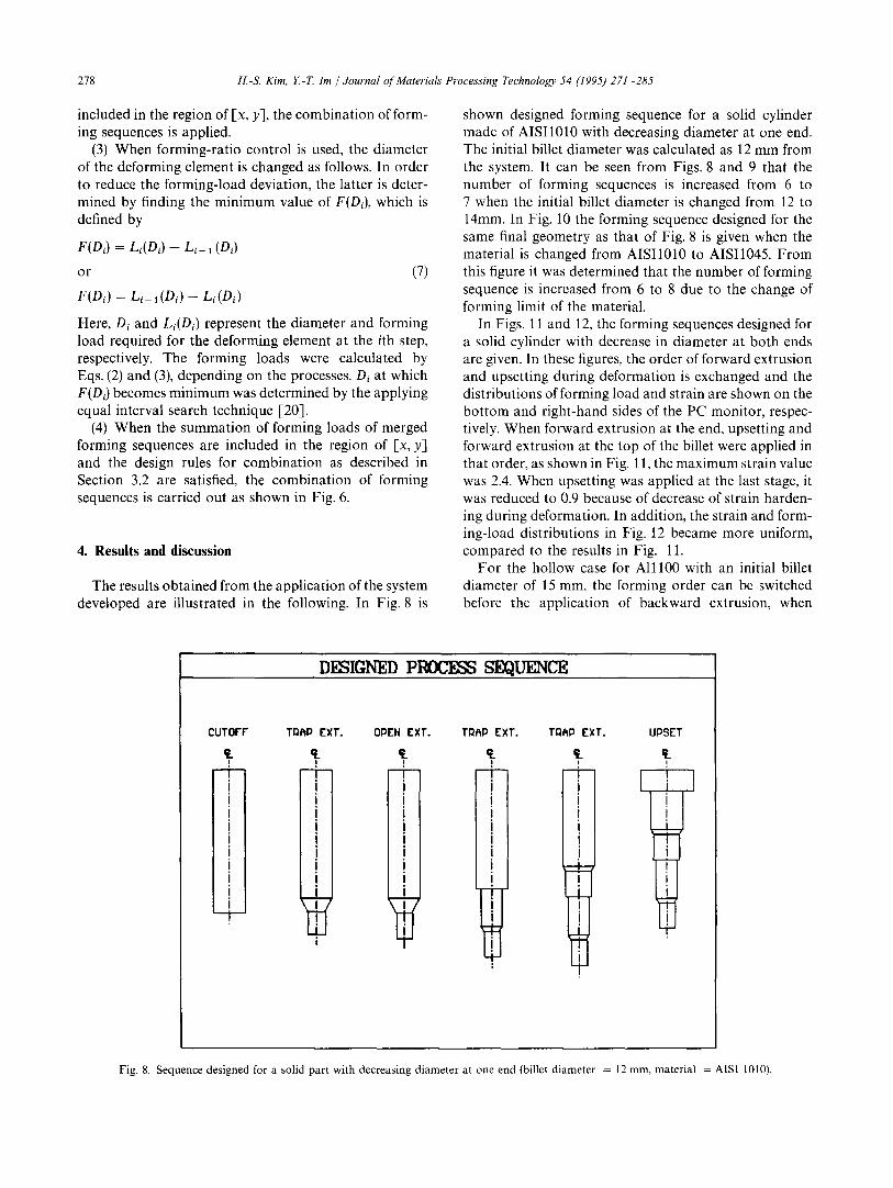
The results obtained from the application of the system developed are illustrated in the following. In Fig. 8 is
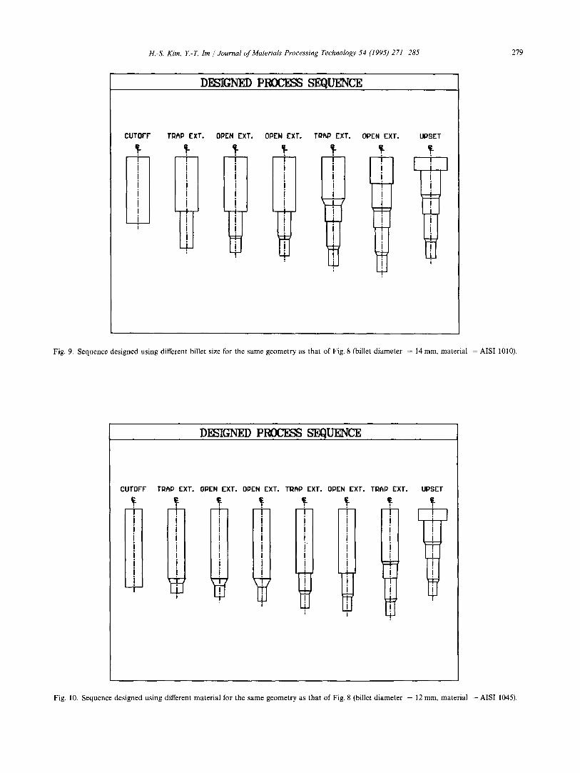
shown designed forming sequence for a solid cylinder made of AISI1010 with decreasing diameter at one end. The initial billet diameter was calculated as 12 mm from the system. It can be seen from Figs. 8 and 9 that the number of forming sequences is increased from 6 to 7 when the initial billet diameter is changed from 12 to 14mm. In Fig. 10 the forming sequence designed for the same final geometry as that of Fig. 8 is given when the material is changed from AISI1010 to AISI1045. From this figure it was determined that the number of forming sequence is increased from 6 to 8 due to the change of forming limit of the material.
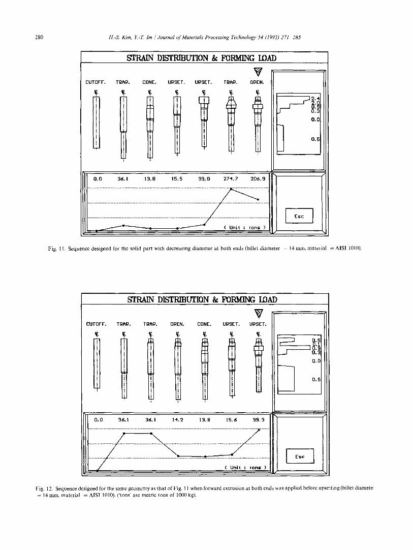
In Figs. 11 and 12, the forming sequences designed for a solid cylinder with decrease in diameter at both ends are given. In these figures, the order of forward extrusion and upsetting during deformation is exchanged and the distributions of forming load and strain are shown on the bottom and right-hand sides of the PC monitor, respec- tively. When forward extrusion at the end, upsetting and forward extrusion at the top of the billet were applied in that order, as shown in Fig. 11, the maximum strain value was 2.4. When upsetting was applied at the last stage, it was reduced to 0.9 because of decrease of strain harden- ing during deformation. In addition, the strain and form- ing-load distributions in Fig. 12 became more uniform, compared to the results in Fig. 11.
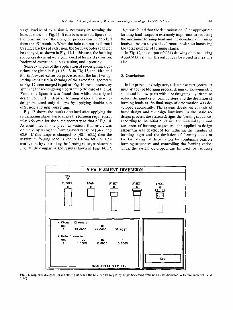
For the hollow case for Al l l00 with an initial billet diameter of 15 mm, the forming order can be switched before the application of backward extrusion, when
DESIGNED P ~ SEQUENCE
CUTOFF TQ~P EXT.
! ! I o
I I '
I m a
I !
W I
OPEN EXT. T~P EXT. T~P EXT.
" - -F
J I I i ! l ! I
I I
i
1
UPS[T
Fig. 8. Sequence des igned for a sol id p a r t w i th dec r ea s ing d i a m e t e r a t one end (billet d i a m e t e r = 12 m m , ma te r i a l = AISI 1010).
H.-S. Kim, Y.-T, Im / Journal of Materials Processing Technology 54 (1995) 271 285 279
DESIGNED P ~ S - ~ U I ~ C ~
CUTOFF TI~RP EXT. OPEN EXT. OPEN EXT. TDRP EXT. OPEN EXT. UPSET
Fig. 9. Sequence designed using different billet size for the same geometry as that of Fig. 8 (billet diameter = 14 mm, material = AISI 1010).
DESIGNED P l ~ C I ~ S ~ U ~ C E
CUTOFF
- F
I ! I
, i I
TI:;IhP EXT.
,
I I ! I
I
!
OPEN EXT.
i I I ! I i
i
OPEN EXT. TI~RP EXT. OPEN EXT. T~RP EXT.
I I
! I
!
T i
i-
t I
i
! I
'i
UPSET
]
I I I
Fig. 10. Sequence designed using different material for the same geometry as that of Fig. 8 (billet diameter = 12 mm, material = AISI 1045).
280 H.-S. Kim, E-T. Im / Journal of Materials Processing Technology 54 (1995) 271-285
STRAIN DISTRIBUTION & FORMING lOAD
UTOFF.
T i i
I i I
2
TR~P. CONE.
I
t I
I :I= i
I
it
UPSET.
II II II II
UPSET. TRAP. OPEN.
i
2.'1
0.3 0.(~
O,E
0.0 36.1 13.8 15.5 39.0 274.7 206.9
( Uni~ : tons )
I ' Esc I 1 i
Fig. 11. Sequence designed for the solid part with decreasing diameter at both ends (billet diameter = 14 mrn~ material = AISI 1010).
S T _ ~ ~ DISTRIBUTION & FORMING LOAD
V CUTOFF. TRAP. TRAP.
I I ! I I i I I
"1"
i I
I I
I
I i
I ! I i + i I $
i
OPEN.
i I i
I i I !
I
CONE.
i ! t
I
I
i I I T
UPSET.
t
i
I
I ?
UPSET.
W
O.
o.
l l....~:. °. ......... .3...'-i ........... ~:~. .......... ,'.i~. .......... ~.?:.~ .......... i.'. .......... .37~...
i Esc [
Fig. 12. Sequence designed for the same geometry as that of Fig. 11 when forward extrusion at both ends was applied before upsetting (billet diamete~ = 14 mm, material = AISI 1010). ('tons' are metric tons of 1000 kg).
H.-S. Kim, Y-T. Im /Journal of Materials Processing Technology 54 (1995) 271-285 281
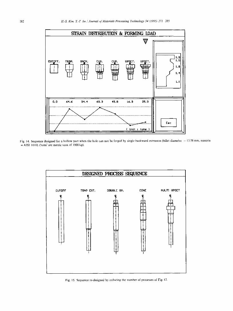
single backward extrusion is necessary in forming the hole, as shown in Fig. 13. It can be seen in this figure that the dimensions of the designed process can be checked from the PC monitor. When the hole can not be formed by single backward extrusion, the forming orders can not be changed, as shown in Fig. 14. In this case, the forming sequences designed were composed of forward extrusion, backward extrusion, cup extrusion, and upsetting.
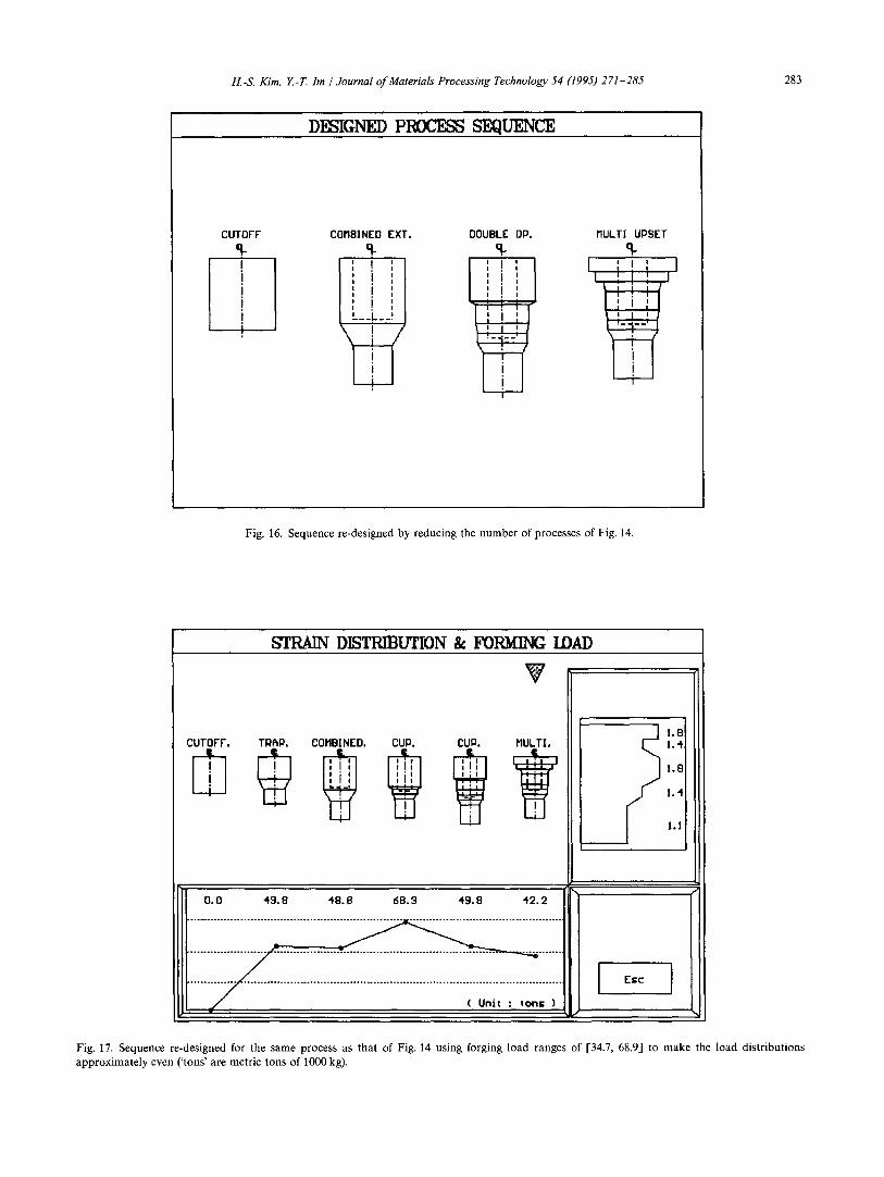
Some examples of the application of re-designing algo- rithms are given in Figs. 15-18. In Fig. 15, the third and fourth forward extrusion processes and the last two up- setting steps used in forming of the same final geometry of Fig. 12 were merged together. Fig. 16 was obtained by applying the re-designing algorithm to the case of Fig. 14. From this figure it was found that whilst the original design required 7 steps of forming stages the new re- design required only 4 steps by applying double cup extrusion and multi-upsetting.
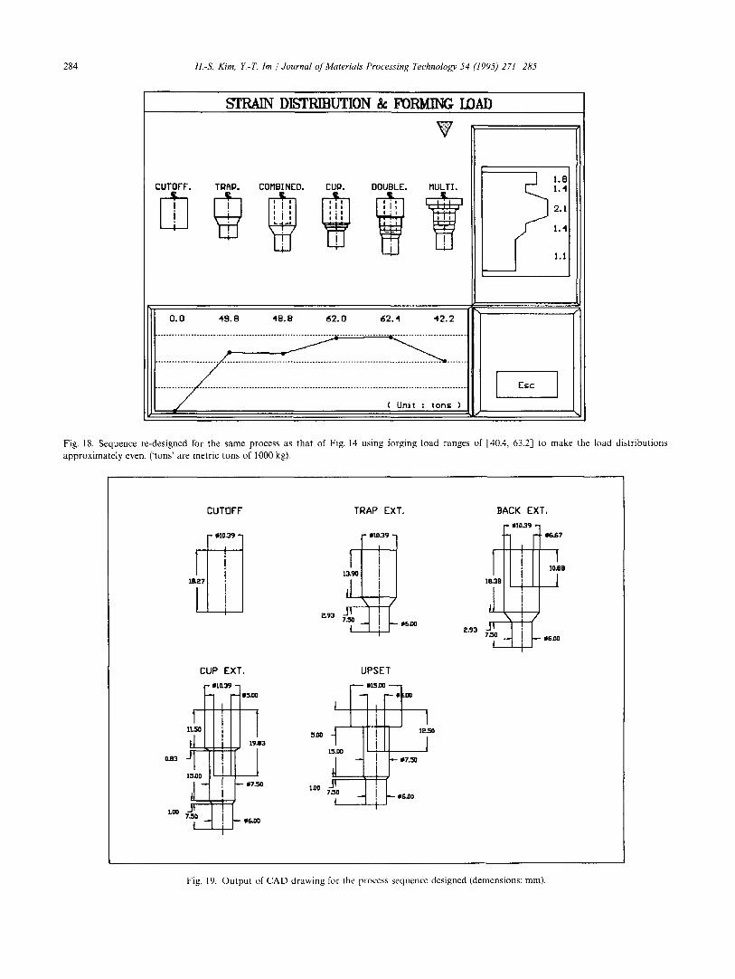
Fig. 17 shows the results obtained after applying the re-designing algorithm to make the forming requirement relatively even for the same geometry as that of Fig. 14. As mentioned in the previous section, this result was obtained by using the forming-load range of [34.7, and 68.9]. If this range is changed to [40.4, 63.2] then the maximum forging load is reduced from 68.3 to 62.4 metric tons by controlling the forming ratios, as shown in Fig. 18. By comparing the results shown in Figs. 14, 17,
18, it was found that the determination of the appropriate forming load ranges is extremely important in reducing the maximum forming load and the deviation of forming loads at the last stages of deformation without increasing the total number of forming stages.
In Fig. 19, the output of CAD drawing obtained using AutoCAD is shown: the output can be stored in a text file also.
5. Conclusions
In the present investigation, a flexible expert system for multi-stage cold-forging process design of axi-symmetric solid and hollow parts with a re-designing algorithm to reduce the number of forming steps and the deviation of forming loads at the final stage of deformation was de- veloped successfully. The system developed consists of basic design and re-design functions. In the basic re- design process, the system designs the forming sequences according to the initial billet size and material type, and the order of forming sequences. The applied re-design algorithm was developed for reducing the number of forming steps and the deviation of forming loads at the last stages of deformation by combining feasible forming sequences and controlling the forming ratios. Thus, the system developed can be used for reducing
VIEW k ~ ~ DIMENSION
CUTOFF. TQ~P. UPSET. UPSET.
i i l_C.J I I
l =r !I !i i i J; !i i~ i j!
I I . I " f - '
B~CK.
I i 1
Element Oimension
No. 00 O! H I 15.0000 15.0000 35. B027
Hole Dimension No. 00 0! H
I 0.0000 0.0000 O. O000
Quit: Prexx ~E~c J keu
Esc
Fig. 13. Sequence designed for a hollow part when the hole can be forged by single backward extrusion (billet diameter = 15 mm, material = AI 1100).
282 H.-S. Kim, Y.-T. Im / Journal of Materials Processing Technology 54 (1995) 271 285
STRAIN DISTRIBUTION & FORMING IDAD
BACK. ~ UPSET.
l l....~:.°.. ......... J~:.~ .......... ~7.:~ .......... ~.~.3 .......... 7.72 .......... i.~.:~ .......... ~:.~...
~ l .B 1.5
l.B J f 1,4
1,1
I E=c I
Fig. 14. Sequence designed for a hollow part when the hole can not be forged by single backward extrusion (billet diameter = 13.58 mm, materia
= AISI 1010). ( 'tons' are metric tons of 1000 kg).
DESIGNED P ~ S~UENCE
CUTOFF
! T i I i I I i i I i I +
TRAP EXT. DOUBLE OP. CONE
"]-
i I i i I i I
+ ! I
I I
I
!
I
MULTI UPSET
T
i l m
T L
T I ! I i I
Fig. 15. Sequence re-designed by reducing the number of processes of Fig. 12.
H.-S. Kim, Y.-T. lm / Journal of Materials Processing Technology 54 (1995) 271-285 283
DESIGNED PNOCE~ SEQUENCE
CUTOFF COMBINEO EXT. 9-
i(
OOUBLE OP. o
MULTI UPSET °r
?
Fig. 16. Sequence re-designed by reducing the number of processes of Fig. 14.
8'I'RAIN DISTRIBUTION &: FORMING IDA/)
V
CUTOFF. TRAP. COMBINED, CUP. CUP. MULTI.
0 . 0 4 '9 .8 4 8 . 8 6 8 . 3 4 '9 .8 4 '2 .2
~ l .B ! .4
I.B
1.4
1.1
I E=c I
Fig. 17. Sequence re-designed for the same process as that of Fig. 14 using forging load ranges of [34.7, 68.9] to make the load distributions approximately even ('tons' are metric tons of 1000 kg).
284 H.-S. Kim, E-Z hn / Journal o/'Materials Processing Technology 54 (1995) 271 285
STRAIN DISTRIBUTION & FORMING LOAD
V
CUTOFF. TRf~P. COMBINED. CUP. DOUBLE. MULTI. ~ 1.8 1.4
2.1
1.4
_ _ l 1.1
O.O 4 9 . 8 4 8 . 8 6 2 . 0 6 2 . 4 4'2 .2
iiii i;;;iiiiiiiiiiiiiiiiil;;;;iii!~:~::~:iiiiii~iiiiiii~ ..... ~ i . . . . . . . . . . . . . . . . . ~ ~:;i:~:; I~:
Fig. 18. Sequence re-designed for the same process as that of Fig. 14 using forging load ranges of [40.4, 63.2] to make the load distributions approximately even. ('tons' are metric tons of 1000 kg).
CUTOFF
CUP EXT,
! o
i
°" !oi~ f
l,OO
i m5,oo
19.B3
.,! - g6.00
TRAP EXT.
I .'°3" ] 13,90
,1 a93 - ~ - - /
~.oo t 15,00
,1
UPSET
II', IE,..~
1 F ~7,50
BACK EXT,
IO.8B
~ B J
P.93 iIr;.O0
Fig. 19, Output of CAD drawing for lhe process sequence designed (demensions: mm).
H.-S. Kim, E-T. I m / Journal of Materials Processing Technology 54 (1995) 271 285 285
trial-and-error by design engineers in determining the diameter and height of the initial cylindrical billet from the final product geometry and the intermediate neces- sary sequences. In order to improve the usage of the program developed, accumulation of various rule-bases and material data-bases by interview of design engineers is beneficial.
Acknowledgements
The authors wish to thank the Ministry of Science & Technology and the Jinhap Forging Company for their grants which made this work possible.
References
[1] B. W. Niebel, J. Ind. Eng., 17 (1966) 598-603. [2] A. J. Barker, Machinery and Production Eng. (1968) 268-277 [3] N. Akgerman and T. Altan, Recent developments in computer-
aided design of forging processes, SME Technical Paper, MF72- 110, 1972.
[4] S. K. Biswas and W. A. Knight, Proc. 15th Int. Machine Tool Design and Research Conf., Birmingham, Macmillan, London, 1974, pp. 135-143.
[5] M. I. Gokler T. A. Dean and W. A. Knight, Proc. l l th North American Manufacturing Research Conf., 1983, pp. 217 223.
[6] A. A. Badawy, P. S. Raghupathi, D. J. Kuhlmann and T. Altan, J. Mech. Work. Tech., 11 (1985) 259 274.
[7] P. Bariani, E. Benuzzi and W. A. Knight, Ann. CIRP, 36 (1987) 145 148.
[8] K. Sevenler, P. S. Raghupathi, and T. Altan, J. Mech. Work. Tech., 14 (1987) 121 135.
[9] W. Makosch and K. Lange, Proc. 16th North American Manufac- turing Research Con[i 1988, pp. 63 70.
[10] P. Bariani, G. Berti, L. D'angelo, M. Marengo and A. Rossi, Adv. Technol. Plasticity, 1 (1990) 7-12.
[11] G. Yang and K. Osakada, Adv. Technol. Plasticity, 1 (1990) 109-114.
[12] H. K. Kim and T. Altan, J. Mater. Process. Technol., 33 (1992) 57 74.
[13] R. Maus and J. Keyes, Handbook Of Expert Systems in Manufac- turing, McGraw-Hill, New York, 1991.
[14] M. M. Nelson and W. T. Illingworth, A Practical Guide to Neural Nets, Addison-Wesley, Reading, MA, 1990.
[15] L. A. Zadeh, Inform. and Control, 8 (1965) 338 353. [16] B. Buchanan and E. Feigenbaum, Artif. Intelligence , 11 (1978)
5-24. [17] K. Lange, Handbood of Metal Forming, McGraw-Hill, New York,
1985. [18] National Machinery Company, Tool Design and Part Shape
Development for Multi-Die Cold Forming, Tiffin, OH, 1985. [19] T. Altan, S. I. Oh and H. L. Gegel, Metal Forming: Fundamentals
and Applications, American Society for Metals, Metal Park, Ohio, 1983.
[20] J. S. Arora, Optimum Design, McGraw-Hill, Singapore, 1989.