Embed Size (px)
Citation preview

1
NC Wall Bracing Proposal for Permanent Rule – Rules Commission Submittal ‐ 01/04/13
Explanation of proposal:
1. Section R602.10 ‐‐ provides charging language for two simplified bracing approaches (isolated
panel and continuously sheathed), an engineered approach, and the IRC 2012 provisions.
2. Section R602.10.1 – provides bracing methods and materials common to both simplified
methods and is non‐exclusive. [ 2 paragraphs, 1 Table]
3. Section R602.10.2 – simplified isolated panel bracing (for low wind only, 90 and 100 mph) [1
page including Table]
4. Section R602.10.3 – simplified continuous bracing (for up to 110 mph, wind); this could be
expanded to match other NC proposals to 130 mph or decreased to match VA proposal to 100
mph; otherwise very similar; any of the NC proposals could be substituted in this section if
desired [3‐1/2 pages including Table and Figures]
5. Section R602.10.4 – provides engineering approach that would be applicable to any wind zone
within scope; provides means of engineering consistent with IRC bracing provisions to promote
competitive value of engineered solutions in a manner exactly equivalent to the IRC; this could be
a very efficient means of addressing the 110‐130 mph range in NC. [1 paragraph]
6. Section R602.10.5 – provides various load path details important to overall building performance
and connectivity for any bracing method.[3 pages including text, figures, and table]
7. REASON STATEMENT – at end of proposal.
Proposal:
R602.10 Wall bracing. Buildings, and portions thereof, shall be braced in accordance with one or more of the following sections using bracing materials and methods complying with Section R602.10.1 and load path detailing in accordance with Section R602.10.5:
1. Isolated panel bracing per Section R602.10.2, 2. Continuous sheathing per Section R602.10.3, 3. Engineered design per Section R602.10.4, or 4. 2012 International Residential Code (IRC). 5. SR-102 as published by APA, The Engineered Wood Association with limitations indicated in
this document. Note: Code references in SR-102 are referencing the 2012 IRC. Where a building, or portion thereof, does not comply with Section R602.10.2, Section R602.10.3, or Section R602.10.5, those portions shall be designed and constructed in accordance with Section R602.10.4. R602.10.1 Bracing materials and methods. Wall bracing materials and methods shall comply with Table R602.10.1.

2
Table R602.10.1 BRACING METHODS1, 2
Method Minimum Brace Material Thickness or Size
Minimum Brace Panel Length or Brace Angle
Connection Criteria Fasteners Spacing
LIB Let-in Bracing
1x4 wood brace (or approved metal brace installed per manufacturer instructions)
45o angle for maximum 16”oc stud spacing3
2-8d common nails or 3-8d (2-1/2” long x 0.113” dia.) nails
Per stud and top and bottom plates
DWB Diagonal wood boards
¾” (1” nominal) 48” 2-8d (2-1/2” long x 0.113” diameter) or 2 – 1-3/4” long staples
Per stud and top and bottom plates
WSP Wood structural panel
3/8” 48”4 6d common nail or 8d (2-1/2” long x 0.113” diameter) nail
6” edges 12” field
SFB Structural Fiberboard Sheathing
½” 48”4 1-1/2” long x 0.120” dia. Galvanized roofing nails
3” edges 6” field
GB Gypsum Board Installed on both sides of wall
½” 96” for use with R602.10.2 48” for use with R602.10.3
Min. 5d cooler nails or #6 screws
7” edges 7” field
PCP Portland cement plaster
¾” (maximum 16”oc stud spacing)
48” 1-1/2” long, 11 gage, 7/16” diameter head nails or 7/8” long, 16 gage staples
6” o.c. on all framing members
CS-WSP5 Continuously sheathed WSP
3/8” 24” adjacent to window not more than 67% of wall height; 30” adjacent to door or window greater than 67% and less than 85% of wall height. 48” for taller openings.
Same as WSP Same as WSP
CS-SFB5 Continuously sheathed SFB
½” Same as SFB Same as SFB
PF Portal Frame6
7/16” See Figure R602.10.1
See Figure R602.10.1
See Figure R602.10.1
Table Notes: 1. Alternative bracing materials and methods shall comply with Section 105 of the North Carolina Administrative Code
and Policies, and shall be permitted to be used as a substitute for any of the bracing materials listed in Table R602.10.1 provided at least equivalent performance is demonstrated. Where the tested bracing strength or stiffness differs from tabulated materials, the bracing amount required for the alternative material shall be permitted to be factored to achieve equivalence.
2. All edges of panel-type wall bracing shall be attached to framing or blocking, except GB bracing horizontal joints shall not be required to be blocked when joints are finished.
3. Two LIB braces installed at a 60o angle shall be permitted to be substituted for each 45o angle LIB brace. 4. For 8-foot or 9-foot wall height, brace panel minimum length shall be permitted to be reduced to 36-inch or 42-inch
length, respectively, where not located adjacent to a door opening. A braced wall panel shall be permitted to be reduced to a 32-inch length when studs at each end of the braced wall panel are anchored to foundation or framing below using hold-down device with minimum 2,800 lbs. design tension capacity. For detached single story garages

3
and attached garages supporting roof only, a minimum 24-inch brace panel length shall be permitted on one wall containing one or more garage door openings.
5. Bracing methods designated CS-xxx shall have sheathing installed on all sheathable surfaces above, below, and between wall openings.
6. For purposes of bracing in accordance with Section R602.10.2, two portal frame brace panels with wood structural panel sheathing applied to the exterior face of each brace panel as shown in Figure R602.10.1 shall be considered equivalent to one braced wall panel.
OVER CONCRETE OR MASONRY BLOCK FOUNDATION
WOOD STRUCTURALPANEL SHEATHINGCONTINUOUS OVER BANDOR RIM JOIST
OVER RAISED WOOD FLOOR - OVERLAP OPTION
FASTEN TOP PLATE TOHEADER WITH TWOROWS OF 16D SINKERNAILS AT 3" O.C. TYP.HEADER TO JACK-STUD STRAP ON BOTH SIDES
OF OPENING OPPOSITE SIDE OF SHEATHING;STRAP CAPACITY SHALL EQUAL 1,000 LBS. OR4,000 LBS. WHEN PONY WALL IS PRESENT
MIN. DOUBLE STUD FRAMING COVERED WITH MIN.7/16" THICK WOOD STRUCTURAL PANELSHEATHING WITH 8D COMMON OR GALVANIZEDBOX NAILS AT 3" O.C. IN ALL FRAMING (STUDS,BLOCKING, AND SILLS) TYP.
MINIMUM PANEL LENGTH
MIN. DOUBLE POST(KING AND JACK STUD).NUMBER OF JACKSTUDS PER TABLESR502.5(1) & (2).
MIN. (2) 1/2" DIAMETER ANCHOR BOLTSINSTALLED PER R403.1.6 WITH 3"x3"x3/16" PLATEWASHER
IF NEEDED PANELSPLICE EDGES SHALLOCCUR AND BEATTACHED TOCOMMON BLOCKINGWITHIN 24" OF WALLMID- HEIGHT. ONE ROWOF 3" O.C. NAILING ISREQUIRED IN EACHPANEL EDGE.
TYPICAL PORTALFRAME CONSTRUCTION
TENSION STRAP (ONOPPOSITE SIDE OFSHEATHING)
MIN. 3" X 11-1/4" NET HEADERSTEEL HEADER PROHIBITED
12'
MA
X T
OT
AL
WA
LL
HE
IGH
T
EXTENT OF HEADER WITH SINGLE PORTAL FRAME(ONE BRACED WALL PANEL)
10'
MA
X.
PA
NE
L H
EIG
HT
FASTEN SHEATHING TO HEADER WITH 8DCOMMON OR GALVANIZED BOX NAILS IN 3" GRIDPATTERN AS SHOWN
4' MAX PONYWALL HEIGHT
BRACED WALL LINECONTINUOUSLY SHEATHEDWITH WOOD STRUCTURALPANELS
ANCHOR BOLTS PERSECTION R403.1.6
EXTENT OF HEADER WITH DOUBLE PORTAL FRAMES (TWO BRACED WALL PANELS)
MIN. 7/16" WOODSTRUCTURAL PANELSHEATHING
NAIL SOLEPLATE TO JOISTPER TABLER602.3(1)
APPROVED BANDOR RIM JOIST
MIN
.O
VE
RLA
P9
-1/4
"
2' -18' FINISHED WIDTH OF OPENINGFOR SINGLE OR DOUBLE PORTAL
FRONT ELEVATION SECTION
NAIL SOLE PLATETO JOIST PERTABLE R602.3(1)
ATTACH SHEATHING TOBAND OR RIM JOIST WITH8D COMMON NAILS AT 3"O.C. TOP AND BOTTOM
WALL HEIGHT, ft. 8 9 10 11 12
PANEL LENGTH, in. 16 18 20 22 24
MIN. 2X4 STUDS WITHPONY WALL HEIGHT UP TO2'; MIN. 2X6 STUDS WITHPONY WALL HEIGHTGREATER THAN 2'.
WOOD STRUCTURAL PANELSHEATHING TO TOP OF BAND ORRIM JOIST
NAIL SOLEPLATE TO JOISTPER TABLER602.3(1)
APPROVED BANDOR RIM JOIST
NAIL SOLE PLATETO JOIST PERTABLE R602.3(1)
OVER RAISED WOOD FLOOR - FRAMING ANCHOR OPTION
(2) FRAMING ANCHORSAPPLIED ACROSSSHEATHING JOINT WITH ACAPACITY OF 670 LBS INTHE HORIZONTAL ANDVERTICAL DIRECTIONS
WOOD STRUCTURAL PANELSHEATHING OVERAPPROVED BAND OR RIMJOIST
WOOD STRUCTURAL PANELSHEATHING OVERAPPROVED BAND OR RIMJOIST
For SI: 1 inch = 25.4 mm, 1 foot = 305 mm, 1 lb = 4.45 N Figure R602.10.1
Method PF – Portal Frame Construction
ICC Staff: On middle illustration above remove the word “VERTICAL” from the note referring to the (2) framing anchors.
4
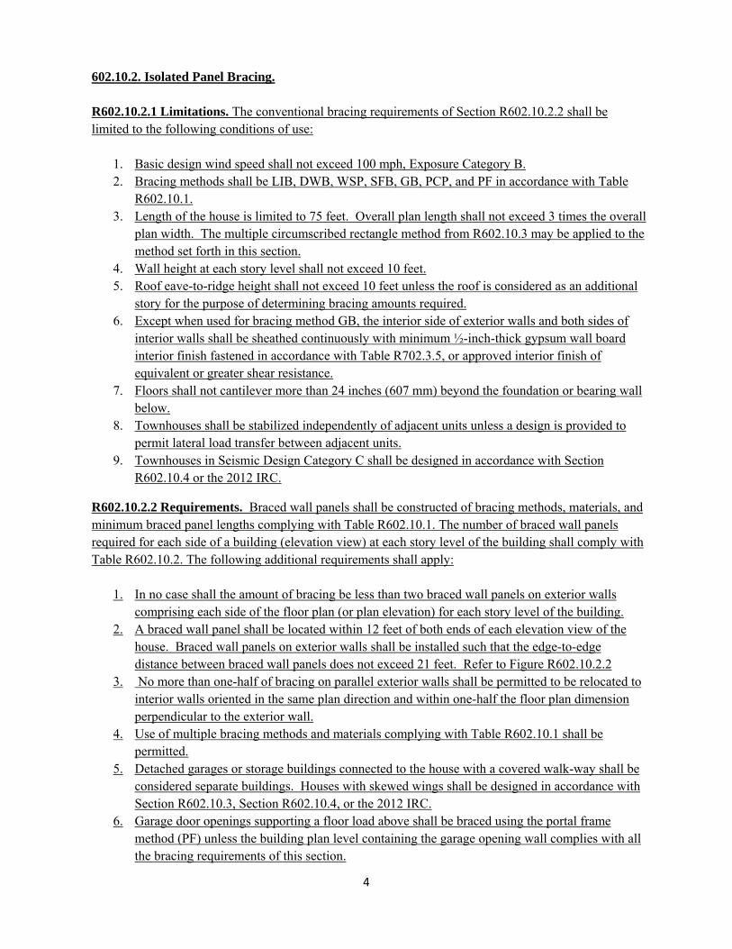
602.10.2. Isolated Panel Bracing. R602.10.2.1 Limitations. The conventional bracing requirements of Section R602.10.2.2 shall be limited to the following conditions of use:
1. Basic design wind speed shall not exceed 100 mph, Exposure Category B. 2. Bracing methods shall be LIB, DWB, WSP, SFB, GB, PCP, and PF in accordance with Table
R602.10.1. 3. Length of the house is limited to 75 feet. Overall plan length shall not exceed 3 times the overall
plan width. The multiple circumscribed rectangle method from R602.10.3 may be applied to the method set forth in this section.
4. Wall height at each story level shall not exceed 10 feet. 5. Roof eave-to-ridge height shall not exceed 10 feet unless the roof is considered as an additional
story for the purpose of determining bracing amounts required. 6. Except when used for bracing method GB, the interior side of exterior walls and both sides of
interior walls shall be sheathed continuously with minimum ½-inch-thick gypsum wall board interior finish fastened in accordance with Table R702.3.5, or approved interior finish of equivalent or greater shear resistance.
7. Floors shall not cantilever more than 24 inches (607 mm) beyond the foundation or bearing wall below.
8. Townhouses shall be stabilized independently of adjacent units unless a design is provided to permit lateral load transfer between adjacent units.
9. Townhouses in Seismic Design Category C shall be designed in accordance with Section R602.10.4 or the 2012 IRC.
R602.10.2.2 Requirements. Braced wall panels shall be constructed of bracing methods, materials, and minimum braced panel lengths complying with Table R602.10.1. The number of braced wall panels required for each side of a building (elevation view) at each story level of the building shall comply with Table R602.10.2. The following additional requirements shall apply:
1. In no case shall the amount of bracing be less than two braced wall panels on exterior walls comprising each side of the floor plan (or plan elevation) for each story level of the building.
2. A braced wall panel shall be located within 12 feet of both ends of each elevation view of the house. Braced wall panels on exterior walls shall be installed such that the edge-to-edge distance between braced wall panels does not exceed 21 feet. Refer to Figure R602.10.2.2
3. No more than one-half of bracing on parallel exterior walls shall be permitted to be relocated to interior walls oriented in the same plan direction and within one-half the floor plan dimension perpendicular to the exterior wall.
4. Use of multiple bracing methods and materials complying with Table R602.10.1 shall be permitted.
5. Detached garages or storage buildings connected to the house with a covered walk-way shall be considered separate buildings. Houses with skewed wings shall be designed in accordance with Section R602.10.3, Section R602.10.4, or the 2012 IRC.
6. Garage door openings supporting a floor load above shall be braced using the portal frame method (PF) unless the building plan level containing the garage opening wall complies with all the bracing requirements of this section.

5
TABLE R602.10.2 Number of Braced Wall Panels Required
for Each House Elevation (Building Side) at Each Story Level1
1. Interpolation between dimensions is permitted. Extrapolation is prohibited. 2. Fractions of panels shall be rounded to the nearest whole panel.
Figure R602.10.2.2
Location of Braced Wall Panels
602.10.3 Continuous Sheathing.
R602.10.3.1 Limitations. The continuous sheathing requirements of Section R602.10.3 shall be limited to bracing methods CS-WSP and CS-SFB in accordance with Table R602.10.1 with the following conditions of use:
1. Basic design wind speed shall not exceed 110 mph. 2. Wall height at each story level shall not exceed 12 feet. 3. Eave to ridge height shall not exceed 20 feet. 4. Exterior walls shall be sheathed on all sheathable surfaces including infill areas between braced
wall panels, above and below wall openings, and on gable end walls. 5. Except when used for bracing method GB, the interior side of exterior walls and both sides of
interior walls shall be sheathed continuously with minimum ½-inch-thick gypsum wall board interior finish fastened in accordance with Table R702.3.5, or approved interior finish of
Wind Velocity Story Level Supporting:
Longest Overall Dimension of Floor Plan for a Given Story Level
25’ 50’ 75’ 90 mph Roof Only 1 2 3
Roof + 1 Story 2 4 6 Roof + 2 Stories 3 6 9
100 mph Roof Only 2 3 4 Roof + 1 Story 3 5 8 Roof + 2 Stories 4 8 11

6
equivalent or greater shear resistance Unless required for fire separation by Section R302.6, gypsum board shall be permitted to be omitted where the required length of bracing, as determined in Table R602.10.3, is multiplied by 1.40.
6. Floors shall not cantilever more than 24 inches (607 mm) beyond the foundation or bearing wall below.
7. Townhouses in Seismic Design Category C shall be designed in accordance with Section R602.10.4 or the 2012 IRC.
8. Townhouses shall be stabilized independently of adjacent units, unless a design is provided to permit lateral load transfer between adjacent units.
R602.10.3.2 Requirements. The required length of bracing for each side of a rectangle circumscribed around the plan or a portion of the plan at each story level shall be determined using Table R602.10.3 and Figure R602.10.3(1). The cumulative contributing length of braced wall panels assigned to a rectangle side shall be greater than or equal to the required length of bracing specified in Table R602.10.3. The following additional requirements shall apply.
1. Braced wall panels on exterior or interior walls shall be assigned to the nearest rectangle side as shown in Figure R602.10.3(2) for each story level floor plan.
2. Braced wall panels shall be distributed and installed in accordance with Figure R602.10.3(3). 3. A minimum of one-half the required bracing amount for each rectangle side should be located
on exterior walls within 8 feet of the location of the rectangle side. 4. Interior braced wall panels using Method GB shall be assigned to the closest parallel rectangle
side and shall contribute 0.5 times their actual length. 5. The bracing amount provided on an upper story building side shall be “deemed-to-comply”
where it equals or exceeds the amount of bracing required for the story immediately below. 6. Where the bracing amount provided on an upper story equals or exceeds the amount of bracing
required for the story below an analysis of bracing shall not be required for the upper story.
OR=ONE RECTANGLE TWO RECTANGLES
FIGURE R602.10.3(1)
CIRCUMSCRIBED RECTANGLES1,2,3
Figure Notes: 1. Each floor plan level shall be circumscribed with one or more rectangles around the floor plan or
portions of the plan at the floor level under consideration as shown in Figure R602.10.3(1). 2. Rectangles shall surround all enclosed offsets and projections such as sunrooms and attached garages
for a given story level floor plan. Chimneys, partial height projections, and open structures, such as carports and decks, shall be excluded from the rectangle.
3. Each rectangle shall have no side greater than 80 feet (24.4 m) with a maximum rectangle length-to-width ratio of 3:1. Rectangles shall be permitted to be skewed to accommodate diagonal walls.
7
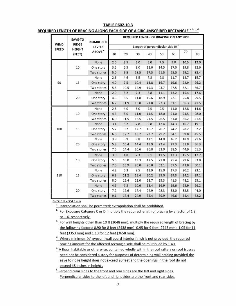
TABLE R602.10.3
REQUIRED LENGTH OF BRACING ALONG EACH SIDE OF A CIRCUMSCRIBED RECTANGLE a, b, c, d
WIND
SPEED
EAVE‐TO
RIDGE
HEIGHT
(FEET)
NUMBER OF
LEVELS
ABOVE e
REQUIRED LENGTH OF BRACING ON ANY SIDE
Length of perpendicular side (ft)f
10 20 30 40 50 60 70
80
90
10
None 2.0 3.5 5.0 6.0 7.5 9.0 10.5 12.0
One story 3.5 6.5 9.0 12.0 14.5 17.0 19.8 22.6
Two stories 5.0 9.5 13.5 17.5 21.5 25.0 29.2 33.4
15
None 2.6 4.6 6.5 7.8 9.8 11.7 13.7 15.7
One story 4.0 7.5 10.4 13.8 16.7 19.6 22.9 26.2
Two stories 5.5 10.5 14.9 19.3 23.7 27.5 32.1 36.7
20
None 2.9 5.2 7.3 8.8 11.1 13.2 15.4 17.6
One story 4.5 8.5 11.8 15.6 18.9 22.1 25.8 29.5
Two stories 6.2 11.9 16.8 21.8 27.3 31.1 36.3 41.5
100
10
None 2.5 4.0 6.0 7.5 9.5 11.0 12.8 14.6
One story 4.5 8.0 11.0 14.5 18.0 21.0 24.5 28.0
Two stories 6.0 11.5 16.5 21.5 26.5 31.0 36.2 41.4
15
None 3.4 5.2 7.8 9.8 12.4 14.3 16.7 19.1
One story 5.2 9.2 12.7 16.7 20.7 24.2 28.2 32.2
Two stories 6.6 12.7 18.2 23.7 29.2 34.1 39.8 45.5
20
None 3.8 5.9 8.8 11.1 14.0 16.2 18.9 21.6
One story 5.9 10.4 14.4 18.9 23.4 27.3 31.8 36.3
Two stories 7.5 14.4 20.6 26.8 33.0 38.5 44.9 51.3
110
10
None 3.0 4.8 7.3 9.1 11.5 13.3 15.5 17.7
One story 5.5 10.0 13.3 17.5 21.8 25.4 29.6 33.8
Two stories 7.5 13.9 20.0 26.0 32.1 37.5 43.8 50.1
15
None 4.2 6.3 9.5 11.9 15.0 17.3 20.2 23.1
One story 6.3 11.2 15.4 20.2 25.0 29.3 34.2 39.1
Two stories 8.0 15.4 22.0 28.7 35.3 41.3 48.2 55.1
20
None 4.6 7.2 10.6 13.4 16.9 19.6 22.9 26.2
One story 7.2 12.6 17.4 22.9 28.3 33.0 38.5 44.0
Two stories 9.1 17.4 24.9 32.4 39.9 46.6 54.4 62.2
For SI: 1 ft = 304.8 mm a. Interpolation shall be permitted; extrapolation shall be prohibited. b. For Exposure Category C or D, multiply the required length of bracing by a factor of 1.3
or 1.6, respectively. c. For wall heights other than 10 ft (3048 mm), multiply the required length of bracing by
the following factors: 0.90 for 8 feet (2438 mm), 0.95 for 9 feet (2743 mm), 1.05 for 11
feet (3353 mm) and 1.10 for 12 feet (3658 mm). d. Where minimum ½” gypsum wall board interior finish is not provided, the required
bracing amount for the affected rectangle side shall be multiplied by 1.40. e. A floor, habitable or otherwise, contained wholly within the roof rafters or roof trusses
need not be considered a story for purposes of determining wall bracing provided the
eave to ridge height does not exceed 20 feet and the openings in the roof do not
exceed 48 inches in height . f. Perpendicular sides to the front and rear sides are the left and right sides.
Perpendicular sides to the left and right sides are the front and rear sides.

8
+= RECTANGLE 1
REAR SIDE 1
LE
FT
SID
E 1
FRONT SIDE 2
RIG
HT
SID
E 2
RECTANGLE 2
COMMONRECTANGLESIDES
ADD CONTRIBUTING LENGTHSOF BRACED WALL PANELSASSIGNED TO A RECTANGLESIDE
ASSIGN PROJECTED CONTRIBUTINGLENGTHS OF ANGLED BRACED WALLPANELS TO ADJACENT RECTANGLESIDES
(a) Regular Floor Plan
FIGURE R602.10.3(2)a
RECTANGLE 1
RECTANGLE 2
PROJECTIONS APPLY TOSIDES OF RECTANGLE 1
CONTRIBUTING LENGTH OFBRACED WALL PANEL APPLIESTO SIDE OF RECTANGLE 2
=
(b) Skewed Floor Plan
FIGURE R602.10.3(2)b

9
FIGURE R602.10.3(2)c
FIGURE R602.10.3(2) Notes
ASSIGNMENT OF BRACED WALL PANELS TO CIRCUMSCRIBED RECTANGLE SIDES1,2,3,4,5,6
Figure Notes: 1. Exterior braced wall panels shall be assigned to the closest parallel rectangle side and shall contribute
their actual length. 2. Interior braced wall panels using Method GB shall be assigned to the closest parallel rectangle side and
shall contribute 0.5 times their actual length. 3. Projected contributing lengths of angled braced wall panels shall be assigned to the closest rectangle
sides. 4. Portal frame braced wall panels shall contribute 1.5 times their actual length to their assigned rectangle
side. 5. Where multiple rectangles share a common side or sides, as shown in Figure R602.10.3(2)(a), the
required length of bracing shall equal the sum of the required lengths from each of the shared rectangle sides.
6. Braced wall panels located on a common wall where skewed rectangles intersect, as shown in Figure R602.10.3(2)(b), shall have their contributing length applied towards the required length of bracing for the parallel rectangle side and its projected contributing lengths towards the adjacent skewed rectangle sides. Where the common side of rectangle 2 as shown in Figure R602.10.3(2)c has no physical wall, the wall bracing required to stabilized this side of Rectangle 2 shall be determined from Table 602.10.3. This length of bracing shall be resolved into orthogonal projections, and the orthogonal projections shall be added to the length of bracing required for the walls of Rectangle 1 which connect to Rectangle 2 in the directions parallel to the projections.

10
For SI: 1 ft = 304.8 mm
FIGURE R602.10.3(3)
DISTRIBUTION OF BRACED WALL PANELS1,2,3,4,5
Figure Notes: 1. A braced wall panel shall be located on each elevation view within 12 feet of the corners of
circumscribed rectangles. Detached garages or storage buildings connected to the house with a covered walk-way shall be considered separate buildings.
2. The distance between adjacent edges of braced wall panels shall be no more than 21 feet (6096 mm). 3. Segments of exterior walls greater than 12 feet (2438 mm) in length shall have a minimum of one
braced wall panel. 4. Segments of exterior wall 12 feet (2438 mm) or less in length shall be permitted to have no bracing
provided a braced wall panel is located within 12 feet from the rectangle corner. 5. Interior and exterior wall segments which contribute to the common sides of multiple rectangles shall
be permitted to apply the distribution requirements given above to each wall segment independently.

11
R602.10.4 Wall bracing by engineered design. Designs using bracing materials and methods listed in Table R602.10.1 or approved alternative materials and methods shall be permitted and shall comply with accepted engineering practice. Accepted engineering practice shall include the following:
1. Design in accordance with Section R301, 2. Design equivalent to the analysis basis of the provisions in Sections R602.10.2, R602.10.3, and
R602.10.5, including determination of design loads, design unit shear values, and bracing amounts1.
R602.10.5 Load path details. Construction shall comply with applicable detailing requirements of this section to ensure an adequate continuous load path for transfer of bracing loads and uplift loads from the roof to the foundation.
R602.10.5.1 Wind Uplift Load Path. Framing connections to transfer roof uplift forces shall comply with Section R602.3.5 and Section R802.11. In the 110 mph wind zone provide uplift anchorage in accordance with Sections R4508 and Section R4504.1.
R602.10.5.2 Foundation Anchorage. Braced wall panels shall be connected to the foundation per Section R403.1.6 and as required in Figure R602.10.1 for portal frames.
R602.10.5.3 Masonry or Concrete Pedestals. Masonry or concrete stem walls with a length of 48 inches (1220 mm) or less supporting braced wall panels shall be reinforced in accordance with Figure R602.10.4.3. Concrete stem walls shall be 6” nominal minimum thickness. Continuous concrete stem walls shall be reinforced per Section R404.1.2.2.
1 Contact NCDOI for information on the analysis basis for the wall bracing methods specified
in this section.

12
OPTIONAL STEM WALL REINFORCEMENT
TALL STEM WALL REINFORCEMENTSHORT STEM WALL REINFORCEMENT
24"
MA
X.
48"
MA
XIM
UM
48"
MA
XIM
UM
3" COVER
20" MIN. TYP.3" COVER3" COVER
6" M
IN.
6" M
IN.
8"
MIN
.
48" OR LESS
BRACED WALL PANEL
MIN. 2" CUT WASHERS
BOND BEAM NOT REQUIRED
#4 BAR
BOND BEAM
20"
LAP
, TY
P.
1/2" ANCHOR BOLTS PERBRACED WALL PANELREQUIREMENTS
BRACED WALL PANEL
20" MIN. TYP.
#4 BAR MIN.; FIELD BEND 6"EXTENSION INTO BOND BEAM
BOND BEAM WITH 1-#4 BAR
5/8" THREADED RODS MAY BESUBSTITUTED FOR ANCHORBOLTS AND REBAR
1/2" ANCHOR BOLTS PER BRACEDWALL PANEL REQUIREMENTS
#4 BAR
BRACED WALL PANEL
8" MIN. CMUFACE BRICKOPTIONAL
TYPICAL STEM WALL SECTION
BRACED WALLPANEL
BOND BEAM
NOTE: GROUT BOND BEAMS AND ALL CELLS WHICH CONTAINREBAR, THREADED RODS AND ANCHOR BOLTS.
48" OR LESS
48" OR LESS
RODS MAY BE INSTALLED USING AN ADHESIVE ANCHORING SYSTEM WITHA MINIMUM TENSILE CAPACITY OF 5,000 LBS AND INSTALLED INACCORDANCE WITH MANUFACTURER'S SPECIFICATIONS
For SI: 1 in=25.4 mm
FIGURE R602.10.5.3
MASONRY STEM WALLS SUPPORTING BRACED WALL PANELS
ICC Staff: In the lower left diagram change 5/8” threaded rods to ½” threaded rods, and change
adhesive capacity from 5000 lbs. to 3750 lbs.
R602.10.5.4 Blocking of floor framing. When parallel to floor framing, braced wall panels shall be connected to a band, rim or header joist, floor framing or perpendicular full-height solid blocking between floor framing at 16 inches (406 mm) on center. When perpendicular to floor framing, braced wall panels shall be connected to full-height solid blocking between floor framing. Attachments shall be in accordance with Table R602.3(1). Manufactured lumber or truss blocking panels shall be permitted to substitute for full-height solid blocking.
R602.10.5.5 Blocking of roof framing. When parallel to roof framing, braced wall panels shall be connected to a band, rim or header joist, or roof truss. When perpendicular to roof framing, the top

13
plates of exterior braced wall panels shall be connected to the rafters or roof trusses above in accordance with Table R602.10.5.5 and fastened in accordance with Table R602.3(1).
TABLE R602.10.5.5
BRACED WALL PANEL CONNECTIONS TO PERPENDICULAR ROOF FRAMING
DISTANCE FROM TOP OF BRACED WALL PANEL TO TOP
OF RAFTER OR ROOF TRUSS, (in)REQUIREMENT REFERENCED FIGURE
≤ 9.25 No blocking required NA 9.26 – 15.25 Solid 2x blocking between rafters or trusses R602.10.5.5(1) 15.26 – 48 Vertical blocking panels R602.10.5.5(2)
> 48 Designed in accordance with accepted
engineering practice NA
For SI: 1 inch = 25.4 mm
For SI: 1 inch = 25.4 mm
FIGURE R602.10.5.5(1)
BRACED WALL PANEL CONNECTION TO PERPENDICULAR RAFTERS OR TRUSSES
FIGURE R602.10.5.5(2)
BRACED WALL PANEL CONNECTION TO PERPENDICULAR RAFTERS OR ROOF TRUSSES
14
R602.10.5.6 Cripple walls and framed walls of walk-out basements. The required length of bracing for cripple walls with a maximum height of 48 inches (1220 mm) or less along its entire length shall be equal to the bracing provided for the wall above. The required length of bracing for cripple walls with a height greater than 48 inches (1220 mm) at any location along its length and for framed walls of a walk-out basement shall be determined in accordance with Section R602.10.2 or R602.10.3, considering the cripple wall or walk-out basement as an additional story. As an alternative, the required length of bracing shall be permitted to equal to the bracing provided for the wall above multiplied by a factor of 1.15.
R602.10.5.7 Open Elevated Foundations. Open elevated foundations, such as pile foundations, shall be constructed to transfer all lateral loads from the wall bracing system to the piles or open pier system, including shears, overturning, and uplift loads. Piles or open pier systems along with their foundations shall be sized and/or embedded to transfer all lateral loads imposed by the wall bracing system to the ground.
R602.10.5.8 Balloon frame wall bracing. Balloon frame walls shall have a maximum height of two stories and a maximum length of 20 feet unless constructed in accordance with an approved design. Wall framing shall be continuous from lowest floor to the wall top plate at the roof. Braced wall panels shall extend to the full-height of the balloon frame wall. All edges of sheathing shall be supported on and fastened to blocking or framing. The required brace wall panel length assigned to the balloon frame wall shall be based on the bracing required for the lowest floor level supporting the balloon frame wall as determined in accordance with Section R602.10.2 or R602.10.3. For balloon framed walls having a maximum height of two stories and a maximum length of 20 feet (10,160 mm), braced wall panels shall be permitted to be placed both parallel and perpendicular to the balloon framed wall on each side and at each story adjacent to the balloon framed wall, and no bracing shall be required for the balloon frame wall portion. Bracing in the direction perpendicular to the balloon framed wall may be omitted when the opening dimension in the second floor perpendicular to the balloon framed wall created by the two story space is less than one half the least overall dimension of the house.
REASON:
In recent years, great concern has arisen regarding the complexity of the IRC wall bracing provisions.
Much good work was done by the ICC Ad Hoc Wall Bracing Committee to resolve significant technical
issues and deficiencies in the IRC bracing provisions, including conventional bracing provisions which
had not kept up with changes in housing over the years, resulting in concerns with structural safety and
performance. Unfortunately, the technical solutions required added complexity to resolve. Now, in an
understandable reaction to this added complexity, many attempts are being made to simplify the wall
bracing provisions. However, some of these attempts at simplicity are doing so by essentially picking
“winners and losers” (i.e., essentially removing certain bracing methods and materials from
consideration in a favored simplified approach). The approach of this proposal is to be inclusive and
simple. To achieve this goal, several factors have been considered as described next.
First, Canada recently updated its residential wall bracing provisions considering the same issues and
data that the ICC Ad Hoc Committee considered. However, they ended up with a different solution
15
worthy of consideration and, thus, influenced the approach taken in this proposal. Their approach
essentially continued traditional (conventional) bracing practices in the lowest hazard regions of the
country in recognition that bracing problems were rare (even in newer homes) in this condition. Thus,
for much of the country the simple “status quo” was considered adequate absent any strong evidence
to the contrary. This same point can be applied to the US. In moderate hazard regions of the country,
an approach similar to that developed by the IRC Ad Hoc Wall Bracing Committee was implemented in
Canada. Finally, in the most extreme high hazard regions of Canada engineered design was
implemented (which is already the case for many of the high hazard areas in the US).
Second, a simple and limited scope conventional bracing practice is still effective in the IBC, Section
2308. If these provisions are still considered adequate for commercial building applications, then are
they not also suitable for housing? The continuing existence and use of the IBC 2308 conventional wall
bracing provisions, as well as past experience, suggest strongly that the answer is YES. The IBC 2308
conventional bracing provisions are inclusive and simple to use. Further, they have been recently
reformatted for clarity in IBC 2015 proposal S273‐11/12 which was approved at the Group A FAH last
fall. Therefore, this proposal makes use of this concept, upgrades the approach to improve bracing
performance for wind, and applies it in a limited set of conditions for housing in the IRC applicable only
to the lowest hazard regions where past experience has been successful. Again, this action also is
consistent with the approach taken in Canada after deliberations of a special task group.
Third, for a broader range of hazard conditions covered by the IRC, a simplified approach based
primarily on continuous sheathing methods is adopted. This approach is similar to that being
considered in various states (including VA and NC). As hazards become greater and bracing loads on
homes increase, continuous sheathed bracing becomes a more viable and practical bracing method for
homes. This is driven by practicality and performance, not simply as a matter of picking “winners and
losers” in the interest of simplifying the code by reducing bracing options and restricting market
competition without clear cause in even the lowest hazard regions.
Fourth, in areas where hazards and bracing loads are extreme, engineered solutions provide a better
means of maintaining simplicity, affordability or efficiency, and performance. An engineered design has
a greater ability and flexibility in addressing load path details which are difficult and complex to
adequately address in a prescriptive building code (without making the code more complex than many
users are willing to tolerate). In this case, engineering provides a value‐added solution. However, to
fully realize the value potential of engineering, engineers must be equipped with the same efficient
design methodology used by the IRC Ad Hoc Wall Bracing Committee to upgrade the IRC wall bracing
provisions. Otherwise, engineering will be non‐competitive and resisted by the housing market for no
other reason than not having access to the design methods as used to develop the IRC wall bracing
provisions. Therefore, this proposal recognizes conventional engineering practices (e.g., IBC and IRC
Section 301) and also includes the option to use design consistent with the IRC for buildings within the
scope of the IRC.
Fifth, for special conditions not addressed in the proposed simplified conventional bracing and
continuous sheathing methods addressed in this proposal, the existing IRC provisions are listed as one of
the accepted means of a bracing design. The more complex provisions of the IRC should only be
16
required in special cases, realizing that these provisions add significant complexity not necessary in most
states and regions of the US.
Finally, bracing materials and methods in the IRC were evaluated using very specific performance criteria
that are not currently made explicit such that innovation is encouraged and competition between
incumbent materials and new materials is conducted on a fair and level playing field. Therefore, this
proposal includes language to allow equivalency on the basis of equivalent bracing performance, not
just a narrow equivalency concept based only on equivalency of materials (e.g., a weaker bracing
material should be considered as equivalent when a greater amount is required to provide equivalent
bracing performance of a building in end use). While this seems like common sense, it has been a major
barrier to innovation, evaluation, acceptance, and fair market competition of alternative means and
methods of bracing. This also affects the ability to provide competitive and consistent engineered
solutions.
Based on the above points and a clear need to take the IRC wall bracing provisions to the next step to
promote simplicity, affordability, performance, and innovation, your support for approval of this
proposal is requested.